1
Network Aware Resource Broker
(NARB)
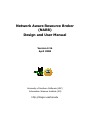
Design and User Manual
Version 2.1b
April 2008
DRAGON
University of Southern California (USC)
Information Sciences Institute (ISI)
http://dragon.east.isi.edu
NARB Design and User Manual v2.1b
April 2008
Table of Contents
1.
2.
3.
4.
5.
6.
7.
Introduction........................................................................................................................................... 1
1.1.
Background ................................................................................................................................. 1
1.2.
NARB Software Design .............................................................................................................. 1
1.2.1. Software Structure .................................................................................................................. 1
1.2.2. Inter-domain LSP Provisioning Process ................................................................................. 2
1.3.
Use Cases .................................................................................................................................... 3
1.3.1. Intra-domain LSP provisioning .............................................................................................. 3
1.3.2. Inter-domain LSP provisioning .............................................................................................. 3
1.3.3. Inter-domain LSP provisioning with ULP.............................................................................. 5
1.3.4. Inter-domain LSP provisioning with CLP .............................................................................. 5
Installation Guide.................................................................................................................................. 6
2.1.
Pre-installation............................................................................................................................. 6
2.1.1. Examining Hardware and Operating System Configurations................................................. 6
2.1.2. Installing VLSR Software....................................................................................................... 6
2.1.3. Downloading the NARB Software Package ........................................................................... 6
2.2.
Compilation and Installation ....................................................................................................... 6
Configuration Guide ............................................................................................................................. 6
3.1.
Preparing Control Plane Network................................................................................................ 7
3.2.
Customizing Configuration File .................................................................................................. 7
3.2.1. Configuration File Structure ................................................................................................... 7
3.2.2. Minimum Configuration: The Single-domain Example ......................................................... 9
Setting Up a Multi-Domain Environment............................................................................................. 9
4.1.
Configuring Inter-domain Control Channels..............................................................................10
4.2.
Summarizing Domain Topology ................................................................................................10
4.3.
Identifying Inter-domain TE Links.............................................................................................12
4.4.
Running Peering NARBs ...........................................................................................................13
4.5.
Provisioning LSP across the Domains........................................................................................13
Command Line Interface (CLI) Reference ..........................................................................................14
5.1.
Commands in the View mode ....................................................................................................14
5.2.
Commands in the Configuration mode.......................................................................................14
5.3.
Editing Abstract TE Link ...........................................................................................................16
5.4.
Editing Static ERO .....................................................................................................................16
5.5.
Preserving CLI Commands in narb.conf ....................................................................................17
Application Programming Interface (API) Reference..........................................................................18
6.1.
API Message Format ..................................................................................................................18
6.2.
LSP Query Messages..................................................................................................................19
6.2.1. Source Client LSP Query Request.........................................................................................19
6.2.2. NARB-NARB Recursive LSP Query Request ......................................................................19
6.2.3. LSP Query Reply with ERO..................................................................................................20
6.2.4. LSP Query Reply with ERO and Confirmation ID................................................................20
6.2.5. LSP Query Reply with ERROR ............................................................................................20
6.2.6. Source/Recursive LSP Reservation Notification ...................................................................20
6.2.7. Source/Recursive LSP Release Notification..........................................................................21
6.2.8. LSP Release Confirmation ....................................................................................................21
6.3.
Optional TLVs............................................................................................................................21
6.3.1. LSP Broker ID TLV ..............................................................................................................21
6.3.2. VLAN Tag Mask TLV ..........................................................................................................21
6.3.3. Suggested VLAN Tag TLV...................................................................................................21
6.3.4. Hop Back Interface TLV .......................................................................................................22
6.3.5. Subnet ERO TLV ..................................................................................................................22
6.3.6. Subnet DTL TLV...................................................................................................................22
6.3.7. Local-ID TLV........................................................................................................................22
Diagnostics and Troubleshooting.........................................................................................................23
7.1.
NARB_Test Client .....................................................................................................................23
ii
NARB Design and User Manual v2.1b
April 2008
8.
9.
Log File ......................................................................................................................................24
7.2.
Conclusion ...........................................................................................................................................24
DRAGON Project ................................................................................................................................25
iii
NARB Design and User Manual v2.1b
April 2008
1. Introduction
Network Aware Resource Broker (NARB) is a key control plane component in the Dynamic Resource
Allocation via GMPLS Optical Networks (DRAGON). This document includes an overview of the NARB
design and a NARB User Manual. Two networking use cases will be described to illustrate the general
NARB usage.
1.1. Background
NARB is an agent which represents an Autonomous or Administrative Domain (AD). The NARB serves as
path computation engine from which end-systems or other devices can query to find out about availability
of traffic engineered paths between specified source and destination pairs. In this document we separate
NARB and Resource Computation Element (RCE) functionalities and let NARB perform the higher-level
functions such as domain level topology abstraction, inter-domain path computation, inter-domain routing
and end-to-end Label Switched Path (LSP) management. RCE will provide NARB with the raw resource
database and path computation services. NARBs peer across domains and exchange topology information
to enable inter-domain path computation and end-to-end LSP provisioning. This inter-domain topology
exchange can be based on the actual topology as discovered by interacting with RCE which listens to the
local Open Shortest Path First (OSPF) protocol, or optionally based on an "abstracted" view of the domain
topology (generated by configuration file or automatic synthesis of the raw RCE resource database). More
background information can be found in the “NARB and RCE Architecture” document.
1.2. NARB Software Design
NARB is designed as a standalone software that provides services to multiple clients simultaneously.
Every NARB client connects to a common server port and maintains a continuous TCP connection during
its entire lifespan. NARB creates an internal server session for each client. The NARB Application
Programming Interface (API) is defined for the NARB server to communicate with its client. NARB also
maintains TCP connections to RCE, OSPF daemons and peer NARBs, These NARB-RCE, NARB-OSPFd
and NARB-NARB communication channels are shared by all the NARB server sessions. The remaining
section provides an overview of the NARB software structure and the basic LSP provisioning process.
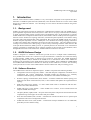
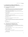
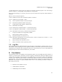
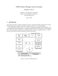
1.2.1. Software Structure
The NARB software structure is depicted in Figure 1. NARB is composed of the following modules:
•
Configuration File Processing (CFP) module – reads and interprets configuration commands from a
configuration file. Typical configuration commands include the description of a manually
summarized domain topology and methods to communicate with OSPFd and NARB peers.
•
Domain Topology Summarization (DTS) module – translates summarized domain topology into
OSPF-TE Link States Advertisements (LSAs). It also maintains and updates the originated domain
topology.
•
OSPF API Client (OAC) module – is a GNU Zebra OSPF client to communicate with the interdomain GNU Zebra OSPF daemon.
•
NARB API Server (NAS) module – creates NARB server sessions, services NARB clients and
interprets NARB API messages.
•
LSP Query Broker (LQB) module – interprets client LSP queries and performs the inter-domain LSP
computation logic with support of local RCE and peer NARBs.
•
RCE API Client Module (RAC) module – communicates with the local RCE server to perform path
computation and resource management functions.
•
NARB API Client Server (NAS) module – communicates with peer NARB servers via NARB API,
particularly for inter-domain routing.
1
NARB Design and User Manual v2.1b
April 2008
•
Command Line Interface (CLI) module – accepts users input via virtual terminals and translates the
CLI commands into internal operations.
•
LSP Schedule Management (ASM) module – maintains a local LSP scheduling table and tracks the
LSP schedule.
•
Authentication, Authorization and Accounting (AAA) module – performs AAA policy related
functionality.
abstract
domain
topology
Figure 1: Network Aware Resource Broker (NARB) software structure.
1.2.2. Inter-domain LSP Provisioning Process
In this subsection, we describe a complete inter-domain end-to-end LSP provisioning process in the context
of the NARB/RCE architecture. We focus on the GMPLS traffic engineering side without considering the
AAA and scheduling issues. We describe the process in the following three control sequences.
1.2.2.1. Request preprocess sequence
An end-to-end service may request a single LSP or a topology consisting of multiple LSPs. In the latter
case, the topology request is decomposed into separate LSP requests by ASTB. Each LSP request is
translated into an LSP query request to NARB. Only if NARB returns the explicit routing path for every
LSP, will the actual resource allocation (signaling) process be kicked off.
The format of an LSP request is shown below:
LSP-REQ = {Type, Source IP/Port, Destination IP/Port, LSP Bandwidth, EncType, SwType,
tWinOpen, tWinClose, tDuration, User ID, <User Profile>, <SLA Parameters>}
There are four types of LSP requests. They are:
A. LSP with both source and destination in the current domain;
B. LSP with only source in the current domain;
C. LSP with only destination in the current domain; and
D. LSP with both source and destination in foreign domains.
The requests of types A and B are sent to the local NARB, which proceeds to the LSP query sequence. The
requests of types C and D are sent to corresponding foreign NARBs through NARB-to-NARB
communication. A home identifier tag is added to those requests. Upon receiving an LSP request, a foreign
2
NARB Design and User Manual v2.1b
April 2008
NARB will proceed to the LSP query sequence. When the query is done, the foreign NARB will return the
results back to the home NARB.
1.2.2.2. LSP query sequence
Upon receiving an LSP request, the NARB directs it to the LSP provisioning module. The LSP
provisioning module firstly translates time schedule attributes, user profile and SLA parameters into
routing constraints understandable for RCE. Then a path request with TE constraints and other translated
constraints is passed to the RCE for path computation. RCE will compute a path for the LSP request based
on known local and global resource information. For an LSP across multiple domains, a recursive process
may be performed via NARB-NARB communication to obtain end-to-end results using one of the interdomain path computation schemes described in section 1.3.
When a desired LSP path is obtained, the LSP provisioning module sends resource-holding requests to the
resource management module in NARB to request holding all the RCE resources allocated to that LSP. The
purpose of the holding procedure is to avoid inconsistent resource allocation between simultaneous LSP
request sessions. To hold the requested resources, states of corresponding resource data in the RCE TEDB
(i.e., time slots for resources) are changed into held, which avoids contention from other provisioning
sessions. If a resource is in a foreign domain, the resource management module should forward the request
to its foreign peer, asking for holding that resource.
Only after the resource management module acknowledges that all the requested resources are held, can the
LSP provisioning module acknowledge the requestor with a success. Otherwise, a failure is returned and all
held resources are released.
1.2.2.3. LSP setup sequence
After all the LSP requests are responded with success, the LSP setup sequence is executed. In this sequence
the states of those held resources will be changed into reserved. The LSP provisioning sequence involves
the interaction with Client System Agents (CSA, see section 2) and the signaling process. In this document,
we skip this part of description.
1.3. Use Cases
We illustrate the NARB functionality by four networking use cases as described below.
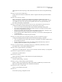
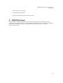
1.3.1. Intra-domain LSP provisioning
Figure 2 illustrates a base NARB use case in a single-domain network. In this single autonomous domain,
NARB receives and verifies users LSP requests and converts them into path computation requests to RCE,
which has obtained the whole local topology by listening to a local OSPF daemon (OSPFd). The path
computation result from RCE can be used for NARB to directly create an Explicit Route Object (ERO) to
the user. Upon a failed path computation, an error code is returned. Note that a user can be an application
running on the end systems, an ASTB, a third-party LSP agent, or a signaling component that is in need of
routing path during a signaling process.
In a domain that contains a subnet, intra-domain LSP path computation and provisioning will need to create
bridges to the subnet level and Subnet ERO or Designated Transit List (DTL) may be used along with the
main ERO. Refer to Appendix A of the NARB and RCE Architecture Document for further information.
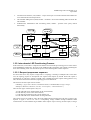
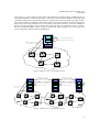
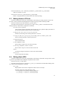
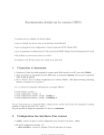
1.3.2. Inter-domain LSP provisioning
Figure 3 illustrates a more sophisticated NARB use case with three domains. Each domain has a NARB
connected to an additional instance of inter-domain OSPFd. These inter-domain OSPFd’s are isolated with
those intra-domain OSPFd’s. They interact with one another in a higher-level to create a global,
summarized topology that is above the local, physical topologies of individual domains. In this interdomain case, NARB abstracts and originates its represented local domain topology to an inter-domain
OSPFd, which floods the abstract topology to other domains to put together a global, summarized, higher3
NARB Design and User Manual v2.1b
April 2008
level topology. Upon an end-to-end LSP request with destination in another domain, NARB performs an
initial path computation with RCE that listens to both intra- and inter-domain OSPFd’s. The initial path
computation should return a hybrid path with precise, physical hops in the local domain and rough, abstract
hops in other domains. NARB then communicates with the next-domain NARB to complement the initial
path with precise routing information in a next domain. Doing that recursively, the source NARB can
obtain a full strict-hop ERO for the requested end-to-end LSP. The path computation scheme is called a
Recursive Per-Domain (RPD) scheme. Using the all-strict-hop ERO, signaling can set up a path from
source to destination without contacting NARB again.
NARB
2.Request for Path Computation
3.PAth Computation Result
RCE
1.ESA requests for LSP
from LSR1 to LSR5
intra-domain
ospfd
4.Return ERO or ErrorCode
LSR2
LSR1
LSR3
LSR4
LSR5
Figure 2: NARB use case in a single-domain network.
4.Recursive LSP request
inter-domain
ospfd.1
7.Recursive LSP request
11.Return partial ERO or ErrorCode
NARB
inter-domain
ospfd.2
1.ESA requests for LSP
from LSR1.1 to LSR3.2
inter-domain
ospfd.3
NARB
NARB
8
5.Request for Path Computation
2.Request for Path Computation
RCE
10.Return partial ERO or ErrorCode
RCE
3.Path Computation Result
intra-domain
ospfd.1
6.Path Computation Result
RCE
9
intra-domain
ospfd.3
intra-domain
ospfd.2
12.Return full ERO or ErrorCode
LSR1.1
LSR1.2
LSR1.3
LSR2.1
LSR2.2
LSR3.1
Domain 2
LSR3.2
Domain 1
LSR1.4
LSR1.5
LSR2.3
LSR2.4
LSR3.3
Domain 3
Figure 3: NARB use case in a multi-domain network.
4
NARB Design and User Manual v2.1b
April 2008
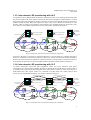
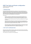
1.3.3. Inter-domain LSP provisioning with ULP
As explained in the “NARB and RCE Architecture” document (Section 4.3.3), obtaining all-strict-hop ERO
may not be feasible when other domains want to hide their private topologies. NARB supports a Forward
Per-Domain (FPD) path computation scheme, which does not require strict-hop ERO being passed between
NARBs. Instead an initial ERO will contain strict hops in the source domain and loose-hops in next
domains, which is called an Unconfirmed Loose-hop Path (ULP). Signaling daemon at each border router
will contact its local NARB to expand the loose hops. This scheme is illustrated in Figure 4.
NARB
RCE
1.ESA request for LSP
10.Request for
Path Computation
NARB
NARB
7.Request for Path Computation
2. Request for Path Computation
RCE
3. Path Computation Result
RCE
8. Path Computation Result
11. Path Computation
Result
4. Return ULP ERO
6. Resolve loose hops in ULP ERO
LSR2
LSR1
5. Start signaling with ULP
9. Resolve loose hops in ULP ERO
LSR2.
1
LSR3
LSR3.
1
LSR2.
2
Domain 2
LSR3.
2
Domain 1
LSR2.
3
LSR4
LSR5
LSR3.
3
LSR2.
4
Domain 3
Figure 4: Illustration of the ULP-based inter-domain path computation.
As shown in the figure, a ULP ERO is computed at Domain 1. Using the initial ULP, signaling proceeds to
Router 2.1 in Domain 2 and then resolves the loose hops in the ULP by contacting the Domain-2 NARB to
obtain a new ULP which allows signaling to continue to Domain 3. The procedure is performed recursively
until reaching the destination. No strict-hop ERO segment is passed beyond the domain it belongs to.
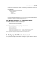
1.3.4. Inter-domain LSP provisioning with CLP
To obtain deterministic end-to-end path computation results and avoid contention, path Query
Confirmation (Q-Conf) and Query Holding (Q-Hold) are introduced into NARB design. The basic idea is
to guarantee that a physical (all-strict-hop) path exists and hold the resources in need when querying a
multi-domain path. This scheme results in a Confirmed Loose-Hop Path (CLP) which observes both
domain privacy and path determinability. The scheme is illustrated in Figure 5.
11. Return Q-Conf ID or ErrorCode
10. Return Q-Conf ID or ErrorCode
4. Recursive LSP request
with Q-Conf ID
NARB
7. Recursive LSP request
With Q-Conf ID
RCE
3. Path Computation Result
12. Return CLP ERO with Q-Conf ID
(or ErrorCode)
LSR2
LSR1
13. Start signaling with Q-Conf ID
LSR3
8.Request for
Path Computation
5.Request for Path Computation
2. Request for Path Computation
1.ESA request for LSP
with Q-Conf ID
NARB
NARB
RCE
14. Resolve loose hops in CLP ERO with Q-Conf ID
LSR2.
1
Domain 2
RCE
6. Path Computation Result
9. Path Computation
Result
15. Resolve loose hops in CLP ERO with Q-Conf ID
LSR2.
2
LSR3.
1
LSR3.
2
Domain 1
LSR4
LSR5
LSR2.
3
LSR2.
4
LSR3.
3
Domain 3
Figure 5: Illustration of the CLP-based inter-domain path computation.
5
NARB Design and User Manual v2.1b
April 2008
As shown in the figure, the collaborative NARBs first need to perform a recursive path computation via
NARB-NARB communication just as the RPD scheme does. The difference is that instead of the strict-hop
ERO, only a confirmation ID is passed back from downstream domains to confirm that a strict-hop path
exist. Signaling from Domain 1 uses the CLP to reach Router 2.1 in Domain 2. Then the confirmation ID is
presented to Domain-2 NARB, which returns a new CLP that has been generated by the initial path
computation. Meanwhile the related resources being held will now become reserved. This procedure is
repeated recursively until reaching the destination.
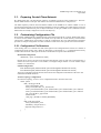
2. Installation Guide
2.1. Pre-installation
2.1.1. Examining Hardware and Operating System Configurations
The NARB software runs on a Linux or FreeBSD operating system. Hardware requirements include
Pentium III CPU or above, at least 512 MB RAM and at least 1 GB free hard disk space. Linux server or
workstation with kernel version 2.4 or above (e.g., RedHat Linux v9) and FreeBSD 5.1-RELEASE or
above are recommended. Compiling the software requires GNU GCC/G++ 3.2 or above.
2.1.2. Installing VLSR Software
The VLSR software can be downloaded from:
http://dragon.east.isi.edu ====> VLSR ====> dragon-sw-snapshot.xxxx.tar.gz
A minimum installation of the Zebra OSPFd module is required. Refer to the DRAGON Virtual Label
Switching Router Implementation Guide for general DRAGON Software installation and configuration
instructions.
2.1.3. Downloading the NARB Software Package
The NARB software package is available at:
http://dragon.east.isi.edu ====> NARB ====> narb-sw-snapshot.xxxx.tar.gz
2.2. Compilation and Installation
GNU GCC 3.2 or above is required for compilation of the software. Extract the package to a working
directory, e.g. /usr/local/narb. To compile and install,
#cd narb-sw
#./do_build.sh
#./do_install.sh
Read the INSTALL document under the narb directory for more installation information. To run the
software, narb.conf and schema_combo.rsd must exist under the configuration directory, which is
/usr/local/dragon/etc by default. Sample narb.conf and schema_combo.rsd files are installed under the
configuration directory. More details on narb.conf are available in the next section. schema_combo.rsd can
be literally copied from schema_combo.rsd.sample for most users to begin with. Advanced users can refer
to the DRAGON RCE User Manual for more information. To run both NARB and RCE, use the following
command
#/usr/local/dragon/bin/run_narb.sh
3. Configuration Guide
In a real network, the following configuration must be done before we actually run the NARB software.
6
NARB Design and User Manual v2.1b
April 2008
3.1. Preparing Control Plane Network
By default, both intra- and inter-domain instances of OSPFd are hosted on the NARB server. The interdomain OSPFd listens to API port 2607 and the intra-domain OSPFd listens to API port 2617.
The OSPF adjacency between the intra-domain OSPFd on the NARB server and the OSPFd on one of
operational network nodes in the local domain should be created. In addition, the OSPF adjacency between
the inter-domain OSPFd and its peers in adjacent domains (on the peer NARB servers) should be created.
GRE tunnels are usually configured to service such adjacency.
3.2. Customizing Configuration File
When started, NARB loads the configuration file in the path specified by the -f option. Without this option,
it searches for the default configuration file named narb.conf under the current directory and then under
/usr/local/etc. NARB aborts when failing to load the configuration file. The narb/narb/narb.conf.sample
provides an example configuration. We must customize a narb.conf in each specific network environment.
3.2.1. Configuration File Structure
Lines starting with ! are comment lines and will be ignored. The configuration file consists of a number of
configuration blocks starting with a block id, followed by a block body in {}. A configuration block may
contain sub-level blocks. The top-level blocks are divided into four parts as described below.
Domain ID Configuration
domain-id { ip IP | id NUM | asn ASN}
Domain ID is used to associate each advertised inter-domain router or link with a unique domain. A
domain ID can be expressed as an IP address, an unsigned integer number or an AS number (single
number or in A.B format).
OSPFd Configuration
inter-domain-ospfd {address HOST port NUM originate-interface IP area IP}
intra-domain-ospfd {address HOST port NUM originate-interface IP area IP}
These two configuration blocks describe the location and configuration information of the inter- and
intrRA-domain OSPF daemons.
Abstract Topology Configuration
In an abstract topology, we use a router configuration block to describe each router.
router {id IP
link { id IP type NUM
local_if IP remote_if IP
max_bw FLOAT max_rsv_bw FLOAT
unrsv_bw0 FLOAT unrsv_bw1 FLOAT unrsv_bw2 FLOAT unrsv_bw3 FLOAT
unrsv_bw4 FLOAT unrsv_bw5 FLOAT unrsv_bw6 FLOAT unrsv_bw7 FLOAT
enc_type NUM sw_type NUM
metric NUM
vlan_tags {VLANs or VLAN_RANGEs}
}
link {id IP type NUM
local_if IP remote_if IP
Mandatory TE parameters…
Optional TE parameters …
}
}
7
NARB Design and User Manual v2.1b
April 2008
A router block has a router id and one or more sub-level link blocks. Each link block represents a TE
link originating from this router. The router id will be its advertising router. Four parameters, link id,
link type, and local and remote interface addresses, are mandatory. In path computation, router id, link
id and local and remote interface addresses are used together to generate the network graph.
Mandatory link TE parameters include metric, max_bw, max_rsv_bw, unrsv_bw0…unrsv_bw7,
enc_type, and sw_type. When the parameter metric does not show up, NARB sets a default metric
value 1. Optional TE parameters are needed for constraining the path computation in technologyspecific layers. For instance, vlan_tags{VLANs or VLAN_RANGEs} is required for L2SC layer links.
Topology Abstraction with Auto-Link Configuration
Auto-link is a feature that allows NARB to automatically generate abstract TE links by probing
corresponding local paths based on the RCE intra-domain TEDB. To generate auto-links a router will
be defined as either a border router or an edge/stub router. NARB will create abstract links between
every pair of border routers and between every border and edge routers where a local path exists.
One or more te_profile configuration blocks must be present before being referenced by the router
configuration blocks. An example is:
te-profile { id 1 sw_type 51 enc_type 2 bandwidth 1000.0 }
A border router configuration block contains an auto-link statement, which refers to the ID number of
the te_profile that is used to constrain the local path computation by RCE. This single line of ‘autolink’ statement can save a number of manual configured link blocks. One or more regular link
statements are still needed to configure those inter-domain TE links.
router {id 10.100.10.233
auto-link border te-profile {1}
link {id 140.173.10.232 type 1
local_if 10.100.10.38 remote_if 10.100.10.37
Mandatory TE parameters…
Optional TE parameters …
}
}
An edge/stub router configuration block only contains an ‘auto-link’ statement.
router {id 10.100.10.235
auto-link edge te-profile {1}
}
Topology Abstraction with Auto-Topo Configuration
Auto-link is a feature that allows NARB to generate abstract TE links by simply duplicating the intradomain physical topology from RCE TEDB. The statement is as follows.
auto-topo-rce {phy any-domain l2sc}
where phy means physical topology, any-domain means taking links from any domains which are
identified by the DRAGON-specific domain-ID TE Link TLV, and l2sc means taking the L2SC layer
links. One may also add other layers such as lsc, tdm, psc1…pcs4.
Inter-Domain TE Link Configuration
inter-domain-te-link {id IP narb-peer HOST port NUM}
This configuration block defines the inter-domain TE links. We can have one or more inter-domain-telink blocks. The id here must be to the remote_if under one of the link blocks in the above abstract
topology, which corresponds to the remote end TE address attached to a neighboring domain. narbpeer and port describe the location information of a peering NARB server in a neighboring domain,
where narb-peer address is usually the remote end of the GRE tunnel serving this inter-domain TE link.
8
NARB Design and User Manual v2.1b
April 2008
Note that when using the auto-link or auto-topo configurations, we still need the inter-domain-te-link
statements because inter-domain TE links cannot be automatically identified.
CLI Configuration
cli {host NAME password PASSPHRASE
execute-commands {
`configure`
`command line 2`
`……`
}
}
host specifies the NARB’s identifying name that a user sees when logging into the NARB CLI.
password provides the authentication for user to access the CLI. The execute-commands statement can
contain arbitrary NARB CLI commands, each line quoted with ‘, `or “.
3.2.2. Minimum Configuration: The Single-domain Example
The minimum configuration is as simple as having just one line.
! The DRAGON network narb configuration file
cli {host dragon-narb password dragon}
!
When NARB starts running, the following log messages will be printed out.
#####################
DRAGON NARB Started...
#####################
NARB_OUTPUT @[2006/04/28 16:56:14] : Running without connection to OSPFd......
NARB_OUTPUT @[2006/04/28 16:56:14] : No abstract topology generated......
A more sophisticated configuration example will be described in the next section.
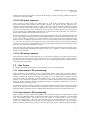
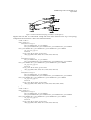
4. Setting Up a Multi-Domain Environment
This section elaborates NARB and related software configuration by providing a full network deployment
context, which is in an example two-domain environment as depicted in Figure 6.
9
NARB Design and User Manual v2.1b
April 2008
Internet
eth0: 65.114.168.156
inter-domain
ospfd.1
NARB
Server
NARB.1
eth0: 206.196.176.229
gre1
GRE 10.0.1.1/30
GRE 10.0.1.2/30
inter-domain
ospfd.2
RCE
intra-domain
ospfd.1
GRE 10.1.1.1/30
GRE 10.1.2.2/30
gre2
Domain 1
10.2.10.0/24
NARB
Server
RCE
TE 10.32/30
NARB.2
gre3
TE 10.73
LSR1.2
TE 10.40/30
TE 10.48/30
41
TE 10.64/30
49
Domain 2
10.2.20.0/24
GRE 10.1.2.1/30
GRE 10.1.1.2/30
LSR1.1
intra-domain
ospfd.2
TE 20.40/30
TE 10.74
LSR2.1
TE 20.32/30
Interdomain
TE links
41
49
LSR2.2
TE 20.48/30
57 TE 10.56/30
TE 12.66
LSR1.3
TE 20.65
LSR2.3
LSR1.4
Figure 6: An example network configuration with NARB in a two-domain environment.
4.1. Configuring Inter-domain Control Channels
With reference to the configuration depicted in Figure 6, the following GRE tunnels are created to provide
inter- and intra-domain OSPF adjacency.
gre1 (10.0.1.0/30): inter-domain OSPF adjacency between the two NARB peers.
gre2 (10.1.1.0/30): intra-domain OSPF adjacency between NARB.1 and Domain 1.
gre3 (10.1.2.0/30): inter-domain OSPF adjacency between NARB.2 and Domain 2.
In Domain-1 narb.conf, the following ospfd related configuration blocks are added. We suppose the interdomain OSPF flooding area is 1 and the two intra-domain OSPF flooding areas are 0. The originateinterface uses the local-end IP address of the GRE tunnel that the OSPF adjacency relies on.
inter-domain-ospfd {address localhost port 2607 originate-interface 10.0.1.1 area 0.0.0.1}
intra-domain-ospfd {address localhost port 2617 originate-interface 10.2.10.1 area 0.0.0.0}
In Domain-2 narb.conf, the following ospfd related configuration blocks are added.
inter-domain-ospfd {address localhost port 2607 originate-interface 10.0.1.2 area 0.0.0.1}
intra-domain-ospfd {address localhost port 2617 originate-interface 10.2.20.2 area 0.0.0.0}
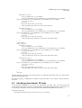
4.2. Summarizing Domain Topology
Suppose Domain 1 is summarized into an abstract topology with three nodes LSR1.2, LSR1.3 and LSR1.4
and Domain 2 into LSR2.1, LSR2.2 and LSR2.3 that is identical to its physical topology. The abstract
topology of Domain 1 will look like in Figure 7.
10
NARB Design and User Manual v2.1b
April 2008
Figure 7: Abstract/summarized topology of Domain 1 (from Figure 6).
Suppose that each link is a bidirectional 10GigE link with certain allowed VLAN tags. The topology
configuration block in Domain-1 narb.conf is defined as follows.
! Node - LSR 1.2
router {id 10.2.1.2
link {id 10.2.1.3 type 1
max_bw 10000.0 max_rsv_bw 10000.0
unrsv_bw0 10000.0 unrsv_bw1 10000.0 unrsv_bw2 10000.0 unrsv_bw3 10000.0
unrsv_bw4 10000.0 unrsv_bw5 10000.0 unrsv_bw6 10000.0 unrsv_bw7 10000.0
enc_type 2 sw_type 51
metric 10
local_if 10.2.10.34 remote_if 10.2.10.41
vlan_tags(3000, 3001, 3010, 3011, 3020, 3021, 4001:10)
}
link {id 10.2.1.3 type 1
max_bw 10000.0 max_rsv_bw 10000.0
unrsv_bw0 10000.0 unrsv_bw1 10000.0 unrsv_bw2 10000.0 unrsv_bw3 10000.0
unrsv_bw4 10000.0 unrsv_bw5 10000.0 unrsv_bw6 10000.0 unrsv_bw7 10000.0
enc_type 2 sw_type 51
metric 10
local_if 10.2.10.50 remote_if 10.2.10.49
vlan_tags(3000, 3001, 3010, 3011, 3020, 3021, 4001:10)
}
link {id 10.2.1.4 type 1
max_bw 10000.0 max_rsv_bw 10000.0
unrsv_bw0 10000.0 unrsv_bw1 10000.0 unrsv_bw2 10000.0 unrsv_bw3 10000.0
unrsv_bw4 10000.0 unrsv_bw5 10000.0 unrsv_bw6 10000.0 unrsv_bw7 10000.0
enc_type 2 sw_type 51
metric 10
local_if 10.2.10.65 remote_if 10.2.10.66
vlan_tags(3000, 3001, 3010, 3011, 3020, 3021, 4001, 4002, 4003)
}
}
! Node - LSR 1.3
router {id 10.2.1.3
link {id 10.2.1.2 type 1
max_bw 10000.0 max_rsv_bw 10000.0
unrsv_bw0 10000.0 unrsv_bw1 10000.0 unrsv_bw2 10000.0 unrsv_bw3 10000.0
unrsv_bw4 10000.0 unrsv_bw5 10000.0 unrsv_bw6 10000.0 unrsv_bw7 10000.0
enc_type 2 sw_type 51
metric 10
local_if 10.2.10.41 remote_if 10.2.10.34
vlan_tags(3000, 3001, 3010, 3011, 3020, 3021, 4001:10)
11
NARB Design and User Manual v2.1b
April 2008
}
link {id 10.2.1.2 type 1
max_bw 10000.0 max_rsv_bw 10000.0
unrsv_bw0 10000.0 unrsv_bw1 10000.0 unrsv_bw2 10000.0 unrsv_bw3 10000.0
unrsv_bw4 10000.0 unrsv_bw5 10000.0 unrsv_bw6 10000.0 unrsv_bw7 10000.0
enc_type 2 sw_type 51
metric 10
local_if 10.2.10.49 remote_if 10.2.10.50
vlan_tags(3000, 3001, 3010, 3011, 3020, 3021, 4001:10)
}
link {id 10.2.1.4 type 1
max_bw 10000.0 max_rsv_bw 10000.0
unrsv_bw0 10000.0 unrsv_bw1 10000.0 unrsv_bw2 10000.0 unrsv_bw3 10000.0
unrsv_bw4 10000.0 unrsv_bw5 10000.0 unrsv_bw6 10000.0 unrsv_bw7 10000.0
enc_type 2 sw_type 51
metric 10
local_if 10.2.10.57 remote_if 10.2.10.58
vlan_tags(3000, 3001, 3010, 3011, 3020, 3021, 4001, 4002, 4003)
}
}
! Node - LSR 1.4
router {id 10.2.1.4
link {id 10.2.1.2 type 1
max_bw 10000.0 max_rsv_bw 10000.0
unrsv_bw0 10000.0 unrsv_bw1 10000.0 unrsv_bw2 10000.0 unrsv_bw3 10000.0
unrsv_bw4 10000.0 unrsv_bw5 10000.0 unrsv_bw6 10000.0 unrsv_bw7 10000.0
enc_type 2 sw_type 51
metric 10
local_if 10.2.10.58 remote_if 10.2.10.57
vlan_tags(3000, 3001, 3010, 3011, 3020, 3021, 4001, 4002, 4003)
}
link {id 10.2.1.3 type 1
max_bw 10000.0 max_rsv_bw 10000.0
unrsv_bw0 10000.0 unrsv_bw1 10000.0 unrsv_bw2 10000.0 unrsv_bw3 10000.0
unrsv_bw4 10000.0 unrsv_bw5 10000.0 unrsv_bw6 10000.0 unrsv_bw7 10000.0
enc_type 2 sw_type 51
metric 10
local_if 10.2.10.66 remote_if 10.2.10.65
vlan_tags(3000, 3001, 3010, 3011, 3020, 3021, 4001, 4002, 4003)
}
}
! The end
Note that the tags in vlan_tags can be discrete values, e.g., 3000, 4001, plus value ranges, e.g., 4001:10 that
represents 4001 through 4010.
We skip the topology configuration in Domain-2 narb.conf, which is very similar to that in Domain-1
narb.conf.
4.3. Identifying Inter-domain TE Links
In this network configuration, we can see two inter-domain TE links. They are 10.2.10.72/30 and
10.2.20.64/30 respectively. We need to configure both in the NARB configuration file. Note that the ‘id’
and ‘narb-peer’ IP addresses are the remote-end TE link and GRE tunnel addresses respectively.
In Domain-1 narb.conf:
inter-domain-te-link {id 10.2.10.74 narb-peer 10.0.1.2 port 2609}
12
NARB Design and User Manual v2.1b
April 2008
inter-domain-te-link {id 10.2.20.65 narb-peer 10.0.1.2 port 2609}
In Domain-2 narb.conf:
inter-domain-te-link {id 10.2.10.73 narb-peer 10.0.1.1 port 2609}
inter-domain-te-link {id 10.2.20.66 narb-peer 10.0.1.1 port 2609}
4.4. Running Peering NARBs
NARB and the related software have to be started in the following sequence.
1.
2.
3.
Start intra- and inter-domain OSPFd in every domain.
Start RCE in every domain.
Start NARB in every domain.
Steps 2 and 3 can be started in a batch by using the /usr/local/dragon/sbin/run_narb.sh script.
With inter-domain OSPFd configured, NARB will check the status of the OSPF adjacency on the originateinterface. NARB will originate a topology only if the OSPF adjacency on this originate-interface is in Full
state. Otherwise, NARB will enter a loop waiting for the OSPF adjacency being formed and the user should
see the following screen.
#####################
DRAGON NARB Started...
#####################
NARB_OUTPUT @[2007/08/24 15:24:33] : Initiating NARB Zebra OSPF API client......
NARB@[2007/08/24 15:24:33] : RegisterOpqaueType [10,1]
NARB@[2007/08/24 15:24:33] : Inter-domain OSPF interface 0x216020a is not ready
... wait 10 seconds...
NARB@[2007/08/24 15:24:43] : Inter-domain OSPF interface 0x216020a is not ready
... wait 10 seconds...
NARB@[2007/08/24 15:24:53] : Inter-domain OSPF interface 0x216020a is not ready
... wait 10 seconds...
4.5. Provisioning LSP across the Domains
Suppose we want to provision a 1 GigE LSP (Ethernet VLAN) from LSR 1.2 to LSR 2.2. We can to issue
following commands through the CLI of the DRAGON client system agent (CSA) on the LSR 1.2.
edit lsp test-lsp
set uni client ingress implicit egress implicit
set source ip 10.2.1.2 lsp-id 1234 destination ip-address 10.2.2.2 tunnel-id 4321
set bandwidth gige swcap l2sc encoding ethernet gpid ethernet
set vtag 3010
exit
commit lsp test-lsp
The DRAGON CSA will act as a NARB API client and send an LSP query request to NARB.1, which will
in turn work with RCE and NARB.2 to compute a full explicit route for this request. Then RSVPD can use
the obtained ERO to signal up an end-to-end GigE Ethernet VLAN (using tag 3010) from LSR1.2 to
LSR2.2 crossing the two domains. Refer to the DRAGON Software Release 1.0 document for more
information on usage of DRAGON CSA.
13
NARB Design and User Manual v2.1b
April 2008
5. Command Line Interface (CLI) Reference
NARB CLI server listens to port 2626 for telnet connections. After logged in to NARB CLI via telnet, one
is under the View mode with “narb:cli>” as the shell prompt.
5.1. Commands in the View mode
narb:cli> show module
Displays addresses, ports and status of the inter- and intra-domain instances of OSPFd, the RCE,
and all the peering NARBs in adjacent domains. Status of OSPFd is two-fold: (a) whether the
OSPFd is online; (b) whether the API client connection to OSPFd is alive. Status of a peering
NARB also shows a list of next-domain interface addresses associated with the NARB.
narb:cli> show ospfd (interdomain | intradomain)
Displays host address, local and remote ports, LSA origination interface and area ID of the interor intra-domain OSPFd.
narb:cli> show topology
Displays all the router-id and te-link LSAs originated from this NARB as well as the IDs of interdomain TE links.
narb:cli> show link local_if_addr IP remote_if_addr IP
Display details of individual TE link, the local_if_addr and remote_if_addr can be obtained from
the ‘show topology’ output.
narb:cli> show lsp
Displays parameters and status of all the LSPs managed by this NARB.
narb:cli> show static_ero <SRC_DEST>
Displays a list of static/manually configured EROs, each with 'enabled' or 'disabled' status. When
the optional source-destination address pair is present, display details of the matched static ERO.
narb:cli> exit
Logs off the NARB CLI.
narb:cli> configure
Enters the Configuration mode. The shell prompt changes into “narb:cli#”.
5.2. Commands in the Configuration mode
narb:cli# show{topology|link|static_ero|rce|routing-mode|working-mode}
In addition to showing topology, link and static_ero that are the same as in the View mode, one
can also see the RCE state, NARB routing mode and NARB working mode. Each of these will be
further explained with other commands.
narb:cli# set rce HOST port PORT
Configure RCE daemon parameters. (“show rce” to see whether the configured RCE is online.)
narb:cli# delete rce HOST port PORT
Delete a configured RCE.
narb:cli# set narb-peer HOST port NUM via ADDR
Reconfigure parameters for a peering NARB. A new interface address ADDR associated with this
NARB may be added.
narb:cli# set topology FILE
14
NARB Design and User Manual v2.1b
April 2008
(Re)originate the abstract topology of this domain described in the FILE into the global flooding
area.
narb:cli# set refresh-interval SECONDS
Set the value interval between refreshments, which re-originate LSAs that represent the abstract
topology.
narb:cli# set forced-merge {on|off}
When “forced-merge” is turned on in the RPD path computation, NARB merges what ever
returned from the next domain into the initially computed ERO. When “forced-merge” is turned
off, NARB must check if the returned strict-hop ERO matches the exact path indicated by the
loose hops in the initially computed ERO.
narb:cli# set routing-mode (all-loose-allowed | all-strict-only | mixed-allowed | mixed-preferred)
Configure the routing mode that determines how routing request is processed.
•
all-strict-only mode: All-strict-hop ERO must be returned, the default routing mode.
•
mixed-allowed mode: Return as many as possible strict hops. Loose hops are allowed when
they cannot be expanded into strict hops.
•
mixed-preferred mode: Only the hops in the current domain are strict hops. The hops in next
domains must be loose hop. In other words, a ULP must be returned.
•
mixed-confirmed mode: NARB works in Q-Conf mode. A CLP ERO is returned together will
a confirmation ID.
•
all-loose-allowed mode: All hops may be loose hops.
narb:cli# set working-mode (static-interdomain-topology | dynamic-interdomain-topology)
Configure the working mode that determines how inter-domain topology is updated.
•
•
static-interdomain-topology mode: Static topology is exchanged. No topology updates (due to
provisioning) are sent out.
dynamic-interdomain-topology mode: The default working mode that always sends out
topology updates when LSPs are set up or torn down.
narb:cli# set ospfd (interdomain | intradomain) HOST LCL_PORT RMT_PORT ORI_IF AREA
Reconfigure inter- or intra-domain OSPFd parameters.
narb:cli# connect ospfd (interdomain | intradomain)
(Re)Connect to an OSPF daemon. Upon success of connection, domain summary is (re)originated.
narb:cli# delete ospfd (interdomain | intradomain)
Disconnect to an OSPF daemon.
narb:cli# delete topology
Remove the abstract topology of this domain from the global flooding area.
narb:cli# undelete topology
Undo the ‘delete topology’ command.
narb:cli# set static_ero SRC-DEST {enabled | disabled}
Enable or disable a preconfigured static ERO. When enabled, NARB always returns this static
ERO to the request that match the source destination IP addresses.
narb:cli# delete static_ero SRC-DEST
Remove a preconfigured static ERO.
narb:cli# exit
Exit from the topology configuration mode.
15
NARB Design and User Manual v2.1b
April 2008
narb:cli# add link adv_router ADDR link_id ADDR lcl_if_addr ADDR rmt_if_addr ADDR
Add a new TE link to a router.
narb:cli# delete link local_if_addr ADDR rmt_if_addr ADDR
Delete a configured abstract TE link from the inter-domain topology.
5.3. Editing Abstract TE Link
Under the Configuration mode, the command below starts editing an existing abstract TE link. This
provides a means to manually update/adjust/fix the abstract topology without restarting NARB.
narb:cli# edit link local_if_addr ADDR rmt_if_addr ADDR
The shell prompt changes into “narb:cli#(local_if_addr-remode_if_addr)” Commands in the LinkEditing mode are a subset of the Configuration commands.
show link (original | updated)
“show original” displays the details of the original TE. “show updated” displays the details of
the TE link with all the changes under the current editing.
set (link_id | adv_router | metric | lcl_if | rmt_if) VALUE
Set link ID, advertising router and TE parameters to VALUE.
set swcap (lsc | tdm | psc1 | psc2 | psc3 | psc4) encoding (ethernet | lambda | packet | sdh)
Set the switching capability related TE parameters.
set bandwidth FLOAT
Set the link bandwidth.
set vlan {add|delete} VTAG
Add or delete a single VLAN from the current link.
set vlan-range {add|delete} VTAG1 to VTAG2
Add or delete a range of VLANs from the current link.
commit
Commit the changes and advertise it to the inter-domain OSPFd.
cancel or exit
Cancel and quit the link editing.
5.4. Editing Static ERO
Under the Configuration mode, the command below starts editing a static ERO. This provides a means
to generate a special ERO that NARB path computation fails to obtain.
narb:cli# edit static_ero SRC-DEST
The shell prompt changes into “narb:cli#(src_ip-dest_ip)” Commands in the StaticERO-Editing mode
are a subset of the Configuration commands.
show config
Display details of the current configuration. Below shows an example.
narb:cli#(10.100.70.232-10.100.70.223)show config
## showing 4 ERO (status 'enabled') subobjects (cursor=-1) >>
>>1 : (strict-hop) -- 10.100.70.42 -- Unum ifID=0x40064
>>2 : (strict-hop) -- 10.100.70.41 -- Unum ifID=0x1065ff
16
NARB Design and User Manual v2.1b
April 2008
>>3 : (strict-hop) -- 10.100.70.38 -- IPv4
>>4 : (strict-hop) -- 10.100.70.37 -- IPv4
enable | disable
Enable of disable this static ERO.
clear
Clear all subobjects in the ERO.
delete subobject N
Delete the N-th subobject in the ERO.
insert {before|after} N
The next subobject will be set before and after the N-th subobject in the current ERO. Using
the above example, “insert before 2” and then “show configure,” one should see
narb:cli#(10.100.70.232-10.100.70.223)show config
## showing 4 ERO (status 'enabled') subobjects (cursor=1) >>
… where the ‘cursor’ becomes 1. “insert after 2”, the cursor will become 2.
append
New subobject will be appended to the current ERO. (‘cursor’ now will be -1.)
set subobject {strict|loose} ipv4 IP
Add a new subobject of IPv4 type.
set subobject {strict|loose} unnumbered interface-ipv4 IP id ID
Add a new subobject of Unnumbered Interface ID type.
set subobject {strict|loose} vlan-te interface-ipv4 IP vtag VTAG
Add a new subobject of Unnumbered Interface ID type but carrying the special VLAN-TE
interface ID.
set subobject {strict|loose} subnet {source|destination} interface-ipv4 IP id SUBNETID
Add a new subobject of Unnumbered Interface ID type but carrying the special
Source/Destination Subnet interface ID.
set subobject {strict|loose} local-id {port|group|tagged-group|subnet-interface} loopback-ipv4 IP
id LCL_ID
Add a new subobject of Unnumbered Interface ID type which is a local ID.
set dtl-hop node-name NAME_STR link-id ID_NUM
Add a subnet DTL hop. The first command creates the DTL and subsequent commands
append new hops.
exit
Quit the Static-ERO-Editing mode. The current configuration will kept in NARB until being
explicitly deleted. The default status will be ‘disabled.’
5.5. Preserving CLI Commands in narb.conf
As explained in 3.2.1, arbitrary CLI commands can be preconfigured with the cli { executecommands{} } statement in narb.conf. This provides a means to preserve CLI commands and let NARB
automatically execute those preconfigured commands every time it is restarted.
17
NARB Design and User Manual v2.1b
April 2008
6. Application Programming Interface (API) Reference
NARB provides an API interface between the user application client and the NARB server and between the
embedded client in a NARB server and its peer NARB servers. NARB API server listens to port 2609. A
NARB API server can accommodate multiple NARB API clients simultaneously.
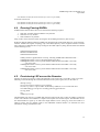
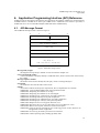
6.1. API Message Format
The NARB API message format is shown in Figure 8.
0
8
16
msg type
31
msg body len
ucid
msg sequence number
check sum
options
msg tag
msg body w/
sub stucture(s) and TLV(s)
Figure 8: NARB API message format.
Message Body Length
The length of message body in number of octets and must be multiple of 4.
Universal Client ID (UCID)
A 32-bit ID number to uniquely identify a NARB API client, which is used to track LSP owner by
the NARB.
Message Sequence Number
The number can be used to identify the LSP query context a message belongs to.
Check Sum
The arithmetic sum of the first three 32 bit words
Options
A bit mask to indicate client-specific requirements, here are explanations for some bits.
0x0000,0001: Using standard NARB CSPF request parameter format
0x0000,0002: Requesting all available VLAN tags.
0x0000,0004: Requesting all available VLAN wavelengths.
0x0000,0010: Excluding layer-1/optical-layer from path computation.
0x0000,0020: Excluding TDM layer from path computation.
0x0000,0040: Excluding layer-2/Ethernet-layer from path computation.
0x0000,0080: Excluding layer-3/IP-layer from path computation..
0x0001,0000: Request for all-strict hop path; otherwise, loose.
0x0002,0000: The above all-strict or loose-hop path is preferred; otherwise, a must
0x0010,0000: Bidirectional request; otherwise, unidirectional request
0x0020,0000: Using VLAN tag constraint for layer 2 LSP (tagged E2E VLAN); otherwise, an
untagged E2E VLAN if applicable.
0x0080,0000: A VLAN tag bit mask is passed as extra constraint.
0x0100,0000: Client requesting Query Holding (Q-Hold) mode.
18
NARB Design and User Manual v2.1b
April 2008
0x0200,0000: Client requesting Query Confirmation (Q-Conf) mode.
0x0400,0000: Returning Subnet ERO if any.
0x0800,0000: Returning Subnet DTL if any.
Message Tag
A 32-bit tag; when used with the 0x00200000 option, is the requested VLAN tag to constrain a
layer-2 LSP (0: no tag, the default value; 0xffff: any tag; otherwise: a specified tag in [1, 4095])
6.2. LSP Query Messages
The LSP queries and replies are distinguished by the message type and the body content. They are
described as follows.
6.2.1. Source Client LSP Query Request
The message type is MSG_APP_REQUEST (0x02). The message body structure is:
struct msg_narb_cspf_request
{
u_int32_t lspb_id;
u_int32_t app_seqnum;
struct in_addr area_id;
struct msg_app2narb_request app_req_data;
};
where the struct msg_app2narb_request uses the standard LSP request data format as indicated by the
option bit 0x0001 (see Section 6.1). The format is defined as follows.
struct msg_app2narb_request
{
u_int16_t type;
u_int16_t length;
struct in_addr src;
struct in_addr dest;
u_int8_t encoding_type;
u_int8_t switching_type;
u_int16_t gpid;
float bandwidth;
};
where type is TLV_TYPE_NARB_REQUEST (0x02).
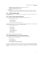
6.2.2. NARB-NARB Recursive LSP Query Request
The message type is MSG_ MSG_PEER_REQUEST (0x41). The message body is:
struct msg_narb_recursive_cspf_request
{
u_int32_t lspb_id;
u_int32_t app_seqnum;
struct in_addr area_id;
struct msg_app2narb_request app_req_data;
struct msg_app2narb_request rec_req_data;
};
There are two msg_app2narb_request blocks. The first, app_req_data, carries the original LSP request data
from the user application. The second, rec_req_data, carries the recursive LSP request data, which keeps
the progress of the multi-region (or multi-layer) path computation process that crosses boundary of
domains.
19
NARB Design and User Manual v2.1b
April 2008
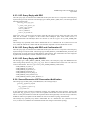
6.2.3. LSP Query Reply with ERO
The LSP query reply is returned to the NARB API client by the API server as a response to the LSP query
request message sent by the client. The message type is MSG_REPLY_ERO (0x21). The message has the
following message body.
struct msg_narb_cspf_reply
{
u_int32_t narb_apiserv_id;
u_int32_t app_seqnum;
struct in_addr src;
struct in_addr dest;
struct te_tlv_header tlv;
};
where narb_apiserv_id and seqnum are used to track the LSP query session. In the LSP query reply with
ERO, the tlv contains a sequence of IPv4 Prefix ERO Subobjects (RFC 3209 Section 4.3.3.3) or
Unnumbered Interface ID Subobject (RFC 3477 Section 4). The TLV type is TLV_TYPE_NARB_ERO
(0x03).
This message may optionally return either a Subnet ERO TLV or a Subnet DTL TLV (Sections 6.3.5 and
6.3.6) when the domain has a subnet and the user/client has requested to see the subnet ERO or DTL.
6.2.4. LSP Query Reply with ERO and Confirmation ID
The LSP query reply is returned to the NARB API client by the API server as a response to the LSP query
request message sent by the client. The message type is MSG_REPLY_CONFIRMATION_ID (0x24). The
message body is exactly the same as MSG_REPLY_ERO message. The confirmation ID is the simply the
original UCID and Sequence Number combined. No extra TLV is used.
6.2.5. LSP Query Reply with ERROR
The message type is MSG_REPLY_ERROR_CODE (0x22). The LSP query reply with ERROR has the
same message body structure, msg_narb_cspf_reply. The tlv is different with a 32-bit error code. The error
codes are listed below. The TLV type is TLV_TYPE_NARB_ERROR_CODE (0x04).
NARB_ERROR_NO_SRC (1)
NARB_ERROR_NO_DEST (2)
NARB_ERROR_NO_ROUTE (3)
NARB_ERROR_INTERNAL (4)
NARB_ERROR_INVALID_REQ (5)
NARB_ERROR_JUST_HOLDON (6)
NARB_ERROR_EXCEED_MAX_RETRAN (7)
6.2.6. Source/Recursive LSP Reservation Notification
The message type is MSG_APP_CONFIRM (0x03). The message body is:
struct msg_app2narb_confirm
{
msg_app2narb_request req;
te_tlv_header ero;
};
In the client/peer LSP reservation notification message, the NARB API client sends the original LSP
request data, msg_app2narb_request, to the server together with the ERO TLV that the server has returned.
This is to notify the NARB server that the requested LSP has been physically reserved (set up). Therefore,
NARB can follow up to update its LSP database as wells as its abstract topology advertisement.
This message may optionally carry either a Subnet ERO TLV or a Subnet DTL TLV (Sections 6.3.5 and
6.3.6), in which case NARB is also notified about link state changes in the subnet topology.
20
NARB Design and User Manual v2.1b
April 2008
6.2.7. Source/Recursive LSP Release Notification
The message type is MSG_APP_REMOVE (0x04). The client/peer LSP release notification has the exactly
same message body as the client/peer LSP reservation notification.
#define msg_app2narb_release msg_app2narb_confirm
This is to notify the NARB server that the reserved LSP has been released (torn down). Therefore, the
NARB can make changes accordingly.
6.2.8. LSP Release Confirmation
An LSP release confirmation is sent to the NARB API client by the server to indicate that the server has
received the client/peer LSP release notification message. The message type is
MSG_REPLY_REMOVE_CONFIRM (0x23) with an empty message body.
6.3. Optional TLVs
Several optional TLVs are used together with the above API messages. Some are mandatory when certain
message options are present.
6.3.1. LSP Broker ID TLV
The TLV type is TLV_TYPE_NARB_LSPB_ID (0x08). The value field contains a 32-bit unsigned number.
struct msg_app2narb_lspb_id
{
u_int16_t type;
u_int16_t length;
u_int32_t lspb_id;
};
A LSP broker ID is unique for every NARB instance. The LSP Broker ID TLV is passed along with LSP
Recursive query messages to downstream NARB such that the downstream NARB can track which
upstream NARB has sent the request.
6.3.2. VLAN Tag Mask TLV
The TLV type is TLV_TYPE_NARB_VTAG_MASK (0x05). The value field is a 4096 bit string stored in
a 512 bytes data array.
struct msg_app2narb_vtag_mask
{
u_int16_t type;
u_int16_t length;
u_char bitmask[MAX_VLAN_NUM/8];
};
VLAN Tag Mask TLV is mandatory when the message option bit 0x00800000 is set. It is passed along
with LSP Query and LSP Recursive Query messages that allow source client or upstream domains to
narrow down the range of VLAN tags available for downstream domains.
6.3.3. Suggested VLAN Tag TLV
The TLV type is TLV_TYPE_NARB_SUGGESTED_VTAG (0x07). The value field contains a 32-bit
unsigned number.
struct msg_app2narb_suggested_vtag
{
u_int16_t type;
u_int16_t length;
u_int32_t suggested_vtag;
21
NARB Design and User Manual v2.1b
April 2008
};
Suggested VLAN Tag TLV is passed along with LSP Recursive Query messages by upstream NARB to
ask downstream NARB to try the specified VLAN tag first. This is a technique to reduce the chance of
odds that downstream domains picks a VLAN tag that was not held by upstream domains and to be taken
by competing path computation sessions. This TLV is usually used in joint with the VLAN Tag Mask TLV
with the message option 0x0000,0002 being set.
6.3.4. Hop Back Interface TLV
The TLV type is TLV_TYPE_NARB_HOP_BACK (0x06). The value field contains an IPv4 address.
struct msg_app2narb_hop_back
{
u_int16_t type;
u_int16_t length;
u_int32_t ipv4;
};
A Hop Back TLV is used when signaling proceeds to the next-domain border router with a ULP or CLP
ERO and needs to expand the loose hops with the next-domain NARB. To calculate a local path starting
from the border router, NARB usually needs to know from which ingress TE link/interface the signaling
comes into this domain. Then NARB can return an ERO that provides sufficient information for the
signaling daemon to allocate labels and create an ingress-to-egress cross connect. The signaling daemon
passes the TE link/interface IP address to NARB via the Hop Back TLV.
6.3.5. Subnet ERO TLV
The TLV type is TLV_TYPE_NARB_SUBNET_ERO (0x09). The value field contains an ERO with the
same format as that in an ERO Reply message. The Subnet ERO TLV is returned when NARB has
computed a path across a subnet and the client/user wants to know the subnet physical hops (in addition to
the VLSR-level signaling hops in the main ERO).
6.3.6. Subnet DTL TLV
The TLV type is TLV_TYPE_NARB_SUBNET_DTL (0x0B).
Designated Transit List which is the equivalent of a subnet ERO.
The value field contains a Subnet
struct msg_narb_subnet_dtl
{
u_int16_t type;
u_int16_t length;
dtl_hop hops[1]; //actual number of dtl_hops depends on length
};
Each DTL hop contains a node name and outgoing link id in the following format.
struct dtl_hop
{
u_int8_t nodename[20]; //19-char C string;
u_int32_t linkid; //link ID number
};
Both Subnet ERO and DTL TLVs should not be requested and returned within the same message.
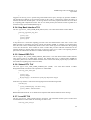
6.3.7. Local-ID TLV
The TLV type is TLV_TYPE_NARB_LOCAL_ID (0x0A). The value field contains a pair of 32-bit source
and destination local IDs. When one is missing, its value is zero.
struct msg_narb_local_id
22
NARB Design and User Manual v2.1b
April 2008
{
u_int16_t type;
u_int16_t length;
u_int32_t lclid_src;
u_int32_t lclid_dest;
};
The Local IDs are passed from client to NARB for review. NARB will pass them to RCE to constrain to
the edge interfaces represented by the local ID(s) if applicable. Currently only the subnet-interface type of
local IDs is accepted to apply path constraints.
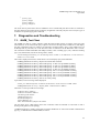
7. Diagnostics and Troubleshooting
7.1. NARB_Test Client
The NARB test client is a utility software within the narb-sw/narb package to perform some basic API
client functions. It can send an LSP query request to and receive the reply from a NARB server and display
the path computation result. For instance, the following command sends a query to the NARB server on
mcln-hopi-narb, at port 2609, for a LSP from the source 10.100.20.233 to the destination 140.173.4.232.
The constraints include bandwidth 1000 Mbps (-b1000), L2SC switching type (-x51), Ethernet encoding
type (-e2), bidirectional (-B) and VLAN tag 3020 (-v3020).
#/usr/local/dragon/sbin/narb_test -H mcln-hopi-narb -P 2609 -S 10.100.20.233 -D 140.173.4.232 b1000 -x51 -e2 -B -v3020
The result is displayed as follows, which shows a successful query reply with a full ERO.
NARB@[2006/05/02 10:20:47] : Request successful! ERO returned...
NARB@[2006/05/02 10:20:47] : HOP-TYPE [strict]: 10.100.15.38 [UnumIfId: (4,3020)]
NARB@[2006/05/02 10:20:47] : HOP-TYPE [strict]: 10.100.15.37 [UnumIfId: (4,3020)]
NARB@[2006/05/02 10:20:47] : HOP-TYPE [strict]: 10.100.10.38 [UnumIfId: (4,3020)]
NARB@[2006/05/02 10:20:47] : HOP-TYPE [strict]: 10.100.10.37 [UnumIfId: (4,3020)]
NARB@[2006/05/02 10:20:47] : HOP-TYPE [strict]: 140.173.97.54 [UnumIfId: (4,3020)]
NARB@[2006/05/02 10:20:47] : HOP-TYPE [strict]: 140.173.97.53 [UnumIfId: (4,3020)]
NARB@[2006/05/02 10:20:47] : HOP-TYPE [strict]: 140.173.97.86 [UnumIfId: (4,3020)]
NARB@[2006/05/02 10:20:47] : HOP-TYPE [strict]: 140.173.97.85 [UnumIfId: (4,3020)]
NARB@[2006/05/02 10:20:47] : E2E VLAN TAG [ 3020 ]
Upon failure, an error message will be displayed.
#./narb_test -H mcln-hopi-narb -P 2609 -S 10.100.70.233 -D 140.173.4.232 -b1000 -v3020
NARB@[2006/05/02 10:31:35] : Request failed : Unknown Source Address
The below is a list of possible error messages.
"Unknown Source Address"
"Unknown Destination Address"
"No Routing Path Found"
"NARB Internal Error"
"Invalid Path Request"
"System Warming Up"
"Max. Retransmission of Request Exceeded"
The first three errors could happen when some constraint cannot be satisfied or some node or link is
missing in the global or local topology.
“NARB Internal Error” usually means that an internal malfunction or some inter-module communication
pipe (e.g., NARB-RCE and NARB-NARB) is broken.
23
NARB Design and User Manual v2.1b
April 2008
“Invalid Path Request” usually means the request has unrealistic parameters/options or the API message
packet is corrupt, i.e., wrong length, wrong checksum or wrong format.
When “System Warming Up” is present, just wait for up to one minute for the system to finish initiation or
transition.
Below is a list of mostly used options:
-H host: NARB server host name or IP address (default = localhost)
-P port: NARB server port (default = 2609)
-S ip:
Source loopback IP address for the queried path.
-D ip:
Destination loopback IP address for the query
-U:
Unidirectional request (default = Bidirectional)
-b bw:
Bandwidth, float in Mbps
-x num: Switching type, number (default = 51, which means L2SC)
-e num: Encoding type, number (default = 2, which means Ethernet)
-v vtag: Specifying a VLAN tag in [1, 4095] for the queried path.
-V:
Using any available VLAN tag picked by NARB.
-a:
Showing all the available VLAN tags.
-k ip:
Hop back IP address (see Section 6.3.4)
-E num: Specifying excluded layers for the queried path, a number as bitmask (For instance, 3 = 0011
excludes Lambda and TDM layers)
-Q:
Query-Holding mode requested by client.
-C:
Query-Confirmation mode requested by client.
7.2. Log File
More information can be obtained from the system log file in /var/log/narb.log. From the log file, one can
tell whether a domain topology has been originated, whether the API client connection has be accepted,
whether RCE has returned a path computation result (if not, what the RCE error code is) and whether and
what partial explicit route has been returned from a peer NARB.
8. Conclusion
This document presents an installation and configuration guide to use the NARB and related software. It
intends to provide necessary information for users to deploy a multi-domain, multi-layer GMPLS network
control plane successfully. In this document, the NARB software is used in the context of the DRAGON
network. Users should also find it useful to customize the software into their own network control plane
implementation. Those interested in deploying the NARB and RCE components in their networks or the
DRAGON control plane in general should further refer to the following documents available at
http://dragon.east.isi.edu.
•
DRAGON Control Plane Overview
•
NARB and RCE Architecture
•
NARB Design and User Manual
24
NARB Design and User Manual v2.1b
April 2008
•
RCE Design and User Manual
•
VLSR Implementation Guide
•
DRAGON and HOPI Network Control Plane Guide
9. DRAGON Project
This document was generated by the University of Southern California (USC) Information Sciences
Institute (ISI) as part of the National Science Foundation funded Dynamic Resource Allocation via GMPLS
Optical Networks (DRAGON) project. Additional details regarding this project are available at
http://dragon.east.isi.edu.
25