1
Automatic Track Power Reversing - Now Standard "Your system was easy to
install, and has operated
flawlessly. I highly
recommend it!"
PRODUCT OVERVIEW
PTC Model III
Programmable
Turntable Controller
- Paul Scoles,
MMR and widely read Gazette and MR author.
"A very well made and
thought out system."
- Editor Bob Brown,
Narrow Gauge and Short Line Gazette, July/Aug 1996.
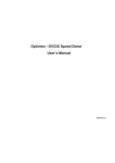
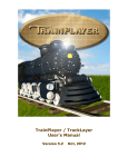
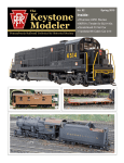
The PTC Model III Controller. Supports up to 99 selectable
tracks, over 14,000 indexing positions. Includes “Power On”
LED, Master Power Switch, and Step Cycle Indicator LEDs,
Deluxe Enclosure, and optional Track Power Reversing.
APPLICATIONS
The PTC Model III is designed for users wanting to solve
the problem of reliable turntable indexing. Situations
where the PTC Model III will be of benefit include:
•
•
•
•
Turntables with many lead and service tracks;
Turntables where the tracks are hard to see,
particularly those in corners or near the rear of the
layout, or those with dim lighting;
Layouts with high quality, highly detailed rolling stock
and bridge modeling where "hands off" indexing is
preferred;
Any situation where reliable, accurate indexing will
enhance layout operation and enjoyment.
"It's a clearly superior way
to control a turntable in any
model railroad scale"
- Editor Andy Sperandeo,
Model Railroader Magazine, December 1996.
PTC FEATURES
The PTC Model III includes all of the features needed
to accomplish highly reliable, accurate, and realistic
indexing operations:
•
•
•
•
•
•
•
•
•
•
•
•
•
•
•
•
Fully user programmable indexing for up to 12
tracks (standard)
Indexes both bridge ends
Expandable up to 24, 48, or 99 tracks
Track selection using rotary switch, pushbuttons,
or keypad
Automated track selection with C/MRI using the
optional Chubb/Universal Track Selector
Very fine 0.025º indexing resolution
Easy index programming
Select from 14,400 possible stopping locations
Automatic bridge track power polarity control
standard
High torque stepper motor with internal gearing
Heavy duty motor available for O and G scales
Quiet, smooth, slow operation
Programmable maximum speed: 0.15 to 0.50 RPM
Programmable momentum
No maintenance required
Simple, reliable installation- no sensors
PTC Model III, Product Overview and Ordering Information, Rev 1/05 - Page 1
The PTC Model III :
Turntable operation
like you've always
wanted.
OVERVIEW
The PTC Model III (Programmable Turntable Controller) is a user
programmable turntable indexing system for use in new or existing N,
HO, S, O, and G scale turntables.
The turntable's indexing positions are programmed into the PTC by the
user, who "teaches" the PTC where the lead and service track positions
are. The PTC does not use infrared diodes, tab stops, or any mechanical
methods for indexing. Once programmed, the PTC remembers the user's
track locations-- even when the system power is turned off. During
operation, the user selects the desired lead or service track from the
control panel. The PTC automatically determines the shortest direction
of travel, simulates turntable momentum by ramping up the bridge to a
user-determined maximum speed, then ramps it down as it approaches
the desired service or lead track location. The PTC then stops the bridge
at the exact location desired, within 0.015º.
The PTC Model III system is comprised of five primary components: the
Controller, Track Selector Module, Stepper Motor, Motor Mount Kit
(optional), and Power Supply.
mounted in the user's control panel, with the switch positions lining up
to the track indications on the track schematic.
Alternatively, the PTS is designed to enable users to select desired
tracks by using individual pushbuttons, which are individually wired to
the PTS. You supply the pushbuttons to match existing buttons on the
your layout schematic, or purchase Pushbutton Switch Packs. The
standard PTS supports selection from 2 to 12 tracks. The switches are
situated one per service or lead track, with the desired track selected by
pushing the specific button on the control panel track schematic. The
PTS is expandable to support up to 36 tracks; see Options.
Like the PTS, the CTS is designed to use pushbuttons but has additional
track capacity (24 tracks). In addition, it has additional signal inputs
and outputs to interface the controller to computer based control systems
such as those utilizing the Chubb C/MRI protocol. If you are using a
Chubb USIC or C/MRI type computer control, the inputs and outputs of
the C/MRI can be used to emulate the action of the pushbutton switches,
as well as the action of the Head/Tail and Run/Stop switches. Request
(or download) Application Note #3, "PTC Computer Interfacing" for
details on accomplishing this.
Three other functions are common to the RTS, PTS, and CTS selectors:
•
•
•
A Head/Tail toggle switch. The Head/Tail switch tells the
controller which end of the bridge you want lined up with the
selected track-- the head end or the tail end.
A Start/Stop momentary push button switch. The Start/Stop switch
initiates bridge movement following track selection, and also
provides a "panic button" stop function if the bridge is in motion.
A Status Indicator. The Status Indicator is a red/green bi-color
LED that provides feedback to the user as to what mode the
controller is in while in operation. It also provides confirmation
indications during the setup and programming of the controller.
The RTS, PTS, and CTS selectors support 4 standard speed and
momentum ranges.
SYSTEM DESCRIPTION
PTC Controller.
The controller uses an embedded microprocessor with on board software
to learn about and control the user's turntable. The controller receives
track selection information from the Track Selector Module and
intelligently controls the turntable bridge position (indexing) via a DC
stepper motor. Additionally, the user can also program different levels
of simulated momentum and different maximum speeds.
♦ Option: The controller can automatically control track power
polarity to the bridge rails, reversing track power whenever the bridge
turns +/- 90° from the reference track, or whenever the bridge turns +/90° from the starting point of any move. This option is called Automatic
Track Power Reversing (“ATR”). This feature is designed to eliminate
the need for a split ring rail, split rail commutator or separate power
reversing toggle switch. Rail power is routed through the Controller,
which has a reversing relay inside.
♦ Option: Pushbutton Track Selector Expansion. If you are using the
Pushbutton Track Selector Module, you can expand the track selection
capability by 24 tracks by adding a Track Selector Expansion Module.
The Track Selector Expansion Modules do not include the toggle
switch, pushbutton switch, and LED found on the base module. One
additional Expansion Module can be added to the 12 track PTS or 24
track CUS to achieve capacities up to 36 or 48 tracks, respectively.
♦ Option: Diamond Scale® Rotary Selector Conversion. If you
currently have a Diamond Scale® system equipped with a "dual stack"
rotary switch used for simultaneous indexing and turntable track power
control, it is possible to convert the switch for use with the PTC Model
III, if desired. The indexing deck of the switch is wired to a Pushbutton
Track Selector Module, or the Chubb/Universal Track Selector if doing
24 tracks. On the order form, order a Pushbutton Selector (or the
optional Chubb/Universal Track Selector) and request (or download) a
copy of Application Note #1, "Diamond Scale® Rotary Switch
Conversion".
Track Selector Modules.
The PTC Model III Controller receives track selection information from
the Track Selector Module. There are four track selector module types: a
12 track Rotary Track Selector Module (abbreviated RTS), a 12 track
Pushbutton Track Selector Module (abbreviated PTS), a 24 track
Chubb/Universal Track Selector Module (abbreviated CTS), and a 99
track Keypad Track Selector Module (abbreviated KPS).
The RTS uses a 12 position rotary switch (supplied) to provide
selection capability from 2 to 12 tracks. Typically, the rotary switch is
“The PTC turntable controller is very elegant
in design and provides excellent and accurate
turntable indexing. It features a good user
interface and installs easily…
the PTC is a very good solution.”
- Editor and MMR Doug Geiger, Model Railroading, August 2000
PTC Model III, Product Overview and Ordering Information, Rev 1/05 - Page 2
The PTC is available with two high quality motor options, both capable
of superior accuracy and long life: a Standard Motor applicable to most
installations, and a Heavy Duty Motor for larger "O" and "G" gauge
applications. The heavy duty motor features larger motor windings and
heavier gearing. If your turntable bridge is O scale or larger and your
bridge is longer than 18", use of the heavy duty motor is recommended.
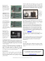
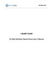
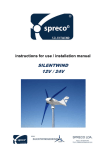
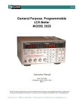
Rotary Track Selector
Module (RTS). Shown with
Head/Tail Switch, Status
LED, and Run/Stop Switch;
2.5" wide x 5" long. Supports
12 selectable tracks, 4 speed
ranges, and 4 momentum
ranges.
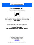
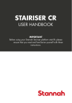
Figure 1:
Microstepping
Motors,
Standard and
Heavy Duty
(0.025° base
step angle)
Pushbutton Track Selector
Module (PTS). Also shown
with Head/Tail Switch, Status
LED; and Run/Stop Switch.
2.5" x 5". Requires pushbutton
switches (optional). Supports
12 selectable tracks (expandable to 48), 4 speed ranges,
and 4 momentum ranges.
24 Track Chubb/Universal
Track Selector Module (CTS).
Shown with Head/Tail Switch,
Status LED, Run/StopSwitch,
and computer interface
connection terminals. 2.5" x
5". Requires pushbutton
switches (optional) or
computer driver and receiver
modules (customer supplied).
Supports 24 selectable tracks, expandable to 48. Supports 4 speed ranges, and 4
momentum ranges.
Keypad Track Selector
Module (KPS). Includes soft
green Dual Digit Numeric
Display, Status Indicator
LED, 12 Key Keypad, and
Integral Mounting Panel.
Supports up to 99 selectable
tracks, 10 speed ranges, 10
momentum ranges, and
alphanumeric status
feedback.. 3.8” x 6”.
The motor gearhead mounting dimensions are the same for both motors:
approximately 2.4” square. Overall dimensions are 2.4” square by 2.8”
long for the Standard Motor; 2.4” square by 3.5” long overall for the
Heavy Duty Motor. The dimensions include the 1” long, ¼” diameter
shaft. Both motors are supplied with 24” leads.
For larger scales and turntable installations that may have curved lead
tracks we have integrated an optional shaft brake. Although in most
applications this is not an issue, we do recognize that in the larger scales
and longer bridges it can be a problem. The problem stems from gear
backlash internal to the motor. To solve this we have added an output
on the controller that drives a power off shaft brake. The motor shaft
runs through this device and it is controlled by the PTC III, effectively
holding the bridge immobile. The mounting insturctions with photos are
available on the www.nyrs.com website.
We have also added a set of dry contacts for the user to use as he
pleases. These contacts are closed when the motor is running to facilitate
a sound module or lights to be switched on when the turntable is
turning.
The KPS (Keypad Selector) features a telephone style keypad, a status
indicator LED, a soft green dual digit display for indicating the current
track location, and an integrated mounting panel. The KPS can index up
to 99 tracks in its standard configuration, as well as provide 10 speed
and momentum ranges. The KPS is an upgrade option to the standard
controller configuration.
Note that the overall minimum and maximum speeds achievable by the
controller are the same for all selectors (0.15 to 0.50 RPM). The
Keypad Selector simply provides more selectable ranges. The same
applies to momentum simulation: the minimum and maximum
momentum periods are the same, the Keypad Selector simply provides
more selectable ranges between minimum and maximum.
DC Stepper Motor.
Stepper motors have the unique capability to stop at pre-defined angular
increments ("steps"). This is unlike a regular DC motor that rotates
freely with no particular angular control or stopping position. This
stepping capability provides the motor with a high degree of repeatable
positional accuracy.
Another new feature is an RS-232 comm port. In the future we will offer
a power routing unit that will route the power for your turntable leads so
the power will be routed to only the lead that the bridge is pointed to.
The power routing unit and the PTC controller will communicate
through this port.
Power Supply.
The Power Supply provides +12VDC power to drive the controller,
track selectors, and stepper motor. The Power Supply plugs into a USA
standard 115VAC outlet but now accepts up to 220v for international
customers.
You can download this overview, User Manuals, Application
Notes, and other information from our web site at
www.nyrs.com
PTC Model III, Product Overview and Ordering Information, Rev 1/05 - Page 3
♦ Option: If you are using the Rotary Track Selector Module and your
panel is thicker than 1/8", or you do not want to drill the hole pattern
yourself, a pre-drilled front panel is available. The panel is supplied
plain; you finish and letter it to match your layout.
INSTALLATION CONSIDERATIONS
There are a few considerations in determining if the PTC Model III can
be installed on your layout:
•
The size of your turntable and its shaft
•
Installation of the motor to the turntable shaft
•
Installation of the Track Selector controls in the layout control
panel, and
•
Programming of the PTC Controller.
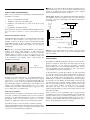
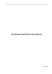
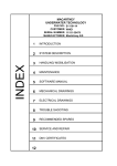
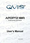
Cable Length. The PTC comes standard with cable lengths suitable for
most turntables, which are generally less than 3' feet from the layout
front panel. The location relationship of the different components is
shown in Figure 3:
Layout
Front
Panel
Turntable
M otor - 2' Cable
These activities are discussed in detail in the PTC Model III Installation
Instructions and User's Manual, so only an overview will be provided
here.
Controller
Turntable Size, Turntable Shaft Size
The PTC Model III can be installed on any turntable with a center shaft
accessible for direct connection to the stepper motor, up to 30",
including products from Diamond Scale Construction®, Bowser®,
Model Masterpieces®, and others. The PTC is supplied with a high
quality clear anodized standard shaft coupling; see order sheet for
available sizes.
Track Selector - 3' Cable
Power Supply - 6' Cable
Figure 3: Cabling Lengths
♦ Option: If you are using the Walthers® turntable, order the Walthers
Turntable Shaft Adaptor, which includes a 1" shaft extension and
application note describing the modifications necessary to extend the
turntable shaft for connection to the motor (Application Note #3,
"Walthers® Turntable Adaptor Installation"). Installation will be easier
if the modifications are completed prior to final assembly and
installation of the turntable.
Figure 2:
Standard Shaft Couplers
Motor Installation.
In addition to the shaft coupler, the motor is supplied with hardware for
mounting the motor to a support system. The actual motor support
system can be one you design (the User Manual includes full motor
dimensions) or you can use the optional Basic Motor Mount Kit. The
Motor Mount Kit includes a machined bracket with hardware and is
suitable for most turntables with pit diameters up to 18”, or larger
turntables if the pit bottom is sufficiently sturdy to support the motor
(3/8" or thicker plywood or particle board).
Track Selector Installation.
The Track Selectors are intended to be mounted in your layout's existing
front panel. The Rotary and Pushbutton selectors can be mounted in
panels up to 1/8" thick, although a thickness of 1/16" is recommended.
The Keypad selector can be mounted in panels up to ¾” thick.
Templates are supplied for locating necessary mounting hole patterns.
♦Option: If your layout requires longer cables, optional 6' and 10'
Controller-to-Track Selector and 3', 6', and 10' Controller-to-Motor
cables are available.
PROGRAMMING
Programming the PTC Model III with your track's locations involves
putting the controller in "Learn Mode" and single stepping the bridge
through a full circle. As you "single step" the bridge, you indicate
where the track locations are, and the PTC remembers them. You also
select the maximum speed and momentum you want. The system is
reprogrammable if you add more tracks later on.
An important feature of the PTC Model III has to do with programming
of your bridge’s stopping points. Although many bridges are identical at
both ends, most are not-- the tracks do not line up exactly through the
center of the turntable, and are frequently offset. In addition, most
turntables have concentricity or other manufacturing variances that must
be compensated for. The PTC has the unique ability to learn where the
correct locations are for positioning both the so-called “head end” and
“tail end” of the bridge. In this way, the PTC treats the head and tail
ends of the bridge locations "separately" and their respective
concentricity and offset errors are accounted for automatically.
Operations like full 180 degrees turns from any track location are easily
achievable, and reliable.
Lastly, note that no real "programming" skill is required, and all
programming control is done through the Track Selector Module. The
only thing really necessary for successful programming is access to the
turntable to view the track and bridge alignments up close-- plus a
smoothly operating turntable. Full instructions are included in the User's
Manual. Programming takes about 10 to 15 minutes.
For the Rotary Selector, a four hole pattern is required for the Rotary
Switch, the Head/Tail Switch, the Status LED, and the Run/Stop Switch.
The Pushbutton Selector requires a 5 hole pattern, plus whatever holes
you need for the actual track selection pushbuttons.
PTC Model III, Product Overview and Ordering Information, Rev 1/05 - Page 4
FREQUENTLY ASKED QUESTIONS
Here are answers to some of the most frequently asked questions
regarding the PTC Model III. Additional Frequently Asked Questions
can be found on our web site at www.nyrs.com.
Q: TRACK SENSING. What does your system use to index (what
kind of switches or sensors)?
A: This is an important point: no sensors are used! The PTC Model III is
unique in that is does not use mechanical or optical sensors of any kind,
and therefore, much easier to install. There is no need to build or mount
sensor brackets, sensors, or any of the associated hardware and wiring.
As a result, the system is completely maintenance free.
Q: PROGRAMMING THE SYSTEM. Do I need any programming
skill to program the system? Do I need to use a PC?
A: No. All programming is done through the standard operating
controls-and no actual "programming" experience is needed.
Programming takes about 5 to 10 minutes, depending on the number of
tracks you have.
Q: SYSTEM MEMORY. Does power need to be "on" all the time to
keep the programming stored?
A: No, the system uses a non-volatile memory.
Q: WHICH TRACK SELECTOR SHOULD I USE? You have
several Track Selector Modules available... how do I choose which one
is best for me?
A: We offer several selectors primarily to satisfy the varied requests for
functionality we have received over the years. For the most part, the
track selector that is best for you is a matter of personal operating
preference. To start, identify how many tracks you will ultimately be
indexing, and then decide if you have a preference for using rotary
switches, pushbutton switches, or keypad buttons for operation. Then,
you can narrow your selection:
If you have less than 12 tracks to index, then the standard Rotary or
Pushbutton Selectors will probably be your best choice. The
Rotary is the easiest to install, and the most intuitive. The
Pushbutton Selector is designed to work with an array of discrete
momentary pushbuttons, one for each track (you supply your own
momentary pushbuttons, or purchase NYRS Switch Packs).
If you have up to 24 Tracks, then the Chubb/Universal Selector
will be a good choice. You would also choose the
Chubb/Universal if (a) you want to interface your turntable
controller to an automatic Chubb control system, or (b) If you
want to index more than 24 tracks (up to 48 tracks) using
pushbuttons, or (c) if you have an existing 24 position rotary
switch (like the double stack rotary switch supplied by Diamond
Scale) and you want to use it with the PTC.
Choose the Keypad Selector if you have more than 12 tracks to
index (up to 99 tracks), and you don’t want to go with the
Pushbutton route. The Keypad selector is more ‘hi-tech’ looking,
and comes supplied with a 12 key keypad, dual digit display, and
integrated face plate included. The Keypad Selector has the added
convenience of enabling the operator to change speed, momentum,
and ATR modes from the operating keypad, rather than by DIP
switches on the controller as is the case with the Rotary,
Pushbutton, and Chubb/Universal selectors.
WARRANTEE
The PTC Model III system is warranted against defects in material and
workmanship for a period of 1 year. If your system develops any
problems, New York Railway Supply will repair or replace your system
at no charge to you. This warrantee is void if the system has been used
outdoors, if the system has been used or modified with other than the
recommended options, or if the controller enclosure has been opened.
SPECIFICATIONS
Controller
Dimensions
5½"L x 5¼"W x 2"H
Selectable Tracks (standard)
12 tracks
Selectable Tracks (maximum, Chubb/Universal Selector) 48 tracks
Selectable Tracks (maximum, Keypad Selector)
99 tracks
Indexing Positions possible
Reversing Relay Rating (optional)
14,400
1.5 Amps (max)
Microstepping Motor
Motor Dimensions (Standard)
Motor Dimensions (Heavy Duty)
(Motor dimensions include shaft length)
Motor Shaft
Turntable Shaft Diameter
Turntable Shaft Length (Coupling Surface)
Step angle
Torque
Track Selector Modules
Dimensions
Rotary, Pushbutton, & Univ. Sel.
Keypad Selector
2.4" square x 2.8" long
2.4" square x 3.5" long
1/4" diam. x 1.0" long
1/8" to 1/2"diam.
1/4" long (min)
0.025° base step
400 oz.-in., minimum
5.0" L x 2.5" W x 0.75" H
6.0" L x 3.8" W x 1.0" H
Power Supply - Wall plug-in style
Input Rating
Output Rating (under load)
115-230VAC
12VDC @ 1.5A
Cabling
Control panel (track selector) to controller
Controller to stepper motor
Controller to power supply
Turntable Pit Diameter
For Basic Motor Mount Kit, Standard Installation
(Note: motor mount bracket may optionally be
mounted to pit bottom for larger turntables)
3 ft
2 ft
6 ft
18" max.
FOR MORE INFORMATION
This document and others are available in downloadable Adobe®
Acrobat format form our web site, or call or write us at:
NEW YORK RAILWAY SUPPLY
13225 Thornton Dr Westlake, TX 76262
Tel: (817)233-5068, Fax: (682) 831-0419
Web: www.nyrs.com Email: [email protected]
PTC Model III, Product Overview and Ordering Information, Rev 1/05 - Page 5