1
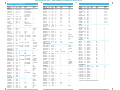
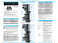
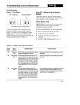
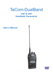
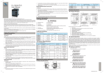
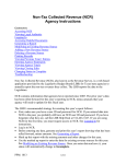
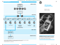
efesotomasyon.com - Allen Bradley,Rockwell,plc,servo,drive
Programming System
OPERATOR LEVEL
Power-Up &
Status Display
or
or
or
1305 Adjustable
Frequency AC Drive
or
Reference Guide
FRN 6.01 and Up
"Choose Mode"
MODE LEVEL
Display
(Read Only)
Process
Process Display
Program ➀
(Read/Write)
EEPROM ➀
Reset Defaults
Recall Values
Save Values
Upload Parameters ➂
Download Parameters ➂
Search ➁
(Read Only)
Control
Status ➁
Password
Control Logic ➀,
Fault Queue
Login,
Logout
Modify
GROUP LEVEL
Parameter Groups
(See Parameter List)
PARAMETER LEVEL
Parameters
(See Parameter List)
ATTENTION: This publication is designed as a reference
tool. The 1305 User Manual (publication 1305-5.2) must
be consulted for more detailed information about parameters, faults and hazards of personal injury.
➀ Access to the Program and EEPROM modes, and the Control Logic and Clear Fault Queue, are disabled if the password is Logged Out.
➁ Series A HIM Software Version 3.00 & Above or Series B HIM Software Version 1.01 & Above Only.
➂ Series B HIM Software Version 1.01 & Above Only.
Publication 1305-5.2.2 – July, 1996
P/N 41052-100-01(B)
efesotomasyon.com - Allen Bradley,Rockwell,plc,servo,drive
1305 Series C Parameter List
Group/
Parameter
Metering
Output Current
Output Voltage
Output Power
DC Bus Voltage
No.
Units
Min.
Value
Max.
Value
Default
Value
54
1
23
53
0.01 Amps
1 Volt
0.01 kW
1 Volt
0.00
0
0.00
0
—
—
—
0.01 Hz
0.01 Hz
0.01 Hz
1 deg. C
Numeric
1%
1%
0.00
0.00
0.00
0
0
0
0
2x Drive Output Curr.
Maximum Voltage
2x Rtd. Dr. Output Pwr.
410 - 230V Drive
815 - 460V Drive
Maximum Freq.
+400.00
400.00
100
Max Fault No.
200% Drive Rtd. Pwr.
200% Rtd. Dr. Out. Curr.
Text ➀
Text ➀
0.1 Sec
0.1 Sec
1 Hz
1 Volt
1 Volt
1 Hz
1 Hz
Text ➀
1%
Text ➀
0.1 Amps
1%
Text ➀
—
—
0.0
0.0
40
25% of DRV
25% of DRV
0
40
—
20% of DRC
—
20% of DRC
0% of DRC
–
—
—
3600.0
3600.0
400
100% of Max DRV
110% of Max DRV
120
400
—
150% of DRC
—
115% of DRC
150% of DRC
–
Three Wire
Adapter 1
10.0
10.0
60
Max DRV
Max DRV
0
60
Ramp
150% of DRC
No Derating
115% of DRC
0% of DRC
Enabled
1 Hz
1 Hz
1 Hz
1 Volt
1 Hz
1 Volt
1 Volt
Text ➀
1 Volt
1 Volt
0.1 kHz
Text ➀
Text ➀
Text ➀
0.1 Sec
1 Volt
Text ➀
Text ➀
Text ➀
0
40
40
25% Max DRV
0
0
25% Max DRV
—
0
0
2.0
—
—
—
0.0
0
—
—
—
120
400
400
100% of Max DRV
120
50% of Max DRV
110% of Max DRV
—
25% of Max DRV
25% of Max DRV
8.0
—
—
—
150.0
25% of Max DRV
—
—
—
0
60
60
Max DRV
30
Dr. Size. Dep.
Max DRV
Break Point
Dr. Size Dep.
0
4.0
Disabled
Stop/Fault
Ramp
0.0
0
Disabled
Induc/Reluc
Comp
Text ➀
Text ➀
0.1 Hz
Text ➀
Text ➀
0.1 Sec
0.1 Sec
—
—
0.0
—
—
0.0
0.0
—
—400.0
—
—
3600.0
3600.0
Adapter 1
Remote Pot
10.0
Preset
Disabled
5.0
5.0
Output Freq.
66
Freq. Command 65
MOP Hz
42
Drive Temp
70
Last Fault
4
% Output Power 3
% Output Curr. 2
Setup
Input Mode
21
Freq Select 1
5
Accel Time 1
7
Decel Time 1
8
Base Frequency 17
Base Voltage
18
Maximum Voltage 20
Minimum Freq 16
Maximum Freq 19
Stop Select
10
Current Limit
36
Overload Mode 37
Overload Current 38
Sec Curr Limit 141
Adaptive I Lim 149
Advanced Setup
Minimum Freq 16
Maximum Freq 19
Base Frequency 17
Base Voltage
18
Break Frequency 49
Break Voltage 50
Maximum Voltage 20
DC Boost Select 9
Start Boost
48
Run Boost
83
PWM Frequency 45
Analog Invert
84
4-20mA Loss Sel 81
Stop Select
10
DC Hold Time 12
DC HoId Volts 13
DB Enable
11
Motor Type
41
Compensation 52
Frequency Set
Freq Select 1
5
Freq Select 2
6
Jog Frequency 24
Prst/2nd Accel 26
Upper Presets 72
Accel Time 2
30
Decel Time 2
31
—
—
0.00
—
—
—
—
—
Group/
Parameter
No. Units
Frequency Set - continued
Preset Freq 1
27
0.1 Hz
Preset Freq 2
28
0.1 Hz
Preset Freq 3
29
0.1 Hz
Preset Freq 4
73
0.1 Hz
Preset Freq 5
74
0.1 Hz
Preset Freq 6
75
0.1 Hz
Preset Freq 7
76
0.1 Hz
Skip Freq 1
32
1 Hz
Skip Freq 2
33
1 Hz
Skip Freq 3
34
1 Hz
Skip Freq Band 35
1 Hz
MOP Increment 22
1 Hz/Sec
Analog Filter
144
Text ➀
Feature Select
Run On Power Up14
Text ➀
Reset/Run Tries 85
Numeric
Reset/Run Time 15
0.1 Sec
S Curve Enable 57
Text ➀
S Curve Time 56
0.1 Sec
Language
47
Text ➀
Cable Length
143
Text ➀
Rated Slip
146
0.1 Hz
Slip Comp Adder 148
0.01 Hz
IR Comp %
147
1%
Output Configuration
Output 1 Config 90
Text ➀
Output 2 Config 91
Text ➀
Analog Out Sel 25
Text ➀
Above Freq Val 77
1 Hz
Above Curr Val 142
1%
Faults
Fault Buffer 0
86
Numeric
Fault Buffer 1
87
Numeric
Fault Buffer 2
88
Numeric
Fault Buffer 3
89
Numeric
Clear Fault
51
Text ➀
Cur Lim Trip En 82
Text ➀
Line Loss Fault 40
Text ➀
Flt Clear Mode 39
Text ➀
Diagnostics
Drive Command 58
Byte
Drive Status
59
Text ➀
Drive Alarm
60
Byte
Input Status
55
Byte
Freq Source
62
Text ➀
Freq Command 65
0.01 Hz
Drive Direction 69
Text ➀
Motor Mode
43
Text ➀
Power Mode
44
Text ➀
Drive Type
61
Numeric
Firmware Ver. 71
Numeric
Output Pulses 67
1 Cycle
Drive Temp
70
1 deg. C
Set Defaults
64
Text ➀
Min.
Value
Max.
Value
Default
Value
0.0
0.0
0.0
0.0
0.0
0.0
0.0
0
0
0
0
0.00
—
400.0
400.0
400.0
400.0
400.0
400.0
400.0
400
400
400
15
255.00
—
10.0
20.0
30.0
40.0
50.0
60.0
0.0
400
400
400
0
1.00
100%
—
0
0.5
—
0.0
—
—
0.0
0.00
0%
—
9
30.0
—300.0
—
—
5.0
5.00
150%
Disabled
0
1.0
Disabled
0.0
Approp. Lang.
Short
2.0
—
Drv. Depend.
—
—
—
0
0% of DRC
—
—
—
400
150% of DRC
Faulted
Running
Frequency
0
0% of DRC
—
—
—
—
—
—
—
—
—
—
—
—
—
—
—
—
—
—
—
—
Ready
Default Run
F03 Enable
Enabled
—
—
—
—
—
0.00
—
—
—
—
—
0
0
—
—
—
—
—
—
400.00
—
—
—
—
—
65535
100
—
—
—
—
—
—
0.00
Forward
—
—
—
—
—
—
Ready
Group/
Parameter
No.
Masks
Logic Mask
92
Direction Mask 94
Start Mask
95
Jog Mask
96
Reference Mask 97
Accel Mask
98
Decel Mask
99
Fault Mask
100
MOP Mask
101
Local Mask
93
Owners
Stop Owner
102
Direction Owner 103
Start Owner
104
Jog Owner
105
Reference Owner 106
Accel Owner
107
Decel Owner
108
Fault Owner
109
MOP Owner
110
Local Owner
137
Adapter I/O
Data In A1
111
Data In A2
112
Data In B1
113
Data In B2
114
Data In C1
115
Data In C2
116
Data In D1
117
Data In D2
118
Data Out A1
119
Data Out A2
120
Data Out B1
121
Data Out B2
122
Data Out C1
123
Data Out C2
124
Data Out D1
125
Data Out D2
126
Process Display
Process Par
127
Process Scale 128
Process Text 1 129
Process Text 2 130
Process Text 3 131
Process Text 4 132
Process Text 5 133
Process Text 6 134
Process Text 7 135
Process Text 8 136
Units
Min.
Value
Max.
Value
Default
Value
Byte
Byte
Byte
Byte
Byte
Byte
Byte
Byte
Byte
Byte
—
—
—
—
—
—
—
—
—
—
—
—
—
—
—
—
—
—
—
—
01111111
01111111
01111111
01111111
01111111
01111111
01111111
01111111
01111111
01111111
Byte
Byte
Byte
Byte
Byte
Byte
Byte
Byte
Byte
Byte
—
—
—
—
—
—
—
—
—
—
—
—
—
—
—
—
—
—
—
—
—
—
—
—
—
—
—
—
—
—
Numeric
Numeric
Numeric
Numeric
Numeric
Numeric
Numeric
Numeric
Numeric
Numeric
Numeric
Numeric
Numeric
Numeric
Numeric
Numeric
0
0
0
0
0
0
0
0
1
1
1
1
1
1
1
1
149
149
149
149
149
149
149
149
149
149
149
149
149
149
149
149
0
0
0
0
0
0
0
0
1
1
1
1
1
1
1
1
Numeric
Numeric
ASCII txt
ASCII txt
ASCII txt
ASCII txt
ASCII txt
ASCII txt
ASCII txt
ASCII txt
1
-327.68
—
—
—
—
—
—
—
—
149
+327.67
—
—
—
—
—
—
—
—
1
+1.00
?
?
?
?
?
?
?
?
➀ Refer to 1305-5.2 User Manual, Appendix B, Table B.5.
efesotomasyon.com - Allen Bradley,Rockwell,plc,servo,drive
Power Terminal Block TB1 Designations
Terminal Block TB2 Designations
General Three Wire
Remote Pot
GRD
GRD
L1
R
L2
S
L3
T
+DC
BRK ➀
(–DC)
T1
U
T2
V
T3
W
0-10V
Dynamic Brake
Option
To Motor ➃
To Motor ➂
Required
Input Fusing
Required Branch
Circuit Disconnect
➄
AC Input Line ➁
➀
Source
2
Wiper or 0-10V DC Input
3
Common
4
4-20mA Input
5
0-10V Output
6
Start ➂
7
Common
8
Stop ➂
9
User Side
➀ Connection for Dynamic Brake Resistors for all models except the 200-230 Volt, 0.37
to 0.75 kW (0.5 to 1 HP) drive.
Important: The [DB Enable] parameter must be enabled for proper operation.
➁ For single phase applications, the AC input line can be connected to any two of the
three input terminals R, S, T (L1, L2, L3).
➂ 1305 drives are UL listed and CSA certified as a motor overload protective device. An
external overload relay is not required for single motor applications.
Important: This drive is not intended for use with single-phase motors.
➃ Ground from drive to motor frame must be an independent continuous insulated wire
run.
1
➀➃
U, V, W (T1, T2, T3)
Description
Earth Ground
AC Input Line Terminals
Dynamic Brake Option – Refer to
instructions included with option
Motor Connection
11
Enable ➂
12
Common
13
Reverse ➂
14 Jog ➂
15 Common
TB1 Terminal Designations
Terminals
GRD
R, S, T (L1, L2, L3)
+DC, BRK (or –DC)
Output #1
10
16
SW1 ➂➅
17
SW2 ➂➅
18
SW3 ➂➅
19
24VDC Source
(User Supplied)
20
(Sink)
Output #2
General Run Fwd/Rev
TB2 Terminal Descriptions
No.
1, 2, 3
2, 3
4, 3
5, 3
6, 7
8, 7
9, 10
11, 12
13, 12
14, 15
16, 15
17, 15
18, 15
19, 20
Signal
External Speed Pot
0-10V Analog Input
4-20mA Analog Input
0-10V Analog Output
Start
Stop
Programmable Output 1
Specification
10 kΩ Potentiometer, 2 Watts
Drive Input Impedance = 100 kΩ
Drive Input Impedance = 250 Ω
Meter Impedance ≥ 4 kΩ
Contact Closure Input ➂
Contact Closure Input ➂
Resistive Rating=115V AC/30V DC, 5A
Inductive Rating = 115 VAC/30 VDC, 2A
Drive Enable
Contact Closure Input ➂ ➃
Reverse
Contact Closure Input ➂
Jog
Contact Closure Input ➂
SW1
Contact Closure Input ➂
SW2
Contact Closure Input ➂
SW3
Contact Closure Input ➂
Programmable Output 2 24V DC ±20%, 50 mA Max. (Sink)
➀
➁
➂
➃
Required to operate drive. STOP also used to clear a fault.
Use HIM Stop button to clear faults.
Contact Closure Input. Internal 5V supply. DO NOT apply external voltage.
When the ENABLE signal is lost, the drive output immediately shuts off and the motor
will coast to a stop.
➄ A Start command will override any Jog command.
➅ See 1305 User Manual (publication 1305-5.2) for input configurations based on the
setting of parameter 21 - [Input Mode].
Faults
Diag C Lim FauIt
F36
Drive -> HIM
Remote Pot
Input Fusing
ATTENTION: The drive does not provide branch
circuit protection. Specifications for the recommended fuse size and type which provide branch circuit
protection against short circuits are provided below.
Branch circuit breakers or disconnect switches cannot
provide this level of protection for drive components.
Maximum Recommended AC Input Line Fuse
UL Class J, T, CC, or BS88 (or equivalent)
Three-Phase
Rating
kW (HP)
0.37 (0.5)
0.55 (0.75)
0.75 (1)
1.5 (2)
2.2 (3)
4.0 (5)
Single-Phase
Rating
kW (HP)
0.19 (0.25)
0.37 (0.5)
0.55 (0.75)
0.75 (1)
1.5 (2)
–
Run Forward
Jumper ➀➁
User Side
!
0-10V
Jumper ➀➃
Fuse
200-230V Rating
6
6
10
15
25
–
Fuse
380-460V Rating
3➀
3➀
6➁
10 ➁
15 ➁
20 ➁
➀ Must be dual element time delay, Bussmann LPJ or equivalent.
➁ If fuse blowing is a problem, use dual element type fuses.
Run Reverse
1
Source
2
Wiper or 0-10V DC Input
3
Common
4
4-20mA Input
5
0-10V Output
6
Start ➂
7
Common
8
Stop ➂
9
EEprom Fault
F32
Hz Err Fault
F29
Output #1
10
11
Enable ➂
12
Common
13
Reverse ➂
14 Jog ➂
15 Common
24VDC Source
(User Supplied)
Drive Reset FauIt
F22
16
SW1 ➂➅
17
SW2 ➂➅
18
SW3 ➂➅
19
20
(Sink)
Output #2
Hz Sel Fault
F30
HIM -> Drive
The drive output current has exceeded the software [Current Limit] and the [Cur Lim Trip En]
parameter was enabled.
The checksum read from the HIM’s EEPROM
does not match the checksum calculated from
the EEPROM data.
Occurs on power-up. Caused by having the START
Input (or RUN Input) closed, with the STOP Input
open and [Run On Power Up] = DISABLED.
EEPROM has invalid data or can not be
programmed to valid data.
This fault indicates that there is not a valid operating frequency. It can be caused by:
1. [Maximum Frequency] is less than
[Minimum Freq].
2. Skip frequencies and skip bandwidth eliminate
all operating frequencies.
3. 4-20mA input signal speed reference has been
lost or is out of range and [4-20mA Loss Sel]
is set for “Stop-Fault.”
An adapter that is not connected has been
chosen as the active frequency source.
Error 1 - The checksum read from the HIM’s
EEPROM does not match the checksum
calculated from the EEPROM data.
Error 2 - The number of parameters in saved
profile does not equal master.
Error 3 - Download was attempted to a different
type drive (i.e. 1336 ->1305).
Error 4 - Saved data for parameter not correct
for new drive.
Error 5 - Drive is running while attempting download.
efesotomasyon.com - Allen Bradley,Rockwell,plc,servo,drive
Human Interface Module
IPM Current Fault
F44
IPM Overtemp Fault
F45
Max Retries Fault
F33
Motor Mode FIt
F24
Motor Stall Fault
F6
Neg Slope Fault
F35
Network Error ❇
Op Error Fault
F11
Open Pot Fault
F9
Overcurrent FauIt
F12
Overload Fault
F7
Overspeed Fault
F25
Overtemp Fault
F8
Overvolt Fault
F5
Phase U Fault
F38
Phase V Fault
F39
Phase W Fault
F40
Pin ID Error
Power Loss Fault
F3
Power Mode Fault
F26
Power Test Fault
F46
Reprogram Fault
F48
Run Boost Fault
F34
Serial Fault
F10
Undervolt Fault
F4
UV Short Fault
F41
UW Short Fault
F42
VW Short Fault
F43
The internal power module overcurrent limit
has been exceeded.
The internal power module thermal limit has
been exceeded.
Drive unsuccessfully attempted to reset a fault
and resume running for the programmed number of [Reset/Run Tries].
Internal error.
LCD Display
Display
Panel
Digital Speed
Control and
Indicator
(also available
with Analog
Speed Pot.)
The motor is stalled.
Drive software detected a portion of the volts/Hz
curve with a negative slope.
Error 0-6 SCANport Error
Error 7-9 Communications Error
[Motor Type] is set to “Sync PM” and [Stop
Mode] is set to “DC Brake”.
An external pot is connected and the ground lead
of the pot is disconnected creating a potential
drive overspeed hazard.
Overcurrent is detected in overcurrent hardware
trip circuit.
Internal electronic overload trip.
Internal error.
Temperature sensor detects excessive heat.
DC bus voltage exceeded maximum value.
A phase to ground fault has been detected
between the drive and motor in this phase.
A phase to ground fault has been detected
between the drive and motor in this phase.
A phase to ground fault has been detected
between the drive and motor in this phase.
Communication Hardware problem.
DC bus voltage remained below 85% of nominal for longer than 0.500 sec. [Line Loss Fault]
parameter is programmed to “F03 Enable”.
Internal error.
Fault detected during initial start-up sequence.
Occurs when drive parameters are reset to
defaults.
An attempt has been made to set [Run Boost]
to a value greater than [Start Boost].
An active local bus adapter is disconnected while
it possesses control of a local bus function.
DC Bus voltage fell below the minimum value.
[Line Loss Fault] is programmed to “U Volt Run”.
Excessive current has been detected between
these two drive output terminals.
Excessive current has been detected
between these two drive output terminals.
Excessive current has been detected
between these two drive output terminals.
Change Direction
Pressing this key will cause the drive to ramp down to
zero Hertz and then ramp up to set speed in the opposite direction. The appropriate Direction LED will
illuminate to indicate the direction of motor rotation.
Refer to [Logic Mask] and [Direction Mask]. Note
that the factory default for control of the reverse function is the reverse input at the TB2. To enable the
HIM control of the reverse function, change “Bit 0” of
the [Direction Mask] parameter to “0” to disable the
reverse function at TB2.
Control
Panel
Direction LEDs (Indicators)
These LEDs illuminate to indicate the direction of
motor rotation.
HIM Display Panel Descriptions
Escape
When pressed, the ESCape key will cause the programming system to go back one level in the menu structure.
Select
Pressing the SELect key alternately moves the cursor to
the next active area. A flashing first character indicates
which line is active.
Increment/Decrement
These keys are used to increment and decrement a value or scroll through different
groups or parameters.
Enter
When pressed, a group or parameter will be selected or
a parameter value will be entered into memory. After a
parameter has been entered into memory, the top line of
the display will automatically become active, allowing
another parameter (or group) to be chosen.
HIM Control Panel Descriptions
Start
The Start key will initiate drive operation if no other
control devices are sending a Stop command. This key
can be disabled by the [Logic Mask] or [Start Mask].
Stop
If the drive is running, pressing the Stop key will cause
the drive to stop, using the selected stop mode. Refer to
[Stop Select] in the User Manual.
If the drive has stopped due to a fault, pressing this key
will clear the fault and reset the drive. Refer to [Flt
Clear Mode], [Logic Mask] and [Fault Mask].
Jog
When pressed, jog will be initiated at the frequency set by
[Jog Frequency], if no other control devices are sending a
Stop command. Releasing the key will cause the drive to
stop, using the selected stop mode. Refer to [Stop Select],
[Logic Mask] and [Jog Mask].
Important: If the drive is running prior to issuing a jog
command, the jog command will be ignored. A start command from another source will override the jog command.
Rotating "Forward"
OFF
Steady ON
Steady ON
OFF
Rotating "Reverse"
Flashing Steady ON
Steady ON Flashing
Changing Direction, Decelerating
"Reverse," will begin to Accelerate
"Forward."
Changing Direction, Decelerating
"Forward," will begin to Accelerate
"Reverse."
Increment Decrement Arrows
(only available with digital speed control)
Pressing these keys will increase or decrease the
HIM frequency command. An indication of this command will be shown on the visual Speed Indicator
LEDs. The drive will run at this command if the HIM
is the selected frequency reference. See [Freq Select
1/2].
Pressing both keys simultaneously stores the current
HIM frequency command in HIM memory. The
Speed Indicator LEDs will flash momentarily to indicate a successful save (if speed is above 20 percent).
Cycling power or connecting the HIM to the drive
will set the frequency command to the value stored in
HIM memory.
Analog Speed Potentiometer
If the Analog Speed Potentiometer option has been
ordered, the Increment/Decrement keys and Speed
Indicator will be replaced by the pot.
Speed Indicator LEDs
(only available with digital speed control)
Illuminates in steps to give an approximate visual
indication of the commanded speed.
If the Analog Speed Potentiometer option has been
ordered, the Increment/Decrement keys and Speed
Indicator LEDs will be replaced by the pot.