1
fluair
MV distribution
factory-built assemblies at
your service
Technical manual
F400 cradle
1
Contents
Schneider Electric
Handling Instructions
3
Cradle types
Packing
Handling by lifting
Handling by rolling
Storage
Unpacking the cradles
Equipment identification
Removing the transportation devices from the removable part
3
4
5
5
6
7
7
7
General description
9
Glossary
Standard M1 cradle
M1 internal arc protection cradle
Standard M2 cradle
M2 internal arc protection cradle
Standard draw-out SF circuit-breakers
Standard draw-out bar bridge
Internal arc draw-out SF circuit-breakers
Internal arc draw-out bar bridge
Identification
How to read the information on the front side
Symbols
9
9
10
11
12
13
13
14
14
15
15
16
Layout instructions
17
Floor mounting
Plug-in check on the operating site
Electrical connections
Connection of the earth bar
Insulation
Connection of Low Voltage cables
17
17
18
18
18
19
Operating Instructions
20
How to extract the removable part
How to insert the removable part
How to plug in the removable part
How to draw-out the removable part
Padlocking
20
21
23
24
25
Testing
26
Switchboard dielectric test
Testing the current transformers
Busbar earthing truck
26
27
28
Maintenance Instructions
30
Ordering parts
Preventive maintenance
Maintenance points
Access to upper and lower plug-in blocks
Trouble-shooting
30
30
30
31
33
Low Voltage compartment
34
Mounting instructions
Connecting the LV cables
34
34
03403927EN - REV.A0 - 1
Contents
2 - 03403927EN - REV.A0
Adjustable voltage transformer
35
Mounting instructions
How to operate the adjustable voltage transformers
Replacing the VT position auxiliary contacts
Replacing the fuses of the adjustable voltage transformers
35
35
37
37
Interlocking the flap on the
removable part compartment
39
Flap interlocking
39
Key-locking
40
Disabling the plug-in of a removable part
Disabling the draw-out of a removable part
or of a disconnecting truck
40
"Power on" device
41
Testing "Power on"
Checking phase coincidence between two cradles
Replacing the "power on" Led block
41
41
41
Busbar
42
Mounting the busbars
Intermediate busbars
End busbars
Maintaining the busbar compartment
42
42
43
43
40
Schneider Electric
Handling Instructions
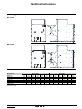
Cradle types
M1 cradle
M2 cradle
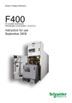
Dimensions
M1 cradles
M2 cradles
1250 A 1250 A 2500 A 2500 A 3000 A 3000 A 1250 A 1250 A 2500 A 2500 A 3000 A 3000 A
Width (cm)
Height (cm)
118
183.5
127
183.5
118
183.5
127
183.5
118
183.5
127
183.5
118
183.5
127
183.5
118
183.5
127
183.5
118
183.5
127
183.5
Depth (cm)
Weight (kg)
219
770
219
978
219
844
219
1052
219
864
219
1072
219
770
219
978
219
844
219
1052
219
864
219
1072
Packing type
the weight of cubicles includes the
circuit-breaker weight
2a
4c
2a
4c
2a
4c
2a
4c
2a
4c
2a
4c
Schneider Electric
03403927EN - REV.A0 - 3
Handling Instructions
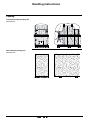
Packing
Overland transport packing (2a)
Functional unit
Sea transport packing (4c)
Functional unit
4 - 03403927EN - REV.A0
Schneider Electric
Handling Instructions
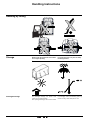
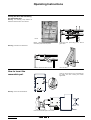
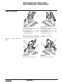
Handling by lifting
Functional unit
Remove the transport hoops.
Sling up the device using the lifting lugs.
Provide 2 m slings as a minimum.
The slings must not form an angle higher
than 60°.
Cubicle gradient must not exceed 10°.
Proceed as shown opposite.
Be careful not to distort the cradle floor
bearing surface.
Handling by rolling
Schneider Electric
03403927EN - REV.A0 - 5
Handling Instructions
Handling by rolling
Storage
Prolonged storage
6 - 03403927EN - REV.A0
When stored, the equipment must remain
in its original packing.
It must be placed on a dry floor or dampinsulating material.
For prolonged storage, the device must
remain in its original packing.
After prolonged storage, care must be taken
to thoroughly clean all insulating parts by
means of a dry, clean cloth prior to use.
Schneider Electric
Handling Instructions
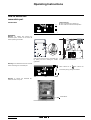
Unpacking the cradles
The cradles must be prepared in the room
where they are going to be fitted.
Equipment
identification
After unpacking, check that the features and
descriptions marked on the cradle rating
plates meet the requirement given in the
contractual documents.
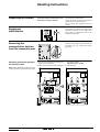
Removing the
transportation devices
from the removable part
Operating instructions relating to
the standard cradle
Avoid impacts and deformation.
Unpack the cradle by removing the wooden
uprights and then the plastic cover.
Do not remove any component from the
cradles.
Open the access door to the removable part
by pulling and then rotating the handle
rightwards.
1: Remove the 2 transport reinforcements (3
screws per reinforcement).
2: Fit the 4 mounting screws of the front plate
and contact washers.
Tightening torque: 8.5 Nm.
3: Flap locking kit.
Note: before sending the cradle back, fit the
2 reinforcements and their screws and bolts.
Schneider Electric
03403927EN - REV.A0 - 7
Handling Instructions
Operating instructions relating to
the internal arc withstand cradle:
1: Remove the 2 transport reinforcements (3
screws per reinforcement).
2: Fit the 4 screws used to fasten the front
plate and contact washers contained in the
bag of screws and bolts.
Tightening torque: 8.5 Nm.
3: Flap locking kit.
Note: before sending the cradle back, fit the
2 reinforcements and their screws and bolts.
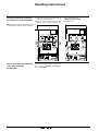
How to extract the removable part
(front plate with black
background)
8 - 03403927EN - REV.A0
To extract the removable part and close the
door, refer to "Operating Instructions",
section "Operation".
Schneider Electric
General description
Glossary
Abbreviations
CT:
Current Transformer or current sensor
LV:
Low Voltage
MALT: Mise A La Terre (earthing)
MV: voltage class from 25 to 36 kV
NVC: No-Voltage Check
SF:
range of SF6 circuit-breakers used in
the F400 cradle
SMALT:Sectionneur de Mise A La Terre
(earthing isolator)
VT:
Voltage Transformer
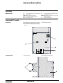
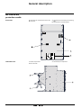
Front side
A: removable part compartment access door
B: removable part position check view ports
C: removable part interlocking and operating
plate
D: removable part blocking
Left-hand view
1: MV connection
2: removable part compartment
Standard M1 cradle
Schneider Electric
03403927EN - REV.A0 - 9
General description
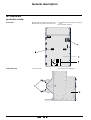
M1 internal arc
protection cradle
Front side
A: removable part compartment access door
B: removable part position check view ports
C: removable part interlocking and operating
plate
D: removable part blocking
Left-hand view
1: MV connection
2: removable part compartment
10 - 03403927EN - REV.A0
Schneider Electric
General description
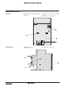
Standard M2 cradle
Front side
A: removable part compartment access door
B: view ports
C: removable part interlocking and operating
plate
D: removable part interlocking plate
Left-hand view
1: busbar compartment
2: MV connection
3: removable part compartment
Schneider Electric
03403927EN - REV.A0 - 11
General description
M2 internal arc
protection cradle
Front side
A: removable part compartment access door
B: view ports
C: removable part interlocking and operating
plate
D: removable part interlocking plate
Left-hand view
1: busbar compartment
2: MV connection
3: removable part compartment
12 - 03403927EN - REV.A0
Schneider Electric
General description
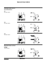
Standard draw-out SF
circuit-breakers
SF1
CEI 1250 A standard
SF2
CEI 1250 A standard
SF2
CEI 2500 A standard
Standard draw-out bar
bridge
1250 A and 2500 A
Schneider Electric
03403927EN - REV.A0 - 13
General description
Internal arc draw-out SF
circuit-breakers
SF1
CEI 1250 A standard
SF2
CEI 1250 A standard
SF2
CEI 2500 A standard
Internal arc draw-out
bar bridge
1250 A or 2500 A
14 - 03403927EN - REV.A0
Schneider Electric
General description
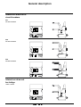
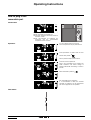
Identification
Functional unit
SF draw-out removable part
A: nameplate
B: features, descriptions and serial number
C: features, descriptions and serial number
1: mechanical opening push-button
2: removable part position selector
3: removable part operating crank insertion
aperture
A: removable part mechanical position
indicator
B: slot for the disconnecting truck lock
(optional)
How to read the
information on the front
side
Removable part
Plug-in disabling
Schneider Electric
A: locking pull for plug-in disabling (plug-in
disabling selector)
B: slot for the plug-in disabling lock
03403927EN - REV.A0 - 15
General description
Symbols
Cradle
"Plug-in disabling" position
"Padlockable" position
Removable part
"Operating" position
"Drawn-out" position
"Plugged-in" position
"Insertion/extraction" position
16 - 03403927EN - REV.A0
Schneider Electric
Layout instructions
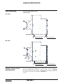
Floor mounting
This step will help to define your civil
engineering basis.
M1 cradle
floor support point
floor fastening point
floor support point
floor fastening point
M2 cradle
Plug-in check on the
operating site
Schneider Electric
Whenever a cradle has been fastened to the
floor, use the circuit-breaker to check that
plug-in and interlocking as well the opening
and closing of the flaps are performed
correctly.
To insert and plug in the removable part and
close the door, refer to "Operating
Instructions", section "How to insert the
removable part".
03403927EN - REV.A0 - 17
Layout instructions
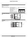
Electrical connections
Screws, bolts and tightening
torque
Note: all the necessary screws and bolts are
supplied, except for the MV cable connection.
Screws and bolts to be used
Bolt joint for MV and LV indoor equipment.
Class 8.8 as per Standard ISO 225, i.e. yield
strength, Re u 627 Nm/mm2
The screws and bolts must not be lubricated.
Tightening torque
Connections must be tightened
by means of a torque wrench, complying with
the following torques:
Application method
The force of the bolts tightened to the
recommended torques is better distributed
thanks to the use of spring washers located
on the outer surfaces of the terminal pads and
busbars.
If disassembly is performed, replace spring
washers.
screw
ø6
ø8
ø 10
ø 12
ø 14
torque in Nm
13
28
50
75
120
Connection of the earth
bar
L1
Front side
L2
225
L3
Earthing connection
point
1127
Insulation
Insulation shields
to be installed
250
1090
300
300
Warning: dielectric insulation shields are not
supplied
Top view
L3
Front side
L2
L
Insulation shields
to be installed
18 - 03403927EN - REV.A0
Schneider Electric
Layout instructions
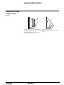
Connection of Low
Voltage cables
S: trough
T: aperture
Through the bottom of the removable part
compartment of each cradle, with trough S
and aperture T communicating with the duct.
Max. quantity of cables: 8
Schneider Electric
Multicore cable ø 20 mm
To have access to aperture T, remove trough
S cover.
03403927EN - REV.A0 - 19
Operating Instructions
How to extract the
removable part
Initial status
Removable part
b The removable part is drawn out.
b The cradle is in disconnected position.
Operation
Warning: for cradles with internal arc
withstand option, loosen the 6 screws A
before operating the handle
Open the access door to the removable part
by pulling and then rotating the handle
rightwards.
Unplug the LV auxiliary connection cord. Clip
the cable on the circuit-breaker.
Warning: the threshold bar must be removed
before extracting the removable part.
Move selector 2 to
then extract the
removable part by pulling the handles.
Warning: to remove the threshold bar,
loosen the nuts on top of it.
threshold bar
Pull out the removable part.
Schneider Electric
03403927EN - REV.A0 - 20
Operating Instructions
Closing the door after extracting
the removable part
Warning: the following steps MUST be
followed to allow the door to be closed.
Panel
Before closing the access door to the
removable part, lower the panel.
Inside the door, pull locking part 1. Rod 2
goes down.
The door closes but does not lock.
Close the door.
Warning: put back the threshold bar.
How to insert the
removable part
Open the access door to the removable part
by pulling and then rotating the handle
rightwards.
Warning: remove the threshold bar.
Insert the removable part in the cradle.
Schneider Electric
03403927EN - REV.A0 - 21
Operating Instructions
Move selector 2 to
.
Push the removable part into the cubicle until
its is in abutment then move selector 2 back
to position
.
Connect the LV auxiliary connection cord.
Putting back the threshold bar
Insert the threshold bar A tilting it slightly,
align slots B with threaded rods C, then fit the
threshold bar.
Loosen nuts D.
E: Before closing the access door to the
removable part, lift the panel and check that it
is properly latched at the top.
F: Lift rod 2, topple locking part 1 over and
release rod 2.
The door closes but does not lock.
Close the door.
Closing the door with the
removable part in place
Warning: if closing is impossible, check the
following points given in E and F.
22 - 03403927EN - REV.A0
Schneider Electric
Operating Instructions
How to plug in the
removable part
Initial status
Removable part
b The removable part is drawn out.
b Operation should be allowed by means of
the locks, if fitted.
b The circuit-breaker LV auxiliaries are
connected
and
the
circuit-breaker
compartment door is closed.
Operation
If it is key-locked: insert the key in H.
Lower the protection flap of push-button 1.
Press push-button 1. Hold it down to move
selector 2 to position
.
Lift the protection flap of push-button 1.
Insert the crank in aperture 3.
Plug in the removable part by rotating the
crank clockwise until status change of
position indicator A and locking of crank in
rotation.
Move selector 2 to position
.
The removable part is plugged-in.
If a circuit-breaker is used, the electrical
operation for switching on the downstream
part of the equipment is now possible.
Final status
Schneider Electric
03403927EN - REV.A0 - 23
Operating Instructions
How to draw-out the
removable part
Initial status
Removable part
b removable part in plugged-in position.
Operation
If it is key-locked: insert the key in H.
Lower the protection flap V of push-button 1.
Press push-button 1 (which triggers a circuitbreaker mechanical opening order).
Hold it down to move
selector 2 to position
.
Lift protection flap V of push-button 1.
Insert the crank in aperture 3.
Draw out the removable part by rotating the
crank counter-clockwise until status change
of position indicator A.
Move selector 2 to position
.
The removable part is drawn out.
The cubicle is in disconnected position.
Final status
24 - 03403927EN - REV.A0
Schneider Electric
Operating Instructions
Padlocking
Padlock with ø 6 to 8 mm can be used
b on the plug-in disabling selector,
b on the protection flap of the removable part
mechanical opening push-button,
b on the flap opening mechanisms inside the
removable part compartment,
Disabling the removable part
plug-in
Fit 1 to 3 padlocks on plug-in disabling
selector (D) in the following position
Disabling the mechanical
opening order of a circuit-breaker
in operation position
This device can also be used as an
additional plug-in and draw-out disabling
system.
Opening the flaps
Refer to "Maintenance Instructions",
section "Access to upper and lower plug-in
blocks".
Operating the adjustable VT
Refer to "Adjustable voltage transformer",
section "How to operate the adjustable
voltage transformers".
Schneider Electric
b on the adjustable voltage transformer
operating mechanism.
Fit a padlock on the protection flap of
mechanical opening push-button 1.
03403927EN - REV.A0 - 25
Testing
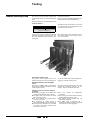
Switchboard dielectric
test
This test can be performed in a single
operation.
All circuit-breakers must be plugged-in and
closed, with the cradle doors open.
Furthermore, one of the outgoing cradles
must have its MV cable compartment open
for the connection of the test cable.
55 mm
wedge
This preparation requires the manual
disabling of interlocking to plug in the circuitbreakers, with the door open.
The sequence below must absolutely be
followed.
Position the circuit-breaker in drawn-out
position, with the door open.
Lift and lock the door locking rod by means of
a 55 mm high U-shaped wedge.
Plug in the circuit-breaker.
Remove the wedge.
The manual closing of the circuit-breaker by
pressing button "I" is then possible by means
of its mechanical control.
A
Schneider Electric
Indicator A indicates the status of the circuitbreaker ("O" or "I").
The test can be performed.
03403927EN - REV.A0 - 26
Testing
Testing the current
transformers
Warning: the connection accessory must not
damage the fixed block coating.
Injection at primaries
An injection at the current transformer
primaries is possible by access to the fixed
plug-in blocks located in the circuit-breaker
compartment.
Injection at secondaries
The tests and settings will be preferably
performed by injection at secondaries, using
the test and injection boxes provided in the
LV compartment.
1: Extract the removable part.
2: Close the earthing isolator
3: Padlock the opening of the lower flap
providing access to the fixed blocks on the
busbar side.
4: Access the fixed blocks on the current
transformer side through the upper flap
opening.
Changing the winding ratios at the
secondary.
Any change in the winding ratio is performed
by access to a specific terminal board inside
the low voltage compartment (see LV
developed diagrams).
After testing
1: Remove the injection device.
2: Close the upper flap.
3: Remove the padlock blocking the opening
of the lower flap.
Schneider Electric
5: Fit the injection device between the fixed
block (primary terminal P1) and the cubicle
earth bar which can be accessed in the
circuit-breaker compartment. Terminal P2
of the transformer is connected to the
cubicle earth bars by means of the
earthing isolator in closed position.
This operation is performed with the
transformer primaries de-energized and
earthed by closing of the earthing isolator.
4: Open the earthing isolator
5: Insert the removable part.
03403927EN - REV.A0 - 27
Testing
Busbar earthing truck
The earthing of the Fluair 400 cradle busbar
is provided by means of a circuit-breaker-type
truck.
All circuit-breakers in the switchboard can be
extracted if necessary.
Busbar earthing truck F400 complies with the
requirements of standard NFEN 60129.
Technical features
Rated voltage = 36kV
Ith = i.e.
25kA - 3s
Ith = i.e.
31,5kA - 3s
"Power on" device: no
A double lock can be provided with separate
operating mechanisms releasing cams that
abut the polarization block located on the
cradle floor.
Each double lock is then allocated to one of
the ½ sets of cubicles (L-H or R-H) by means
of a central key box.
Polarization of MALT trucks
The purpose of this optional device is to
impose the draw-out of all circuit-breakers in
a ½ set of cubicles and of the coupling before
plugging in a busbar earthing truck
Recommendations for operating MALT
trucks
The plug-in of a MALT truck is performed by
means of the propulsion mechanism used for
circuit-breakers (crank).
The closing-opening operations of the main
contacts are performed manually by the
operator, with the cubicle MV door open.
The MALT truck is used in the following
conditions:
b possibility of plugging in the MALT truck
with the cradle MV door open or closed
b the MALT truck only operates the lower
flap of the plug-in bells
b the truck operates the plug-in/draw-out
contacts of the cradle
b the positioning of closing springs is
performed manually by means of the lever
b opening-closing operations are controlled
by means of the buttons located on the
front panel of the truck
28 - 03403927EN - REV.A0
The MALT trucks are planned to be inserted
in a 1250A cradle on the switchboard for the
main earthing of the busbar.
b the "O-C" buttons are padlockable
separately
b the truck can be inserted with the earthing
isolator (SMALT) closed or open
b the SMALT remains operable with the
MALT truck plugged-in
b the MALT truck is equipped with a
separation prohibiting access to energized
parts when the truck is plugged-in
Schneider Electric
Testing
Once plugged in, the MALT truck is
considered as potentially closed.
As a result, it does not have the following
auxiliaries:
b auxiliary contacts indicating the status of
the MV main contacts
b electric control systems to ensure the
remote opening-closing controls
The "O-C" position mechanical indicator
of HV contacts is:
b black for OPEN
b white for CLOSED
Schneider Electric
03403927EN - REV.A0 - 29
Maintenance Instructions
Ordering parts
When preparing the order, refer to this
manual supplied with the system to define
the equipment desired very precisely.
To order any equipment, you must
indicate:
b type of cradle,
b manufacturing number (engraved on the
identification plate located on the left-hand
panel of the removable part compartment).
b If possible, attach a diagram of this manual
on which the part is conspicuous.
Before performing any task, make sure of
the strict compliance with operating and
safety instructions.
Our equipment is designed to guarantee
optimum operation provided that the
maintenance instructions described in this
manual are strictly adhered to.
Start each maintenance task with the
thorough cleaning of the cradle.
The use of pressurized solvent projection
as a cleaning process is prohibited.
Warning:
Schneider
Electric
cannot
guarantee the durability and reliability of the
equipment subjected to this type of cleaning
process, even if followed with lubrication.
The main risks related to this process are
as follows:
b de-lubrication of sliding rails and joints (life
lubricated),
b corrosion of unprotected parts,
b damage and deformation due to high
pressure,
b overheating due to solvent on contact
areas,
b elimination of special protections.
Preventive
maintenance
Maintenance points
Removable part
Warning: should clamps be damaged, the
corresponding MV fixed block in the cradle
shall be inspected.
Warning: prior to any application, remove the
old grease.
Removable part compartment
Warning: for electric contacts, do not use
grease of "Kluber Isoflex Topas L152" type or
equivalent.
Extract the removable part (refer to
section "How to extract the removable
part").
Referring to its user's manual, perform an
overall check of the system.
b Clean insulating parts.
b Apply a thin film of grease, "Kluber
Amblygon TA 15/2" type or equivalent, to
the plug-in clamps.
Extract the removable part.
Check and lubricate:
b pins and joints, mechanisms and sliding
rails of flaps ("Kluber Isoflex Topas L152"
or equivalent),
b the earthing plate ("Kluber Amblygon TA
15/2" or equivalent),
b behaviour at the LV wiring connection
points.
Warning: prior to any application, remove the
old grease. Remove dust and clean the inside
of the compartment and the plug-in insulating
parts.
Schneider Electric
03403927EN - REV.A0 - 30
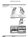
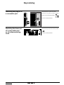
Maintenance Instructions
Access to upper and
lower plug-in blocks
Opening the flaps
Left-hand side
A: lower flap latch finger.
Right-hand side
B: upper flap latch finger.
The plug-in blocks are accessed by manual
opening of the lower flap:
b on the busbar side, in an incoming/
outcoming cubicle,
b on the left-hand busbar side, in a circuitbreaker coupling cubicle.
The plug-in blocks are accessed by manual
opening of the bottom flap:
b on the MV cable side, in an incoming/
outgoing cubicle,
b on the right-hand busbar side, in a circuitbreaker coupling cubicle.
Left-hand side
Padlock the opening of the upper flap (refer to
section "Flap interlocking").
Left-hand side
Using a screwdriver, release latch finger A.
Push to open the flap.
Schneider Electric
After maintenance, close the flap by lifting it
manually until it locks, then remove the
padlock locking the upper flap.
03403927EN - REV.A0 - 31
Maintenance Instructions
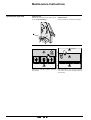
Operating the upper flap
Right-hand side
Padlock the opening of the lower flap (refer to
section "Flap interlocking").
Holding latch finger B, in position, push the
flap upwards.
32 - 03403927EN - REV.A0
Right-hand side
Using a screwdriver, release latch finger B.
After maintenance, lower the flap manually
until it locks, then remove the padlock locking
the lower flap.
Schneider Electric
Maintenance Instructions
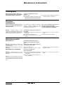
Trouble-shooting
Symptoms
Faulty devices
Possible causes and solutions
Abnormal noise with power on
(crackling, vibrations)
b insulators
Damp or dirty
b clean or dry them
Incorrectly fastened
b check fasteners
Incorrect cubicle connection
b check the connections
Connections incorrectly tightened
b retighten them, see tightening torque, contact surfaces ill adapted
or damaged
b change or clean them
Anomaly resulting from deformation
b adjust
Abrupt handling, MV network overvoltage
b change the "power on" block
Faulty
b check it (see wiring diagram)
Capacitor damaged
b change the unit
Insulator capacitor damaged
b change insulator
Operation incomplete
b refer to the removable part extraction chapter
Action of a protection
b check the relay settings and remove the fault
Faulty
b check it by successive eliminations
Faults on LV circuit
b trouble-shooting by successive eliminations
In "Out of operation" position
b close it
b metal components
Excessive overheating at connection points
b upstream or downstream
connection
b connection
Operation requiring abnormal effort
One of the "power on" Leds does not come
on
b Led
b wiring
b "power on" Led functional unit
b capacitor insulator
Circuit-breaker does not close
b protection relay
b wiring
b LV circuit-breaker
b section switch
Schneider Electric
03403927EN - REV.A0 - 33
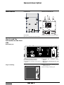
Low Voltage compartment
Mounting instructions
Connecting the LV
cables
Refer to the plan provided with the LV
compartment kit
P:
Q:
R:
plate
terminal block
terminal block
S:
T:
trough
aperture
Access to connection terminal
blocks
LV terminal blocks are located at the top of
the LV compartment.
Loosen fastening screws and remove roof P.
Q: connection terminal block
R: auxiliary supply earth bar terminal block
The Low Voltage wiring can enter the
cradle in 2 different ways depending on
the equipment.
1: Through the rear of the LV compartment.
2: Through the bottom of the circuit-breaker
compartment of each cradle, with trough S
and aperture T communicating with the
duct.
Schneider Electric
Max. quantity of cables: 8
Multicore cable ø 20 mm
To have access to aperture T, remove trough
S cover.
03403927EN - REV.A0 - 34
Adjustable voltage transformer
Mounting instructions
Refer to the plan provided with the VT
compartment kit
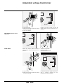
How to operate the
adjustable voltage
transformers
Voltage transformers can be in the position "in
operation" (primary fuses and transformers
connected to MV cables or switchboard
busbars) or "out of operation" (primary fuses
and voltage transformers disconnected).
"Out of operation" position
A: operating handle in the top position
B: latch
C: fuse ends visible
D: fuse extraction slot
"In operation" position
A: operating handle in the bottom position
B: latch
D: fuse extraction slot
E: fuse slot retractable closing flap in closed
position
Handle A in top position, flap E open and fuse
ends C apparent, indicate that the
transformers are out of operation.
1: Push the latch to the left.
2: Pull the handle.
How to put the VTs in operation
Initial status
Schneider Electric
03403927EN - REV.A0 - 35
Adjustable voltage transformer
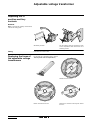
3: Lower the handle.
4: Block the assembly in position by pushing
the latch to the right.
5: Lock with a padlock
Handle A in bottom position and flap E
closed, indicate that the transformers are in
operation.
Handle A in bottom position and flap E
closed, indicate that the transformers are in
operation.
1: Remove the padlock.
2: Pull the handle.
3: Push the latch to the left.
4: Lift the handle.
5: Block the assembly in position by pushing
the latch to the right.
Handle A in top position, flap E open and fuse
ends C apparent, indicate that the
transformers are out of operation.
How to put the VTs out of
operation
Initial status
36 - 03403927EN - REV.A0
Schneider Electric
Adjustable voltage transformer
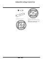
Replacing the VT
position auxiliary
contacts
Removal
Note: to access the auxiliary contact block,
remove the closing plate.
A: auxiliary contacts
Fitting
Replacing the fuses of
the adjustable voltage
transformers
For the auxiliary contacts, separate the crank
on the compartment side and remove the 4
mounting screws.
Proceed in the reverse order.
Put the VTs out of operation (refer to section
"How to put the VTs out of operation").
Release the two screws.
Rotate and remove the fuse.
Schneider Electric
Remove the fasteners and bayonet A from
the fuse...
03403927EN - REV.A0 - 37
Adjustable voltage transformer
... and fit them on the new fuse.
Fully insert the fuse and rotate.
Lock the two screws to the recommended
torque.
Put the VTs out of operation (refer to section
"How to put the VTs in operation").
38 - 03403927EN - REV.A0
Schneider Electric
Interlocking the flap on the
removable part compartment
Flap interlocking
Left-hand side
The plug-in blocks are accessed by manual
opening of the lower flap:
b on the busbar side, in an incoming/
outcoming cubicle,
b on the left-hand busbar side, in a circuitbreaker coupling cubicle.
Right-hand side
The plug-in blocks are accessed by manual
opening of the upper flap:
b on the MV cable side, in an incoming/
outgoing cubicle,
b on the right-hand busbar side, in a circuitbreaker coupling cubicle.
After the removable part has been extracted
from the cubicle, the upper or lower flap can
be locked by means of 1-2 or 3 padlocks.
1: Position the part (K and L),
2: padlock.
Note: the 2 operating mechanisms are
separate.
L
Left-hand side
F: padlocking
G: lower flap operating mechanism
Schneider Electric
Right-hand side
H: padlocking
J: upper flap operating mechanism.
03403927EN - REV.A0 - 39
Key-locking
Disabling the plug-in of
a removable part
Removable part in drawn-out position.
Remove the key when the plug-in disabling
selector is in the following position:
Draw-out is then impossible.
Disabling the draw-out
of a removable part
or of a disconnecting
truck
Schneider Electric
Remove the key when selector 2 is in position
.
Draw-out is then impossible.
03403927EN - REV.A0 - 40
"Power on" device
Testing "Power on"
As soon as the cables have been energized,
the "power on" indicator Leds L1, L2 and L3
must come on.
Checking phase
coincidence between
two cradles
Phase coincidence:
the tester lamp does not come on.
Phase unbalance:
the tester lamp comes on.
Check that power is off.
The "power on" indicator Leds are off.
It is recommended to lock the tester in this
position.
Replacing the "power
on" Led block
Removal
Mark and disconnect the wiring connector.
Remove the fasteners and free the "power
on" Led block.
L1
L2
L3
Fitting
A
Set the "power on" block according to the
arrow direction (see above) and plug the
Schneider Electric
connector in the rear side.
Tighten the 2 screws to a 0.1m daN torque.
03403927EN - REV.A0 - 41
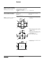
Busbar
Mounting the busbars
Warning: the bars and all the contact
surfaces must be clean on mounting.
Intermediate busbars
The kit is supplied in a separate parcel
including the following parts:
v busbars,
v connectors and associated screws and
bolts,
A: connector half
B: bushing
C: bare or insulated bars
Warning: the sequence of operations and
tightenings MUST be complied with.
v insulating covers.
D: hex socket screw ø 14 + washer
E: cover half
1: Assemble the bars and connectors and fit
the fasteners
B
A
C
C
2: Bring up the screws and nuts to the limit
stop in the order shown below, but do not
lock them in position:
1-2-3-4-5
3: Using a torque wrench, tighten the screws
in the order recommended above in 2
successive runs:
b 1st run to a 25 Nm torque,
b 2ndrun to a final torque of 75 Nm.
4: Assemble the 2 cover halves E by exerting
pressure on clips.
clips
Schneider Electric
03403927EN - REV.A0 - 42
Busbar
End busbars
E: hex socket screw ø 14 + washer
F: cover
G: binding
A: connector half
B: bushing
C: bare or insulated bars
D: screwed-on sleeve
Warning: the sequence of operations and
tightenings MUST be complied with.
Note: in this case, a sleeve D is screwed onto
a connector half.
1: Assemble the bars and connectors and fit
the fasteners
End
2: Bring up the screws and nuts to the limit
stop in the order shown below, but do not
lock them in position:
1-2-3-4-5
3: Using a torque wrench, tighten the screws
in the order recommended above in 2
successive runs:
b 1st run to a 25 Nm torque,
b 2ndrun to a final torque of 75 Nm.
4: Fit the insulating cover
F on the
connector. Lock it in position by means of
2 plastic bindings G.
G
G
Do not cut out.
Maintaining the busbar
compartment
Schneider Electric
Remove dust and clean the inside of the
compartment and the insulators
Tightening torque
The connections must be tightened by means
of a torque wrench, complying with the
following torques:
screw
ø6
ø8
ø 10
ø 12
ø 14
torque in Nm
13
28
50
75
120
03403927EN - REV.A0 - 43
44 - 03403927EN - REV.A0
Schneider Electric
Schneider Group service centers are available for:
engineering and technical assistance
start-up
training
preventive and corrective maintenance
adaptation work
spare parts
03403927EN - REV.A0 - © 2002 Schneider Electric - All rights reserved
Call your sales representative who will put you
in touch with your nearest Schneider Group Service Center,
or call directly Grenoble France on 33 (0)4 76 57 60 60
Schneider Electric Industries SA
F-38050 Grenoble cedex 9
Tel. : +33 (0) 4 76 57 60 60
Fax : +33 (0) 1 47 51 80 20
As a result of the development of specifications and designs, always ask for confirmation of
the information given in this publication.
http:/www.schneiderelectric.com
RCS: Nanterre B 954 503 439
Publication: Schneider Electric
Layout: Cabinet MARTINEZ SARL - NANTES
Printed by: Cabinet MARTINEZ SARL - NANTES
03403927EN - REV.A0
This document has been printed on co-friendly paper.
12/03