1
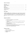
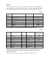
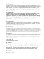
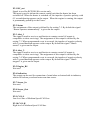
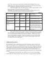
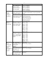
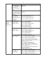
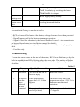
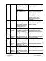
RCP Can FTC
Version 7.2
Technical description
User manual
Rev. A
2
Table of Contents
Description ……………………………………………………………………
2
Module Possibilities .…………………………………………………………..
2
Package Content ……………………………………………………………….
2
Signals ……………..…………………………………………………………..
3
Connection ……………………………………………………………………..
6
Basic Functions ………………………………………………………………...
6
Additional Functions ………….……………………………………………….. 7
Troubleshooting …………………………………………………………….…. 12
Glossary ……………………………………………………………………….. 14
Description
The RCP Can-FM module is intended for remote control connection to the fuelfired heater (parking heater, fuel operated heater, pre-heater), which was factory
equipped on Ford Transit Custom (2013-) and Ford Tourneo Сustom (2013-),
including the original Ford vehicle key. The device controls the heater via CANbus.
Module Possibilities
· The heater start and stop by various impulses
· Heater status signals
· Embedded remote control of the heater by the original 3-button Ford
vehicle key
· Remote cancellation of the heater start, programmed by the driver
information system
· Extended boost heat mode control
· Main battery protection from discharging by inspection of the voltage
level and time of autonomous work of the heater
· Heater errors clearing (unblocking)
Package Content
1.
2.
3.
4.
RCP Can-FM module
Wiring for permanent connection
Plug-n-play cable
Manuals
3
Signals
The module has two connectors: 9-pin connector X1 (table 1) for input signals and
power connection, 10-pin connector X2 (table 2) for output signals, special signals
and CAN-bus connection. The first pin on each connector is marked by the key.
Table 1
X1 pin
Signal Name
Polarity
Wire colour
number
1
Heater_off+
+
White
2
Heater_offGrey
3
Heater_on+
+
Green
4
Heater_onBlue
5
Button
Brown
6
Timer _in
+
Orange
7
RC_in
+
Yellow
8
Ground
Black
9
Battery Power
Red
The signals to be necessarily connected marked in the table by Italics
Table 2
X2 pin Signal Name
number
1
2
3
4
5
6
7
8
9
10
RC_out
Heater_Status
Alert_1
Alert_2
Engine_RS
Indication
Sensor_In
Sensor_Out
CAN-L
CAN-H
Polarity Wire colour
+
+
-
Blue-white
Yellow
Grey
Orange
Blue
Red-white
Green-yellow
Green
Brown-white
Brown
Maximum
Electric Load*,
mА
500
500
500
500
500
1000
500
*The connection of outputs 2-5 directly to the Power, without a load, is not
permitted. The connection of outputs 1 and 6 directly to the Ground, without a
load, is not permitted
The signals to be necessarily connected marked in the table by Italics
4
X1.1 Heater_off+
The input can be used to switch off the heater, operated in pre-heat mode, by the
impulse of positive polarity (the input Heater_off- in that case has to be connected
to the Ground). The heater is stopped by the leading edge of the impulse. If the
heater is idle, positive impulse on this input cancels the program start of the heater,
programmed by DIS.
X1.2 Heater_offThe input can be used to switch off the heater, operated in pre-heat mode, by the
impulse of negative polarity (the input Heater_off+ in that case has to be
connected to the Power). The heater is stopped by the leading edge of the impulse.
If the heater is idle, negative impulse on this input cancels the program start of the
heater, programmed by DIS. This input is suitable for the most alarm systems and
GSM-modules connections in order to control the heater remotely.
X1.3 Heater_on+
The input can be used to switch the heater on by the impulse of positive polarity
(the input Heater_on- in that case has to be connected to the Ground). The heater
is started by the leading edge of the impulse.
X1.4 Heater_onThe input can be used to switch the heater on by the impulse of negative polarity
(the input Heater_on+ in that case has to be connected to the Power). The heater is
started by the leading edge of the impulse. This input is suitable for the most alarm
systems and GSM-modules connections in order to control the heater remotely.
X1.5 Button
The input for outer multi-functional button connection. The current function of the
button depends on the heater status, the ignition status and the engine status (see
Table 4 for more details)
X1.6 Timer_in
Not used in current version
X1.7 RC_in
The input can be used to switch the heater on/off by an impulse of positive
polarity. The heater is turned on by the leading edge of an impulse and is turned off
by the trailing edge of the impulse. The specialized remotes such as Smart Start,
Easy Start and Telestart can be connected to this input. GSM-modules with a
potential signal on the control channel also may be connected to the input.
X1.8 Ground
X1.9 Power +12V
5
X2.1 RC_out
Signal is used for RCP DSS Kit version only
The input is used to inform the remote control unit that the heater has been
switched off. When the heater is switched off, the impulse of positive polarity with
0.5 second duration appears on the output. When the engine is running, the output
is permanently pulled up to the Power.
X2.2 Status
The assignment of this output is defined by the setting 7.5. By default the signal
“Heater operates autonomously” is given on the output.
X2.3 Alert_1
The signal is used to receive a notification to remote control (if remote is
compatible to alerts receiving). The assignment of this output is defined by the
setting 7.3. When programmed event is occurred, the impulse of negative polarity
with 1 second duration appears on the output. By default the signal “Heater
started” is given on the output.
X2.4 Alert_2
The signal is used to receive a notification to remote control (if remote is
compatible to alerts receiving). The assignment of this output is defined by the
setting 7.4. When programmed event is occurred, the impulse of negative polarity
with 1 second duration appears on the output. By default the signal “Heater
stopped” is given on the output.
X2.5 Engine_RS
Not used
X2.6 Indication
The output can be used for connection of stand alone or button built-in indicator,
which will inform you about heater run-time errors.
X2.7 Sensor_In
Not used
X2.8 Sensor_Out
Not used
X2.9 CAN-L
Low-level line of Medium Speed CAN bus.
X2.10 CAN-H
High-level of Medium Speed CAN bus.
6
Connection
RCP Can has two variants of connection. Plug-n-play connection is easy type of
connection which not requires special skills. Permanent connection is
recommended for professional installation. It needs at least some experience in car
electronics installation. Read installation manual for detailed connection schemes.
Basic Functions
1. To start/stop the heater by additional remote control, see documentation for
the remote control. The functions of the remote control depend on its
possibilities, connection schemes and module’s settings.
2. To start the heater by the original Ford key press “Unlock” button 3 times
and then press “Lock” button. Time intervals between presses must not
exceed 20 seconds. The excess of time interval will restart the counter of
“Unlock” button presses. Watch to the turn signals to be sure that RCP has
received a command from the key: every “Unlock” button press on the key
will be confirmed with long single flash of hazard flashers, “Lock” button
press on the key will be confirmed with short double flashes of hazard
flashers.
3. The RCP Can is adjusted by default only to switch the heater on by Ford
key. If you also plan to switch off the heater too, change the setting 3.1. As
both the commands use the same combination of “Unlock” presses, you
should know a condition of the heater before a command send. The
possibility to stop the heater remotely may be useful in the case of
cancelation of the trip, including ones programmed by DIS.
4. You can remotely cancel the start of the heater by a DIS program, if your
additional remote control can send stop command when the heater is idle
(not possible by Ford key). After stop command sending, DIS programs will
be temporary disabled. Starting the heater by any way or turning the
ignition on will enable DIS programs again.
5. Additionally installed button has several functions. Current function is
defined by the heater condition, the ignition condition and the engine
condition (see table. 3)
When the ignition is turned off, the button is used for immediate start or
stop of the heater. Button press changes a heater condition to another one:
switches off the operated heater or switches on the idle heater.
When the ignition is turned on, button press keeps the current condition
of the heater after the engine start. So, if the heater has operated before the
engine start, it may continue to operate after the engine start (in boost heat
mode). If the heater has been idle before the engine start, button press will
inform RCP don’t let the heater to start in boost heat mode after the engine
7
start. These functions are called quick enabling and disabling of boost heat
mode respectively. Being activated these functions act for the current ignition
cycle. Turning the ignition off cancels function activity.
When the engine runs, the button press is used to quick enable of the
boost heat mode (if boost heat mode was disabled).
Warning! The parking heater must not be operated at filling stations, near
sources of combustible vapours or dust or in enclosed spaces
Table 3
Button function
Ignition Engine
Heater Description
status
status
status
(how to use)
Heater immediate Off
Not running Off
One-touch heater start
start
Heater immediate Off
Not running On
One-touch heater stop
stop
One-time boost
On
Not running Off
Quick disabling of boost
disable
heat mode for short trips
One-time boost
On
Not running On
Quick enabling of boost
enable
heat mode in the case of
boost heat mode disabling
by RCP settings or in the
On
Running
Off
case of one-time disabling
previously
The fuel fired heater needs about 3 minutes to go to the normal operation
after the startup. If your trip is planned to be shorter, it is highly recommended
to use a button function called “one-time boost disable”. This preserves the
heater from premature clogging. Turn on the ignition, press the button, then
start the engine. Now the heater will not operate with the engine while don’t
you enable boost heat mode again.
Additional Functions
By default RCP Can is adjusted to execute basic functions, such as a start of the
heater by the Ford key or by additional button, a stop of the heater by the button
and a control of the boost heat mode by the button. To turn on additional functions
(a possibility to stop the heater by Ford key, battery monitoring, indication by the
turn signals in the rear-view mirrors, extended control of boost heat mode, etc.)
you may enter the module into programming mode and activate the corresponding
setting.
Programming button and the brake pedal are used to enter programming
mode and to the settings change. Plug-n-play cable is equipped with preinstalled
8
programming button. Use additionally installed button as programming button in
the case of permanent connection of the module.
It is necessary to stop the engine and the heater before. Turn the ignition on,
press and hold the brake pedal. Then press and release 3 times programming button
(hold additional button every time until LED is not goes off, about 1.5 seconds).
Both turn signal repeaters in DIS will flash twice (LED goes on) as a confirmation
of entering programming mode. Release the brake pedal now.
Each setting in the table 1 corresponds to the 3-digit code. You need to enter
appropriate code to activate a setting. To enter a digit of a code, press the button so
much times, as corresponds to a digit. Each button press is confirmed by a turn
signal repeater of DIS (the left turn to the first and the third digits of code, the right
turn to the second digit of code) and by a LED blink. To confirm enter of a digit
press and release the brake pedal (DIS flashes one time by the both repeaters
simultaneously). When the third digit is entered, module check the code for
validity and confirm it by repeaters (flash twice by the both repeaters
simultaneously in the case of valid code, flash twice by the both repeaters
alternately in the case of invalid code) and by a LED (goes off once a second twice
in the case of valid code, goes off for 2 seconds in the case of invalid code).
If you made a mistake with the number of button presses when you enter the code,
press and release the brake pedal until the module indicate an error by repeaters.
Enter the code again in that case. Also you may enter other codes without exit of
programming mode.
Release a brake pedal and turn the ignition off to exit programming mode. New
settings will be saved in the module’s memory and will be stored there regardless
of whether the module is connected or not. Attention: If you start the engine
without exit of programming mode, new settings will not be saved in memory.
To reset the module to factory settings, enter the code 8.1.1. Both repeaters will
flash three times to confirm command execution, and then the module will exit of
programming mode and will restart.
To clear all the errors in the heater’s memory and thus unblock the heater, enter the
code 9.1.1. Both repeaters will flash five times to confirm command execution. If
unblocking of the heater is impossible, the repeaters will flash five times
alternatively. Pay attention: when you apply unblocking function for the first
time, RCP Can remember VIN code of the car. In the future unblock function will
work only for this car.
Settings Table (4)
2.
Heater
Timing
2.1. Limitation of
heater’s total
operation time in
pre-heat mode
2.1.1
2.1.2
2.1.3
2.1.4
2.1.5
2.1.6
2.1.7
2.1.8
*Not applied
40 minutes
50 minutes
60 minutes
70 minutes
80 minutes
90 minutes
100 minutes
9
2.1.9 120 minutes
2.2. Limitation of
2.2.1 10 minutes
heater’s cycle
2.2.2 15 minutes
operation time in
2.2.3 20 minutes
pre-heat mode
2.2.4 25 minutes
2.2.5 *30 minutes
3.1. “Unlock”
3.1.1 *Heater start only
3.
Heater
button function for 3.1.2 Start of idle heater, stop of operated
remote
the heater control
heater
control by
3.2. “Unlock”
3.2.1 Heater control by Ford key is disabled
Ford Key
button presses count 3.2.2 Two presses
to start the heater
3.2.3 Three presses
3.2.4 *Four presses
3.2.5 Five presses
3.2.6 Six presses
4.1.1 * Not adjusted
4.
4.1.
Battery
Minimal voltage to 4.1.2 11.4V
Monitoring
let the heater start
4.1.3 11.6V
in pre-heat mode
4.1.4 11.8V
4.1.5 12.0V
4.1.6 12.1V
4.1.7 12.2V
4.1.8 12.3V
4.1.9 12.4V
4.2.1 * Not adjusted
4.2.
Minimal voltage to 4.2.2 10.6V
keep operating the 4.2.3 10.8V
heater for pre-heat
4.2.4 11.0V
2
mode
4.2.5 11.2V
4.2.6 11.4V
4.2.7 11.5V
4.2.8 11.6V
4.2.9 11.7 V
6.1. Indication of
6.1.1 Off
6.
Heater
command reception 6.1.2 *Three flashes
startup and
from remote
operation
control7
mode
6.2. Indication of
6.2.1 Off
indication by successful startup of 6.2.2 *Seven flashes
the turn
the heater via
6
signals
remote control
6.3. Indication of
6.3.1 *Off
the operated heater, 6.3.2 On
started by remote
10
7.
Output
signals
adjustment
control
6.4. Indication of
the operated heater,
started by DIS
(direct or program
start)
6.5. Indication of
the operated heater,
started by additional
button
6.7. Flashing
frequency for
indication of heater
autonomous
operation
7.3. Notification
signals on the
output “Alert_1”
6.4.1 *Off
6.4.2 On
6.5.1 *Off
6.5.2 On
6.7.1
6.7.2
6.7.3
6.7.4
One flash within 3 sec
One flash within 5 sec
* One flash within 10 sec
One flash within 15 sec
7.3.1
7.3.2
7.3.5
7.3.6
7.3.7
7.3.8
*"Heater started"4
"Heater stopped"4
"Heater started to burn"4
“Heating finished
"Error occured"
Disable the output
7.4. Notification
signals on the
output “Alert_2”
7.4.1
7.4.2
7.4.5
7.4.6
7.4.7
7.4.8
"Heater started"4
*"Heater stopped"4
"Heater started to burn"4
“Heating finished
"Error occured"
Disable the output
7.5. Signals on the
output “Status”
7.5.1 Heater operates (potential)
7.5.2 *Heater operates autonomously (from
battery, engine is off) (potential)
7.5.3 Hazard flashers control (double
impulses with the frequency adjusted by 6.7,
applying settings 6.1-6.5)5
7.5.4 Engine runs (potential)
7.5.5 Engine runs (RPM impulses)
7.5.6. Ventilation is on during the heater
operation (potential)
7.5.7. Ventilation is off during the heater
operation (potential)
7.5.10. Disable the output
7.6.1 Heater operates (potential)
7.6.2 *Heater operates autonomously (from
battery, engine is off) (potential)
7.6.3 Feedback for Defa Vehicle Unit
7.6. Signal feed to
the output
“Status_Plus”
11
8.
Settings reset
9.
Heater errors
reset
7.6.4 Engine runs (potential)
7.6.5 Ventilation is on during the heater
operation (potential)
7.6.6. Disable the output
8.1.1 Apply factory settings
9.1.1 Clear all errors in heater’s memory,
resulting heater unblocking
* Factory setting
Recommended settings is marked in italics
2
–RCP will turn off the heater if the battery voltage becomes lower than presetted
– Setting is not tested yet
4
– Signals appear only at the heater autonomous operation
5
– Signal is used for indication by the hazard flashers. It uses 1-wire connection to
the hazard alarm button (see installation manual for details).
6
– Additional connections required (see installation manual), not via plug-n-play
cable
7
– Ford key only
3
Troubleshooting
If a run-time error occurs at the start of the heater, RCP Can will inform you by the
built-in and additional LEDs blinking about the error code. The number of flashes
corresponds to the error code. See table 5 for the codes description and possible
solutions.
Table 5
Error
Error
Possible Reasons of
Solutions
Code Description
Error Appearance
1
Start error
Fuel level in the tank is
Refuel the vehicle
close to empty
2
No answer
from the
heater
followed
the start
command
Outer temperature is
upper than +15 Celsius
degrees
The heater works only with
temperatures below +15°C. It is
the heater manufacturer's
restriction
The engine is hot (no
need to pre-heat)
Let the engine cool down below
+75 degrees
12
The heater hasn’t
finished previous cycle
of operation yet (you can
hear the noise from the
air blower fan)
The heater is blocked
after 5 unsuccessful
starts
3
Battery
level is low
4
Time limits
exceeded
5
Unsuccessful start
Operation
cycle too
short
6
8
CAN-bus
error
9
Settings
error
11
Heater no
connection
© Autoplugin ES
The module has
determined that the
battery voltage at the
heater startup or during
the heater operation is
below the specified
settings 4.1 и 4.2
Time limit for
autonomous operation of
the heater is achieved
(with active setting 2.1.2
- 2.1.9)
The heater switched off
spontaneously at startup
The heater was switched
off spontaneously with
operating time of less
than 20 minutes
There is a problem with
connection of the
module to the CAN-bus
Settings have been
incorrectly stored in
RCP memory
The heater is unplugged
from CAN-bus or is out
of order
The heater will startup after
previous cycle of operation will
be fully completed
Try to start the heater from DIS
menu. If it not started to burn,
check for fuel and coolant
quality (especially at extreme
cold temperatures) and possible
heater’s exhaust system
clogging by snow. Then
unblock the heater by RCP
command 9.1.1.
Charge vehicle’s battery with
special charger (or start engine
to charge) or cancel 4.1/4.2
module’s settings
Run the engine. It is
recommended to have trips
between heater operation cycles
longer than heater operation
cycles
Make a diagnostics of the heater
if the error is repeated
Make a diagnostics of the heater
if the error is repeated
Check the module connection
Reset the settings (8.1.1),
readjust RCP
Make a diagnostics of the heater
www.autoplugin.ru