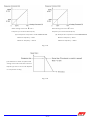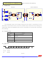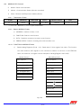
1
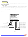
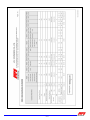
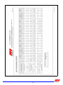
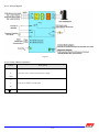
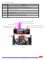
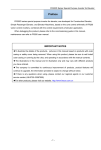
User's manual
BLDC DRIVER (Type B)
A.P.Y. ENGINEERING CO., LTD.
9/1 Moo 4, Soi Suksawat 62, Suksawat Rd., Kwang Bangmod, Khet Thoong-Kru
Bangkok 10140 THAILAND TEL: +66 2818 2995 FAX: +66 2818 2996, 2818 2997
Web site: http://www.apyeng.com , E-mail: [email protected]
MANUAL Version : E15
CONTENTS
CONTENTS
1
2
3
4
5
6
7
8
9
10
11
12
13
LIST OF CHANGE…………........…………………………………………………………….........
SAFETY INSTRUCTIONS………………............................................…………………….........
INTRODUCTION……………..………………………………............……………………….........
BLDC COMPRESSOR DRIVER SPECIFICATION…........................................………….........
THE FUNCTION BLOCK DIAGRAM OF FRECON COMPRESSOR DRIVER…........…..........
INSTALLATION AND WIRING……………………………………………...........………….........
NON-PROGRAMMABLE PARAMETERS OF BLDC COMPRESSOR DRIVER…….................
PROGRAMMABLE PARAMETERS OF BLDC COMPRESSOR DRIVER…….......……............
EXPLANATION OF NON-PROGRAMMABLE PARAMETERS……………...............................
EXPLANATION OF PROGRAMMABLE PARAMETERS………………....................................
OPERATION MODE SELECTION………………………………………..............................…...
RS485 MODBUS RTU COMMUNICATION……………………………..............................…...
EXPLANATION OF DRIVER’S FAULT………………….............................................…………
BL 1.9 Revision Date…19 Jul 2010…
1/35
2
3
7
11
12
14
20
20
21
24
25
27
34
1.1.LIST
LISTOF
OFCHANGE
CHANGE
Item
Description
1. External operation : When analog command ≤ 1.05V., frequency
command is 20Hz (F-00) for F003i-2SHB
and F003i-2PHB
External operation : When analog command ≤ 1.67V., frequency
2.
command is 60Hz (F-00) for other model
3. External operation : Emergency Stop
4. Address #3 : Hold frequency (60.00~360.00Hz) = 60.00Hz
5. Address #4 : Hold frequency time (0.0~6000.0sec.) = 0.0sec
6. Ordering Information : Ordering Code of Driver
(Compressor model, Maximum speed)
7. Standard Specifications : Add inverter type (F002i-2PHB, F008i-2PHB)
8. Revised ordering information : Table 1 Motor Specification (for BLDCM)
9. Revised standard specifications
10. Remark : The software trip level
11. Installation and Wiring : Installation Method
12. NON-PROGRAMMABLE PARAMETERS OF BLDC COMPRESSOR DRIVER :
“F-00, F-01, F-07”
13. OPERATION MODE SELECTION : “External operation, Fig. 11-3 and Fig 11-4”
14. Trip Type Address 1416 : PFC Converter Fault,
Heatsink temperature sensor error
15. Add “IPM or PFC module Temperature : Address 1420 (only F002i-2PHB,
F003i-2PHB, F007i-2PHB and F008i-2PHB)”
16. Add “IPM or PFC module temperature limit protection flow chart”
17. Explanation of Driver's Fault : Fault code “OH-1, PFC, Err1”
BL 1.9 Revision Date…19 Jul 2010…
2/35
Page Revision Date
25, 26 25 Dec.08
25, 26
25 Dec.08
25, 26
20, 24
20, 24
7
25 Dec.08
25 Dec.08
25 Dec.08
09 Dec. 09
11
8, 9
11
35
14
20
09 Dec. 09
01 Mar. 10
01 Mar. 10
01 Mar. 10
19 Jul. 10
19 Jul. 10
25, 26
19 Jul. 10
31
19 Jul. 10
32
19 Jul. 10
33
34
19 Jul. 10
19 Jul. 10
2.2.SAFETY
SAFETYINSTRUCTION
INSTRUCTION
This instruction manual gives handling information and precautions for use of this inverter. Incorrect
handling might cause an unexpected fault. Read this manual carefully before installing, connecting (wiring),
operating, servicing, or inspecting the inverter. Familiarize yourself with all safety features before using this
inverter. In this manual, safety messages are classified as follows:
WARNING
CAUTION
Improper operation may result in serious personal injury or death.
Improper operation may result in slight to medium personal injury or property damage.
Note that the CAUTION level may lead to a serious consequence according to conditions. Please follow the
instructions of both levels because they are important to personal safety.
2.1 Instructions on Use
WARNING
• This driver is designed to drive a brushless dc compressor and is not suitable for a single phase motor or
others, as fire may result.
• This driver may not be used as a component of a life-support system or other medical device directly
affecting the personal welfare of the user.
• Safety equipment must be installed or the failure of this device may result in personal injury, property
damage, or if there is a risk of accident.
2.2 Instructions on Installation
WARNING
• Mount this driver on an incombustible material such as metal. Installing the inverter directly on or near a
combustible or flammable material could lead to a fire.
CAUTION
• Do not hold or carry this driver by its cover, it may fall off.
• Do not drop the driver, as injury may result.
• Ensure that the driver and heat sink surfaces are kept free of foreign matter (lint, paper dust, small chips of
wood or metal, and dust), as fire or accident may result.
• Do not install or operate a damaged driver or an driver with missing parts, as electric shock or injury may
occur.
BL 1.9 Revision Date…19 Jul 2010…
3/35
2.3 Instructions on Wiring
WARNING
• Connect the driver to power via a line-protection molded-case circuit breaker or fuse, as fire may result.
Always connect a ground wire, as electric shock or fire may result.
• A licensed specialist must perform all wiring work, as electric shock may result.
• Turn off the power before wiring, as electric shock may result.
• Always install the driver before wiring, as electric shock or injury may occur.
CAUTION
• Confirm that the phases and rated voltage of this driver match those of the AC power supply, as injury may
result.
• Do not connect the output cables (U, V, W) to the AC power supply, as damage may result.
• Do not fit capacitive equipment such as a power factor correction capacitor, noise filter or surge suppressor
to the output of the driver.
• The connection orientation of the output cables (U, V, W) to the compressor will affect the direction of
rotation of the compressor.
• Ensure that the noise generated by the driver, compressor, or wiring does not adversely affect peripheral
sensors and equipment, as accident may result.
2.4 Instructions on Operation
WARNING
• Be sure to install the front cover before turning on the power. Do not run the driver with the front cover
removed. Electric shock may occur.
• Do not operate switches with wet hands, as electric shock may result.
• Make sure that the start signal is off before resetting the inverter alarm. A failure to do so may restart the
compressor suddenly.
• Do not touch driver terminals when energized, even if the driver has stopped. Electric shock may result.
BL 1.9 Revision Date…19 Jul 2010…
4/35
CAUTION
• Do not start or stop the driver using the main circuit power. Failure may result.
• Do not touch the heat sink because they become very hot. Burns may result.
• The driver can be easily set for high-speed operation. Before changing its setting, examine the performance
of the compressor and machine. Injury may result
• The electronic over current protection does not guarantee protection of the compressor from overheating.
• Before running the driver which had been stored for a long period, always perform inspection and test
operation.
2.5 Instructions on Maintenance, Inspection and Replacement
WARNING
• Wait a minimum of 5 minutes after power has been turned off before starting inspection. Also confirm that the
charge lamp is off and that DC voltage between terminals P and N does not exceed 25V Electrical shock
may result.
• Only authorized personal should perform maintenance, inspection, and replacement operation. Remove all
metal jewelry such as watches and rings. Use insulated tools only. Electric shock or injury may result.
CAUTION
• Do not carry out a megger (insulation resistance) test on the control circuit of the driver.
2.6 Instructions on Disposal
CAUTION
• Treat as industrial waste when disposing of driver.
2.7 Other Instructions
WARNING
• Never modify the product. Electric shock or injury may result.
BL 1.9 Revision Date…19 Jul 2010…
5/35
2.8 Conformity to Low Voltage Directive in Europe
CAUTION
• The ground terminal should be connected to ground. Use a crimp terminal to connect a cable to the main
circuit terminal or driver ground terminal.
• Use a single cable to connect the driver ground terminal. Do not use more driver ground terminals.
• Use a molded-case circuit breaker (MCCB) and magnetic contactor (MC) that conform to EN or IEC
standards.
• Operate the driver under over-voltage Category III conditions and maintain pollution Degree 2 or better as
specified in IEC664. To maintain Pollution Degree 2 or better, install the driver in a control panel structure
(level NEMA 3 or higher) which is free from water, oil, carbon, dust etc.
• To ensure safety, install an optional AC reactor, DC reactor as follows:
1) Install inside an IP4X cabinet or barrier if electrical parts are exposed.
2) Install inside an IP2X cabinet or barrier if electrical parts are not exposed.
2.9 General Instructions
•
For clarity, some figures in this manual may show the driver without covers for explanation purpose. Do
not operate the device until all such covers have been replaced.
The time required for the capacitors to discharge after the removal of
power from the equipment. Capacitor discharge time: Min. 5 minutes
BL 1.9 Revision Date…19 Jul 2010…
6/35
3.3.INTRODUCTION
INTRODUCTION
Thank you for choosing this FRECON BLDC compressor driver. This driver uses 32 bit CPU for multifunction in a variety of applications.
3.1 Driver inspection
Please inspect the following points after unpacking your driver. If you have any problems or questions
regarding the driver, please contact A.P.Y. Engineering Co., Ltd. or the distributor you purchased the unit from.
1) Check the nameplate on the driver cover to ensure that the specifications correspond to those you ordered.
2) Inspect visually if during shipping the unit have got any damage or disconnection on the parts or bent on cover
on main unit panels.
Ordering Information
F 015 i - 4
T
H
01
A
A : Maximum Speed = 130 rps
B : Maximum Speed = 120 rps
C : Maximum Speed = 110 rps
D : Maximum Speed = 95 rps
E : Maximum Speed = 90 rps
F : Maximum Speed = 80 rps
G : Maximum Speed = 60 rps
H : Maximum Speed = 100 rps
Compressor Model (See table 1)
A : For AC Induction compressor
B : For DC Induction compressor
H : H Series
X : X Series
FRECON
Size of Inverter 2HP – 20HP
IPM
2 : Power Supply 220V
4 : Power Supply 380V
S : Input Supply Single phase (Diode Rectifier)
T : Input Supply Three phase (Diode Rectifier)
P : Input Supply Single phase (PFC Converter)
Fig. 2-1
BL 1.9 Revision Date…19 Jul 2010…
B
7/35
BL 1.9 Revision Date…19 Jul 2010…
8/35
BL 1.9 Revision Date…19 Jul 2010…
9/35
3.2 Product warranty
This product is guaranteed against defects in workmanship for 12 months from the purchasing date.
However, the troubles caused by the following reasons are not covered by this warranty even in warranty period.
1) Problems caused by incorrect operation or by unauthorized repairs or modifications.
2) Problems resulting from using the driver in the range outside the standard specification.
3) Damage to the driver after purchase or during delivery.
4) Damage caused by earthquakes, fire, floods, lightning, abnormal voltage fluctuations or other natural disasters
and secondary disasters.
5) Damage caused by water.
6) Damage caused by animal or insect.
7) The external case or parts are damaged.
8) Damage caused by intention, accident or carelessness
BL 1.9 Revision Date…19 Jul 2010…
10/35
BLDC COMPRESSOR DRIVER SPECIFICATION
4.4.BLDC
BLDCCOMPRESS
COMPRESSDRIVER
DRIVERSPECIFICATION
SPECIFICATION
Inverter type
Inverter
Control
method
Power
Supply
Converter
Inverter
Method
Voltage
Frequency
Environment
Agency
Certification
220V series
F007i-2PHB F008i-2PHB
1 ∅ PFC
1 ∅ PFC
MAX.30 Arms MAX.36Arms
Size (mm.)
(WxHxD)
Weight (kg.)
Cooling
Ambient
Temperature
Storage
Temperature
Vibration
F008i-2SHB
F010i-2SHB
1 ∅ Diode Rectifier
F010i-2THB
3 ∅ Diode
Rectifier
F005i-4THB
F008i-4THB
1 ∅ 200 - 240 V~
380V series
F010i-4THB
F015i-4THB
F020i-4THB
25 Arms
34 Arms
3 ∅ Diode Rectifier
3 ∅ IPM Inverter
Sensorless Vector Control Method
3 ∅ 200 - 240 V~
50/60 Hz
Tolerance
Operating
Revolution
PWM
Control Carrier Frequency
Output Current
Protection
Method
Communication Baud rate
Format
Structure
F002i-2PHB F003i-2PHB F005i-2SHB
1 ∅ PFC
1 ∅ Diode
1 ∅ PFC
MAX.16 Arms MAX.20 Arms Rectifier
3 ∅ 360 - 460 V~
Voltage +10/-15% , Frequency ± 5%
10 - 130 rps (depend on motor specification ; see table 1)
9 Arms
13 Arms
4 kHz
17 Arms
22 Arms
25 Arms
25 Arms
34 Arms
34 Arms
10 Arms
14 Arms
18 Arms
Fin over heat, Over current, Under/over voltage, Overload, Compressor connection loss, Communication loss, PFC converter fault
Asynchronous Half Duplex
1200 bps
8-N-1 (8 data bits, none parity bit, 1 stop bit)
314x165x170 314x165x170 372x215x150 372x215x150 372x215x150 372x215x150 372x225x190
5.3
5.3
11
12
11
372x215x150
Under
developed
Under
developed
-
-
12
16
12
AL Fin Mounting and Forces Air Cooling
-20 to +70°C, 30 to 80% RH (Don’t condense, don’t freeze)
-20 to +80°C, 25 to 85% RH (Don’t condense, don’t freeze)
Max. 5.9 m/s2 (0.6g), 10 to 55 Hz
The drive is designed to meet applicable requirements of the following codes/standards:
EN61800-5-1 Adjustable speed electrical power drive systems - P.5-1: Safety requirements-electrical, thermal and energy
Marked for all applicable European Directives EMC Directive (89/336/EEC)
Emissions: EN 61800-3 Adjustable Speed electrical power drive systems Part 3
Immunity: EN 61800-3 Second Environment, Restricted Distribution Low Voltage Directive (73/23/EEC)
BL 1.9 Revision Date…19 Jul 2010…
11/35
334x215x150 334x215x150 372x215x150
11.5
11.5
13
5.5.THE
THE FUNCTION
FUNCTIONBLOCK
BLOCKDIAGRAM
DIAGRAMOF
OFFRECON
FRECONCOMPRESSOR
COMPRESSORDRIVER
DRIVER
Fig.5-1
Fig. 5-2
BL 1.9 Revision Date…19 Jul 2010…
12/35
Fig. 5-3
Fig. 5-4
BL 1.9 Revision Date…19 Jul 2010…
13/35
6.6.INSTALLATION
INSTALLATIONAND
ANDWIRING
WIRING
6.1 Operating Environment
Install this driver in location that meets the conditions as follow.
Item
Specifications
Location
Inside the cabinet (a well-ventilated room)
Ambient Temperature -20°C to +70°C (-4°F to +158°F)
Relative Humidity
30 to 80 % (Don’t condense, don’t freeze)
The driver must not be exposed to dust, direct sunlight, corrosive gas, explosive gas,
inflammable gas, oil mist, vapor, or water. There must be minimum salt content in the
Atmosphere
atmosphere. Do not store where condensation may occur as a result of sudden
changes in temperature
1000 m (3300 feet) or lower. After that derate by 3% for every extra 500 m up to 3000 m
Altitude
(88%)
Vibration
Max. 5.9 m/s2 (0.6g), 10 to 55Hz
6.2 Installation Method
• Install the driver securely with screws or bolts in the vertical direction. Do not turn the driver upside
down or install in a horizontal position. The cooling air should flow through heat sink, reactor and box of
driver to extend lifetime of driver. (see Fig. 6-1 (b))
•
Since heat is generated during drive operation, the spaces shown in Fig. 6-1 (a) are required to ensure
sufficient cooling. Do not install the driver beneath a device sensitive to heat as heat radiates upward.
• The heat sink and reactor may reach a temperature of 90°C and 125°C during driver operation. Ensure
that the material surrounding the product can withstand this temperature.
• Consider ventilation inside the cabinet to prevent the drive’s ambient temperature from exceeding the
specified value. Do not install the product in an area from which heat can not be sufficiently released.
• If two or more driver must be installed in the same cabinet, arrange the units horizontally to minimize the
effect of heat. If two or more driver must be installed vertically, place an insulated plate between the
driver to minimize the effect of heat.
BL 1.9 Revision Date…19 Jul 2010…
14/35
(a)
(b)
Fig. 6-1
6.3 Wiring Method
6.3.1 Wiring of the main circuit
1) Crimping terminals with insulation sleeves are recommended for use with the power and compressor
cables.
2) Check that the power supply voltage is within the maximum allowable voltage marked on the nameplate
of the driver. Connect the AC power input cables (R, S, T, or L, N) to the power supply via a mold-case
circuit breaker for circuit protection.
3) Check that the voltage, current and power of compressor are within the maximum allowable capacity
marked on the nameplate of the driver. Connect the driver output cables (U, V, W) to a 3-phase
compressor in correct phase sequence.
4) Power supply must not be applied to the output cables (U, V, W) of the driver. Otherwise the driver will be
damaged.
5) After wiring, wire off-cuts must not be left in the driver. Wire off-cuts can cause a fault, failure or
malfunction. Always keep the driver clean. When drilling mounting holes in a control box etc., exercise
care to prevent chips and other foreign matter from entering the driver.
6) Use cables of the recommended size for wiring to make the voltage drop 2 % or less. If the wiring
distance is long between the driver and compressor, a cable voltage drop will cause the motor torque to
decrease especially at the output of low frequency.
7) Do not install a power factor correction capacitor or surge absorber in the output side of the driver.
8) Do not connect a magnetic starter or magnetic contactor to the output side of the driver. If the load is
connected while the driver is running, the driver over current protective circuit operates because of inrush
current.
BL 1.9 Revision Date…19 Jul 2010…
15/35
9) The driver should not be operated/stopped by opening/closing the magnetic contactor at the input side
of the driver. Frequent switching may cause the driver to malfunction.
10) When rewiring after operation, make sure that the power lamp has gone off, and when more than 10
minutes have elapsed after power-off, check with a tester that the voltage is zero. After that, start
rewiring work.
11) AC reactor should be connected under the following condition.
• The capacity of the power supply transformer exceeds 500kVA and exceeds the rated capacity of
the drive tenfold. (See Fig. 6-2)
• Used to prevent the driver over voltage trip from occurring when the power factor capacitor in the
power line is switched on and off.
• When the voltage imbalance exceeds 3 %
Imbalance rate between phase [%] = (Max. voltage [V] – Min voltage [V]/3 phase average voltage [V]
Fig. 6-2
12) Do not run the power cables (input and output of the driver) and signal cables of the driver in parallel
with each other and do not bundle them.
13) If the cable from the in driver to the compressor is very long, a high-frequency current may be
generated by stray capacitance between the cables and result in an over current trip of the driver, an
increase in leakage current, or a reduction in current indication precision.
BL 1.9 Revision Date…19 Jul 2010…
16/35
6.3.2 Grounding instructions
1) Leakage currents flow in the driver. To prevent an electric shock, the driver and compressor must be
grounded (220V class …class 3 grounding, grounding resistance 100Ω maximum), (380V class …
special class 3 grounding, grounding resistance 10Ω or less).
2) Use the dedicated ground cable (E) to ground the driver.
3) When using several driver units side by side, ground the units as shown in (a) or (b) of Fig. 6-3. Do not
loop the ground wires as shown in (c).
INV.1
INV.2
INV.3
INV.1
INV.2
INV.3
INV.1
INV.2
INV.3
(a)
(b)
(c)
Fig. 6-3
6.3.3 Wiring of the control circuit
1) Separate control circuit wires from main circuit wires and other power cables to prevent erroneous
operation caused by noise interference.
2) Use twisted shield or twisted-pair shielded wire for the control circuit line and connect the shielded
sheath to the ground.
3) A wiring distance should be less than 20 m.
BL 1.9 Revision Date…19 Jul 2010…
17/35
6.3.4 Wiring Diagram
Fig. 6-4
6.3.5 Power Cables Connection
Cable
Description
R (L)
S
Connect to the commercial power supply
T (N)
U
V
Connect to BLDC compressor
W
(E)
Connect the driver chassis (case) to earth
BL 1.9 Revision Date…19 Jul 2010…
18/35
6.3.6 Control terminal connection
Terminal
RUN
0-10V
+12
OP1
CM
Tx/RxTx/Rx+
Description
Turn on to start compressor in external operation mode.
Analog input for frequency command in external operation mode.
DC power supply 12V 100mA
Fault signal output (Open Collector)
Control signal ground
Transmit/Receive – signal of RS485 communication
Transmit/Receive + signal of RS485 communication
6.3.7 Terminal Layout
Interface with APY Outdoor Control Board
External Run
Fault Output (Open Collector 100mA max)
Frequency Command 0-10Vdc
RS485 MODBUS RTU Communication
Pin4/5 = TxRx-/TxRx+
8
Connect Jumper: external Run & 0-10V Command
Remove Jumper: Modbus operation (Address 1408-1409)
1
Earth
Fig. 6-5
BL 1.9 Revision Date…19 Jul 2010…
19/35
7.7.NON
NON--PROGRAMMABLE
PROGRAMMABLEPARAMETERS
PARAMETERSOF
OFBLDC
BLDCCOMPRESSOR
COMPRESSORDRIVER
DRIVER
CODE
F-00
F-01
F-02
F-03
F-04
F-05
F-06
F-07
F-08
F-09
F-10
F-11
F-12
F-13
F-14
F-15
F-16
F-17
F-18
PARAMETER
DATA
For Compressor 4 Pole
For Compressor 6 Pole
30.00Hz or 60.00Hz
Minimum frequency
20.00Hz
(depend on compressor model)
Maximum frequency
Depend on Compressor model
Acceleration time 1 (start interval)
12.5 sec. (2 rps/sec.)
8.3 sec. (2 rps/sec.)
Acceleration time 2 (normal operation)
12.5 sec. (2 rps/sec.)
8.3 sec. (2 rps/sec.)
Deceleration time 1 (normal operation)
12.5 sec. (2 rps/sec.)
8.3 sec. (2 rps/sec.)
Deceleration time 2 (deceleration to stop) 12.5 sec. (2 rps/sec.)
8.3 sec. (2 rps/sec.)
Start frequency
0.50Hz
0.50Hz
30.00Hz or 60.00Hz
Stop frequency
20.00Hz
(depend on compressor model)
Thermal overload level
100 % of rated current
100 % of rated current
Current limit with frequency level
100 % of rated current
100 % of rated current
Band of current limit
4 % of rated current
4 % of rated current
Deceleration time when current limit active 12.5 sec. (2 rps/sec.)
8.3 sec. (2 rps/sec.)
Node address for MODBUS
1
1
Baud rate
1200 bits/sec.
1200 bits/sec.
Data format
8-N-1
8-N-1
Reply interval
10 ms.
10 ms.
Communication loss time out
5 sec.
5 sec.
Time out action for MODBUS
Deceleration to stop
Deceleration to stop
Switching frequency
4kHz
4kHz
Note :
• User can see compressor model in Table 1
• User can not change the above parameter by keypad or MODBUS communication
• If user want to change it, please contact A.P.Y.ENGINEERING Co., Ltd.
8.8.PROGRAMMABLE
PROGRAMMABLEPARAMETERS
PARAMETERSOF
OFBLDC
BLDCCOMPRESSOR
COMPRESSORDRIVER
DRIVER
CODE
P-03
P-04
PARAMETER
Hold frequency (Address #3)
Hold frequency time (Address #4)
DATA
60.00 ~ 360.00Hz.
0.0 ~ 6000.0 sec.
DEFAULT
60.00
0.0
Note: User can change the above parameter by MODBUS communication. (Address #3 and address #4)
BL 1.9 Revision Date…19 Jul 2010…
20/35
9.9.EXPLANATION
EXPLANATIONOF
OFNON
NONPROGRAMMABLE
PROGRAMMABLEPARAMETERS
PARAMETERS
F-00: Minimum frequency
F-01: Maximum frequency
Output frequency of compressor driver can be limited by minimum frequency and maximum frequency (F-00 and F-01).
Frequency command via RS485 :
If frequency command < F-00, output
frequency = 0 (stop)
Frequency command via analog command
(0-10 Vdc) :
If frequency command < F-00, output
frequency = F-00
Fig. 9-1
F-02:
F-03:
F-04:
F-05:
F-06:
F-07:
Acceleration time 1 (start interval)
Acceleration time 2 (normal operation)
Deceleration time 1 (normal operation)
Deceleration time 2 (deceleration to stop)
Start frequency
Stop frequency
Acceleration time = A time to accelerate frequency from 0.00Hz to 50.00Hz (reference frequency).
Deceleration time = A time to decelerate frequency from 50.00Hz (reference frequency) to 0.00Hz
Example User want to increase frequency from 0.00Hz to 100.00Hz within 5 sec, the acceleration time must be set
= 2.5 sec. or user want to decrease frequency from 100.00Hz to 0.00Hz within 10 sec, the deceleration time
must be set = 5 sec.
Fig. 9-2
BL 1.9 Revision Date…19 Jul 2010…
21/35
The start frequency of compressor is 0.5Hz (F-06).The frequency increase from 0.5Hz to 15Hz within 1.45
sec. After that it increases from 15Hz to hold frequency (P-03 = 60.00Hz) by acceleration time1 (F-02) and
remains stable for hold frequency time (P-04 = 0.0 sec.) before reaching to the target frequency by acceleration
time2 (F-03).
When the target frequency is decreased, the frequency will be decreased by deceleration time1 (F-04.).
When the compressor is stopped, frequency will be decreased to stop frequency (F-07) by deceleration time2 (F05). After that the compressor is free run. Refer to the diagram below.
Fig. 9-3
F-08: Thermal overload level
The electronic thermal overload protection in the inverter detects motor overheat due to overload. If the
thermal overload level (F-08) is 100% of rated current, when a current more than 100% of rated output current
flows, inverse-time characteristic cause the electronic thermal overload protection to be activated to stop the
inverter output. (overload immunity: 150% of rated current in 1 minute)
Fig. 9-4
BL 1.9 Revision Date…19 Jul 2010…
22/35
F-09: Current limit with frequency level
F-10: Band of current limit
F-11: Deceleration time when current limit active
Current limit with frequency protection will be activated when compressor current more than rated current
(F-09 = 100% of rated current.). The protected operation and condition to stop protection can be shown as
following.
Irate = Rate current
I = Compressor current
Imin = [(100 - band in F-10) x Irated] / 100
Freq. = Operating frequency
Freq.com = Frequency command
Fig. 9-5
BL 1.9 Revision Date…19 Jul 2010…
23/35
F-12: Node address for MODBUS
The address of inverter for MODBUS communication. (See more detail in communication Protocol)
F-13: Baud rate
Baud rate is the rate of transmission or receiving data. (See more detail in communication Protocol)
F-14: Data format
Data format is the format in a frame of transmission / receiving data. The format 8-N-1 can be shown as
following.
8 = 8 bits data length
N = none parity bit
1 = 1 stop bit
(See more detail in communication Protocol)
F-15: Reply interval
When the inverter receives data command from communication, there is some delay time before the reply
of inverter. This delay time is reply interval.
F-16: Communication loss time out
It is the time that the inverter will remain in communication loss before implementing the action in F-17.
F-17: Time out action for MODBUS
It is the inverter’s response to a loss of the communication connection or excessive communication errors.
F-18: Switching frequency
User can adjust motor noise by changing the switching frequency. A reduced switching frequency will
decrease leakage current but increase motor noise.
10.
10.EXPLANATION
EXPLANATIONOF
OFPROGRAMMABLE
PROGRAMMABLEPARAMETERS
PARAMETERS
P-03: Hold frequency
P-04: Hold frequency time
Start up frequency of compressor is 0.5Hz The frequency increase from 0.5Hz To “hold frequency” (P-03)
And remains stable for “hold frequency time” (P-04). After that the frequency will accelerate to the target with 2 rps/sec.
Fig. 10-1
BL 1.9 Revision Date…19 Jul 2010…
24/35
11.
11.OPERATION
OPERATIONMODE
MODESELECTION
SELECTION
11.1 RS485 operation with MODBUS RTU: Remove Jumper “MD” on main board (see wiring diagram)
The FRECON driver has ability to communicate with the MODBUS RTU protocol via the RS485
communication link, which is one of the favorite industrial communications. In this mode, the driver receives
frequency and control command from outdoor controller in order to drive the BLDC compressor. (See detail in
Communication Protocol)
Fig. 11-1
11.2 External operation: Connect Jumper “MD” on main board (see wiring diagram)
In this mode, the driver has 2 inputs and 1 output connector to command compressor. The frequency
command (0.00~maximum frequency) receives from analog command (0-10Vdc) see Fig. 11-3. The compressor
can be run by closing the external run switch and stop compressor or reset fault by opening this switch. When the
analog command (0-10Vdc) is less than minimum frequency (0.91V or 1.67V or etc depend on compressor model)
and the external run switch is opened, the frequency will be decreased to zero immediately (emergency stop) see
Fig. 11-4. The outdoor controller can receive fault signal from OP1 connector. (See detail in Wiring Diagram of
BLDC driver)
Fig. 11-2
BL 1.9 Revision Date…19 Jul 2010…
25/35
When analog command ≤ 0.91V,
Frequency command is 20Hz (F-00)
(a) Example for compressor model TNB220FLHMT
Minimum frequency = 20Hz
Maximum frequency = 220Hz
Fig. 11-3
[The external run switch is opened and
analog command is less than minimum
frequency (0.91V or 1.67V or etc depend
on compressor mode)]
Fig. 11-4
BL 1.9 Revision Date…19 Jul 2010…
26/35
When analog command ≤ 1.67V,
Frequency command is 60Hz (F-00)
(b) Example for compressor model ANB42FBEMT
Minimum frequency = 60Hz
Maximum frequency = 360Hz
12.
12.RS485
RS485MODBUS
MODBUSRTU
RTUCOMMUNICATION
COMMUNICATION
(See more information in www. Modbus.org
12.1 Interface Circuit
Outdoor controller side
Driver side
VCC
2K
TLP 521
RXD
+5
From MCU
VCC
1K
10
+5
2K2
SN75176
2K
VCC
TLP 521
1
2
3
4
1K
TXD
R
RE
DE
D
RS485
103
+5
VCC
B
A
GND
1
1
3
3
5
5
2
8
7
6
5
TX/RX-
4
TX/RX+
6
+5M
7
2K2
10
SN75176
VCC
4
TX/RX-
6
TX/RX+
8
7
6
5
7
+5M
VCC
B
A
GND
R
RE
DE
D
1
2
3
4
RXD
Dir
TXD
8
Mod BUS
+5
103
2
8
From MCU
10
RS485
Mod BUS
2K2
2K2
103
VCC
10
TLP 521
10
103
103
1K
Dir
From MCU
Fig. 12-1
The communication system must be wiring be wiring by the 2-line cable. It’s recommended to use the
shield cable for noise reduction and may connect the termination resister, which has the value matching to the
cable (normally 120Ω), at the beginning and the end of the communication line if necessary (the communication
link in quite long)
12.2 Transmission Type
Items
Method
Baud Rate
Data Bit Length
Parity Bit
Stop Bit Length
12.3 Data Format
8–N–1
ST D0
D1
ST
: Start Bit
D0~D7 : Data Bit
SP
: Stop Bit
BL 1.9 Revision Date…19 Jul 2010…
Content
Asynchronous Half Duplex
1200 bps
8 bit
None
1 bit
D2
D3
D4
D5
Fig. 12-2
27/35
D6
D7
SP
12.4 MODBUS RTU Protocol
• Master / Slave communication
•
Master: Communication Starter (Outdoor controller)
•
Slave: Receive and Response to Master (Driver)
12.4.1 Transmission Frame
START
ADDRESS
FUNCTION
DATA
T1 – T2 – T3 – T4
8 BITS
8 BITS
N x 8 BITS
T1-T2-T3-T4: Wait time = 3.5 of 1 bytes transmission
ERROR CHECK
16 BITS
END
T1 – T2 – T3 – T4
12.4.2 Data in MODBUS Frame
1) ADDRESS: Address of slave 1–247
2) FUNCTION: Read or write function
3) DATA: Data that correspond to read or write function
4) ERROR CHECK: Data for checking the communication error
12.4.3 FUNCTION in MODBUS Frame
1) Read Holding Registers (Code = 03): Read data of 16 bit register from slave. This function
can read maximum 255 registers in the continuous address at one time. In the FRECON
driver, the maximum 18 register can be read (when reading Register 1408-1425)
Master (Query)
Slave Address
Function (3)
Start Address (Hi)
Start Address (Lo)
No. of Register (Hi)
No. of Register (Lo)
Error Check
Slave (Response)
Slave Address
Function (3)
Data Byte Count
Data 1 (Hi)
Data 1 (Lo)
Data 2 (Hi)
Data 2 (Lo)
Data N (Hi)
Data N (Lo)
Error Check
Fig. 12-3
BL 1.9 Revision Date…19 Jul 2010…
28/35
2)
Preset Single Register (Code = 06): Write single data to 16 bit register of slave.
Master (Query)
Slave Address
Function (6)
Register Address (Hi)
Register Address (Lo)
Preset Data (Hi)
Preset Data (Lo)
Error Check
Slave (Response)
Slave Address
Function (6)
Register Address (Hi)
Register Address (Lo)
Preset Data (Hi)
Preset Data (Lo)
Error Check
Fig. 12-4
3)
Preset Multiple Register (Code = 16): Write multiple data to 16 bit registers of slave. This
function can write maximum 8 register in the continuous address at one time.
Master (Query)
Slave Address
Function (16)
Start Address (Hi)
Start Address (Lo)
No. of Register (Hi)
No. of Register (Lo)
Data Byte Count
Preset Data 1 (Hi)
Preset Data 1 (Lo)
Preset Data 2 (Hi)
Preset Data 2 (Lo)
Slave (Response)
Slave Address
Function (16)
Start Address(Hi)
Start Address(Lo)
No. of Register (Hi)
No. of Register (Lo)
Error Check
Preset Data N (Hi)
Preset Data N (Lo)
Error Check
Fig. 12-5
BL 1.9 Revision Date…19 Jul 2010…
29/35
12.4.4 Read / Write Register List
1) Frequency command: Address 1408 (User can write this register when jumper “MD” on main
board has been removed; see operation mode selection)
0 – 36000: 0.00 – 360.00Hz
2) Control Command: Address 1409 (User can write this register when jumper “MD” on main
board has been removed; see operation mode selection)
Bit 0: Run / Stop compressor 0 = Stop, 1= RUN
Bit 1: Emergency stop 0 = Disable, 1 = Enable
Bit 2: Reset fault 0 = Disable, 1 = Enable
Bit 3 – 15: Reserve
Fig. 12-6
3) Reserve : Address 1410 – 1414
12.4.5 Read Only Register List
1) Outdoor unit Status: Address 1415
Bit 0: Stop / Run mode 0 = Stop mode, 1 = Run mode
Bit 1: Normal / Trip mode 0 = Normal mode, 1 = Trip mode
Bit 2: Steady state 0 = Not steady state, 1 = Steady state
Bit 3: Acceleration state 0 = Not Acceleration state, 1 = Acceleration state
Bit 4: Deceleration state 0 = Not Deceleration state, 1 = Deceleration state
Bit 5 – 11: Reserve
Bit 12: Compressor oil return state 0 = Not complete, 1 = Complete
Bit 13: Compressor speed decelerate by protection 0 = Not active, 1 = Active
Bit 14: Compressor is not connected warning 0 = Normal, 1 = Warning
Bit 15: Reserve
BL 1.9 Revision Date…19 Jul 2010…
30/35
“NC Warning Flow chart”
Fig. 12-7
2) Trip Type: Address 1416
Value = 0: Not trip
Value = 1: Heatsink over heat
Value = 2: Over current at acceleration state (Hardware trip)
Value = 3: Over current at steady state (Hardware trip)
Value = 4: Over current at deceleration state (Hardware trip)
Value = 5: DC Bus under voltage
Value = 6: DC Bus over voltage
Value = 7-8: Reserve
Value = 9: PFC Converter Fault (only F002i-2PHB, F003i-2PHB, F007i-2PHB and F008i-2PHB)
Value = 10: Over current at acceleration state (Software trip)
Value = 11: Over load fault
Value = 12: Over current at steady state (Software trip)
Value = 13: Over current at deceleration state (Software trip)
Value = 14: Reserve
Value = 15: Communication loss time out
Value = 16: Heatsink temperature sensor error (only F002i-2PHB, F003i-2PHB, F007i-2PHB and F008i-2PHB)
Value = 17-19: Reserve
Value = 20: Abnormal condition
BL 1.9 Revision Date…19 Jul 2010…
31/35
3) Operating Frequency of compressor: Address 1417
0 ~ 36000: 0.00 – 360.00Hz
4) IPM or PFC module Temperature: Address 1420 (only F002i-2PHB, F003i-2PHB, F007i-2PHB and
F008i-2PHB)
-200 ~ 1800: -20.0 ~ 180.0°C
5) Compressor Current: Address 1422
0 ~ 450: 0.0 ~ 45.0 Arms
6) Output voltage: Address 1423
0 ~ 400: 0 ~ 400 Vrms
7) DC Bus voltage: Address 1424
0 ~ 800: 0 ~ 800V
8) Estimated speed: Address 1425
0 ~ 36000: 0 ~ 360.00Hz
Fig. 12-8
BL 1.9 Revision Date…19 Jul 2010…
32/35
IPM or PFC module temperature limit protection flow chart
(only F002i-2PHB, F003i-2PHB, F007i-2PHB and F008i-2PHB)
T = IPM or PFC module Temperature (address 1420)
Freq. = Operating frequency
Freq.com= Frequency command
Fig. 12-9
BL 1.9 Revision Date…19 Jul 2010…
33/35
13.
13.EXPLANATION
EXPLANATIONOF
OFDRIVER'S
DRIVER'SFAULT
FAULT
Address
#1416
1
2
3
4
5
6
7-8
9
10
11
12
13
14
15
16
Fault
code
OH-1
Description
Corrective action
IPM module over heat (100 ~ 125°C )
PFC module over heat ( > 95°C )
OC-A Over current or output short circuit during
Speed acceleration (hardware trip)
OC-C Over current or output short circuit during
Speed steady state (hardware trip)
OC-d Over current or output short circuit during
Speed deceleration (hardware trip)
-LU- DC bus under voltage
220V series: 175Vdc
380V series: 310Vdc
-OU- DC bus over voltage
220V series: 400Vdc
380V series: 800Vdc
Reserve
PFC PFC Converter fault (only F002i-2PHB,
F003i-2PHB, F007i-2PHB and F008i-2PHB)
1. Check cooling fan
2. Check ambient temperature
1. Check motor coil resistance
2. Check motor insulation
1. Check the same as OC-A
1. Check the same as OC-A
1. Check input voltage level
2. Check power source and wiring
3. Check pre-charge contactor
1. Check input voltage level
2. Check power source and wiring
1. Check reactor inductance
2. Check reactor insulation
3. Check bus voltage capacitor
1. Check the same as OC-A
oc_A
Over current or output short circuit during
Speed acceleration (Software trip)
-OL- Output current exceeded the electronic
thermal overload level for a long time
(150% of rated in 60 sec.)
oc_C Over current or output short circuit during
Speed steady state (software trip)
oc_d Over current or output short circuit during
Speed deceleration (software trip)
Reserve
-tOModbus communication loss time out
Err 1
1. Reduce the load compressor
2. Increase the capacity of driver appropriately
1. Check the same as OC-A
1. Check the same as OC-A
Heat sink temperature sensor error
(only F002i-2PHB, F003i-2PHB, F007i-2PHB and F008i-2PHB)
BL 1.9 Revision Date…19 Jul 2010…
34/35
1. Check signal of TxRx+/TxRx- (Pin4/5 of
Modbus connector)
2. Check communication signal of outdoor
controller
1. Check heat sink temperature sensor wiring
Address Fault
Description
#1416
code
17-19 Reserve
20
AbnC Abnormal condition (frequency decelerate to stop by current
limit protection or heatsink temperature protection
Corrective action
1. Check cooling fan
2. Check air–condition system
Remark:
• OC-A, OC-C and OC-d are hardware trip. The trip level depends on IPM power module.
• oc_A, oc_c and oc_d are software trip. The trip level are as following.
F005i-4THB (10 Arms. 380V): 25 Apeak. instantaneously.
F008i-4THB (14 Arms. 380V): 35 Apeak. instantaneously.
F010i-4THB (18 Arms. 380V): 50 Apeak. instantaneously.
F015i-4THB (25 Arms. 380V): 50 Apeak. instantaneously.
F020i-4THB (34 Arms. 380V): 75 Apeak. instantaneously.
F002i-2PHB (9 Arms. 220V): 20 Apeak. instantaneously.
F003i-2PHB (13 Arms. 220V): 30 Apeak. instantaneously.
F007i-2PHB (22 Arms. 220V): 50 Apeak. instantaneously.
F008i-2SHB (25 Arms. 220V): 50 Apeak. instantaneously.
F008i-2PHB (25 Arms. 220V): 50 Apeak. instantaneously.
F010i-2SHB (34 Arms. 220V): 75 Apeak. instantaneously.
F010i-2THB (34 Arms. 220V): 75 Apeak. Instantaneously
• The difference between over current (OC-A,OC-C,OC-d,oc_A,oc_c and oc_d) and overload (-OL-) is
: Over current is the instantaneous trip.
: Overload is not instantaneous trip. (Please see detail in manual page 22/35 ; F-08)
• LED indicator on main board shows as following
Stop mode: (slow blink) ON 1 sec. OFF 0.5 sec.
Trip mode: (Fast blink) ON 0.2 sec. OFF 0.2 sec.
Run mode: ON all time.
BL 1.9 Revision Date…19 Jul 2010…
35/35