1
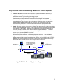
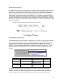
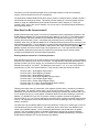
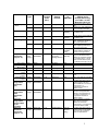
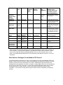
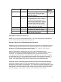
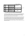
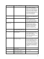
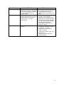
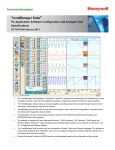
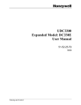
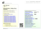
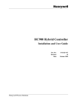
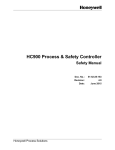
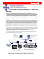
HC900 Hybrid Controller
When you need more than just discrete control
Stage Open Ethernet Connectivity via Modbus/TCP – Product Note
Background
Ethernet, or more exactly, Ethernet TCP/IP networks, operating at 10MBits/sec or higher, are
becoming increasingly popular in an industrial production environment. This is due to their speed,
versatility, and commonality with other business level networks based on the same networking
standards within a plant location. Many industrial level products now offer an Ethernet interface,
either direct to the equipment or through a hardware bridge. The protocols used within this Ethernet
environment are an important factor in connectivity between a software package running in a PC
and the field hardware.
A Modbus RTU protocol interface has been used as a defacto standard for many years in lower
speed, RS-485 serial network applications and is available for most of Honeywell’s data recording
and control products. A relatively new protocol standard gaining popularity, Modbus/TCP (also
called Modbus TCP/IP), is now available as a communications driver in many popular software
application packages used for operator interface and data acquisition. Modbus/TCP combines the
Modbus RTU protocol with Ethernet TCP/IP, allowing data access over an Ethernet LAN (Local
Area Network) connection. Since standard Modbus addressing is used, interfacing is well known.
HC900 controllers support the Modbus/TCP protocol as standard via a direct Ethernet connection.
This is also the case for Trendview paperless recorders. Honeywell’s other serial RS-485 Modbus
products such as UDC3300 controllers or UMC800 support the protocol via an external
Ethernet/Modbus bridge hardware device or an internal bridge card.
For reference, a section provided later in this document provides a review of Ethernet TCP/IP
networks and protocols and a Glossary of Terms.
Client or
2nd Application
Software Package
With Modbus/TCP
Driver
Application Software
with Modbus/TCP
Driver
To other network
segments
Ethernet/Modbus
Bridge
Switch
Hub or Switch
UDC3300
UMC800
DPR180
(Connection via Internal
Ethernet/Modbus Bridge)
HC900 Controllers
(Direct Ethernet Connection)
Trendview
Recorder
Fig. 1 Ethernet TCP/IP Network with 10Base-T Star Topology
1
Why is Ethernet communications using Modbus/TCP protocol important?
•
•
•
•
•
Customer demand - Ethernet LAN connection to application software is becoming a
requirement for many customers, most of which have business or production networks
using Ethernet with IT (Information Technology) support.
Growing popularity of Modbus/TCP over Ethernet – most HMI and data acquisition
software packages offer a Modbus/TCP driver, it is becoming an open standard
Modbus familiarity - Data access for read and write is via normal serial Modbus RTU
methods using the same function code and parameter definitions, known to many users.
Real-time data available in the HC900 such as control loop parameters, signal tags,
variables, analog inputs, etc. can be accessed real-time via the appropriate Modbus
address.
Speed – Ethernet networks (now normally 10Base-T star topology) offer higher speed data
access versus serial RS-485 networks. This is especially true for direct Ethernet-connected
products such as the HC900. Depending on Networks will not be slowed significantly as
more units are placed on the network due to Ethernet’s higher “bandwidth”. A 10Base-T
network offers 10MBits/sec. data rates although there is possible contention for network
access due to Ethernet CSMA/CD principles.
Ethernet Multi-Channel Support – Many applications can operate concurrently over an
Ethernet LAN between Ethernet “nodes” using separate “channels”. The HC900 can
support up to 5 concurrent connections to software applications. As an example, 2 separate
HMI packages, HC900’s Hybrid Control Designer software, a Visual BASIC and an EXCEL
application at different network locations can all address the same controller concurrently.
On the other hand, RS-485 supports only a single channel connection.
Application C
Multiple applications
can run concurrently
between nodes
Application A
Application B
Switch
Node
Nodes
Channels
HC900 Controllers
Fig. 2 –Multiple Channel Application Support
2
Modbus/TCP Protocol
The Modbus/TCP protocol was released publicly in 1999 by Groupe Schneider’s Modicon division to
provide open, vendor-independent access to PLC’s, I/O modules, Ethernet/Modbus bridges, or
other process instrumentation over Ethernet TCP/IP networks. This is simply an encapsulation of
Modicon’s Modbus RTU protocol within a TCP/IP frame as shown in Fig. 3. Function codes and
data registers are accessed the same as with Modbus RTU. The address in the Modbus frame is
set to 00 since addressing to direct Ethernet-connected devices utilizes the IP address. In addition,
there is no checksum for error checking since this is implemented at the TCP/IP network levels. The
specification is available for royalty-free licensing from Modicon. To review the specification, access
the Modicon website at:
http://www.modicon.com/openmbus/standards/openmbus.htm.
Fig. 3 Modbus/TCP frame
HC900 Modbus/TCP Setup
The HC900 Ethernet network connection for Modbus/TCP is inherent once the Ethernet IP address
for the controller host port is established. The HC900 predominantly uses an IEEE floating point
format for communicating data to software applications supported by Modbus/TCP protocol. A
floating point value is sent as (2) consecutive 16-bit registers, each register of which consists of two
8-bit bytes. Some software packages require the registers to be sent in a certain order. The HC
Designer software tool allows this order to be selected. The following table lists the selections
provided.
Selection
FB B
FB BB
FB L
FB LB
Register (Word) Order
First word High
First word low
Floating Pt Format
Big Endian (0,1,2,3)
Big Endian ByteSwapped (1,0,3,2)
Little Endian (3,2,1,0)
Little Endian ByteSwapped (2,3,0,1)
Comment
Default
Most
common
The Modbus TCP double register transmission format selection, FB LB “Little Endian ByteSwapped”, would be selected for interface to most third party software packages which use this
format as standard. Our default, FB B “Big Endian” is used with SpecView32 or PlantScape
software and follows the “Honeywell” default format of other control and recording products.
3
Fortunately, most PC software packages offer a word swap selection in their driver package
anyway, so there should never be an incompatibility.
The application software Modbus/TCP driver (server) must be configured per the software vendor’s
documentation for dialog box entries. This usually involves setting up a communications channel
based on using an installed Ethernet NIC (Network Interface Card or adapter), a TCP/IP port
(default is 502), entry of the unit’s IP address, use (or non-use) of zero-based register addressing,
and connection timeout.
What Data Can Be Communicated?
HC900 controllers provide access to an array of parameters that are categorized by function in the
HC900 Ethernet Modbus/TCP Communications User’s Manual, 51-52-25-111. The HC900 retains
all of the Modbus addresses available for the UMC800 and expands the listing due to its greater
capacity and functionality. Table 1 summarizes this parameter access, including the read/write
capability, when using an Ethernet Modbus/TCP or Modbus Ethernet protocol driver (server) for the
host software application. The HC Designer tool also provides the Modbus addresses for all Signal
Tags and Variables plus the starting Modbus addresses for the major functions supporting a
Modbus address set such as control loops, SP programmers, etc. The Tag Information and the
Block Modbus Addresses reports may be viewed on-line and printed out for reference when
configuring the database for the host software application.
Entering Modbus Addresses in Third Party Software
After selecting the driver for the TCP/IP channel in a third party software package, the tag database
would then be created in some cases via a Wizard. The tag definition dialog box would have entries
typically for Data Type (Float, Integer, etc.) and decimal (or Hex) parameter addressing, typically
decimal with a range of 1 to 65535. The Modbus function code (1, 2, 3, 4, 16, etc.) may also be a
separate entry or part of the decimal address. These function codes are defined as follows:
Function Code 1: Read Digital Output Status
Function Code 2: Read Digital Input Status
Function Code 3: Read Holding Registers
Function Code 4: Read Input Registers (Analog Inputs)
Function Code 5: Force Single Digital Output
Function Code 6: Preset Single Register (Write)
Function Code 16 (10 hex): Preset Multiple Registers (Writes)
Function Code 17 (11 hex): Report HC900 ID
Floating point values take (2) consecutive 16-bit registers (32 bits) and it is normal to just address
the first register. For example, Analog Input 1 on an AI card (8 inputs) in Rack 1, Slot 1 would be
addressed, using function code 4, by entering 0000, Analog Input 2 would have address 0001, and
so on. Integers use only (1) 16-bit register. Sometimes the driver will add a leading 4 or 40 to the
address, e.g. 400065 for Loop1 PV, to represent “Holding” registers accessed using Modbus
Function Code 3, or a 3 or 30 to the address (to represent “Input” registers accessed using Function
Code 4). The application via the communications driver knows by data type how many registers to
obtain in sequence.
The table lists only the starting address for the first parameter of many for a certain type or for a set
of parameters such as for control loops. The addresses are the same as for the UMC800 to the
extent of the UMC800 capacity. There is extending addressing in the HC900 due to its greater
capacity. This necessitated creation of duplicate addressing to provide full contiguous address
space for some parameter types as noted. For further detail on Modbus addressing, consult the
HC900 Ethernet Modbus/TCP Communications User Manual.
4
Parameter
Analog Inputs
– AI’s
Data
Type
Access
Modbus
Function
Code
(Dec)
*Modbus
Starting
Address
Same
As
UMC800?
Comments
(Offsets are for
decimal addressing),
see Table 1 in User
Manual 51-52-25-111
First 8 slots (64 AI’s) of Rack 1
only
All AI’s (up to 128), addressed
on a consecutive rack basis
Float
Read
3
6145 (1800 h)
Yes
Float,
Read
4
0 (0 h)
No
Digital Inputs
Integer
Read
01
0 (0 h)
Yes, up to
capacity.
See 51-52-25-111 User Manual
for address map.
Digital Outputs
Integer
Read, Write
02,05
0 (0 h)
Signal Tags
Float
Read
3
8193 (2000 h)
Yes, up to
capacity.
Yes
Float
Read
3
15201 (3B60 h)
No
Variables
Float
Read/Write
3, 16
6337 (18C0 h)
Loop
Parameters
(approx. 50)
Float (&
some
Integer)
Read and
Read/Write
3, 16
65 (40 h)
(for Loop 1,
starting with PV)
Yes ( up to
Variable
150)
Yes ( up to
loop 16)
See 51-52-25-111 User Manual
for address map.
Access to Signal Tags 1 to
1000. Digital tags read as 0.0
and 1.0 for logic 0 and 1
Access to Signal Tags 1 to
2000. Digital tags read as 0.0
and 1.0 for logic 0 and 1
Access to Variables 1 to 600.
Digital Variables read/write as
0.0 and 1.0 for logic 0 and 1
PV, Loop 1
WSP (Working
SP), Loop 1
Output, Loop1
LSP (Local SP),
Loop1
Auto/Manual,
Loop 1
Remote/Local,
Loop 1
Set Point
Programmer
Parameters
(10)
Float
Float
Read
Read
3
3
65 (40 h)
69 (44 h)
Yes
Yes
Float
Float
Read/Write
Read/Write
3
3, 16
71 (46 h)
107 (6A h)
Yes
Yes
Integer
Read/write
3, 16
251 (FA h)
Yes
Integer
Read/write
3, 16
253 (FA h)
Yes
Float &
Integer
Read and
Read/Write
3, 16
7681(1E00 h)
Yes
Set Point
Programmer
Add.
Parameters
(15)
Float &
Integer
Read and
Read/Write
3, 16
7681(1E00 h)
Yes
Set Point
Programmer
Segment Data
(5 per
segment)
Set Point
Scheduler
Parameters
(Approx. 37)
Float &
Integer
Read/Write
3, 16
10241(2800 h)
Yes
Float &
Integer
Read and
Read/Write
3, 16
12289 (3000 h)
Yes (for
Sched 1
Only)
For all loops beyond Loop 1 up
Loop 24, add 256 to decimal
address for parameters applied
to successive loops. Loop 25
starts at 30785 decimal (7840
h), add 256 up through Loop 32
Bit 0 = 0 for Manual and 1 for
Auto.
Bit 0 = 0 for LSP and 1 for RSP.
Provides status and control of
loaded program, add 16 to
decimal address for successive
programmers 1-4.
Programmers 5-8 start at
address 32769.
Provides loading of new profile
and other setup parameters,
add 64 to decimal address for
successive programmers 1-4.
Programmers 5-8 start at
address 32881.
Allows read/write of segment
data, add 512 to decimal
address for successive
programmers 1-4. Programmers
5-8 start at address 33281
Provides status and control of
loaded program for all outputs
and events. SP Scheduler 2
starts at 12369 decimal.
5
Parameter
Data
Type
Access
Modbus
Function
Code
(Dec)
*Modbus
Starting
Address
Same
As
UMC800?
Comments
(Offsets are for
decimal addressing),
see Table 1 in User
Manual 51-52-25-111
Set Point
Scheduler
Segment Data
(28 per
segment)
Sequencer
Parameters
Float &
Integer
Read/Write
3, 16
12801 (3200 h)
Yes (for
Sched 1
Only)
Allows read/write of segment
data. SP Scheduler 2 starts at
27649 decimal.
Float &
Integer
Read and
Read/Write
3,6, 16
23201(5AA0)
No
Sequencer
Step Table
Float &
Integer
Read/Write
3,6, 16
23233 (5AC0)
No
Sequencer
State Table
Integer
Read/Write
3,6, 16
23745 (5CC0)
No
Stage
Float &
Integer
Float &
Integer
Integer
3,6, 16
25089 (6200h)
No
3,6, 16
25601(6400h)
No
Add 48 for each Ramp
3, 6, 16
26113(6600h)
Yes
Add 16 as offset for each HOA
Integer
& Float
Integer
Read &
Read/Write
Read &
Read/Write
Read and
Write
Read &
Read/Write
Read/Write
Provides status and control of
loaded sequence for all outputs
and events. Add 608 for each
successive sequencer.
Allows read/write next step data,
step time, Aux. Out, (up to 64).
Add 608 for each successive
sequencer.
Allows read/write of state #
assignment to steps. Add 608
for each successive sequencer.
Note: state table is configured
by HC Designer config. Tool
only.
Add 48 for each Stage
3, 6, 16
26369 (6700h)
No
Add 48 as offset for each
Alternator
3, 6, 16
27137(6A00h)
No
Float &
Integer
Read &
Read/Write
3, 6, 16
27393(6B00)
Yes
Ramp
Hand-Off-Auto
Alternator
Alternator
Output Order
Scratch Pad
Device Control
Add 16 as offset for each
Device Control
* This is the decimal equivalent address for zero-based Hex addressing (add 1 after conversion of
Hex to decimal). You may need to subtract 1 from that listed if entry is not zero-based. In other
cases, such as with Honeywell’s PlantScape Modbus driver, you are required to add 1 to this
listing. See HC900 Ethernet Modbus/TCP Communications User Manual 51-52-25-111 for more
information.
What Software Packages Provide Modbus/TCP Drivers?
The following software packages are known to have Modbus/TCP (also called Modbus Ethernet or
Modbus TCP/IP) drivers (or servers). Most of these packages only provide this interface for certain
operating environments such as Windows NT or 2000. HC900 Signal Tags and Variables are
floating point format regardless of whether it is digital or analog (digital values are communicated as
0.0 for logic 0 or OFF and 1.0 for logic 1 or ON). Some software packages support use of analog
floating point values for digital objects. Please consult with the software vendor for further
information. This list does not imply that Honeywell certifies interface compatibility for third party
software.
6
Vendor
Package
Specview
Specview32
Comments on Interface
Honeywell
Support
Modbus addressing is transparent, data is
selected by name from groups called
Yes
Instrument Views. Windows 98, Me, NT,
2000, XP supported.
Honeywell
PlantScape
*Specify Modicon PLC, Modbus Interface
Yes
Vista/SCADA (uses Modbus register addressing) which
includes Modbus/TCP driver. Available
for R320 (NT-based) and later. Latest
R400 requires Windows 2000. Standard
in Vista, Model # MZ-NTIF05 in SCADA.
Improved interface including acronymaddressing and SP Programmer/Recipe
displays is planned for mid-2002.
Wonderware
In Touch
Specify mbenet.exe v7,5,0,9 I/O Server
Ci Technologies CiTect
Specify MODNET driver Ethernet
(Modbus/TCPIP), Win95, NT support
Intellution
iFIX
Specify Modicon Modbus Ethernet Driver
(MBE), Win NT, 2000 support
*This is as of March, 2002. Consult IPC Marketing for updates relative to driver improvements.
Other Ethernet Interface Protocols
Modbus/TCP is not to be confused with Ethernet/IP. This is also an emerging open standard that
bundles TCP/IP with DeviceNet and ControlNet protocols.
Review of Ethernet TCP/IP Networks and Protocols
Networking of data in an Ethernet environment actually involves a suite of communication protocols
to assure that the proper data is delivered and understood between devices at separate nodes on
the network. TCP/IP is a networking protocol as is Modbus/TCP. However, each is part of a
different “layer” in a networking communications structure.
Ethernet TCP/IP networks, widely popular today, use TCP/IP (Transportation Control
Protocol/Internet Protocol) to transport messages between PC’s. TCP/IP is the basis for Internet
connectivity. It is actually two protocols that provide a set of services that devices use to
communicate over Ethernet LAN’s. Using TCP/IP does not guarantee that a recorder or controller
will communicate with a PC; it only guarantees that messages will be transferred successfully. To
establish understanding and interoperability between devices, a common application protocol is
needed. This is where Modbus /TCP protocol is utilized as part of a software application.
As indicated, a suite of networking protocols is necessary to allow various types of equipment to
reliably communicate. A networking protocol structure developed by the International Standards
Organization, popularly known as the OSI (Open Standards Interface) 7-layer Model, provides a
framework for defining network communications. Fig. 4 shows the generalized model with the layer
definitions at the left and how Ethernet TCP/IP networks apply to the model at the right. Each higher
layer depends on services provided by a lower level layer. The acronyms for some of the various
protocols that apply at various layers are shown. See the Glossary for a full definition.
7
Ethernet TCP/IP
7
Application
6
Presentation
5
Session
4
Transport
3
Network
2
Data Link
1
Physical
Defined by applications software.
Protocols/Services for Applications
Handles data presentation and
code formatting. Defines how
system provides files and services
in a uniform way to applications.
Establishes, maintains, and
manages network connections
Responsible for constructing
streams of data packets, sending
and checking for correct delivery
Responsible for routing packets of
data across network
Provides data framing, low level
error detection and correction,
retransmitting as necessary
Hardware layer, transmits bits(1’s
and 0’s), cable connection
Custom Applications
Modbus/TCP
FTP
Protocols
TCP
IP
Ethernet
802.3
Fig. 4 OSI 7-Layer model and Ethernet TCP/IP Representation
It is important to note that Ethernet alone is only the lower level part of a communications structure
– the physical, bit transmission, data framing, and data flow control portion (Physical and Data Link
Layers). The Ethernet hardware interfaces in our products support the physical connection
(typically RJ-45 connector for 10 Base-T networks) and the CSMA/CD (Carrier Sense Multiple
Detection/Collision Detection) feature of Ethernet communications.
Ethernet is non-deterministic meaning that any node can broadcast a request for information at any
time. The CSMD/CD feature allows a collision (more than one node communicating at once) to be
detected and will cause a variable timeout at each node before trying again. This is normally not a
problem due to the high Ethernet communications bandwidth if the network segment assigned to
the data acquisition task is isolated in some way from other plant Ethernet LAN operations. If the
LAN is to be linked to another LAN at the plant location, it is typical to use switches to protect
against non-pertinent data traffic from other LAN segments. The plant IT department would need to
be consulted in this matter.
8
Glossary of Terms
Name/Acronym
10Base-T
CSMA/CD
Name/Definition
Comments
Ethernet network using twisted pair
wiring and RJ-45 connectors, used in
star topologies
Most popular Ethernet standard. In the
name 10Base-T, the “10” refers to 10
Mbps transmission speed, the “Base”
refers to Baseband, which means that
no frequency multiplexing is applied,
and the “-T” refers Twisted Pair
conductors in the cable.
All nodes on the same network are
free to initiate message transmission.
If two nodes transmit simultaneously,
the Collision is detected, both nodes
abort transmission and attempt to retransmit after a pause.
Defines protocols for data packets and
how they are transmitted between
networking devices. Includes two
sublayers: Medium Access Control
(MAC), and Logical-Link Control (LLC).
Carrier Sense Multiple Access with
Collision Detection
Data Link Layer
Layer 2 of the OSI Model that is
media-independent, and functions
above Layer 1 (Physical Layer).
Default Gateway
A PC that controls traffic between
subnets
LAN protocol defined by IEEE 802.3
networking standard (physical and
data link layers). Uses CSMA/CD
access method at a variety of speeds
and using several different media
Ethernet
Ethernet/Modbus
Bridge
FTP
Hub
IEEE 802.3
Internet
A hardware device that serves as an
interface between serial Modbus RTU
devices and host applications using
Modbus/TCP protocol
File Transfer Protocol
A hardware device with multiple ports
enabling one device to be connected
to several others
The basis for the Ethernet standard.
It defines the physical and data link
communication layers, uses the
CSMA/CD access method at a
variety of speeds with a variety of
media such as unshielded twisted
pair.
10 or 100 Mbps, Baseband network
that uses various media (twisted pair,
thick coax, thin coax, or fiber optic
cable).
Example: 10Base-T is 10 Mbps
Twisted Pair.
Most bridges support sub-addressing
for multiple devices connected to its
serial RS-485 port
Use to send and receive files between
a PC acting as an FTP client and a PC
acting as an FTP Server.
A hub forwards all messages on one of
its ports to all of its other ports with no
isolation between devices.
A system of networks (local, regional,
national, and international) linked by
the TCP/IP protocol suite that
function as single, cooperative,
virtual network.
9
Name/Acronym
Name/Definition
Comments
IP Address
Internet Protocol Address
A 32 bit numeric address written as 4
“octets” (eight bits, translating to
integers from 0 to 255) separated by
periods, e.g., 164.142.145.065. It is a
software address. Within an isolated
network you can assign the addresses
at random as long as each is unique,
but connecting a private network to the
Internet requires registered IP
addresses to avoid duplication.
LAN
Local Area Network
Networked devices, logically
isolated from other networks and
devices.
MAC Address
MAC coded ID
Modbus/TCP or
Modbus TCP/IP
Variant of Modbus protocol
A Data Link layer address also known
as hardware address, physical
address. Unique code is “burned-in”
into the product by its manufacturer. A
set (6) 2-digit hexadecimal numbers.
Modbus/TCP is a derivative of related
Modbus RTU protocol used with
RS232/RS-485 data acquisition and
supervisory structures. Basically,
Modbus/TCP encapsulates Modbus
RTU frames in TCP frames for
transport over an Ethernet network.
Node
An intelligent device on a network
that has a hardware address such as
a PC, printer, a controller or recorder
Open Systems Interconnection
Reference Model
OSI 7-Layer Model
Packet
A bit sequence that is transmitted as
an entity on a network.
Protocol
A system of rules for communicating
over a network.
A section of a network connecting 2
or more computers separated by
switches, hubs or routers
A portion of the network that shares a
common address component
Segment
Subnet
The OSI model is established by
International Standards Organization
(ISO) to enable computer
communications using disparate media
and protocols. Includes seven
“Layers” refer to OSI Reference Model”
for more information.
The content of a packet varies with the
protocols that are applied. It includes
the data message itself and various
routing and control information such as
source and destination addresses.
In many cases, a packet includes a set
of frames for one protocol embedded
(or encapsulated) in a set of frames for
another protocol. (Several levels of
encapsulation could be incorporated in
a packet.)
Recorders, controllers, and PC’s may
be in a segment
10
Name/Acronym
Subnet Mask
Switch
TCP/IP
Name/Definition
Comments
Acts as a filter when identifying IP
addresses on a subnet. It is simply a
screen that indicates which numbers
to access. 255.255.255.0 is an
example default.
A multi-port Ethernet device that
switches traffic between two or more
network segments on an addressselective basis. Also called
switching hubs.
A single IP network can be divided into
many subnets by using some of the
most significant bits of the host
address portion of an IP address as a
subnet.
An Ethernet switch looks like a hub,
but unlike a hub automatically
determines and remembers where an
Ethernet device is located and routes
messages only through the appropriate
port. This minimizes network loading
and enables true deterministic
communications over Ethernet by
eliminating “collisions”.
Transmission Control Protocol (TCP):
- Operates at the Transport Layer of
the OSI Model. - manages
connections between computers.
Internet Protocol (IP):
- operates at the Network Layer (one
step below TCP)
- defines how data is addressed
(source/destination)
Transport Control Protocol/Internet
Protocol
11