1
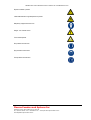
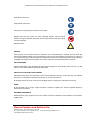
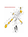
HIPOJET 2700M HIGH VELOCITY POWDER SPRAY GUN CAUTION Before using the equipment, read & understand this operating manual. In particular, refer to the Safety precautions. Under NO circumstances should any modifications be made to the equipment without prior written approval from PPS. OPERATION AND MAINTENANCE MANUAL FOR HIPOJET 2700 DISCLAIMER This document represents a collective effort involving a substantial number of volunteer specialists. Great care has been taken in the compilation and production of this document, but it should be made clear that no warranties, express or implied, including. Without limitation, warranties of merchantability or fitness for a particular purpose are given in connection with this document. Although this information is believed to be accurate by PPS.PPS cannot guarantee that favorable results will be obtained from the use of this document alone. This document is intended for use by persons having technical skill, at their sole discretion and risk. No claim of any kind, whether as to products or information in this document, and whether or not based on negligence, should be greater in amount than the purchase price of this product or publication in respect of which damages are claimed. The remedy here by provided should be the exclusive and sole remedy of buyer, and in no event should either party be liable for special, indirect, or consequently damages whether or not caused by or resulting from the negligence of such party. Nothing contained in this document should be construed as a grant of any right of manufacture, sale, use, or reproduction, in connection with any method, process, apparatus, product, composition, or system, and nothing contained in this document should be construed as a defense against any alleged. Plasma Powders and Systems Inc 228 Boundary Rd Marlboro NJ 07746 Ph: 732-431-0992 Fax : 732-308-1075 www.plasmapowders.com [email protected] OPERATION AND MAINTENANCE MANUAL FOR HIPOJET 2700 INTRODUCTION ABOUT THE MANUAL This user’s manual is intended to provide adequate information related to Metallizing gun HIPOJET 2700M to the reader. The information provided in this manual includes the installation, operation, maintenance information of above system. Failure to observe the information provided herein may result in risk to personnel health and safety, as well as damage to equipment. The document must be stored by a person charged to do so. Incase of loss or damage, replacement of documentation must be required directly to the PPS. Misuse or modification of this manual may result in personal injury. Do not misuse or modify. Plasma Powders and Systems Inc 228 Boundary Rd Marlboro NJ 07746 Ph: 732-431-0992 Fax : 732-308-1075 www.plasmapowders.com [email protected] OPERATION AND MAINTENANCE MANUAL FOR HIPOJET 2700 CONTENTS SR.NO. DESCRIPTION 1. 2. Safety measures Graphic symbol definition General Use of equipment Reduction of fire and explosion hazards Backfire Metal dust Gas cylinder precautions Eye Protection Introduction 3 Equipment description HIPOJET 2700 Gun Control panel Powder feeder Gas control unit and Air control unit Air Compressor Installation Unpacking Inspection Mounting of HIPOJET 2700 Gun Powder feeder Spray booth Check Operation Principle of operation Operating controls Hookup and initial adjustments Precautions Lighting Spraying Shutting down Construction and assembly Gas head Valve core positioning Gas siphon plug Exploded view of HIPOJET 2700M Part list of HIPOJET 2700M Tools and lubricants 4 5 6 Plasma Powders and Systems Inc 228 Boundary Rd Marlboro NJ 07746 Ph: 732-431-0992 Fax : 732-308-1075 www.plasmapowders.com [email protected] OPERATION AND MAINTENANCE MANUAL FOR HIPOJET 2700 7 Avoiding trouble Spraying General gun care Hoses Difficult lighting Backfire Siphon plug Nozzle assembly Gas head valve Overheating Lighting flow 8 HIPOJET hybrid Definition HIPOJET hybrid air cap assembly Gas requirement Recommended spare parts Installation of HIPOJET hybrid Spraying parameters SAFETY MEASURES GRAPHIC SYMBOL DEFINITIONS This manual uses a system of graphic symbols to alert the user to the presence of important operating instructions, safety consideration, and special instructions. These symbols (along with their definitions) are shown below: Additional information of general importance is provided Special instructions, safety instructions, etc. are being presented. Information, instructions, and restrictions necessary to prevent personal injury or damage to equipment are being presented. Plasma Powders and Systems Inc 228 Boundary Rd Marlboro NJ 07746 Ph: 732-431-0992 Fax : 732-308-1075 www.plasmapowders.com [email protected] OPERATION AND MAINTENANCE MANUAL FOR HIPOJET 2700 Explosive material is present Inflammable material or high temperature is present. Respiratory equipment must be worn. Danger : risk of electric shock Toxic material present Ear protection must be worn Eye protection must be worn Face protection must be worn Plasma Powders and Systems Inc 228 Boundary Rd Marlboro NJ 07746 Ph: 732-431-0992 Fax : 732-308-1075 www.plasmapowders.com [email protected] OPERATION AND MAINTENANCE MANUAL FOR HIPOJET 2700 Safety gloves must be worn Safety overalls must be worn Keep hands, hair, clothing and tools away from moving parts. Magnetic fields from high currents can affect pacemaker operation. Persons wearing electronic life support equipment (pacemaker) should consult with their doctor before going near spray equipment Radiation present GENERAL Flame spraying can be hazardous because it requires the use of combustible gases, containers and hoses under high pressure and potentially irritating or toxic spray materials. It may involve air contaminated by dust and mists, etc. However, it is a completely safe process when performed by a capable operator with proper understanding of flame spraying practices, knowledge of the equipment, care in operation, and one who follows the recommended precautionary measures. USE OF EQUIPMENT HIPOJET-2700M Flame Spray Equipment has been expressly designed for flame spraying. Never use it for any other purpose such as welding, soldering, and brazing and their like. REDUCTION OF FIRE & EXPLOSION HAZARDS Remember that the stream of sprayed metal is HOT. Point the lighted gun away from yourself and away from materials, which will burn. Carelessness in pointing the gun at paper or oily rags can result in fire. Be especially careful not to spray on the hoses, when lighting the gun. Hoses will burn. Keep them out of the way. GASES All gas equipment such as fuel gas, oxygen and airlines, compressors, regulators, etc. should be inspected regularly for leaks and loose connections. EQUIPMENT MAINTENANCE Maintain the flame spray equipment in first class condition. Follow the maintenance recommendations in the HIPOJET2700M manual. Plasma Powders and Systems Inc 228 Boundary Rd Marlboro NJ 07746 Ph: 732-431-0992 Fax : 732-308-1075 www.plasmapowders.com [email protected] OPERATION AND MAINTENANCE MANUAL FOR HIPOJET 2700 BACKFIRE Spray gun backfire can be prevented by proper maintenance. Inspect the gun and related equipment before starting to spray. Backfire may be caused by a leak at the nozzle, dirt in the nozzle, use of the wrong air cap etc. A gun will not backfire unless something is wrong. See the section on “Backfire” in the “Avoiding Trouble” Chapter in this instruction manual. METAL DUSTS All dust having considerable calorific value can be explosive. This dust includes: flour, starch, hard rubber dust, wool flour, Aluminium dust and the dust of other metals. Aluminium and magnesium dusts are particularly hazardous. The greatest care should be used in handling them. To minimize the danger of dust explosion resulting from flame spraying, adequate ventilation must be provided for spray booths and other confined spaces, to prevent the accumulation of fumes and dust. Good housekeeping in the work area is essential. Inspect and clean regularly to assure that there is no potentially dangerous accumulation of dust. Bag or filter type collectors are not suitable for metal spray dust. A water wash wet collector should be used. All of the dust must be wetted down and remain immersed in water. No accumulation of dry or partially wet dust should be permitted. A “PPS” Spray-booth is recommended. All closed collectors should be provided with blow out holes or relief panels. All fans, pipes, dust arresters and motors should be electrically grounded. GAS CYLINDER PRECAUTIONS Charged gas cylinders are potentially dangerous. Never put a gas cylinder in hazardous position. Keep cylinders away from heat and moisture. Always chain them to keep them from toppling. Put the valve caps on the cylinders when they are not connected for use. Do not hang a flame spray gun or its hoses on regulators or cylinder valves as a fire or explosion may result. REDUCTION OF RESPIRATORY HAZARDS Fumes or dusts of POWDERS can be toxic and hazardous. Efficient spray booth and exhaust system are therefore essential while spraying these. Besides, if the operator feels any discomfort a suitable mask with respiration facility may be used. REDUCTION OF NOISE HAZARD The operator and other personnel close to the flame spray operation should be protected from prolonged exposure to noise. If possible, the flame spray operation should be isolated. The noise level of HIPOJET-2700M ranges from 125 – 135 dBA. EYE PROTECTION Always wear eye protectors when operating, or watching the flame spray operation. Inspect the eye protectors frequently. Lenses and over plats, which are scratched, pitted or damaged, can impair vision and seriously reduce protection. Plasma Powders and Systems Inc 228 Boundary Rd Marlboro NJ 07746 Ph: 732-431-0992 Fax : 732-308-1075 www.plasmapowders.com [email protected] OPERATION AND MAINTENANCE MANUAL FOR HIPOJET 2700 REMINDER: SAFETY FIRST! Thermal spraying equipment is very powerful. Do not use equipment carelessly or without observing safe practices. Be safe! Learn the recommended procedures and standards. Failure to follow recommended procedures and standards can result in severe damage to equipment and injury to people. Use the equipment only if you have been trained fully in its safe operation. Do not allow untrained persons to install, operate, maintain, or troubleshoot the equipment. Make sure that you have read and understand the contents of this manual – especially the safety guidelines and operating procedures–before installing, operating or maintaining this equipment. Contact a Factory Representative if you do not fully understand any guidelines or instructions. CAUTION /WARNING Never keep fuel/fuel gas open while inspection /maintenance of parts during operating to check operational problems or parts inspection etc. This can cause entrance of fuel in oxygen /air line which may result explosion in oxyline/control panel. Plasma Powders and Systems Inc 228 Boundary Rd Marlboro NJ 07746 Ph: 732-431-0992 Fax : 732-308-1075 www.plasmapowders.com [email protected] OPERATION AND MAINTENANCE MANUAL FOR HIPOJET 2700 This manual contains specific precautionary statements relative to worker safety. Read thoroughly and comply as directed the use and application of this equipment with a MEC representative. Instruct all personnel’s on safe use and maintenance procedures. INTRODUCTION HIPOJET-2700M is a New Generation High Velocity Combustion Powder Spray gun, which provides supersonic spray velocities, combined with improved heating and melting of the powder particles. Seven Shock Diamonds characteristic of a supersonic flame are visible in the flame. The high velocity technique has great opportunities where near porosity free high quality coatings at the most economical cost is the requirement. This is a low cost affordable HVOF System, which produces premium quality coatings. HIPOJET-2700M coatings are similar to or comparable to other High Velocity Spraying Process in term of Lower Porosity High Hardness High Bond Strength Excellent Wear Resistance Good Surface Finish - as sprayed Thick Coatings (if required) Fine Finishing Capability The operating cost of High Velocity combustion powder spray is lowest, compared to other HVOF & Plasma Spray Technique with quality results. The equipment is very easy to use. This manual is intended to serve as a guide for the installation, operation & maintenance of the HIPOJET-2700M System. After getting conversant, the user will normally encounter no difficulty in the operation of the HIPOJET-2700M System. In case of any special problems, however, he is most welcome to refer those to the manufacture Plasma Powders and Systems Inc. who will be to glad to help / solve the problems in the least possible time. Plasma Powders and Systems Inc 228 Boundary Rd Marlboro NJ 07746 Ph: 732-431-0992 Fax : 732-308-1075 www.plasmapowders.com [email protected] OPERATION AND MAINTENANCE MANUAL FOR HIPOJET 2700 EQUIPMENT DESCRIPTION A complete flame spray installation requires equipment to supply and control compressed air, oxygen, fuel gas and Metallizing powder. The HIPOJET-2700M Metallizing System consists of the following main parts: 1. 2. 3. 4. 5. 6. 7. The HIPOJET-2700M Gun The Control Panel The Powder Feeder; PF-700/ PF-3350 The Gas Vaporizer The Hose Kit The Gas Control Unit & Air Control Unit. Air compressor HIPOJET-2700M GUN The Spray Gun has been designed and built to be one of the world’s best hand guns for producing supersonic spray velocities, in flame sprayed coatings with Powders. The standard gun is set up to spray HVOF Grade Powders using Liquefied Petroleum Gas (LPG), propane, Propylene or Natural Gas as the fuel gas. Suitable hardware is available for LVOF spraying using D.A. as fuel gas. CONTROL PANEL The PPS Control Panel Model is the most important and heart of the HIPOJET-2700M HVOF Powder Spray System. It’s precious equipment used for regulating and measuring the flow of oxygen, fuel gas and air to High Velocity Oxy-Fuel Powder flame Spray Gun. Connected between the gas supply and the gun, it is the reliable indicator of gas flow and aid to highest coating quality. POWDER FEEDER; PF-700/ PF-3350 Powder Feeder; PF-700/PF-3350 is specifically designed for thermal spray applications. This is one of the most accurate powder feeders. The powder is filled in the powder container, which is pressurized by the carrier gas. The powder is filled in the slots of the powder wheel, which is rotating at a pre-determined rpm. The powder wheel delivers the powder from the slots to the powder feed hose where the carrier gas carries the powder to the Spray Gun. Varying the rpm of the variable speed AC motor controls the powder feed rate. (For details please refer the instruction manual of powder feeder. GAS VAPORIZER For smooth and continuous operation of HVOF system, PPS offers a Gas Vaporizer unit. Using LPG as a fuel gas, there is a continuous occurrence of liquid in the gas flame due to high pressure and flow require in the HVOF spraying. This necessitates the use of a gas vaporizer for a smooth, trouble free operation. HOSE KIT This is a group of three-matched high pressure, high quality, lightweight flexible hoses equipped with proper fittings for HIPOJET-2700M Gun. It consists of a black air hose and a dual hose for gases, green or blue for oxygen and red for fuel gas. The hoses have proper fittings to connect to the control panel at one end and to the gun at the other. The control panel end should be connected first and the hoses blown out at low pressure before the gun is connected. Plasma Powders and Systems Inc 228 Boundary Rd Marlboro NJ 07746 Ph: 732-431-0992 Fax : 732-308-1075 www.plasmapowders.com [email protected] OPERATION AND MAINTENANCE MANUAL FOR HIPOJET 2700 GAS CONTROL UNIT & AIR CONTROL UNIT This unit includes precision two-stage regulators for accurate adjustment of oxygen and fuel gas pressures where continuous, high speed spraying will be done. Manifolding is recommended for connecting several gas cylinders together. The Air Control Unit has two filters for removing oil and moisture from the compressed air and a pressure regulator for regulating the air pressure. AIR COMPRESSOR A minimum of 51m3/hr of free air delivery is required at 6 Kg/Cm2 (90 psig). Taking into consideration the pressure in the piping, connections and regulator, the line pressure of at least 7.0Kg/Cm 2 (105 psig) at the regulator should be provided during spraying. Plasma Powders and Systems Inc 228 Boundary Rd Marlboro NJ 07746 Ph: 732-431-0992 Fax : 732-308-1075 www.plasmapowders.com [email protected] OPERATION AND MAINTENANCE MANUAL FOR HIPOJET 2700 INSTALLATION Unpacking Remove all packing material and part containers from the carton box(s) and make sure that right parcel has been sent. Inspect unit on delivery. Report any damage to the delivery carrier. Compare unit received with description of product ordered. Report incomplete shipments to the delivery carrier and to PPS representative. Remove crates and shipping straps. Remove loose components and accessory packages before lifting unit. Installation codes Safe and efficient operation of the unit depends on proper installation. A qualified installation and service engineer must complete installation and service of this equipment. All shipping materials, including shipping covers, must be removed from the unit prior to or during unit installation. Locate the collector to ensure the shortest and straightest inlet-and outlet–duct length, easy access to electrical and compressed–air connections, and routine maintenance. Mount the HIPOJET-2700M Gun in Position for use. The control panel, powder feeder PF-700/ PF-3350, gas and air control units must be mounted within reach of the gun hoses / cables. The fuel gas and oxygen cylinders, should always be strapped or chained to the wall to prevent their being knocked over. Always blow out the gas cylinder valves before attaching the regulators. Always back out the pressure regulating screws before opening cylinder valves. Open the cylinder valves slowly. Do not let regulators stand under pressure when not in use. Failure to observe these precautions may result in damage to the regulators. POWDER FEEDER (PF-700/ PF-3350) Place the Powder Feeder; PF-700/ PF-3350 within reach of the HIPOJET-2700M gun. The powder feed tube and carrier gas hose connection and electric cable connection should be made as suitable. To get good quality coatings, nitrogen / argon should be used as carrier gas instead of air. Set the powder feed rate of the powder as per the parameter sheet of the powder. (Please see details of set up of the powder feed rate in the powder feeder; PF-700/ PF-3350 manual.) SPRAY BOOTH Metal dust, fumes and the fuel combustion products call for an effective exhaust and dust collection system. In production installations, if the spraying station is enclosed, make sure that there is enough opening for inlet air so that the exhaust system is not starved. Under some conditions, metal dusts can be quite hazardous. For this reason, it is advisable to install a spray booth, especially designed for metal spraying. Dust collectors designed primarily for other kinds of dust may be found to be very ineffective and, in some cases, dangerous, if used for metal dust. CHECK Good shop practice and sound engineering require that the installation be checked before it is put into operation. Check the power line voltage connections, the fuel gas, oxygen and air connections, and the installation of the exhaust system before turning on a valve or throwing a switch for the first time. Plasma Powders and Systems Inc 228 Boundary Rd Marlboro NJ 07746 Ph: 732-431-0992 Fax : 732-308-1075 www.plasmapowders.com [email protected] OPERATION AND MAINTENANCE MANUAL FOR HIPOJET 2700 OPERATION PRINCIPLE OF OPERATION The powder is fed through the gun into a fuel gas & oxygen flame. A stream of compressed air restricts the flame and blasts the molten powder, producing a fine spray and obtaining high or supersonic particle velocity. The compressed air also does the job of cooling the nozzle air cap assembly. Many outstanding design features are offered by the HIPOJET-2700M Gun. Some of these are described below: 1. 2. 3. 4. 5. The newly developed improved version of HIPOJET-2700M gas head produces supersonic velocity of particles. The improved version of HIPOJET-2700M-siphon plug - nozzle assembly produces high heat flame and supersonic velocity of atomized particles. A powder feeder; PF-700/ PF-3350 is developed for getting consistent powder feeding. A control panel for easy to read out parameters and safe, easy and leak free operation. A Gas Vaporizer for smooth and continuous spraying without the interference of liquid in the flame. OPERATING CONTROLS There is only one operating control on the gun i.e. "Gas Head Valve Core: The gas head valve controls the flow of gases and air to the gas head. Each gun is given an operating test before leaving the factory and is ready to be hooked up when received. If several months have elapsed between the time the gun is received and is first put into service, it may be necessary to re-lubricate the valve for the unit to operate smoothly. When putting the gun into operation 1. Use the nozzle and air cap shown in the part list. 2. The nozzle sleeve must be firmly seated inside the nozzle. Make sure that the mating surfaces are clean and free of chips. 3. Make sure that the nozzle nut is tight. Tightening by hand is sufficient. 4. The siphon plug flange must be firmly seated against the gas head. Make sure that the mating surfaces are clean and free of chips. 5. The air cap body must be on tight. Tightening by hand is sufficient. 6. Check the gas head valve for smooth, easy action. Re-lubricate if necessary. HOOKUP AND INITIAL ADJUSTMENTS Connect the hoses to the control panel and air & gas control units. Blow out the hoses, powder tube and then connect to the gun. Air and oxygen hoses must have right hand threads and the fuel gas hose has a left hand thread. The hose nuts must be drawn up tight enough to prevent leakage but should not be over tightened as this may crush the hose stem. Point the gun into the spray booth or towards the job. Open the gas head valve by turning the valve handle straight up and adjust the air pressure at the regulator until the gauge shows the pressure specified in the high velocity parameters or spraying table. If the valve is now turned off (horizontal) the pressure gauge should not show more than 0.7 Kg/Cm2 (10 psig) increase. A greater pressure rise usually indicates regulator trouble or a restriction upstream from the air control unit. In either case the trouble should be corrected before proceeding. Turn the valve handle up at 45 degrees until it clicks. This is the LIGHTING POSITION. Turn the valve handle all the way up and a strong blast of air will come out of the air cap. This is the RUNNING POSITION. After connecting the powder feeder and the gas hoses to the gun, the HIPOJET system is now ready for operation. Plasma Powders and Systems Inc 228 Boundary Rd Marlboro NJ 07746 Ph: 732-431-0992 Fax : 732-308-1075 www.plasmapowders.com [email protected] OPERATION AND MAINTENANCE MANUAL FOR HIPOJET 2700 Precautions: 1. The carrier gas must be in the ON position before lighting the gun and the carrier gas flow meter should be set for the reading of 10 before lighting the gun. 2. Check the nozzle sleeve before start up for its I.D. The standard I.D. is 1 mm. The ID should in no case increase over 1.2 mm. Failure to follow the above precautions may lead to back fire and damage the equipment and/or injury to operator. Adjust the powder feed control knob (rpm controller on the powder feeder) to obtain the desired feed rate of the powder as per the parameter sheet supplied. With the gas head valve open, quickly set the oxygen and fuel gas pressures to the figures shown in the spraying table under NORMAL LIGHTING FLOW. Adjust the control panel flow-meter with the help of the flow values shown in the table. Then close the gas head valve. LIGHTING CAUTION: Be sure that the compressed air is present inside the gas head. The carrier gas must be in the ON position. Ball valve position must be closed. When you are ready to start spraying: When starting for the first time, set the reading of carrier gas flow in carrier gas flow-meter of the powder feeder at 25. Shut off the ball valve on the gun to prevent the carrier to escape and pressurize the powder canister. Take up the gas lighter and open the gas head valve all the way (straight up). Pause about three seconds. Close the valve halfway until you feel it click into the lighting stop. Spark the lighter in front of the nozzle. Immediately open the valve all the way as soon as the gun lights. After lighting the gun, check the pressure in the powder canister. It should be more than 3 bar (44 psi). Now open the ball valve for the carrier gas to flow through the gun. There is no need for a new operator to hurry the several motions required except that the valve must be opened completely immediately after lighting. NOTE: For supersonic spraying, use only LPG or propane as a fuel gas. After the gun is lighted: 1. 2. After opening the Ball Valve, wait for a few seconds for the pressure to stabilize in the powder canister and then push ON the powder feed button to start the powder. (If the powder feed is started very early, the nozzle may choke with powder OR irregular flow of powder may be observed for some time). Re adjust the carrier gas flow between 10-15 units in the flowmeter. This setting should not be disturbed even if the gun is stopped and started again. This setting is only changed if the powder is changed or coating parameters are changed. Plasma Powders and Systems Inc 228 Boundary Rd Marlboro NJ 07746 Ph: 732-431-0992 Fax : 732-308-1075 www.plasmapowders.com [email protected] OPERATION AND MAINTENANCE MANUAL FOR HIPOJET 2700 3. 4. Set the powder feed rpm to obtain the feed rate as specified in parameter of the powder. Readjust the fuel gas and oxygen regulators until the reading on the gas flow meter correspond to the Spraying Table is achieved. SPRAYING The gun should be held from 12.5cm to 20cm away from the surface being sprayed. For small work, such as shafts less than 2.5cm in diameter, it is advisable to cool the work with air blast. For information on surface preparation and for general information on application of the thermal spray process, refer to the handbook. SHUTTING DOWN To shut the gun down, turn off the gas head valve and push OFF the Powder Feed Button and close the ball valve. If the gun will not be used again for several hours shut off the oxygen and fuel gas at the cylinders and shut off the air at the regulator on the air control unit. It is also good practice to back out the pressure regulating screws on the gas pressure regulators and bleed off pressure in the hoses and gun by opening the gas head valve momentarily. DIFFERENT GASES HIPOJET-2700M Gun is equipped with a universal gas head. It may be used with oxygen and combustible gas such as Propane, Propylene, and Liquefied Petroleum Gas (LPG). Suitable hardware is available to use acetylene as the fuel gas. Use acetylene only for conventional low velocity flame spraying. NOZZLES There are two types of powder nozzles, propane (or LPG) and Acetylene (for low velocity spraying). The nozzles for acetylene are flat on the small end. The propane nozzle is counter bored on the small end. SIPHON PLUGS There are two different siphon plugs, according to fuel gas as L.P.G. or Acetylene. For using Acetylene as the fuel gas, see note in the part list. Plasma Powders and Systems Inc 228 Boundary Rd Marlboro NJ 07746 Ph: 732-431-0992 Fax : 732-308-1075 www.plasmapowders.com [email protected] OPERATION AND MAINTENANCE MANUAL FOR HIPOJET 2700 CONSTRUCTION & ASSEMBLY GAS HEAD The gas head consists of air cap, siphon plug, nozzle and “O” rings which is fastened to the main body of the gun. A cylindrical valve core (HP-2743), centrally located in the gas head is held in place of both the valve handle (HP-2745) and screw (HP-179), which holds hose connection block (HP-176) to the bottom of the gas head. To disassemble the valve for cleaning and lubrication: 1. 2. Clean the outside of the valve thoroughly to remove dirt and grit. Remove the valve handle and hose connection block. Lighting Detent Pin (HP-173) and spring (HP-174), trapped by the valve handle, can now be removed. “O” Rings (HP-44), in grooves on the hose connection block, can be lifted out. These seal against leakage at the mounting face. Remove plunger springs (HP-171). Remove two plungers (HP-165) and one plunger (HP-166) by pulling on the plunger stem. Do not twist. Each plunger is keyed against rotation. Slide valve core (HP-2743) out of the gas head. Never try to take out the valve core before removing the hose connection block. Four “O” rings (HP-44) and one “O” ring (HP-14) on the valve core seal off the oxygen, fuel gas and air from each other and from leakage to the outside. Two plunger seal “O” rings (HP-170) and one plunger seal “O” ring (HP-169), normally squeezed against the valve core by the front ends of the spring loaded plungers, and may stick to the plunger when the plungers are removed. If not, these rings will be found in the gas head holes, which house the plungers. Push these rings into the valve bore and take them out for servicing. 3. 4. 5. 6. Before reassembling the valve parts 1. 2. 3. Examine all “O” rings and replace those which are worn or damaged. Use only authorized replacements. If cleaning is needed, use a clean cloth slightly dampened with cleaning solvent. Never soak the “O” rings in solvent or any other liquid. Wash the metal parts with cleaning solvent as required. Full-flow and bleeder ports are machined into the valve core for proper control of the gases. These ports should be clean and free of any hard residue. Lubricate valve “O” rings and sliding metal parts with a thin coat of valve lube. When putting back the plungers, align the plunger keyway with the mating key pin in the gas head. Slide each plunger into its hole and press firmly all the way home to seat each seal ring against the valve core. When properly installed, the large diameter of each plunger will be completely inside its hole. If it is not, it means that the key pin is not engaging the plunger keyway and the valve will not seal properly. A dowel pin in the hose connection block fits into a mating hole at the bottom of the gas head to preserve proper orientation. The long nose on the connection block mounting screw (HP-179) (next to air hose fitting) engages a groove in the valve core. Make sure to put this screw back in its proper place. Check that the connection block “O” rings are in their retaining grooves before tightening the connection block screws. VALVE CORE POSITIONING One end of the valve core has an aluminum knob. With the valve core in place in the gas head, before, mounting the valve handle, turn the core so that a hole appears pointing towards the back of the gas head. Point the valve handle forward and Plasma Powders and Systems Inc 228 Boundary Rd Marlboro NJ 07746 Ph: 732-431-0992 Fax : 732-308-1075 www.plasmapowders.com [email protected] OPERATION AND MAINTENANCE MANUAL FOR HIPOJET 2700 screw it on to the stem of the valve core. When properly mounted, the head of the valve handle screw will be in line with the hole of the valve core. If they are opposite instead of in line, the valve will not feed air to the gas head when you try to spray. GAS SIPHON PLUG The gas siphon plug (HP-2) fits into the large hole through the upper part of the gas head. The flange of the siphon plug has two slots, which mate with two pins in the head. Four “O” rings (HP-14) seal against gas leakage. The powder injector (HP-2723) threads into the back of the siphon plug. Nozzle sleeve fitted inside the nozzle (HP-7A) and is held on to the front of the siphon plug by nozzle nut (HP-2706). Air cap (HP-3) slips into the front recess of the nozzle nut and air cap body (HP-2701) holds this entire assembly in place of the head. With the air cap body off, the entire assembly of siphon plug, nozzle, nozzle nut and air cap can be quickly removed. Whenever the siphon plug is removed, examine the “O” rings for nick and cuts. If they are damaged, replace them. When reinstalling the siphon plug, lubricate the “O” rings with valvelube. Make sure that the slots in the siphon plug flange engage the two gas head pins. The powder injector must be threaded into the siphon plug, as it will go. Push the siphon plug assembly in until the flange of the siphon plug is firmly seated against the gas head with the two dowels. Air cap body (HP-2701) must be on tight before spraying. Plasma Powders and Systems Inc 228 Boundary Rd Marlboro NJ 07746 Ph: 732-431-0992 Fax : 732-308-1075 www.plasmapowders.com [email protected] PART LIST OF HIPOJET 2700M PART NO. HP-2701 DESCRIPTION AIR CAP BODY HP-03A AIR CAP HP-03B AIR CAP HP-03C AIR CAP HP-2706 NOZZLE NUT HP-108 NOZZLE “O” RING HP-7A NOZZLE HP-109 NOZZLE “O”RING HP-02 SIPHON PLUG HP-14 SIPHON PLUG “O” RINGS HP-174 DETENT PIN SPRING HP-2745 VALVE HANDLE HP-31 VALVE HANDLE SCREW HP-173 DETENT PIN HP-2742 MAIN BODY HP-2723 POWDER INJECTOR HP-2718 BALL VALVE HP-157 HOSE CONNECTION BLOCK MOUNTNG SCREW HP-179 VALVE CORE STOP SCREW MDJ-176 HOSE CONNECTION BLOCK HP-44 HOSE CONNECTION BLOCK “O” RINGS HP-165 PLUNGER(FUEL GAS & OXYGEN) HP-166 PLUNGER(AIR) HP-167 PLUNGER “O” RING (AIR) HP-168 PLUNGER “O” RING(FUEL GAS & OXYGEN) HP-169 PLUNGER SEAL “O” RING (AIR) HP-170 PLUNGER SEAL “O” RING(FUEL GAS & OXYGEN) HP-14 SIPHON PLUG “O” RINGS HP-2743 VALVE CORE HP-2714 GUN MOUNTING PLATE HP-2715 GUN MONTING SUD HP-2716 GUN MONTING PLATE SCREW HP-28 GUN HANDLE SCREW HP-31 VALVE HANDLE SCREW HP-301 HANDLE HP-2745 VALVE HANDLE TOOLS & LUBRICANTS PART. No. DESCRIPTION HP-101 LIGHTER HP-104 SPANNER WRENCH (13-17) HP-105 SCREW DRIVER HP-111 VALVE LUBE HP-114 CLEANING WIRE KIT HP-111 HP-104 HP-164 HP-114 HP-115 HP-105 HP-101 OPERATION AND MAINTENANCE MANUAL FOR HIPOJET 2700M AVOIDING TROUBLE SPRAYING Refer to “Safety Measures” for a summary of common sense precautions to be observed when flame spraying. GENERAL GUN CARE The most important point in the case & lubrication of HIPOJET-2700M Gun is cleanliness. Before lubrication, wipe the gun thoroughly to remove all loose dust. Use a clean bench for disassembly and be sure that the lubricant tube is free of dirt. There is a chart showing a suggested maintenance schedule at the end of this chapter. This chart is based on average use and conditions. Guns receiving hard use should be serviced at shortest intervals. The main factors affecting service frequency are: 1. 2. Frequency of lighting Temperature at which the gun operates. HOSES Obstruction in the hoses reduces the flow of oxygen and gas and upset the flame balance. Do not let oil in the hoses. Oil in the oxygen hose is very dangerous. In any hose, oil will soften the rubber. In an old, worn hose the lining may come loose and plug the hose. If hose fittings are over-tightened, the holes in the fittings may collapse. This reduces the flow of gases and causes the same troubles as obstructions in the hoses. NOTE: Use only High Pressure Hoses. DIFFICULT LIGHTING If the gun is hard to light, make sure that the nozzle and siphon plug jets are clean and undamaged. If the trouble persists, screw out the regulator handles to shut off the gases and then disconnect the hoses. Inspect hoses and gun fittings for dirt or other obstruction. Blow out the hoses before reconnecting them. If the gun has been idle for some time or after the valve has just been lubricated, it is advisable, before lighting, to work the valve on and off a few times with gases and air turned on. This will blow out any excess valve lubricant from the small bleeder holes in the valve. Plugged bleeder holes will cause lighting trouble. The carrier gas should be in the ON position before lighting & the POWDER FEEDER (PF-700/PF-3350) flow-meter should show a reading of 15 before lighting. The nozzle sleeve ID should not be more than 1.2 mm Plasma Powders and Systems Inc 228 Boundary Rd Marlboro NJ 07746 Ph: 732-431-0992 Fax : 732-308-1075 www.plasmapowders.com [email protected] OPERATION AND MAINTENANCE MANUAL FOR HIPOJET 2700M BACKFIRE If the gun backfires, it will appear to go out with a “pop” and will burn back in the siphon plug. Shut OFF the gun immediately and wait for about thirty seconds before re-lighting. The following may cause backfire: 1. 2. 3. 4. 5. 6. 7. 8. 9. 10. Leak at the powder nozzle seat (see powder nozzle) Dirt in the nozzle jets. Oversized or ragged nozzle jet holes. Plugged siphon plug bleeder holes (see siphon plug). Use of wrong air cap. Unbalanced oxygen and fuel gas ratio Oversized of nozzle insert (I.D. more than 1.2 mm) Use of wrong nozzle, nozzle sleeves and siphon plug. Carrier gas flow is not ON. Carrier gas flow should not be increased to 20 - 25 immediately after lighting. It is possible for a single jet to backfire and the others to operate normally. The flame will suddenly become slightly onesided. Correction must be made immediately to prevent overheating of the siphon plug and gas head. Replacing the nozzle and cleaning the siphon plug is the best and most economical solution. Excessive backfire or permitting the gas to burn back in the siphon plug too long makes it necessary to clean the jets in the siphon plug and nozzle. It may also cause the nozzle nut to loosen. The cause of the backfire should be found and corrected. The gun will not backfire unless something is definitely out of adjustment. SIPHON PLUG This part should be cleaned occasionally. Instructions for removing and replacing it are given in the section on “Construction and Assembly”. When cleaning it, wipe out the grooves. Clean the jets with the proper size wire in the cleaning wire kit. Do not use drills. Do not use oversized wires. Do not rotate the wires. There are two small air bleeder holes in the siphon plug just back of the nozzle seat. These holes permit air to circulate around the powder tube injector. If they plug up, the powder nozzle may overheat, causing backfire or sticking powder. When serving the siphon plug, be sure to clean these bleeder holes with the proper size cleaning wire. Do not wash the “O” Rings with strong solvent. Inspect them for damage and replace them if necessary. Do not stretch new “O” rings more than necessary when putting them on the siphon plug. Lubricate the “O” rings with a generous film of valvelube before reassembling the siphon plug. Wipe any excess valve lube off the plug to avoid getting it in the jets. NOZZLE ASSEMBLY The nozzle assembly consists of two main parts: 1. 2. Nozzle Nozzle Sleeve The tip of the nozzle should be kept clean. To clean the nozzle, remove the nozzle insert from the nozzle assembly. Wash both insert and nozzle in cleaning solvent. Do not soak O-Rings in solvent. Inspect them for damage and replace them, if necessary. Do not over stretch the new O-Rings when putting them on the nozzle. Lubricate O-Ring with a thin film of valvelube. To clean the jet holes, push the proper size cleaning wire, carefully into each jet hole. Do not use a drill. Select a wire that fits the hole. Do not rotate it. Using compressed air, blow out the jet holes from back end. Push nozzle sleeve into the nozzle. Plasma Powders and Systems Inc 228 Boundary Rd Marlboro NJ 07746 Ph: 732-431-0992 Fax : 732-308-1075 www.plasmapowders.com [email protected] OPERATION AND MAINTENANCE MANUAL FOR HIPOJET 2700M The nozzle sleeve fits inside the nozzle and it is a critical component for feeding powder to the gun. The sleeve is supplied with an I.D. of 1 mm. The I.D. of sleeve should not in any case be more than 1.2 mm. This may happen due to wear of the nozzle sleeve. Replace the nozzle sleeve, if I.D. is observed to be over 1.2 mm GAS HEAD VALVE The gas head valve is designed for long service life with minimum maintenance. It has a cylindrical rather than the old-style tapered core and relies upon special electrometric “O” rings for proper sealing. Lapping or other precise fitting is not required. Do not disassemble the valve for cleaning and re-lubricating, unless it has become excessively stiff and difficult to turn or a leak has developed. Instructions for taking it apart are given in “Construction and Assembly”. If the valve develops a leak, examine all “O” rings carefully and replace any which are worn or damaged. The ring materials are specially selected for proper service in this valve. Use only authorized replacements. The metal parts of the valve can be washed with cleaning solvent. Make sure that the small bleeder holes in the cylindrical valve core are clean and free of any hard residue. Do not enlarge them. Never soak the “O” ring in solvent. Lubricate all valve “O” rings and sliding metal parts with a thin coat of valvelube. Wipe excess valvelube off the nozzle, to avoid getting it in the jet holes. POWDER FEEDER PF-700/PF-3350 The powder feeder requires 220V, 50Hz single phase OR 220 V / 3 P power supply. Powder feed control knob (rpm controller) controls the powder feed rate and LCD display box display the powder feed rate in rpm. If the powder feed becomes unstable or feed rpm is not displaying, check powder feed ON / OFF button, electric cables, and power supply. NOTE: After switching “OFF” from the powder feeder, wait for 10 sec before restarting. OVERHEATING The increased spraying speed of the Gun is the result of greatly increased heating capacity. Be sure to observe the recommended procedures to prevent overheating of the work or damage of the coating. LIGHTING FLOW Normal gas flow ranges with the gas head valve in the lighting position are given below. Plasma Powders and Systems Inc 228 Boundary Rd Marlboro NJ 07746 Ph: 732-431-0992 Fax : 732-308-1075 www.plasmapowders.com [email protected] OPERATION AND MAINTENANCE MANUAL FOR HIPOJET 2700M NORMAL LIGHTING FLOW Oxygen Fuel Gas Air 8 6 5.5 250+ 60 550 Pressure (Kg/Cm2) Flow (SLPM) CAUTION: Use only standard replacement parts of HIPOJET-2700M. ROUTINE MAINTENANCE SCHEDULE BASED ON CONTINUOUS SPRAYING Maintenance Operation Clean nozzle sleeve & check ID : AVERAGE CONDITIONS Interval Remarks Before operation If bore size is more than 1.2 mm, replace sleeve Clean outside of the Gun 8 Hrs. Clean air cap 8 Hrs. Wipe out soot. Clean nozzle jets 16 Hrs. Use nozzle cleaning wire kit. Clean siphon plug jets and bleeder holes 40 Hrs. Use nozzle cleaning wire kit. Clean and lube gas head valve 500 Hrs. Valvelube thin film. Plasma Powders and Systems Inc 228 Boundary Rd Marlboro NJ 07746 Ph: 732-431-0992 Fax : 732-308-1075 www.plasmapowders.com [email protected] OPERATION AND MAINTENANCE MANUAL FOR HIPOJET 2700M HIPOJET HYBRID DEFINITION The HIPOJET HYBRID is an advanced HVOF coating system used to produce coatings for highly demanding applications. The premium quality coatings are achieved by the air cap of the spray torch, which achieves gas velocity of nearly 7000 ft/sec. This high gas velocity is translated into high particle velocities, which results in extremely dense, hard and well bonded coatings. The coatings of HIPOJET HYBRID are a quantum improvement over the HIPOJET coatings. The HIPOJET HYBRID uses less cooling water than any other commercially available HVOF system. Water usage is only 2 gallons per minute (9.5 l/m). This is due to the specially designed hardware. The combustion chamber behind the air cap is air-cooled and the air cap itself is water-cooled. This greatly minimizes the amount of water-cooling required, and increases the thermal efficiency of the gun. The spray particles contact with the air cap walls is minimum. Thus increases the air cap life. The air cap typically has a usable life exceeding 40 hours. The air cap passages are designed to eliminate backfire in HIPOJET. This greatly increases the reliability of the gun and makes the HIPOJET the best choice for coatings requiring reproducible results. HIPOJET HYBRID AIR CAP ASSEMBLY The HIPOJET Torch uses an elongated air cap, which is water-cooled. The air cap assembly fits on the HIPOJET Gun. The elongated air cap produces higher particle velocity than that of the standard HIPOJET Gun. The cooling water requirement of the HIPOJET can be fulfilled by city water. There is no requirement of a booster pump if the water supply pressure is above 40 psi. The HIPOJET HYBRID air cap assembly is designed to use propylene or propane as fuel gas. The HIPOJET HYBRID produces the lowest cost HVOF coatings in the industry. GAS REQUIREMENTS The following is a list of the types of gases and their purpose, used by the HIPOJET HYBRID. Nitrogen Used as a carrier gas for feeding the powder through the gun. Consumption is approximately 50 SCFH (22 SLPM) at 175 psi (12.1 bar). Oxygen Used to mix with the fuel gas. Consumption is approximately 750 SCFH (438 SLPM) at 200 psi (11 bar). Propane / LPG Used as a fuel gas. Consumption is approximately 350 SCFH (87.6 SLPM) at 125 psi (8 bar) Air Used to cool torch and increase velocity. Consumption is approximately 1200 SCFH (526 SLPM) at 120 psi (8.3 bar) RECOMMENDED SPARE PARTS Part No. Description HY-1 Locking Cap HY-2 Cooling Distributor HY-3 O-Ring Plasma Powders and Systems Inc 228 Boundary Rd Marlboro NJ 07746 Ph: 732-431-0992 Fax : 732-308-1075 www.plasmapowders.com [email protected] OPERATION AND MAINTENANCE MANUAL FOR HIPOJET 2700M HY-4 Water Adapter HY-5 Connector (Inlet / Outlet) HY-6 O-Ring HY-7 O-Ring HY-8 Air Cap Body HY-9 O-Ring HY-10 Long Air Cap (9.5 mm dia) INSTALLATION OF HIPOJET HYBRID Follow the instructions given below to install the HIPOJET HYBRID on the HIPOJET-2700M Gun. 01. Remove the air cap body (HY-1) from the HIPOJET-2700M Gun 02. Remove the O-ring (HY-3) from the HIPOJET-2700M Gun The HYBRID is supplied fully assembled to install it on the HIPOJET Gun, first follow these steps. 03. Open the locking cap (HY-1) from the HYBRID assembly. 04. Open the water adapter (HY-4) by a pulling and twisting action taking care not to damage the O-rings on the air cap body (HY-8). SAFETY: Inspect the O-Rings on the air cap body for any damage before refitting of the water adapter. The HIPOJET-2700M is now ready to accept the HIPOJET HYBRID ASSEMBLY. Follow instructions given below: 05. The HYBRID ASSY now consists of cooling distributor (HY-7) and air cap body (HY-8). Hand tighten the HYBRID assembly on the HIPOJET gun with the threads on the air cap body (HY-10) of HYBRID and the HIPOJET Gun. 06. Press the air cap with the thumb. If the air cap remains fixed i.e. it does not go inside then the tightening of the air cap assembly is OK. If the air cap (HY-10) moves inside, some tightening of the air cap (HY-10) assembly is required. 07. Slide the water adapter (HY-4) by twisting and pushing action taking care not to damage the O-Rings on the air cap body. Push it till it does not go any further as it will rest on the collar present on the air cap body. SAFETY: Inspect the O-Rings on the air cap body for any damage before refitting of the water adapter. 08. Tighten the locking cap (HY-1) on the HYBRID Assy. 09. Connect the water inlet and outlet as marked on the HYBRID Assy. 10. Supply water at 40 psi or above to the (max 150 psi) HYBRID Assembly and check for leakage if any. Plasma Powders and Systems Inc 228 Boundary Rd Marlboro NJ 07746 Ph: 732-431-0992 Fax : 732-308-1075 www.plasmapowders.com [email protected] OPERATION AND MAINTENANCE MANUAL FOR HIPOJET 2700M NOTE: If water leakage is there, check the O-Rings on the air cap & air cap body (HY-8) for damage. Replace the damaged O-Rings. INSTRUCTION FOR CHANGING O-RINGS ON AIR CAP (HY-10) AND AIR CAP BODY (HY-8) 01. 02. 03. Open the locking cap (HY-1) and water adapter (HY-4). This will expose the O-rings (HY-6, & HY-7). Inspect them for any damage and replace damaged O-Rings. To inspect the O-Rings (HY-9) on the air cap, remove the HYBRID assembly from the HIPOJET Gun. Now push the air cap from the front. The air cap will come out from behind. Remove the air cap and inspect the ORing (HY-9), if O-Ring is damaged, replace the same. NOTE: While replacing any O-Ring, lubricate the same with valve lube. 04. Insert the air cap (HY-10) back into the air cap body (HY-8). 05. Follow the instructions from 05 to 10 of installation of HIPOJET HYBRID to install HYBRID ASSY. Plasma Powders and Systems Inc 228 Boundary Rd Marlboro NJ 07746 Ph: 732-431-0992 Fax : 732-308-1075 www.plasmapowders.com [email protected] SPRAYING PARAMETERS The parameters for HIPOJET-2700M Spraying using the PPS Control Panel are given below: SPRAY PARAMETERS: 1. PF-700 Powder Feeder 2. LPG Fuel Gas 3. Control Panel Fuel Pressure : 6 Kg / Cm2 Oxygen Pressure : 8 Kg / Cm2 Air Pressure : 5 Kg / Cm2 Fuel Flow* : 60 LPM Oxygen Flow : 250 LPM Carrier Gas Pressure : 5 Kg / Cm2 Carrier Gas Flow-meter Reading : * 10 - 15 ( ~20 SCFH) LPG liquefies during spraying and this liquid interferes with the flow-meter reading and we do not get accurate reading for fuel gas. In order to stop liquid interference, use PPS gas vaporizer. Spray Distance should be maintained as 6" - 8" The table below gives the Powder Feeder (PF-700) settings for various powders: Powder Metco Diamalloy WC-Co12% 2004 WC-Co17% Spray Rate rpm 5.38 gm/cc 38 gm/min. 3.00 2006 ------ 38 gm/min. 3.00 CrC-NiCr25 3004 2.39 gm/cc 38 gm/min. 6.74 Inconel 625 1005 4.65 gm/cc 60.5 gm/min. 5.51 Inconel 718 1006 4.45 gm/cc 60.5 gm/min. 5.76 Fusible Nickel Base Alloy Powder 2001 4.25 gm/cc 38 gm/min. 3.79 Stainless Steel316 (Iron-Cr17-Ni13) 1003 4.43 gm/cc 45 gm/min. 4.28 Note: Above No. Density parameters are guidance only. OPERATION AND MAINTENANCE MANUAL FOR HIPOJET 2700M This publication could include technical inaccuracies or typographical errors. Changes are periodically made to the information herein; these changes will be incorporated in later editions of the publications. PPS welcomes your suggestions in respect of product quality. Plasma Powders and Systems Inc 228 Boundary Rd Marlboro NJ 07746 Tel: 732-431-0992 Fax: 732-308-1075 E-Mail: [email protected] Web: www.plamaspowders.com Plasma Powders and Systems Inc 228 Boundary Rd Marlboro NJ 07746 Ph: 732-431-0992 Fax : 732-308-1075 www.plasmapowders.com [email protected]