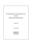
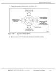
1
Operation and Service Manual
High Voltage Power Supplies
PS355, PS365, PS370, PS375
Stanford Research Systems
Revision 1.0 · December, 2008
Certification
Stanford Research Systems certifies that this product met its published specifications at the time
of shipment.
Warranty
This Stanford Research Systems product is warranted against defects in materials and workmanship
for a period of one (1) year from the date of shipment.
Service
For warranty service or repair, this product must be returned to a Stanford Research Systems
authorized service facility. Contact Stanford Research Systems or an authorized representative
before returning this product for repair.
Contact Information
Stanford Research Systems, Inc.
1290-D Reamwood Avenue
Sunnyvale, CA 94089 USA
Phone: (408)744-9040
Fax: (408)744-9049
www.thinkSRS.com
[email protected]
Information in this document is subject to change without notice.
Copyright © Stanford Research Systems, Inc., 2008. All rights reserved.
Printed in U.S.A.
Document number: 9-01637-903
Stanford Research Systems
PS300 Series High Voltage Power Supplies
Contents
General Information .
Symbols . . . . . . . .
Notation. . . . . . . .
Specifications . . . . .
.
.
.
.
.
.
.
.
.
.
.
.
.
.
.
.
.
.
.
.
.
.
.
.
.
.
.
.
.
.
.
.
.
.
.
.
.
.
.
.
.
.
.
.
.
.
.
.
.
.
.
.
.
.
.
.
.
.
.
.
.
.
.
.
.
.
.
.
iii
iv
v
vi
1
Instrument Overview . . . . . . . . . . . . . . . . .
1.1 Front Panel . . . . . . . . . . . . . . . . . . . .
1.2 Rear Panel . . . . . . . . . . . . . . . . . . . .
1–1
1–2
1–3
2
Guide to Operation . . . . . . . . .
2.1 Se ing Parameters . . . . . . .
2.2 Reset. . . . . . . . . . . . . . .
2.3 Store and Recall . . . . . . . .
2.4 Error Messages. . . . . . . . .
2.5 Analog Monitor and Control .
2.6 Default State . . . . . . . . . .
.
.
.
.
.
.
.
.
.
.
.
.
.
.
.
.
.
.
.
.
.
.
.
.
.
.
.
.
.
.
.
.
.
.
.
.
.
.
.
.
.
.
.
.
.
.
.
.
.
.
.
.
.
.
.
.
.
.
.
.
.
.
.
2–1
2–2
2–3
2–3
2–4
2–4
2–5
3
Remote Operation . . . . . . . . . . .
3.1 Index of Common Commands .
3.2 Alphabetic List of Commands .
3.3 Introduction . . . . . . . . . . .
3.4 Commands . . . . . . . . . . . .
3.5 Status Model . . . . . . . . . . .
3.6 Status Reporting . . . . . . . . .
.
.
.
.
.
.
.
.
.
.
.
.
.
.
.
.
.
.
.
.
.
.
.
.
.
.
.
.
.
.
.
.
.
.
.
.
.
.
.
.
.
.
.
.
.
.
.
.
.
.
.
.
.
.
.
.
3–1
3–2
3–3
3–4
3–4
3 – 12
3 – 13
4
Troubleshooting . . . . . . . . . . . . . . . . . . . .
4.1 Troubleshooting the PS300 . . . . . . . . . . .
4–1
4–2
i
ii
Contents
Stanford Research Systems
PS300 Series High Voltage Power Supplies
General Information
The PS300 Series High Voltage Power Supplies are general purpose
instruments designed for laboratory environments.
Warning
This unit contains hazardous high voltages. Make certain the high
voltage is completely discharged before removing the cable. The
charge on the cable can cause injury or damage.
Line Voltage
The PS300 series supplies operate from a 90 VAC to 264 VAC
power source having a line frequency between 47 Hz and 63 Hz.
Power consumption is less than 80 VA total.
A power entry module, labeled AC POWER on the back panel of the
PS300, provides connection to the power source and to a protective
ground.
The PS300 uses a detachable, three-wire power cord for connection to
the power source. The exposed metal parts of the box are connected
to the power ground to protect against electrical shock. Always use
an outlet which has a properly connected protective ground.
The rear-panel high voltage connector and the BNC shields are also
connected to chassis ground. The PS300 series supplies CANNOT
be floated.
The line fuse is internal to the instrument and may not be serviced
by the user. Operate only with covers in place to avoid personal
injury. Do not remove the product covers or panels. Do not operate
the product without all covers and panels in place.
Service
The PS300 does not include any user-serviceable parts inside. Refer
service to a qualified technician.
iii
iv
Contents
Symbols you may find on SRS products
Symbol
Description
Alternating current
Caution - risk of electric shock
Frame or chassis terminal
Caution - refer to accompanying documents
Earth (ground) terminal
Battery
Fuse
On (supply)
Off (supply)
Stanford Research Systems
PS300 Series High Voltage Power Supplies
v
Contents
Notation
Typese ing conventions used in this manual are as follows:
· Front-panel bu
ons are represented as [Bu on]
· The [▲] and [▼] keys increment and decrement a digit.
· The [◄] and [►] keys select a digit.
· Front-panel indicators are represented as Overload
· The state of a switch is represented in italics as ON
· Remote command names are represented as *IDN?
· Literal text other than command names is represented as OFF
Remote command examples will all be set in monospaced font.
In these examples, data sent by the host computer is set as
straight teletype font, while responses received by the
host computer are set as slanted teletype font.
PS300 Series High Voltage Power Supplies
Phone: (408)744-9040
www.thinkSRS.com
vi
General Information
Specifications
Model
Output Voltage (±)
Maximum Current
PS355
PS365
PS370
PS375
-100 V to -10 kV
+100 V to +10 kV
-100 V to -20 kV
+100 V to +20 kV
1 mA
1 mA
500 µA
500 µA
Voltage Output
Voltage set accuracy
Voltage display accuracy
Voltage resolution
Voltage rese ability
Voltage limit range
Voltage regulation
Output ripple (rms)
Current limit range
Current trip range
Trip response time
Current set accuracy
Current resolution
Current display accuracy
Stability
Temperature dri
Protection
HV output slew rate
Recovery time
Discharge time
0.01 % + 0.05 % of full scale
Vset accuracy ± 1 V, typ. (± 2 V, max.)
1 V (set and display)
1V
0 to 100 % of full scale
0.001 % for ±10 % line change,
0.04 % for 100 % load change.
Specifications apply for >0.5 % (full load) to
>1 % (no load) of full-scale voltage.
<0.01 % of full scale (max.)
0 to 105 % of full scale
0 to 105 % of full scale
<10 ms
1 µA
1 µA
±1 µA (typ.), ±2 µA (max.)
0.01 % per hr., <0.03 % per 8 hrs.
50 ppm/°C, 0 to 50 °C (typ.)
Arc and short circuit protected (programmable
voltage limit, current limit, and current trip)
7,000 V/s, typ. (PS355 and PS365)
14,000 V/s, typ. (PS370 and PS375)
12 ms for 40 % step change in load current (typ.)
<6 s (to <1 % of full-scale voltage with no load, typ.)
Monitor Output
Output scale
Current rating
Output impedance
Stanford Research Systems
0 to +10 V
(0 to full-scale output regardless of polarity)
10 mA (max.)
<1 Ω
PS300 Series High Voltage Power Supplies
vii
General Information
Accuracy
Update rate
0.2 % of full scale
87.5 Hz
External Voltage Set
Input scale
Input impedance
Accuracy
Update rate
0 to +10 V
(0 to full-scale output regardless of polarity)
1 MΩ
0.2 % of full scale
87.5 Hz
Mechanical
HV connector
Mating connector
Dimensions
Weight
Power
Warranty
Kings type 1064-1 (PS355 and PS365)
Kings type 1764-1 (PS370 and PS375)
Kings type 1065-1 (PS355 and PS365)
Kings type 1765-1 (PS370 and PS375)
8.1″ × 3.5″ × 16″ (WHD)
8 lbs.
50 W, 90 to 264 VAC, 47 to 63 Hz
One year parts and labor on defects in materials
or workmanship
All performance specifications apply aĞer a one hour warm-up period
PS300 Series HighVoltage Power Supplies
Phone: (408)744-9040
www.thinkSRS.com
General Information
PS300 Series HighVoltage Power Supplies
viii
Phone: (408)744-9040
www.thinkSRS.com
1 Instrument Overview
In This Chapter
This chapter gives the user the necessary information to get
started with the PS300 Series High Voltage Power Supplies.
1.1
1.2
Front Panel . . . . . . . . . . . . . .
1.1.1 Power Bu on . . . . . . . .
1.1.2 High Voltage Enable Switch
1.1.3 Numeric Displays . . . . . .
1.1.4 Select, Enter, Clear . . . . .
1.1.5 Numeric and Cursor Keys .
1.1.6 Instrument Status . . . . . .
1.1.7 Other Keys . . . . . . . . . .
1.1.8 Store and Recall . . . . . . .
Rear Panel. . . . . . . . . . . . . . .
1.2.1 Power Entry Module . . . .
1.2.2 High Voltage Connector . .
1.2.3 Analog I/O . . . . . . . . . .
1.2.4 IEEE-488 Port . . . . . . . .
1.2.5 RS-232 Port. . . . . . . . . .
.
.
.
.
.
.
.
.
.
.
.
.
.
.
.
.
.
.
.
.
.
.
.
.
.
.
.
.
.
.
.
.
.
.
.
.
.
.
.
.
.
.
.
.
.
.
.
.
.
.
.
.
.
.
.
.
.
.
.
.
.
.
.
.
.
.
.
.
.
.
.
.
.
.
.
.
.
.
.
.
.
.
.
.
.
.
.
.
.
.
.
.
.
.
.
.
.
.
.
.
.
.
.
.
.
.
.
.
.
.
.
.
.
.
.
.
.
.
.
.
.
.
.
.
.
.
.
.
.
.
.
.
.
.
.
1–2
1–2
1–2
1–3
1–3
1–3
1–3
1–3
1–4
1–4
1–4
1–4
1–5
1–5
1–5
1–1
1–2
Instrument Overview
1.1 Front Panel
The front-panel features of the PS300 Series High Voltage Power
Supplies are examined in this section.
1.1.1 Power Button
The PS300 is turned on by depressing the [POWER] bu on. The
unit always powers up with the high voltage OFF. The current
instrument configuration and any saved instrument presets are
stored in non-volatile memory. The model number (355, 365, 370
or 375), firmware version, and serial number are displayed when
power is turned on. If an error appears on power up, the current
instrument configuration and any saved presets are lost, and the
default se ings are used. If the default se ings are desired, hold
down the clear key [CLR] while turning on the power. Note that
this will clear out all buffers and erase any saved presets.
1.1.2 High Voltage Enable Switch
The [High Voltage] enable switch has three positions that perform
several functions. In the down position, the high voltage is OFF,
and all trips are cleared. In this position, the high voltage is locked
OFF and cannot be turned on over the computer interface. The
UP position is momentary, and it turns on the high voltage for
manual or rear-panel analog control. In the middle position, the
high voltage is enabled (but not necessarily ON) and can be turned
on over the computer interface. The large red ON LED above the
switch indicates that the high voltage is on; the yellow TRIP LED
indicates a trip has occurred.
Stanford Research Systems
PS300 Series High Voltage Power Supplies
1–3
Front Panel
1.1.3 Numeric Displays
The two large displays show output voltage to five significant digits
and output current to four significant digits. The polarity is indicated
below the voltage display as either POSITIVE or NEGATIVE. The
smaller center display shows the value of the parameter that is
being entered or adjusted. That parameter is indicated by the row
of LEDs directly below the center display.
1.1.4 Select, Enter, Clear
[SELECT] is used to choose which parameter is being displayed in
the center display. [ENTER] confirms the entry in the center display.
[CLR] erases the value in the middle display and recalls the last
value that was entered. To adjust a value, [SELECT] is pressed until
the appropriate LED is lit. When the value is being changed, the LED
will flash to indicate the value is in a state of change. If an incorrect
value is entered, press [CLR] to start over. When the desired value
is displayed, [ENTER] updates the unit’s actual se ing and stops
the LED from flashing.
1.1.5 Numeric and Cursor Keys
All parameters may be adjusted using the cursor or numeric keys.
When using the cursor, the digit being adjusted in the center display
will flash. The [▲] and [▼] keys increment and decrement the digit.
The [◄] and [►] keys select the flashing digit. When using direct
numerical entry, simply press the number and decimal point keys
until the desired value appears on the center display. Note that the
current is specified in microamps.
1.1.6 Instrument Status
Three LEDs indicate the instrument’s status. The LIMIT LED is on
when the unit is in a current limit state. REM is on when the front
panel is locked out. REAR is on when the high voltage se ing is
programmed by the rear-panel analog input.
1.1.7 Other Keys
[RESET] toggles the reset mode between AUTO and MAN (manual).
[GPIB] displays the GPIB address in the center display so it can be
adjusted. It also functions as the [LOCAL] key when the unit is in
the remote mode.
PS300 Series High Voltage Power Supplies
Phone: (408)744-9040
www.thinkSRS.com
1–4
Instrument Overview
1.1.8 Store and Recall
Store [STO] and Recall [RCL] allow up to nine complete instrument
configurations to be saved in nonvolatile memory. [RCL] 0 recalls
the default se ings.
1.2 Rear Panel
The rear panel of the PS300 Series High Voltage Power Supplies is
discussed next.
1.2.1 Power Entry Module
The AC line cord plugs into the power entry module. Refer to the
General Information section of this manual for instructions on line
voltage.
1.2.2 High Voltage Connector
WARNING — This unit contains hazardous voltages. Please make
certain that the high voltage is completely discharged before
removing or connecting the high voltage cable. High voltage cables
can store charge. If they are disconnected from the supply while
high voltage is present, electric shock can occur which may cause
injury or damage the unit.
The high voltage output connector is a Kings type 1064-1 (PS355
and PS365) or a Kings type 1764-1 (PS370 and PS375). Please make
certain that the high voltage is completely discharged before
changing the cable. Cables are available from SRS.
Stanford Research Systems
PS300 Series High Voltage Power Supplies
1–5
Instrument Overview
1.2.3 Analog I/O
The two MONITOR output BNCs are used to monitor the voltage
and current signals. Both are 0 to +10 V outputs corresponding to
0 to full scale. The SET input BNC receives an analog programming
voltage, 0 to +10 VDC corresponding to 0 to full scale (independent
of high voltage polarity). To select the rear SET analog high voltage
control, press [SELECT] on the front panel until REAR is selected,
and then use the [▲] and [▼] keys to choose between “Front” and
“Rear”. Press [ENTER] to confirm the selection.
1.2.4 IEEE-488 Port
The 24-pin IEEE-488 (GPIB) connector allows computer control of
PS300 series supplies. The address is set from the front panel using
the [GPIB] key.
1.2.5 RS-232 Port
The 9-pin female D-sub connector allows computer control of
power supply via RS-232. The interface se ings are fixed as DCE,
9600 baud, no parity, 8 bits, 1 stop bit.
Stanford Research Systems
PS300 Series High Voltage Power Supplies
1–6
Instrument Overview
Stanford Research Systems
PS300 Series High Voltage Power Supplies
2 Guide To Operation
In This Chapter
This chapter explains how to operate the PS300 Series High
Voltage Power Supplies.
2.1
2.2
2.3
2.4
2.5
2.6
Se ing Parameters . . . . . . . . . .
2.1.1 Se ing the Output Voltage .
2.1.2 Se ing the Voltage Limit . .
2.1.3 Se ing the Current Limit . .
2.1.4 Se ing the Current Trip . .
Reset
. . . . . . . . . . . . . . . .
Store and Recall . . . . . . . . . . .
Error Messages . . . . . . . . . . . .
Analog Monitor & Control . . . . .
2.5.1 Voltage Set . . . . . . . . . .
2.5.2 Voltage Monitor . . . . . . .
2.5.3 Current Monitor. . . . . . .
Default State . . . . . . . . . . . . .
.
.
.
.
.
.
.
.
.
.
.
.
.
.
.
.
.
.
.
.
.
.
.
.
.
.
.
.
.
.
.
.
.
.
.
.
.
.
.
.
.
.
.
.
.
.
.
.
.
.
.
.
.
.
.
.
.
.
.
.
.
.
.
.
.
.
.
.
.
.
.
.
.
.
.
.
.
.
.
.
.
.
.
.
.
.
.
.
.
.
.
.
.
.
.
.
.
.
.
.
.
.
.
.
.
.
.
.
.
.
.
.
.
.
.
.
.
2–2
2–2
2–2
2–3
2–3
2–3
2–3
2–4
2–4
2–4
2–4
2–4
2–5
2–1
2–2
Guide to Operation
2.1 Setting Parameters
This section describes how to set the front-panel parameters.
2.1.1 Setting the Output Voltage
The voltage set can be changed with the high voltage in either the
ON or OFF mode.
To set the high voltage output, press the [SELECT] key until the
voltage SET LED is lit. The present value of the set voltage will
be displayed in the center window. To change the value, enter the
desired voltage by using either the numeric keys or cursor. A er the
new value has been entered into the center display, press [ENTER]
to update the output voltage. The voltage SET LED will flash until
[ENTER] or [CLR] is pressed to remind you that the displayed value
is not the actual programmed value. If an Err2 message appears
(illegal parameter entered), check the voltage limit to see that it is
greater than or equal to the desired set voltage. Use the [CLR] key
to clear any error message.
If the REAR status LED is lit, the high voltage is programmed from
the analog set input on the rear panel. In this mode, if the center
display is showing voltage SET, the displayed value is the present
value of the high voltage programmed by the 0 to 10 V input and
cannot be adjusted from the front panel.
2.1.2 Setting the Voltage Limit
The voltage limit is a protection feature to prevent the output voltage
from being set too high or overshooting because of dramatic load
changes. The output voltage cannot be set higher than the voltage
limit. In addition, if the output ever exceeds the limit by more than
2 % of full scale, the unit trips and the high voltage is disabled. If
this occurs, a VTRP (voltage trip) message appears in the middle
display.
A er a trip, it is not necessary to clear the trip before turning the
high voltage back on. If it is necessary to change a parameter before
turning the high voltage back on, pressing [CLR] or pu ing the
high voltage switch in the OFF position will clear the trip.
To set the voltage limit, press [SELECT] until the voltage LIMIT
LED is lit. The present value of the voltage limit is displayed in
the center window. Change it with either the numeric keys or the
Stanford Research Systems
PS300 Series High Voltage Power Supplies
2–3
Se ing Parameters
cursor and press [ENTER] to update the actual limit value. If an
Err2 message appears (illegal parameter entered), check to see that
the output voltage is less than or equal to the voltage limit.
2.1.3 Setting the Current Limit
Current limiting varies the output voltage to limit the output current
to less than or equal to the programmed current limit value. When
the unit is current limited, the LIMIT LED is lit. The current limit is
set in the same fashion as the voltage limit — selecting the present
value on the center window, changing it and then entering the new
value.
2.1.4 Setting the Current Trip
The current trip shuts off the high voltage when the output current
exceeds the trip value. The current trip value is set in the same
fashion as the voltage and current limits. A er a current trip occurs,
the ITRP (current trip) message will appear in the middle display.
Current trips are cleared just like voltage trips.
2.2 Reset
The reset mode determines how the unit responds a er a voltage
or current trip.
In MAN (manual) mode, the high voltage remains OFF a er a trip
and requires that the operator turn it back ON.
In AUTO (automatic) mode, the unit waits until the later of the time
for the output voltage to fall to 0.5 % of full-scale or two seconds,
and then turns the high voltage back ON. This is useful when
dealing with loads that occasionally short circuit but recover a er
removing the high voltage.
2.3 Store and Recall
The store and recall functions allow up to nine complete instrument
setups to be saved. To store a setup, press the [STO] key followed by
a number (1 to 9) and then the [ENTER] key. To recall a setup, press
the [RCL] key, followed by a number (0 to 9) and then the [ENTER]
key. [RCL] 0 returns the setup to the factory default. Whenever
a setup is recalled, the high voltage is turned off for safety. If an
Err3 (recall error) occurs, then that stored setup was lost due to a
memory error and must be re-entered.
PS300 Series High Voltage Power Supplies
Phone: (408)744-9040
www.thinkSRS.com
2–4
Guide to Operation
2.4 Error Messages
The following error messages may appear in the center display. The
[CLR] key clears the errors.
Err1
Memory error – Power on memory error of the unit’s
last setup. Default setup is recalled.
Err2
Illegal parameter entered.
Err3
Recall Error – the stored setup was lost.
Err4
Illegal storage address.
(Address 0 is reserved for default se ings)
Err5
Device dependent
Err6
Syntax error over GPIB.
Err7
Illegal parameter entered over GPIB.
Parameter entered is out of range.
Err 8
Remote communication error
Err9
Hardware watchdog
2.5 Analog Monitor & Control
2.5.1 Voltage Set
When configured for rear control (see § 1.2.3) the rear-panel SET
voltage will set the output voltage. When enabled, the REAR (rear
panel) status LED is lit, and the output voltage being set by the
rear panel is displayed in the middle display (when it is showing
voltage SET). The voltage limit is still active and does not allow
the rear-panel voltage to set the output above the voltage limit. If
the rear-panel voltage is too high, the output voltage will stop at
the limit voltage. An input from 0 to +10 V will program the high
voltage from 0 to full scale, regardless of polarity.
2.5.2 Voltage Monitor
The voltage monitor BNC is a monitor output providing 0 to +10
volts for a 0 to full-scale output, regardless of polarity.
Stanford Research Systems
PS300 Series High Voltage Power Supplies
2–5
Analog Monitor and Control
2.5.3 Current Monitor
The current monitor output BNC provides a 0 to +10 volt output for
0 to full-scale output, regardless of the output polarity.
2.6 Default State
The factory default setup can be recalled by pressing the [CLR] key
while turning the unit on, or recalling setup 0. Note that pressing
the [CLR] key while turning the unit on will also clear all buffers
and erase any saved presets. The default setup is also recalled a er
a power on memory error (ERR 1). The default parameters are
shown below.
PS355
Voltage Set
Voltage Limit
Current Limit
Current Trip
Reset Mode
High Voltage
GPIB Addr
0V
₋10,000 V
₋1,050 µA
₋1,050 µA
MAN
OFF
14
PS365
Voltage Set
Voltage Limit
Current Limit
Current Trip
Reset Mode
High Voltage
GPIB Addr
0V
+10,000 V
+1,050 µA
+1,050 µA
MAN
OFF
14
PS370
Voltage Set
Voltage Limit
Current Limit
Current Trip
Reset Mode
High Voltage
GPIB Addr
0V
₋20,000 V
₋525 µA
₋525 µA
MAN
OFF
14
PS375
Voltage Set
Voltage Limit
Current Limit
Current Trip
Reset Mode
High Voltage
GPIB Addr
0V
+20,000 V
+525 µA
+525 µA
MAN
OFF
14
PS300 Series High Voltage Power Supplies
Phone: (408)744-9040
www.thinkSRS.com
2–6
Guide to Operation
Stanford Research Systems
PS300 Series High Voltage Power Supplies
3 Remote Operation
In This Chapter
This chapter describes operating the PS300 series over the RS-232
and GPIB computer interfaces.
3.1
3.2
3.3
3.4
3.5
3.6
Index of Common Commands . . . .
Alphabetic List of Commands . . . .
Introduction . . . . . . . . . . . . . .
3.3.1 Power-On Configuration . . .
3.3.2 Buffers . . . . . . . . . . . . .
Commands . . . . . . . . . . . . . . .
3.4.1 Command Syntax . . . . . . .
3.4.2 Notation . . . . . . . . . . . .
3.4.3 Examples . . . . . . . . . . . .
3.4.4 Output Control Commands .
3.4.5 Se ing Control Commands .
3.4.6 Interface Control Commands
3.4.7 Status Reporting Commands
Status Model . . . . . . . . . . . . . .
Status Reporting . . . . . . . . . . . .
3.6.1 Serial Poll Status Byte. . . . .
3.6.2 Standard Event Status Byte .
3.6.3 GPIB Error Messages . . . . .
.
.
.
.
.
.
.
.
.
.
.
.
.
.
.
.
.
.
.
.
.
.
.
.
.
.
.
.
.
.
.
.
.
.
.
.
.
.
.
.
.
.
.
.
.
.
.
.
.
.
.
.
.
.
.
.
.
.
.
.
.
.
.
.
.
.
.
.
.
.
.
.
.
.
.
.
.
.
.
.
.
.
.
.
.
.
.
.
.
.
.
.
.
.
.
.
.
.
.
.
.
.
.
.
.
.
.
.
.
.
.
.
.
.
.
.
.
.
.
.
.
.
.
.
.
.
.
.
.
.
.
.
.
.
.
.
.
.
.
.
.
.
.
.
3–2
3–3
3–4
3–4
3–4
3–4
3–4
3–5
3–5
3–6
3–6
3–8
3 – 10
3 – 12
3 – 13
3 – 13
3 – 14
3 – 14
3–1
3–2
Remote Operation
3.1 Index of Common Commands
Symbol
i
x
Definition
Unsigned integer
Assigned value
(?)
var
{var }
Required for queries; illegal for set commands
Parameter always required
Parameter required for set commands; illegal
for queries
Optional for both set and query commands
[var ]
Output Commands
HVOF
3–6
HVON
3–6
IOUT?
3–6
VOUT?
3–6
High Voltage Off
High Voltage On
Output Current
Output Voltage
Setting Control Commands
3 – 6 Recall
*RCL i
*SAV i
3 – 7 Save
ILIM(?) {x }
3 – 7 Current Limit
ITRP(?) {x }
3 – 7 Current Trip
SMOD(?) {i }
3 – 7 V Set Mode
TCLR
3 – 7 Trip Clear
TMOD(?) {i }
3 – 8 Trip Mode
VLIM(?) {x }
3 – 8 Voltage Limit
VSET(?) {x }
3 – 8 Voltage Set
Interface Control Commands
*RST
3 – 8 Reset
*IDN?
3 – 9 Identify
*OPC(?)
3 – 9 Operation Complete
LERR?
3 – 9 Last Error
Status Reporting Commands
*CLS
3 – 10 Clear Status
*ESE(?) i
3 – 10 Standard Event Status Enable
*ESR? [i]
3 – 10 Standard Event Status
*PSC(?) {i }
3 – 11 Power-On Status Clear
*SRE(?) {i}
3 – 11 Service Request Enable
3 – 11 Status Byte
*STB(?) [i ]
Stanford Research Systems
PS300 Series High Voltage Power Supplies
3–3
Remote Operation
3.2 Alphabetic List of Commands
*
*CLS
*ESE(?) i
*ESR? [i]
*IDN?
*OPC(?)
*PSC(?) {i }
*RCL i
*RST
*SAV i
*SRE(?) {i }
*STB(?) [i]
3 – 10
3 – 10
3 – 10
3–9
3–9
3 – 11
3–6
3–8
3–7
3 – 11
3 – 11
Clear Status
Standard Event Status Enable
Standard Event Status
Identify
Operation Complete
Power-On Status Clear
Recall
Reset
Save
Service Request Enable
Status Byte
H
HVOF
HVON
3–6
3–6
High Voltage Off
High Voltage On
I
ILIM(?) {x }
IOUT?
ITRP(?) {x }
3 – 7 Current Limit
3 – 6 Output Current
3 – 10 Current Trip
L
LERR?
3–9
Last Error
S
SMOD(?) {i }
3–7
V Set Mode
T
TCLR
TMOD(?) {i }
3–7
3–8
Trip Clear
Trip Mode
V
VLIM(?) {x }
VOUT?
VSET(?) {x }
3–8
3–6
3–8
Voltage Limit
Output Voltage
Voltage Set
PS300 Series High Voltage Power Supplies
Phone: (408)744-9040
www.thinkSRS.com
3–4
Remote Operation
3.3 Introduction
Remote operation of the PS300 series is through a simple command
language documented in this chapter. Both set and query forms of
most commands are supported, allowing the user complete control
of the instrument from a remote computer. Both RS-232 and GPIB
(IEEE488.2) interfaces are supported.
3.3.1 Power-On Configuration
The se ings for the RS-232 interface are 9600 baud and no parity.
The default GPIB address is 14. The complete instrument configuration is retained in non-volatile memory.
When appropriate, the default value for parameters is listed in
boldface in the command descriptions.
3.3.2 Buffers
The PS300 series stores incoming bytes in a 128 character input
buffer. Characters accumulate in the input buffer until a command
terminator (either CR or LF ) is received, at which point the message is parsed and executed. Query responses are buffered in a 128
character output queue.
< > < >
If the input buffer overflows, then all data in both the input buffer
and output queue are discarded, and an error is reported in the
Standard Event Status Byte.
3.4 Commands
This section provides syntax and operational descriptions for remote commands.
3.4.1 Command Syntax
The four le er mnemonic (shown in CAPS) in each command sequence specifies the command. The rest of the sequence consists of
parameters.
Commands may take either set or query form, depending on whether the “?” character follows the mnemonic. Set only commands are
listed without the “?”, query only commands show the “?” a er the
mnemonic, and optionally query commands are marked with a “(?)”.
Parameters shown in { } and [ ] are not always required. Parameters
in { } are required to set a value, and should be omi ed for queries.
Stanford Research Systems
PS300 Series High Voltage Power Supplies
3–5
Commands
Parameters in [ ] are optional in both set and query commands.
Parameters listed without surrounding characters are always required.
Do not send ( ) or { } or [ ] as part of the command.
Multiple parameters are separated by commas. Multiple commands
may be sent on one command line by separating them with semicolons (;) so long as the input buffer does not overflow. Commands
are terminated by either CR or LF characters. Null commands
and whitespaces are ignored. Execution of the command does not
begin until the command terminator is received.
< > < >
3.4.2 Notation
The following table summarizes the notation used in the command
descriptions.
Symbol
i
x
Definition
Unsigned integer
Assigned value
(?)
var
{var}
Required for queries; illegal for set commands
Parameter always required
Parameter required for set commands; illegal
for queries
Optional for both set and query commands
[var]
3.4.3 Examples
Each command is provided with a simple example illustrating its
usage. In these examples, all data sent by the host computer to the
PS300 are set as straight teletype font, while responses
received by the host computer from the PS300 are set as slanted
teletype font.
The usage examples vary with respect to set/query and optional
parameters. These examples are not exhaustive and are intended to
provide a convenient starting point for user programming.
PS300 Series High Voltage Power Supplies
Phone: (408)744-9040
www.thinkSRS.com
3–6
Remote Operation
3.4.4 Output Control Commands
HVOF
High Voltage Off
The HVOF command turns the high voltage output OFF.
Example: HVOF
HVON
High Voltage On
The HVON command turns the high voltage ON, provided the
front-panel high voltage switch is not in the OFF position. If the
switch is in the OFF position, the high voltage is le off and an
execution error is reported. This command also automatically
clears any voltage or current trips.
Example: HVON
IOUT?
Output Current
The IOUT? query returns the actual output current, in amperes.
This is the same value shown on the front-panel meter. The value
is always returned as an unsigned number, regardless of the
polarity of the power supply.
Example: IOUT?
4.78E-4
VOUT?
Output Voltage
The VOUT? query returns the actual output voltage, in volts. This is
the same value shown on the front-panel meter. The value
returned is a floating point value and includes the sign of the
output voltage.
Example: VOUT?
-1.8998E4
3.4.5 Setting Control Commands
*RCL i
Recall Configuration
The *RCL command recalls stored se ings i. *RCL 0 restores the
default se ings. If the stored se ing is corrupted, an error is returned.
Example: *RCL 3
Stanford Research Systems
PS300 Series High Voltage Power Supplies
3–7
Commands
*SAV i
Save Configuration
The *SAV command stores the present setup as se ing i. i may
range from 1 to 9.
Example: *SAV 3
ILIM(?) {x }
Limit Current
The ILIM command sets (queries) the value of the current limit
(to x), in amperes. ILIM may be set from 0 to 105 % of full scale.
Example: ILIM 120E-6; ILIM?
1.20E-4
ITRP(?) {x }
Trip Current
The ITRP command sets (queries) the value of the current trip
(to x), in amperes. ITRP may be set from 0 to 105 % of full scale.
Example: ITRP? 5.25E-4
SMOD(?) {i }
Rear Programming Mode
The SMOD? command sets (queries) the VSet se ing mode. SMOD 0
means that the voltage value is controlled by the front-panel
se ing, while SMOD 1 indicates that the output is controlled by
the rear-panel VSET voltage control input.
Note that changing the SMOD value while the high voltage is ON
causes the high voltage to be switched OFF.
Example: SMOD 1
TCLR
Clear Trips
The TCLR command clears any voltage or current trips.
Example: TCLR
PS300 Series High Voltage Power Supplies
Phone: (408)744-9040
www.thinkSRS.com
3–8
Remote Operation
TMOD(?) {i}
Trip Mode
The TMOD command sets (queries) the trip reset mode {to i}. The
value i = 1 sets manual trip reset, while the value i = 1 sets the trip
reset mode to automatic.
Example: TMOD 1
VLIM(?) {x}
Voltage Limit
The VLIM command sets (queries) the value of the voltage limit
{to x}, in volts. The sign of value x must match the polarity of the
power supply. As with front-panel control, the VLIM value must be
greater than or equal to the VSET value or an execution error will
be returned.
Example: VLIM?
-2.0000E4
VSET(?) {x }
Voltage Set
The VSET command sets (queries) the value of the voltage se ing
{to x}, in volts. If SMOD 1 (rear-panel control) is enabled, then
se ing the VSET command returns an error. The value x must
match the polarity of the power supply.
When SMOD = 0 (front-panel control), the VSET? query returns
the set parameter (not the measured output voltage, see VOUT?
§ 3.4.4). When SMOD = 1 (rear-panel control), the VSET? query
returns the high voltage se ing programmed by the rear-panel
HVSET input. As with front-panel control, the VSET value must
be less than or equal to the VLIM value or an execution error will
be returned.
Example: VSET?
19555
3.4.6 Interface Control Commands
*RST
Reset
The *RST common command resets the power supply to its default
configuration. It is the same as holding the [CLR] bu on
depressed at power on.
Example: *RST
Stanford Research Systems
PS300 Series High Voltage Power Supplies
3–9
Commands
*IDN?
Identify
The *IDN? common query returns the PS300’s device identification.
This string is forma ed as follows:
StanfordResearchSystems, PS3XX, <serial>, <version>
where XX is the model number, <serial> is the 6-digit serial
number of the unit, and <version> is the 3-digit firmware
revision number.
Example: *IDN?
StanfordResearchSystems,PS370,100003,0.29
*OPC(?)
Operation Complete
The *OPC common command causes remote command execution
to pause until all pending operations are complete. The *OPC?
query will return the value “1” when operations are complete,
while the *OPC set command will set the OPC bit (bit 0) in the
ESR register.
Example: *OPC?
1
LERR?
Last Error
The LERR? query returns the error code of the last remote interface
error. A list of the possible error codes are as follows:
Code
10
100
101
102
103
110
111
112
113
114
115
116
117
118
119
PS300 Series High Voltage Power Supplies
Meaning
Illegal value (execution)
Lost data (query)
No data (query)
No listener (query)
Overflow (query)
Illegal command (parser)
Undefined command (parser)
Illegal query (parser)
Illegal set (parser)
Null parameter (parser)
Extra parameter (parser)
Missing parameter (parser)
Overflow (parser)
Bad float (parser)
Float overflow (parser)
Phone: (408)744-9040
www.thinkSRS.com
3 – 10
Remote Operation
120
121
122
123
124
125
126
151
152
153
154
155
Bad integer (parser)
Integer overflow (parser)
Bad hex value (parser)
Hex overflow (parser)
Bad token integer (parser)
Unknown token (parser)
Syntax error (parser)
CMF reset (device dependent)
COP reset (device dependent)
Illegal reset (device dependent)
Recall error (device dependent)
Watchdog (device dependent)
Example: *IDN; LERR?
113
3.4.7 Status Reporting Commands
Clear Status
*CLS
The *CLS common command clears all status registers.
Example: *CLS
*ESE(?) i
Standard Event Enable
The *ESE common command sets (queries) the standard event
status enable register {to i}. The parameter i is the decimal value
for the enable register, and can range from 0 to 255.
Example: *ESE 16
*ESR? [i]
Standard Event
The *ESR common command query reads the value of the
standard event status register. If the optional parameter i is
present, then only the value of bit i is returned. Reading this
register will clear it. Reading bit i will clear bit i only.
Example: *ESR? 5
1
Stanford Research Systems
PS300 Series High Voltage Power Supplies
3 – 11
Commands
*PSC(?) {i }
Power-On Status Clear
The *PSC common command sets (queries) the value of the
power-on status clear bit {to i}. If i = 1, the power-on status clear
bit is set, and all status registers and enable registers are cleared
on power up. If i = 0, the bit is cleared, and the status enable
registers maintain the values at power down. This allows the
generation of a service request at power up, for example.
Example: *PSC?
1
*SRE(?) {i }
Service Request Enable
The *SRE common command sets (queries) the value of the service
request enable register {to i}.
Example: *SRE 6
*STB? [i ]
Standard Byte
The *STB? common command query reads the value of the serial
poll status byte. If the optional parameter i is present, the value
of bit i is returned. Reading this register will clear bits 1, 2, and 3;
the remaining bits are either real-time monitors of underlying
conditions (such as bit 7: HVON), or summary bits (such as
bit 5: ESB).
Example: *STB?
129
PS300 Series High Voltage Power Supplies
Phone: (408)744-9040
www.thinkSRS.com
3 – 12
Remote Operation
3.5 Status Model
The PS300 series instruments follow the hierarchical IEEE-488.2
format. A block diagram of the status register array is given in Figure 3.1
Standard Event Status
PON: Power On 7
URQ: User Request 6
CME: Command Error 5
7
EXE: Execution Error 4
DDE: Device Error 3
4
QYE: Query Error 2
undef 1
2
1
OPC: Operation Complete 0
0
ESR
6
5
3
ESE
Status Byte
7
7 HVON: High Voltage ON
6
X RQS / MSS: Master Summary Status
5
5 ESB: Event Status Bit
4
4 MAV: Message Available
3
3 ILIM: Current Limit
2
2 ITRIP: Current Trip
1
1 VTRIP: Voltage Trip
0
SB
0 STABLE: High Voltage Stable
SRE
Figure 3.1: Status register model for the PS300 series High Voltage Power
Supplies.
The two categories of registers in the PS300 series status model are
as follows:
Event Registers
These read-only registers record the occurrence of defined events.
If the event occurs, the corresponding bit is set to 1. Upon querying
an event register, all set bits within it are cleared. These are sometimes known as sticky bits, since once set, a bit can only be cleared
by reading its value. Event register names end with SR.
Enable Registers
These read/write registers define a bitwise mask for their corresponding event register. If a bit position is set in an event register
while the same bit position is also set in the enable register, then the
corresponding summary bit message is set. Enable register names
end with SE.
At power-on, all status registers are cleared.
Stanford Research Systems
PS300 Series High Voltage Power Supplies
3 – 13
Status
3.6 Status Reporting
The PS300 series reports on its status by means of two status bytes:
The serial poll byte and the standard status byte.
Upon power-on, the instrument may either clear all of its status
enable registers, or maintain them in the state they were in during
power-down. The action taken is set by the *PSC command and allows things such as SRQ on power-on to be produced if desired.
3.6.1 Serial Poll Status Byte
Bit
0
Name
stable
1
2
3
vtrip
itrip
ilim
4
5
MAV
ESB
6
7
RQS/MSS
hvon
Usage
Indicates VSET or ILIM value is stable. The
value depends on whether the PS300 is in
contant current or constant voltage mode.
Indicates a voltage trip has occurred
Indicates a current trip has occurred
Indicates a current limit condition has
occurred
Indicates GPIB output queue is non-empty
Indicates an unmasked bit in the standard
status byte has been set
SRQ bit
Indicates high voltage is on
The PS300 will make a service request (SRQ) whenever one of these
bits is set and the corresponding bit in the serial poll enable register
is set. Note that any status condition will produce only one SRQ
even if it is never cleared. The vtrip, itrip and ilim bits are latched
bits. They are set on the occurrence of the appropriate event and
stay set until either the status byte is read or the *CLS command is
sent. This allows one to detect if a trip condition has ever occurred.
All the other bits indicate the current states of their respective functions.
PS300 Series High Voltage Power Supplies
Phone: (408)744-9040
www.thinkSRS.com
3 – 14
Remote Operation
3.6.2 Standard Event Status Byte
Bit
0
1
2
3
4
5
6
7
Name
OPC
unused
Query Error
Recall Err
Execution Err
Usage
Set by *OPC
Set by an output queue overflow
Set if a stored se ing is corrupt
Set by an out-of-range parameter or
incomplete command.
Command Err Set by a command syntax error or an
unrecognizable command
URQ
Set by any key press
PON
Set by a power-on condition
This status byte is defined by IEEE488.2 (1987) and is used primarily to report errors in commands received over the communication
interface. Once set, the bits in this register stay set, and are cleared
when read or when a *CLS command is received.
If a bit in the standard status register is set, and the corresponding
bit in the standard status enable register is set, then the ESB bit in
the serial poll register is set.
3.6.3 GPIB Error Messages
If an error occurs due to an incomplete command, the following error messages will appear on the middle display:
Err6 Syntax Error Over GPIB
The command has an error in syntax or was unrecognizable.
This is the same error as seen in the Command Error (bit 5)
of the Standard Event Status Byte.
Err7 Illegal Parameter Entered Over GPIB
A parameter was set out-of-range, or a command could not
be completed because of an overload condition. This is the
same error seen in the Execution Err (bit 4) of the Standard
Event Status Byte.
Err8 GPIB Output Queue Full
The output queue overflowed and was cleared. This could
be due to querying the instrument repeatedly and not
Stanford Research Systems
PS300 Series High Voltage Power Supplies
3 – 15
Status
reading back all the bytes. This is the same error seen in the
Query Error (bit 2) of the Standard Event Status Byte.
PS300 Series High Voltage Power Supplies
Phone: (408)744-9040
www.thinkSRS.com
3 – 16
Remote Operation
Stanford Research Systems
PS300 Series High Voltage Power Supplies
4 Troubleshooting
In This Chapter
This chapter is wri en to guide a qualified electronics technician
through troubleshooting the PS300 Series Power Supplies.
4.1
Troubleshooting the PS300 . .
4.1.1 Power On Reset . . . .
4.1.2 Stuck Keys . . . . . . .
4.1.3 No High Voltage . . .
4.1.4 Repeated Trips. . . . .
4.1.5 Rear-Panel Voltage Set
4.1.6 Front-Panel Test . . . .
4.1.7 Calibration . . . . . . .
.
.
.
.
.
.
.
.
.
.
.
.
.
.
.
.
.
.
.
.
.
.
.
.
.
.
.
.
.
.
.
.
.
.
.
.
.
.
.
.
.
.
.
.
.
.
.
.
.
.
.
.
.
.
.
.
.
.
.
.
.
.
.
.
.
.
.
.
.
.
.
.
.
.
.
.
.
.
.
.
.
.
.
.
.
.
.
.
.
.
.
.
.
.
.
.
4–2
4–2
4–2
4–2
4–2
4–3
4–3
4–3
4–1
4–2
Troubleshooting
4.1 Troubleshooting the PS300
Verify that the line cord is plugged all the way into the power entry
module, and the power bu on on the front panel is pressed in.
4.1.1 Power On Reset
If the instrument turns on with odd combinations of illuminated
LEDs, garbled displays, or is unresponsive to the keyboard, the
memory contents may have been corrupted. To remedy the situation,
turn the unit off, and hold down the [CLR] key while turning the
power back on. This causes the unit to initialize the memory and
load the default setup.
4.1.2 Stuck Keys
If the center display is filled with a particular number (like 4444), or
one particular message (like Err2), and the keyboard is unresponsive,
check to see if a key is stuck down. If so, gently flick the stuck key
back to the center of its hole.
4.1.3 No High Voltage
Check to make sure that the HIGH VOLTAGE LED is ON. If the
HIGH VOLTAGE LED is OFF, check the following:
1) Check the voltage limit and current trip levels to see that they are
not too low for your load.
If the HIGH VOLTAGE LED is ON but the output voltage is zero or
lower than expected, check the following:
1) Check if the LIMIT LED is ON. If so, the current limit value could
be too low, or the load could be drawing excessive current.
2) Make sure the voltage limit is as large or larger than the desired
output voltage.
3) Check the REAR status LED. If it is ON, then the high voltage
is being programmed by the analog set voltage input on the rear
panel and not by the front panel. If so, make sure the rear-panel
programming voltage is correct.
4.1.4 Repeated Trips
Repeated trips can be caused by a change in load, or a load that is
Stanford Research Systems
PS300 Series High Voltage Power Supplies
4–3
Troubleshooting
drawing too much current. This may effect the voltage trip or the
current trip.
Voltage Trips
A voltage trip may occur if the load changes too rapidly, causing
the voltage to overshoot. Raising the voltage limit may eliminate
the problem.
Current Trips
Disconnect the load and see if the unit still trips. If it works with
no load, there may be a problem with the load. If it still trips,
the unit may be damaged. Please contact the factory for further
information.
4.1.5 Rear-Panel Voltage Set
If the output voltage output is inaccurate, check the REAR status
LED and rear-panel connection to see that it is in the SET BNC.
Make certain the voltage limit is set higher than the desired voltage.
4.1.6 Front-Panel Test
To test the front panel, hold down the [ENTER] key while turning
on the unit. A er power is turned on, you should see all indicators
and numeric segments (except for HV ON) lit. By pressing the [▲]
arrow key, individual annunciator lamps will light one by one
across the front panel, except again for the HV ON indicator, which
is controlled directly by hardware wired to the high voltage enable
circuitry. Continue pressing the [▲] key to then test the individual
segments of the numeric displays. A er the final segment (the
decimal point), press [▲] again and all digits will be lit as “8”. At
this point, press the [AUTO/MANUAL] bu on (upper-le most
bu on), and the display should read “0”. Continue across the front
panel, testing each bu on, which should display a unique key code
per bu on. The codes increase from top to bo om and le to right.
A er this test, turn the power off and restart the instrument.
4.1.7 Calibration
The calibration parameters are determined by a computer aided
calibration procedure at the factory. These values are stored in the
permanent memory of each unit. Because of this, there are no useradjustable components to calibrate.
PS300 Series High Voltage Power Supplies
Phone: (408)744-9040
www.thinkSRS.com
4–4
Troubleshooting
Stanford Research Systems
PS300 Series High Voltage Power Supplies