1
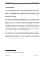
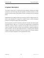
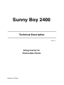
Sunny Boy 2400
Technical Description
Issue 1.1
String Inverter for
Photovoltaic Plants
SB2400-11:EE2900
Sunny Boy 2400
Technical Description
Alteration Review
DocumentNumber
SB2400
1
)
Issue
and Alteration
1
Review )
Comments
Author
-11:EE2100
1.1
A
Derived from Document “GCI-31:EE1200”
Name changed, specification of grid fuse included
Salisbury
-11:EE2900
1.1
A
Graphics repaired, minor changes in text.
Salisbury
A: Changes due to faulty documents or improvement of the documentation
B: Changes maintaining full or upward compatibility
C: Changes limiting or excluding compatibility
Name
Release
SB2400-11:EE
Date
Signature
Frank Greizer
-2-
SMA Regelsysteme GmbH
Sunny Boy 2400
Technical Description
Explanation of Symbols used in this Document
To enable optimal usage of this manual and safe operation of the device during
installation, operation and maintenance routines, please note the following
description of symbols:
This indicates a feature that is important either for optimal and
comfortable usage or optimal operation of the system.
Example: “Useful C routines for this purpose are on the support disk.“
This indicates a fact or feature very important for the safety of the user
and / or can cause a serious hardware defect if not applied appropriately.
Example: “Disconnect the mains plug before opening the case!“
This indicates an example.
SB2400-11:EE
-3-
SMA Regelsysteme GmbH
Sunny Boy 2400
Technical Description
Table of Contents
1
Introduction................................................................................................................7
2
System Description ...................................................................................................8
3
2.1
String Technology .............................................................................................9
2.2
Diagnosis and Communication .......................................................................11
2.3
Technical design of the Sunny Boy 2400........................................................12
2.4
Disconnection from Grid (MSD) ......................................................................14
Installation ...............................................................................................................17
3.1
What must be done in case of transport damages? .......................................17
3.2
Placement of the Sunny Boy...........................................................................18
3.3
Electric Connection .........................................................................................23
3.3.1
Connection of the Sunny Boy 2400 to the Electricity Grid..........................25
3.3.2
Connection of the PV-panels......................................................................27
4
Commissioning........................................................................................................30
5
Operation and Failure Indication LEDs ...................................................................31
6
7
5.1
Operation Indicator .........................................................................................34
5.2
Earth Fault Indicator........................................................................................37
5.3
Failure Indication.............................................................................................41
System Monitoring and Diagnosis ...........................................................................46
6.1
Data Transmission via Powerline....................................................................46
6.2
Data Transmission with a Separate Data Cable .............................................50
6.2.1
Data transmission via RS232 .....................................................................51
6.2.2
Data transmission via RS485 .....................................................................55
6.3
Measuring Channels and Messages...............................................................65
6.4
Measurement Precision ..................................................................................67
Troubleshooting.......................................................................................................68
SB2400-11:EE
-4-
SMA Regelsysteme GmbH
Sunny Boy 2400
Technical Description
8
Warranty Regulations and Liability ..........................................................................70
9
Technical Data ........................................................................................................72
10
Appendix .................................................................................................................78
SB2400-11:EE
-5-
SMA Regelsysteme GmbH
Sunny Boy 2400
Technical Description
Important Safety Notice:
The Sunny Boy String Inverter may only be opened by qualified
personnel for both maintenance and commissioning.
The device can still be charged with very high hazardous voltages
even when disconnected from both AC and DC side.
For optimal safety follow all steps as described in chapter 3
“Installation“ when opening the device.
Never disconnect the PV-string from the Sunny Boy 2400 when it is
feeding to the grid. Disconnect the connection to the grid first, e.g.
with the fuse in the house distribution.
SB2400-11:EE
-6-
SMA Regelsysteme GmbH
Sunny Boy 2400
Technical Description
1 Introduction
You have decided to use one of the most sophisticated devices and for the most
® 1
advanced modular PV system technology by purchasing a Sunny Boy
String
Inverter. The Sunny Boy inverters are the first systems that utilize the String
Technology from SMA and convince with their outstanding qualities concerning the
efficiency and the reliability.
The Sunny Boys comply with all regulations from the VDEW (Association of German
Electricity Producers) for the supplementary grid feeding to the low voltage electricity
grid of the utility. This contains the regulations of the employee association
(Berufsgenossenschaft für Feinmechanik und Elektrotechnik) concerning the
“Independent Disconnection Device“ known as MSD (Mains monitoring device with
allocated Switching Devices) and the regulations of the DIN VDE 0126. Furthermore
the Sunny Boy complies with the according standards and the low voltage
regulations as certified in the CE declaration (see appendix).
In the following you will find the technical description of the Sunny Boy 2400. Don’t
worry about its size, it is not necessary to read everything. This technical description
is both installer’s guide and user manual, so it is used as reference for the
commissioning and as guideline on how to use all functions of the inverter optimally
and how you can extend your existing PV-plant.
1
Sunny Boy is a registered Trademark of SMA Regelsysteme GmbH
SB2400-11:EE
-7-
SMA Regelsysteme GmbH
Sunny Boy 2400
Technical Description
2 System Description
The need to reduce the CO² emission and other pollutants resulting from energy
conversions is becoming more and more apparent. The direct conversion of solar
radiation to electric energy (Photovoltaics) will play a substantial role in this essential
matter.
Supplementary grid feeding includes the conversion of the DC voltage from the PVpanel to grid compatible AC voltage with so-called “inverters“ and the subsequent
connection to the electricity grid in the house distribution.
Here the electricity from the PV-modules provides all consumers with electric power
(household devices, lights etc.). In case that not enough energy is produced the
additionally necessary energy is obtained from the grid. In case that there is a
surplus of energy, this surplus is fed into the local grid and is therefore available for
other consumers. This way every single kilowatt-hour is utilized and the electricity
company’s power plants are relieved. In the most simple case a PV-plant therefore
consists of two basic components: the PV-panel and the inverter.
SB2400-11:EE
-8-
SMA Regelsysteme GmbH
Sunny Boy 2400
Technical Description
2.1 String Technology
The experience with several thousand grid-connected PV-systems in Europe with an
output range from one to several hundred kilowatts has shown that the costs for grid
connecting and monitoring the PV-system add up to almost 50 % of the costs for the
entire system. The reduction of these costs, especially the costs for the cabling on
the DC side and the subsequent distribution on the AC side, was the reason for
developing the string-technology from SMA. The Sunny Boy finally enabled the
String Technology to be the standard system design for PV-plants.
String Technology means that a small number of PV-modules are connected in
series to a “string“, each string is then connected to a separate inverter which feeds
the electricity of one string to the grid. Large PV-plants consist of a large number of
single strings. The produced energy is collected directly on the AC side, which
results in the fact that the system design gets very simple and no extraordinary DC
cabling is necessary anymore.
SB2400-11:EE
-9-
SMA Regelsysteme GmbH
Sunny Boy 2400
Technical Description
The most various system concepts can be realized with this strategy. A wide range
of different scaled inverters and peripheral components is available:
•
GCI 1000:
The small model for little PV-plants and simple extension
possibilities (3 input voltage and power ranges)
•
GCI 1200:
The output optimized inverter for PV-plants with at least 1 kWp
•
Sunny Boy 2400:
For PV-plants with up to 2.2 kWp and equipped with a wider
input voltage range
•
Sunny Data:
The PC-program for the communication with your Sunny Boy inverters
•
Sunny Boy Control:
The control unit for your PV-plant for data acquisition and evaluation
•
Sunny Data Control:
The PC-program for visualization of the data from your Sunny Boy Control
SB2400-11:EE
- 10 -
SMA Regelsysteme GmbH
Sunny Boy 2400
Technical Description
2.2 Diagnosis and Communication
The modular PV system technology leads to a spread out distribution of the Sunny Boy
String inverters. A simple and fast function monitoring of the status and measured
values for each single Sunny Boy is easy to achieve. The data is either displayed on
the LCD of the Sunny Boy Control or is shown on the screen of a PC running the
according SMA software. Two programs “Sunny Data“ and “Sunny Data Control“ are
based on a comfortable Windows GUI and allow the user to process the data with
other programs such as MS Excel.
The signal transmission between the PC and the single inverters is done with the
mains connection by using a Powerline modem integrated in the Sunny Boy which
results in the fact that no additional cables for data transmission lines are necessary.
Nevertheless a data transmission with RS232 or RS 485 is supported . Sunny Boy
Inverters support the following monitoring functions:
•
Continuous acquisition of operation data of all connected string inverters and
their PV-panels
•
Supervision of operating states and failure indication
•
Spot value transmission from single Sunny Boys
•
Identification of failures in the single strings
•
Graphical representation of the data from single Sunny Boys or comparison of
the data of several ones
•
System management, transmission of operation parameters
SB2400-11:EE
- 11 -
SMA Regelsysteme GmbH
Sunny Boy 2400
Technical Description
2.3 Technical design of the Sunny Boy 2400
The Sunny Boy inverter is based on a power unit that operates with a very high
efficiency and optimal reliability. A MOSFET bridge converts the voltage coming from
the PV modules to a high frequency secondary circuit with 16 kHz. The voltage is
then fed to the grid after being processed by a transformer.
Fig. 2.1: Block circuit diagram of the Sunny Boy 2400
The Sunny Boy 2400 is designed for 24 PV-modules with 36 to 40 cells each and
has a fixed input voltage range of 150 V to 300 V DC.
The current fed to the grid is perfectly sinus shaped and has a very low harmonic
distortion due to the fact that a one-chip computer manages the control. The
sequential control system takes care of the fully automatic operation and handles the
MPP-tracking (MPP = Maximum Power Point; fully automatic search for the PV
output voltage with highest output power). The sequential control system minimizes
unnecessary losses in standby and in grid feeding mode.
Ambient Temperature
The heat sink is necessary in order to let the energy resulting from the power
semiconductor devices dissipate. The heat sink is large enough to allow a
continuous operation of the Sunny Boy even in surroundings with high ambient
SB2400-11:EE
- 12 -
SMA Regelsysteme GmbH
Sunny Boy 2400
Technical Description
temperatures which are found e.g. directly under the roof with the panels. The Sunny
Boy 2400 can process short term output power of up to 1700 W and is equipped with
a temperature monitoring system that detects a too high heat sink temperature and
reduces the power fed to grid and nevertheless keeps feeding electricity to the grid.
Sequential Control System
The sequential control system also manages the communication with the system
monitoring tools Sunny Data and Sunny Data Control. The Sunny Boy therefore is
not only a simple standalone device as it can be part of one big PV-plant that has
one central control and monitoring facility.
MSD
Two independent one-chip computers monitor the grid. This fully complies with the
according regulations of the VDEW and the employee associations. The grid
monitoring is done by determining the grid impedance, a so-called MSD (Mains
monitoring with allocated Switching Devices, German = ENS). The relevant
regulations and standards of course must be kept to.
Stainless Steel Case
The case is made of stainless steel which protects the inverter from dust and water
up to IP 65. The Sunny Boy can therefore be mounted nearly anywhere inside or
outside the house with an ambient temperature range of -25°C to +60°C.
Personnel protection is a very important issue even with small PV-plants. The grid
and the PV-panels are electrically separated while the insulation is constantly
monitored. All applicable standards and regulations for personnel safety and EMC
are complied with.
SB2400-11:EE
- 13 -
SMA Regelsysteme GmbH
Sunny Boy 2400
Technical Description
2.4 Disconnection from Grid (MSD)
This section covers the safe disconnection and shutdown of the inverters in case the
public electricity grid goes down. This is an essential safety issue in order to make
sure that nobody working on the grid is harmed. It is important to detect an
“Islanding“ condition where the public grid is not running and the electricity
consumers and producers local to the PV-system are accidentally equal - resulting in
electricity circuits are on even though public grid is down. A VDEW regulation was
issued 1994, initiated by the “Berufsgenossenschaft für Feinmechanik und
Elektrotechnik“ (German Employee Association of Precision Mechanics and
Electronics Engineering).
The Sunny Boy string inverter is designed only for parallel operation with the
electricity grid. The inverter is equipped with an independent disconnection device
that has been certified by the “Berufsgenossenschaft für Feinmechanik und
Elektrotechnik“.
The regulation is called “Automatic disconnecting facility for photovoltaic
installations with a nominal output ≤ 4.6 kVA and a single phase parallel feed
by means of an inverter into the public low-voltage mains“.
For maximum safety this independent disconnection device consists of two separate
MSD (Mains monitoring with allocated Switching Devices) that are connected in
series. Each of these MSD constantly monitors the grid quality by checking the
frequency, voltage and impedance. The redundant circuit and an automatic self test
on each system startup ensure a reliable function of the disconnection.
The inverter islanding detection evaluates the grid impedance, the voltage and the
frequency of the connected phase.
SB2400-11:EE
- 14 -
SMA Regelsysteme GmbH
Sunny Boy 2400
Technical Description
Conditions that cause the Sunny Boy to be disconnected from the grid:
Grid Impedance
• The Sunny Boy does not start to feed to the grid if the grid impedance ZAC is higher
than 1,25 Ω
• The Sunny Boy is disconnected from the grid within 5 seconds once the grid
impedance increases drastically within a short time (∆ZAC ≥ 0,5 Ω) or the
impedance gets too high (ZAC ≥ 1,75 Ω).
Grid Voltage
• The grid voltage may be within a range of -15 % and +10 % of the nominal grid
voltage UN. Once the grid voltage exceeds this range the Sunny Boy is
disconnected from the grid within 0.2 s.
Grid Frequency
• The grid frequency may be within a range of ± 0.2 Hz of the nominal grid
frequency while the voltage is within a range of -30 % and +20 % of the nominal
grid voltage Un - once the frequency goes beyond this range the Sunny Boy is
disconnected from the grid within 0.2 s. The reliable measurement of the
frequency is given within -30 % and +20 % of the nominal grid voltage UN.
Furthermore the Sunny Boy disconnects from the grid within 0,2 seconds once the
grid frequency changes drastically exceeding a certain range.
This new Sunny Boy disconnection concept provides maximal safety with minimal
installation effort due to the fact that the connection of the MSD must only be done to
one single phase.
The value of the grid impedance is the sum of the impedance of the public grid and
the cabling impedance It is therefore necessary to calculate the impedance of the
connection cable to the inverter. (see chapter 3.3, “Connection of the Sunny Boy
2400 to the Electricity Grid“)
SB2400-11:EE
- 15 -
SMA Regelsysteme GmbH
Sunny Boy 2400
Technical Description
The MSD regulations require a type verification and test by an independent certified
testing association. It is also required that the supplier of the inverter tests every
single MSD before delivering the inverter to the customer.
The redundant design of the MSD and the regular self test on startup allow the user
to get along without periodic tests. Each startup includes the function test of the grid
in order to make sure that the allocated switching devices (transistor bridge and
relay) are operating. The self test is repeated in case the test result was negative - if
the failure persists the device must be checked by a qualified technician. The failure
is indicated by a warning LED meaning that the inverter is not feeding electricity to
the grid. The system shutdown because of MSD malfunction cannot be reset with
external signals in order to ensure that the device is checked and set up for grid
feeding only by qualified personnel.
SB2400-11:EE
- 16 -
SMA Regelsysteme GmbH
Sunny Boy 2400
Technical Description
3 Installation
The installation of the Sunny Boy string inverter must be done by
qualified personnel that are approved by the local electricity
company.
Make sure that all instructions in this chapter are followed.
Follow all safety regulations and regulations of the local electricity
company.
3.1 What must be done in case of transport damages?
The inverters are thoroughly checked before they are dispatched. Even though they
are delivered in a sturdy packaging (which can be recycled) the inverters can be
damaged in transit.
Please inspect your inverter thoroughly after it is delivered. If any damages can be
detected on the packaging that could lead to the conclusion that the contents is
damaged or if you detect that the inverter is damaged please immediately notify the
forwarding company.
SMA or your local supplier can help you in this matter. In any case the declaration of
transport damage must be made within 6 days upon receipt of the product and must
be stated in writing directly to the forwarding agent. If it is necessary to return the
inverter to the manufacturer please use the packaging the inverter was sent in.
SB2400-11:EE
- 17 -
SMA Regelsysteme GmbH
Sunny Boy 2400
Technical Description
3.2 Placement of the Sunny Boy
The Sunny Boy is a complicated electronic device and is therefore sensitive to
humidity within the case.
If the Sunny Boy is placed outside, the humidity during the installation
should be as low as possible - pay special attention that it does not rain. If
moisture is enclosed in the case it will eventually condense within the
device which could damage the electronics.
A suitable position must be found for the inverter while the PV-plant is designed. In
the following a summary of the most important criteria.
Criteria for device mounting:
•
Due to the high protection class IP65 the installation is possible indoors and
outdoors.
•
If possible, do not expose the inverter to direct moisture despite IP65.
•
Keep the DC cabling from the solar generator to the inverter as short as
possible.
•
Avoid installation in the living area because a slight noise emission is possible.
•
Avoid mounting on resonant parts (e.g. thin wooden panels, plaster panels, etc.
The Sunny Boy tends to slightly vibrate when under load).
•
Provide accessibility for installation and later service.
•
Installation at level height makes it possible to easily read the operating LEDs.
SB2400-11:EE
- 18 -
SMA Regelsysteme GmbH
Sunny Boy 2400
Technical Description
Please note the following points in any case:
•
The mounting background must be firm.
•
The ambient temperature must lie between -25 °C and +60°C.
•
Electric connection to the grid is possible at any place. (Caution!
Keep an eye on the grid impedance at the connection point, see
chapter 3.3.1)
•
Do not expose the string inverter to direct sunlight - this could reduce
the energy yield (if necessary install a sun shield).
•
A minimum distance of 200 mm must be clear above the inverter for
ventilation, i.e. no cupboards, ceiling, etc. if the inverter is installed
indoors.
•
The free air circulation around the case must not be obstructed.
•
If you are installing the Sunny Boy in a cabinet or closet etc., the air
circulation must be sufficient for heat dissipation - provide external
ventilation.
•
The heat sink can reach a temperature of more than 80 oC.
•
Provide a correct position of the inverter see below:
Fig. 3.1: How to mount the inverter
SB2400-11:EE
- 19 -
SMA Regelsysteme GmbH
Sunny Boy 2400
Technical Description
Installation
Please confirm that the requirements for placing the inverter in this chapter are fulfilled
before installing the inverter. In the components that are included for a safe and simple
installation are listed:
1
cable gland PG 13,5 with fastening nut
1
cable gland seal PG 13,5 with fastening nut
1
cable gland seal PG 16 with fastening nut
2
cable gland seal PG 7 with fastening nut
1
drilling template
4
lid fastening screws
8
washers for lid screws
The Sunny Boy inverter is mounted on the back side with the three metal straps.
Fig. 3.2: Picture of drilling template - original template in appendix
SB2400-11:EE
- 20 -
SMA Regelsysteme GmbH
Sunny Boy 2400
Technical Description
Preparing the Mounting
The Sunny Boy is mounted on its back with the 3 metal straps. 3 screws and 3
dowels are necessary depending on the material the inverter is mounted on. The
screws and dowels are not included. We recommend 6 mm screws and 8 mm
dowels.
For outside mounting use stainless steel screws. Use a plastic
washer in order to avoid scratching the paint.
Fig. 3.3: Side view of the mounting to wall
Metal straps for mounting:
The top straps take the load, the bottom is screwed
down in order to prevent the tilting off the wall.
SB2400-11:EE
- 21 -
SMA Regelsysteme GmbH
Sunny Boy 2400
Technical Description
Mounting to wall
•
Mark the holes with the drilling template.
•
Drill the holes (and put in the dowels), put in the screws of both top holes and
screw them in until ca. 4 mm are sticking out.
•
Hang the inverter into the two top screws.
•
Fasten the bottom screw in order to prevent lifting up.
•
Check the mounting of the inverter.
SB2400-11:EE
- 22 -
SMA Regelsysteme GmbH
Sunny Boy 2400
Technical Description
3.3 Electric Connection
The electric connection of the Sunny Boy can be done once the device is correctly
mounted in its position. The grid and the input from the PV-modules are connected to
the inverter in the bottom of the case.
Preparations
Remove all screws on the front side of the case and take off the lid.
Fig. 3.1: Front view of the Sunny Boy 2400
Pay attention to all electrostatic discharge (ESD) countermeasures and
remove the green and yellow cable for the PE carefully when you take the
lid off.
SB2400-11:EE
- 23 -
SMA Regelsysteme GmbH
Sunny Boy 2400
Technical Description
Once the lid is removed you can see the inside of the Sunny Boy and make yourself
familiar with the connectors.
•
PV-Module connection:
MultiContact snap cable connectors on outside of case
•
Grid Connection:
in bottom area towards the right (see following picture)
•
Grid Fuse:
in bottom area towards the right
•
Thermally monitored varistors:
in bottom area towards the left
Fig. 3.4: Connectors inside and outside the Sunny Boy 2400
SB2400-11:EE
- 24 -
SMA Regelsysteme GmbH
Sunny Boy 2400
Technical Description
The electric connection of the Sunny Boy should be done in the following order:
1. connection of the grid
2. connection of the PV-voltage
3. switching on the grid
3.3.1 Connection of the Sunny Boy 2400 to the Electricity Grid
The Sunny Boy must be connected to the grid with 3 cables - one phase, one neutral
and one protective earth (PE).
We recommend a 16 A (or under certain circumstances 10 A) fuse
type “NEOKIT” from company Lindner or an automatic circuit
breaker with “D” or “K” characteristics for the circuit the Sunny Boy
is connected to. No consumers are allowed on this circuit. Pay
attention to all applicable local regulations especially those
concerning the overcurrent discrimination.
The grid impedance value at the connection point must be lower than 1,25 Ω in any
case in order to fulfill the necessary conditions for the MSD.
The impedance is the sum of the grid impedance of the electricity supply
and the impedance connection from the house distribution to the Sunny
Boy inverter. The impedance of the connection cable is:
- ca. 0.48 Ω for a 20 m cable with a cross section of 1.5 mm²
- ca. 0.50 Ω for a 35 m cable with a cross section of 2.5 mm²
The connector terminals for the grid connection can take a cross section of
up to 4 mm².
Make sure the grid is disconnected in the fusebox before inserting
the cable into the Sunny Boy.
SB2400-11:EE
- 25 -
SMA Regelsysteme GmbH
Sunny Boy 2400
•
Technical Description
Insert the PG 16 cable gland in the very right opening of the Sunny Boy. Fasten
the gland on the inside of the Sunny Boy with the nut.
•
Strip the cables and put the cable through the gland.
Fig. 3.5: Connection of the grid cable to the connector terminal
•
Connect the cables from left to right. (PE, N, L1). L1 is the electric phase of the
3 wire electricity connection.
•
Seal the PG gland by tightening the screw and make sure the cable is firmly
fixed in the gland.
SB2400-11:EE
- 26 -
SMA Regelsysteme GmbH
Sunny Boy 2400
Technical Description
3.3.2 Connection of the PV-panels
Safety Notice
The inverter system is electrically separated in order to provide maximal safety. This
means that there is normally no dangerous voltage between the PE and the + or pole.
The isolation, i.e. the resistance of the + and - poles to the PE, is constantly
monitored. The red “Erdschluß / Earth Fault“ LED goes on whenever the isolation is
below 1 MΩ (see chapter 5, “Operation and Failure Indication LEDs“) .
The voltage between the + and - pole of the PV-modules can be very
dangerous!
The circuit that monitors the isolation results in a slight electric connection to the PE.
The very high resistance of the circuit prevents a dangerous current. On the other
hand - high resistance voltage meters will indicate this electric circuit.
Never disconnect the PV-modules before disconnecting the grid!
SB2400-11:EE
- 27 -
SMA Regelsysteme GmbH
Sunny Boy 2400
Technical Description
Connecting the Sunny Boy 2400 to the PV-modules
The Sunny Boy 1200 and the Sunny Boy 2400 are connected to the PV-modules
with safe to touch snap cable connectors type Multi-Contact which were especially
designed for PV applications. These connectors are mounted on the bottom of the
case of the Sunny Boy.
Make sure that the + and - poles from the PV-modules are connected
to the right poles of the Sunny Boy 2400 and that the voltage does
not exceed the maximum tolerable voltage .
Remove the caps of the connectors from the PV-modules and firmly push them into
the connectors on the bottom of the Sunny Boy 2400. The DC voltage from the PVmodules is now connected to the inverter.
SB2400-11:EE
- 28 -
SMA Regelsysteme GmbH
Sunny Boy 2400
Technical Description
Connecting the Sunny Boy to the PV-modules
The PV-voltage is connected to the Sunny Boy 2400 with the 4 Multi-Contact
connectors on the bottom of the inverter. It is possible to connect
•
one single string
•
two parallel strings
to the Multi-Contact connectors on the bottom of the Sunny Boy.
Never disconnect the PV-input voltage when the inverter is feeding
to the grid! Disconnect the grid first (Electricity distribution box).
SB2400-11:EE
- 29 -
SMA Regelsysteme GmbH
Sunny Boy 2400
Technical Description
4 Commissioning
The Sunny Boy 2400 can be set up for operation as soon as the PV-panels metal
frame has been connected to ground.
1. Check that you did not forget any tools, wires or similar in the Sunny Boy 2400
before you close the lid. Just make sure.
2. Check that the input voltage between the “+“ and “-“ pole of the inverter does not
exceed the specified maximum voltage. The maximum input voltage for Sunny
Boy 2400 is 300 V DC. Make sure the cables have the right polarity!
3. Connect the green yellow PE cable to the lid - make sure the rubber seal on the
outside rim of the case is in the right place - close the lid - tighten the 4 screws.
4. Connect the Sunny Boy 2400 to the grid.
If everything is alright the Sunny Boy 2400 should start feeding to the grid, once
enough power is coming from the PV-modules (the green “Betrieb / Operation“ LED
is on after the startup phase). The status of the Sunny Boy 2400 can be seen by the
3 LEDs on the lid. See chapter 5 "Operation and Failure Indication LEDs“ for details.
If you measure the voltage coming from the PV-modules you must keep in
mind that the inverter does have an internal consumption that will have
effect on your measurement with lower solar radiation. This internal
consumption is negligible for the voltage measurement with higher solar
radiation.
SB2400-11:EE
- 30 -
SMA Regelsysteme GmbH
Sunny Boy 2400
Technical Description
5 Operation and Failure Indication LEDs
The inverter normally operates automatically, without user interaction and without
any maintenance. The inverter automatically turns itself off when a grid feeding is not
possible (e.g. at night).
The Sunny Boy automatically starts its grid feeding the next day once the solar
radiation is high enough. The inverter goes to standby mode if the radiation and the
resulting electric input energy is too low and is therefore always ready for operation.
Each time the Sunny Boy starts up it runs a number of self tests and safety
procedures which the user does not notice.
The user can obtain the inverters operating status from the 3 integrated LEDs on the
lid, (see Table 5.1: Operation indication overview).
The green LED “Operation“ describes the current operation of the Sunny Boy 2400,
see chapter 5.1
The red LED warns the user that an “Earth Fault“ has occurred. A description of this
situation and what has to be done in that case is given in chapter 5.2 "Earth Fault
Indicator".
The yellow LED “Failure“ indicates an internal or external failure that keeps the
inverter from feeding the grid. The specific causes for this and how to avoid them are
described in chapter 5.3 "Failure Indication".
SB2400-11:EE
- 31 -
SMA Regelsysteme GmbH
Sunny Boy 2400
Technical Description
Fig. 5.1: Front view of Sunny Boy 2400
Description of the symbols used in the following section:
SB2400-11:EE
- 32 -
SMA Regelsysteme GmbH
Sunny Boy 2400
LED-indicator
Technical Description
Operating Condition
Description
standby (night)
input voltage < 60 V
initialization
input voltage Upv < Upvstop
stop
changing operating condition or manually
initiated condition
green:
waiting,
starting conditions are being checked
red:
checking grid
green:
red:
yellow:
green:
red:
yellow:
green:
red:
yellow:
yellow:
green:
feeding grid
red:
MPP or constant voltage mode
normal operation
yellow:
green:
isolation failure
earth fault of the PV-panels or failure of
surge voltage protection
failure
internal or external failure, exact description
depending on blink code
red:
yellow:
green:
red:
see chapter 5.3
yellow:
Table 5.1: Operation indication overview
SB2400-11:EE
- 33 -
SMA Regelsysteme GmbH
Sunny Boy 2400
Technical Description
5.1 Operation Indicator
Standby (night)
The Sunny Boy 2400 is in “standby“ mode. The input voltage is too low (VPV< 60 V)
for supplying the Sunny Boy 2400 control system with enough power.
Initialization
The Sunny Boy 2400 control system is initializing.
The string voltage to the inverter is between approx. 60 V and 145 V. The supply is
sufficient for the system control and not quite sufficient for feeding to the grid. Data
transmission is not possible.
SB2400-11:EE
- 34 -
SMA Regelsysteme GmbH
Sunny Boy 2400
Technical Description
Stop
The inverter has stopped operation, among other things the measurement
electronics is calibrated. Subsequent condition is “Waiting“.
“Stop“ condition can be initiated by the user with the Sunny Boy Control or the
program Sunny Data. The Sunny Boy 2400 remains in this condition until set to
“MPP-Operation“ or “Constant Voltage Operation“ or until reinitialized (e.g. after
system shutdown).
Waiting, Grid Monitoring
The Sunny Boy is checking the grid concerning its suitability for feeding electricity
(starting voltage, starting time) and begins to monitor the grid.
SB2400-11:EE
- 35 -
SMA Regelsysteme GmbH
Sunny Boy 2400
Technical Description
Operation
The Sunny Boy is feeding the local electricity grid, either in “MPP“ or in “Constant Voltage“ mode.
•
“MPP“-mode (default setting):
The Sunny Boy pushes the voltage from the PV-modules to the voltage with the
maximum output power.
•
“Constant Voltage“-mode
The voltage from the PV-modules can be set to a fixed value. This value is
transmitted to the Sunny Boy with the Sunny Boy Control or with the Sunny
Data software (The parameter is “U-Konst“).
SB2400-11:EE
- 36 -
SMA Regelsysteme GmbH
Sunny Boy 2400
Technical Description
5.2 Earth Fault Indicator
Isolation failure, defect varistor
The Sunny Boy indicates an earth failure with the red LED. This condition can occur
together with other indications.
The indication of “Earth Fault“ can result from two different reasons: Either the PVpanels connection has an isolation failure or one of the two thermally monitored
varistors on the DC side are defect and therefore do not let any current pass.
The possible failures are described in the following together with the methods in
order to find out how to distinguish the reasons for the failure.
•
Isolation failure
The plus or minus pole from the PV-panel has a connection (< 1 MΩ) to the
grounding earth, PE.
The repair of an isolation failure must be conducted by qualified
personnel.
A low resistance connection between the plus or minus pole and the grounding
results in the possibility of highly dangerous electric shocks while only touching
one pole. That means that the user is in danger when touching one pole since
the user himself normally is connected with the ground.
SB2400-11:EE
- 37 -
SMA Regelsysteme GmbH
Sunny Boy 2400
•
Technical Description
Failure of the thermally monitored varistors on DC-side
The Sunny Boy is equipped with thermally monitored varistors (plus and minus
pole to protective earth each). They are installed in order to prevent the inverter
from being destroyed by atmospheric surge voltages (electric fields from
thunderstorms etc.).
Fig. 5.2: Thermally monitored varistors
A thermally monitored varistor is the serial circuit of a varistor and a thermal
fuse. If the thermally monitored varistors have triggered for several times they
can lose their effect by not letting any current pass anymore and therefore not
provide the intended safety anymore. This condition is indicated with the
“Erdschluß / Earth Fault“ LED.
The thermally monitored varistors are positioned in a socket on the main-board
(bottom left, see figure above).
SB2400-11:EE
- 38 -
SMA Regelsysteme GmbH
Sunny Boy 2400
Technical Description
Determining the Failure
The red LED indicates one of the above mentioned failures. A short description on
how to distinguish between these and conduct the appropriate countermeasures is
given in the following.
•
Stick to the relevant regulations in chapter 3.3 and 4.
•
Disconnect the Sunny Boy from the grid (mains fuse)
•
Disconnect the Sunny Boy from the PV-panels
•
Open the Sunny Boy
•
Remove the two internal thermally monitored varistors with a screwdriver
•
Short circuit the connectors 2 and 3 in the connector blocks X2 and X3
•
Connect the PV-panel , do not connect the grid voltage!
If the red LED is off see “A“ - if the LED is on see “B“
A
The red LED is off. At least one of the thermally monitored varistors is
defective. Replace both varistors - they are only available from the
manufacturer because they are designed especially for the Sunny Boy.
B
The red LED is still on. The following must be done:
•
Disconnect the all poles from the PV-panels.
Wait until all LEDs are off!
•
Remove the short circuits from 2 to 3 in the two connector blocks X2 and
X3. Short circuit the connector 2 in connector block X2 to connector 2 in
connector block X3.
SB2400-11:EE
- 39 -
SMA Regelsysteme GmbH
Sunny Boy 2400
•
Technical Description
Re-connect the PV-panels to the Sunny Boy.
If the LED is still on, the Sunny Boy is damaged and must be repaired by the
manufacturer. If the LED is off the isolation of the Sunny Boy or the connection
cabling is defective. The failure must be detected with appropriate measurements
and then removed. Disconnect the Sunny Boy from the PV-panel and seal the
connectors with the caps.
SB2400-11:EE
- 40 -
SMA Regelsysteme GmbH
Sunny Boy 2400
Technical Description
5.3 Failure Indication
Consistent Failure
The yellow failure LED is permanently on.
This is a failure of the grid monitoring or the autonomous disconnection device MSD.
The Sunny Boy has detected a failure in the autonomous disconnection facilities and
has suppressed the grid feeding on startup. The Sunny Boy must be checked by
authorized personnel and can only be put back to operation after a thorough
checkup.
SB2400-11:EE
- 41 -
SMA Regelsysteme GmbH
Sunny Boy 2400
Technical Description
Blinking code 2: Grid Failure
The yellow failure indication LED is activated for 5 seconds, is out for 3 seconds and
then blinks twice. The code is sent three times.
If the failure consists the indication blinking code is repeated.
The Sunny Boy is indicating a failure which has one of the following reasons:
•
Low grid voltage ( < VAC min see table 9.1)
•
High grid voltage ( > VAC max see table 9.1)
•
Low grid frequency (< fAC min see table 9.1)
•
High grid frequency ( > fAC max see table 9.1)
•
drastic change of frequency ( > |dFAC | see table 9.1)
Check the electric grid supply (check the function of other electric consumers) and
check the fuse of the mains connector to the Sunny Boy.
Have the grid connection to the Sunny Boy checked by a qualified
electrician. Check the correct connection and the fuse in the Sunny Boy.
Do not forget to disconnect the Sunny Boy before opening the device.
SB2400-11:EE
- 42 -
SMA Regelsysteme GmbH
Sunny Boy 2400
Technical Description
Blinking Code 3: Grid impedance too high
The yellow failure LED is activated for 5 seconds and then remains dark for 3
seconds and then blinks three times. The code is sent three times.
If the failure consists the indication begins once again.
The Sunny Boy has detected a failure based on non-permissible grid impedance
values. The criteria for the grid impedance is described in the section “MSD“ in
chapter 2.3 .
A too high grid impedance can be the reason for this if this failure should occur very
often. The impedance can be checked with the Sunny Boy Control or Sunny Data.
This failure can normally be avoided by increasing the cross section of the AC cable
connected to the inverter.
SB2400-11:EE
- 43 -
SMA Regelsysteme GmbH
Sunny Boy 2400
Technical Description
Blinking code 4: Input voltage (PV-panel) too high
The yellow failure indication LED is activated for 5 seconds, is out for 3 seconds and
then blinks four times. The code is sent three times.
If the failure consists the indication is repeated.
The input voltage is too high. The PV-panels are generating a voltage higher than
the permissible specified voltage!
Disconnect the PV-Panels from the Sunny Boy immediately. A too high
input voltage can cause a non-repairable damage.
Have the circuits of your PV-panels checked.
SB2400-11:EE
- 44 -
SMA Regelsysteme GmbH
Sunny Boy 2400
Technical Description
Blinking code 5: Device failure
The yellow failure indication LED is activated for 5 seconds, is out for 3 seconds and
then blinks five times. The code is sent three times.
If the failure consists the indication is repeated.
The Sunny Boy is in a condition that makes it impossible to return to normal
operation and is most likely defect.
The Sunny Boy has to be checked by a qualified technician.
SB2400-11:EE
- 45 -
SMA Regelsysteme GmbH
Sunny Boy 2400
Technical Description
6 System Monitoring and Diagnosis
The monitoring and control of PV-plants is essential for the optimal energy yield, the
safety of your plant and the long life of your PV-components.
The Sunny Boy family inverters have various options for PV-plant control and
monitoring. This chapter will try to cover all different possibilities for the data
transmission, the cabling circuits and how to eliminate and suppress any
transmission failures.
There are two options for PV-plant control and monitoring:
•
Powerline via mains signaling
•
RS232/RS485 via data cable
6.1 Data Transmission via Powerline
The data transmission between the Sunny Boy and the Sunny Boy Control or the PC
is done with the grid connection via Powerline. The Sunny Boy must be equipped
with a Powerline modem in order to communicate with a PC or directly with a Sunny
Boy Control. The Powerline modem is a small piggy back extension board which is
attached to the Sunny Boy system. The PC or the Sunny Boy Control can be
basically anywhere - it just has to be in a position where the phase connection is
suitable for communication. The communicating devices just must be connected to
the same phase.
If the communicating partners must be connected to different phases the
communication must be established with a so-called phase coupling device. The
phase coupling device is available from SMA and must be installed by qualified
personnel. Additional literature covering the Powerline Communication is available.
Contact SMA or visit WWW.SMA.DE for details.
SB2400-11:EE
- 46 -
SMA Regelsysteme GmbH
Sunny Boy 2400
Technical Description
A detailed description of the installation is available with the Sunny Boy Control
manual or with the SWR-COM manual.
In the following illustrations some examples for Powerline transmission:
Fig. 6.3: Example of Powerline Communication
SB2400-11:EE
- 47 -
SMA Regelsysteme GmbH
Sunny Boy 2400
Technical Description
What do you need for Powerline communication?
1. The Sunny Boy must be suitable for Powerline communication: The Powerline
piggy back modem is installed and the software version of the Sequential Control
System has a “2“ on the end (e.g. Vx.x2).
Fig. 6.4: Sunny Boy System Control Board
2. Either a Sunny Boy Control or a PC with a SWR-COM is available. Sunny Data
must be installed on the PC.
SB2400-11:EE
- 48 -
SMA Regelsysteme GmbH
Sunny Boy 2400
Technical Description
How to install the Powerline Communication
•
Powerline Communication with a PC:
The RS232 connector from the SWR-COM is plugged into a free COM port of
the PC (in some cases an adapter from D-SUB9 to DSUB 25 can be
necessary, SMA ordering No. 36-5010). The SWR-COM is plugged into an
according electricity socket. The PC must have Sunny Data installed. For
details concerning the communication and the PV-plant monitoring refer to the
Sunny Data manual.
•
Powerline Communication with a Sunny Boy Control:
Plug the power cable of the Sunny Boy Control into the electricity socket. For
operation of the Sunny Boy Control and the usage of Sunny Data Control refer
to the according manuals.
SB2400-11:EE
- 49 -
SMA Regelsysteme GmbH
Sunny Boy 2400
Technical Description
6.2 Data Transmission with a Separate Data Cable
In some cases a data transmission with a separate data cable is necessary. This can
be in environments where the Powerline communication is not possible or for the
system monitoring of very large PV-plants with many Sunny Boys. The Sunny Boy
supports two connection types RS232 and RS485. The installation and preparation
of the Sunny Boys is described in the following section.
The data cable is connected to the connector block below the communication Piggy
Back for RS232 and RS485 communication:
Fig. 6.5: Connector block for data cable (RS485 and RS232)
SB2400-11:EE
- 50 -
SMA Regelsysteme GmbH
Sunny Boy 2400
Technical Description
6.2.1 Data transmission via RS232
RS232 communication is only suitable for data transmission between one
single Sunny Boy and a PC running Sunny Data.
For communication to a Sunny Boy Control please use RS485.
Fig. 6.6: Example for RS232 communication between a single Sunny Boy and a PC
The following is necessary for the usage of RS232 transmission:
•
a special RS232 Piggy-Back module in the Sunny Boy (Type 232G3)
•
the light blue resistors on the system control board are removed.
•
a suitable cable is necessary (LIYCY is recommended).
In most cases the Sunny Boy has to be slightly modified in order to perform RS232
communication. The modifications are done on the main processor board in the
inverter itself which is right under the front lid.
SB2400-11:EE
- 51 -
SMA Regelsysteme GmbH
Sunny Boy 2400
Technical Description
Fig. 6.7: Position of the Communication Piggy Back
SB2400-11:EE
- 52 -
SMA Regelsysteme GmbH
Sunny Boy 2400
Technical Description
Exchanging the Piggy Back module for RS232 Communication
The Piggy Back module 232 G3 controls and manages the RS232 data transmission.
This module has to be installed - while already existing modules must be removed
from the board.
Fig. 6.8: Position of the Piggy Back Module in the Sunny Boy
The Piggy Back is installed as follows:
1. Remove the existing Piggy Back module (if present).
2. Remove the light blue resistors (if present)
3. Place the 232G3 module on the socket - every pin should fit exactly into the
openings of the socket, no pin is left over and no opening is empty.
4. Attach the Piggy Back module by pushing it down softly, do not use brute force, it
should sink into the socket easily.
SB2400-11:EE
- 53 -
SMA Regelsysteme GmbH
Sunny Boy 2400
Technical Description
Fig. 6.9: Schematic cable layout for RS232 Communication
SB2400-11:EE
- 54 -
SMA Regelsysteme GmbH
Sunny Boy 2400
Technical Description
6.2.2 Data transmission via RS485
RS485 is the recommended connection for large PV plants with many inverters and
for connections over longer distances (up to 1200 m) where the Powerline
communication does not work reliably.
The master on the RS485 link (in this case the Sunny Boy Control or a PC) sends
data requests to specific participants, which therefore only transmit their data when
specifically required.
Fig. 6.10: Schematic layout of RS485 data transmission
SB2400-11:EE
- 55 -
SMA Regelsysteme GmbH
Sunny Boy 2400
Technical Description
The following is necessary for the usage of RS485 transmission:
• a special RS485 Piggy-Back module in the Sunny Boy (Type 485G3)
• the light blue resistors on the system control board are removed.
• if connected to a PC:
− an interface converter RS485 to RS232 (ordering No. 39-0020) connects
the PC (RS232) to the RS485 cable. A 9-pin to 25-pin adapter may be
necessary.
− Sunny Data visualization software is installed on the PC
SB2400-11:EE
- 56 -
SMA Regelsysteme GmbH
Sunny Boy 2400
Technical Description
Fig. 6.11: Schematic cable layout for RS485 communication
SB2400-11:EE
- 57 -
SMA Regelsysteme GmbH
Sunny Boy 2400
Technical Description
Installation of RS485 Communication
•
Connect pin 7 and pin 9 on the end of the cable that is connected to the interface
converter.
•
If you are using a PC instead of a Sunny Boy Control, switch the interface
converter to “DTE“. The switch is on the top of the converter.
•
The transmission cable is terminated on the last Sunny Boy on the cable. This is
done by mounting jumper 1 under the communication Piggy back.
Fig. 6.12: Sunny Boy system control board with termination resistors and jumpers
SB2400-11:EE
- 58 -
SMA Regelsysteme GmbH
Sunny Boy 2400
•
Technical Description
Two termination resistors (680 Ohm) must be integrated into the plug on the end
that is connected to the Sunny Boy Control or the PC. One is soldered from pin 3
to pin 6 the other is soldered from pin 8 to pin 5.
Fig. 6.13: 680 Ω termination on plug to converter
•
The recommended cable for the RS485 connection is a LIYCY 2 x 0.25 mm
twisted pair cable. It consists of four data lines of which two are each combined
to altogether two twisted pairs. Both pairs are surrounded by a single common
shield. Maximum length of the entire RS485 connection is 1200 m (4000 ft.). It
is essential to connect the outer shielding to protective earth (PE) on both ends.
If you only connect one end to PE the shielding will most likely attract negative
interference just like an antenna instead of protecting the transmission cables.
Fig. 6.14: Cross section of the recommended RS485 cable
SB2400-11:EE
- 59 -
SMA Regelsysteme GmbH
Sunny Boy 2400
•
Technical Description
If necessary an adapter for the RS232 plug from the interface converter to the PC
(9-pin to 25-pin)
DB9
DB25
description
1
8
DCD (Data Carrier Detect)
2
3
RX (Receive Data)
3
2
TX (Transmit Data)
4
20
DTR (Data Terminal Ready)
5
7
GND (Signal Ground)
6
6
DSR (Data Set Ready)
7
4
RTS (Request To Send)
8
5
CTS (Clear To Send)
9
22
RI (Ring Indicator)
Table 6.1: Pin layout of the RS232 adapter
SB2400-11:EE
- 60 -
SMA Regelsysteme GmbH
Sunny Boy 2400
Technical Description
Exchanging the Piggy Back module for RS485 Communication
The Piggy-Back module 485G3 controls and manages the RS485 data transmission.
This Piggy Back module has to be installed - while already existing modules must be
removed from the board.
Fig. 6.15: Position of the Piggy Back module in the Sunny Boy
The Piggy Back is installed as follows:
1. Remove the existing Piggy Back module (if present).
2. Remove the light blue resistors (if present).
3. Place the 485G3 module on the socket - every pin should fit exactly into the
openings of the socket, no pin is left over and no opening is empty.
4. Attach the Piggy Back module by pushing it down softly, do not use brute force, it
should sink into the socket easily.
SB2400-11:EE
- 61 -
SMA Regelsysteme GmbH
Sunny Boy 2400
Technical Description
PV-Plant Management and Diagnosis
The simplest way to transmit data between the Sunny Boy and a PC or a Sunny Boy
Control is Powerline. Installation work is minimized since the existing electricity
cables are used for the transmission. A Powerline socket modem must be installed in
order to use a PC for the PV-plant management. The Sunny Boy Control is the
standalone management device for PV-plants with Sunny Boy inverters. Both the
Sunny Boy Control and the Powerline socket modem can be connected to the
electricity circuit at any given point near the plant.
Other possibilities to transmit Data to and from the Sunny Boy are RS485 and
RS232. Separate data cables are then necessary.
SB2400-11:EE
- 62 -
SMA Regelsysteme GmbH
Sunny Boy 2400
Technical Description
Sunny Data
Sunny Data is used in order to establish a communication between a PC and your
Sunny Boys and process and evaluate the data from these.
Selected measurement channels can be displayed online. The data can be displayed
manually or automatically. The data is stored on any available mass storage
medium. Special functions allow the installer to modify the operating parameters of
the Sunny Boy in order to improve the system performance.
Fig. 6.16: Sunny Data user interface
SB2400-11:EE
- 63 -
SMA Regelsysteme GmbH
Sunny Boy 2400
Technical Description
Sunny Data Control
Large PV-plants are supervised and monitored with a Sunny Boy Control. The Sunny
Boy Control handles up to 50 Sunny Boys and assists the commissioning of the PVplant. Additional features are remote diagnosis via modem, fax messages and more.
The data can be collected by a PC connected to the Sunny Boy Control. Sunny Data
Control is the software that manages the PV-plant and can display the data in nearly
any desired way.
For details see the Sunny Data Control manual.
Fig. 6.17: Sunny Data Control user interface
SB2400-11:EE
- 64 -
SMA Regelsysteme GmbH
Sunny Boy 2400
Technical Description
6.3 Measuring Channels and Messages
The communication supports a number of measuring channels and messages from
the Sunny Boy inverters.
The following abbreviations are used:
BFR
Betriebsführungsrechner (Sequential Control System)
SRR
Stromregelungsrechner (Current Control System)
Measuring Channels
Upv-Ist
PV-input voltage
Upv-Soll
PV-desired input voltage of the Upv-control
Iac-Ist
current to the grid
Uac
grid voltage
Fac
grid frequency
Pac
power fed to grid
Zac
grid impedance
Riso
isolation resistance
Ipv
current from PV-panels
E-Total
energy yield
h-Total
total operation hours
Netz-Ein
total system start ups
Seriennummer
Sunny Boy serial number
Status
status
Fehler
failure description for status “failure“
Status Messages
Stop
manual system stop
Offset
offset calibration of the electronics
Warten
grid conditions are not fullfilled (yet)
SB2400-11:EE
- 65 -
SMA Regelsysteme GmbH
Sunny Boy 2400
Technical Description
Netzueb.
checking grid (grid impedance)
Zuschalt
electronics are connecting to grid
MPP-Such
PV voltage is determined and set
MPP
Sunny Boy is in MPP mode
U-Konst.
Sunny Boy is in constant voltage MPP mode
Stoer.
failure
Error messages
F-Bfr-Srr
communication is between microcontrollers failing
F-EEPROM
EEPROM cannot be read
F-Fac-Bfr
BFR-frequency measurement - value out of tolerable range
F-Fac-Srr
SSR-frequency measurement - value out of tolerable range
F-dZac-Bfr
BFR-impedance measurement - value out of tolerable range
F-dZac-Srr
SSR-impedance measurement - value out of tolerable range
F-Imax
internal overcurrent
F-NUW-UAC
different values between BFR and SRR for grid voltage
F-NUW-FAC
different values between BFR and SRR for grid frequency
F-NUW-Mess
different values between BFR and SRR for dI, Fac, Uac oder Zac
K1-Schliess
Relay test failed
K1-Trenn
Relay test failed
F-NUW-ZAC
different values between BFR and SRR for grid impedance
F-Offset
Offset check for grid voltage failed
F-Rechner
BFR or SSR controller failure
F-Riso
isolation measurement out of tolerable range
F-Uac-Bfr
BFR-grid voltage measurement - value out of tolerable range
F-Uac-Srr
SSR-grid voltage measurement - value out of tolerable range
F-UpvMax
PV input voltage out of tolerable range
F-Zac-Bfr
BFR-grid impedance measurement - value out of tolerable range
F-Zac-Srr
SSR-grid impedance measurement - value out of tolerable range
F-Watchdog
Watchdog for operation control triggered
SB2400-11:EE
- 66 -
SMA Regelsysteme GmbH
Sunny Boy 2400
Technical Description
6.4 Measurement Precision
Any kind of measurement always depends on the accuracy. The reproducibility of the
measurement values is conceived for an ambient temperature of 25 °C. Other
temperatures must be evaluated with respect to the inaccuracy resulting from these
different temperatures.
Maximal
[Unit]
Range
Resolution
failure
Display Measurement ϑU=+25°C
input voltage
UPV [V]
0...320 V
1V
0,55 V
±2%
input current
IPV [mA]
0...10000 mA
1 mA
10 mA
±4%
grid voltage
UAC [V]
190...300 V
1V
0,3 V
±1%
grid current
IAC [mA]
0...6000 mA
1 mA
12 mA
±2%
grid frequency
fAC [Hz]
45...55 Hz
0,01 Hz
0,01 Hz
±0,1%
output power
PAC [W]
0...1800 W
1W
1W
±3%
energy yield
E [kWh]
0...4,29* Wmin
1 Wmin
10 Wmin
±3%
operating hours
h [h]
0...4,29*109 s
1s
0,67 µs
±0,1%
Table 6.1: Measurement accuracy of the Sunny Boy
SB2400-11:EE
- 67 -
SMA Regelsysteme GmbH
Sunny Boy 2400
Technical Description
7 Troubleshooting
Our quality management strategy includes a constant quality improvement of our
products. We always are concerned to avoid all failures and malfunctions of our
products.
The product you purchased was shipped after successfully passing numerous tests
concerning the operation behavior, the disconnection devices and a long term heavy
duty tests.
We recommend to conduct the following steps in case your PV-plant does not
operate correctly:
• check the connection to the grid and to the PV-panels - pay attention to all safety
measures listed in 3.3.2.
• check the blink code on the lid of the Sunny Boy and compare the code with the
blink codes in chapter 5.3. Follow the countermeasures listed there, if necessary
contact the installer.
• check the “Status“ and “Failure“ messages in the monitoring system if present.
• contact the Sunny Boy service if the system malfunction consists. The address is
listed in the appendix.
In order to let your PV-plant operate again as soon as possible it is essential to
provide the following information:
SB2400-11:EE
- 68 -
SMA Regelsysteme GmbH
Sunny Boy 2400
Technical Description
Information concerning the Sunny Boy 2400
•
serial number of the inverter
•
Sunny Boy type
•
short failure description
−
number of the blink code (chapter 5.3)
−
if Sunny Boy Control or a PC with Sunny Data is present: What failure is
indicated?
−
Can you reproduce the failure? How can you reproduce it?
−
Has this failure always occurred?
−
What were the ambient conditions as the failure occurred?
Information concerning the PV-modules
•
Supplier, type of modules
•
number of modules in string
•
output power
•
open circuit voltage
Use the original box the Sunny Boy was delivered in, if it is necessary to send the
Sunny Boy to the manufacturer.
SB2400-11:EE
- 69 -
SMA Regelsysteme GmbH
Sunny Boy 2400
Technical Description
8 Warranty Regulations and Liability
Warranty
The warranty period is 24 months from the date of purchasing the device by the end user.
It ends at the latest 30 months after the delivery date from SMA, and includes all
defects caused by material or manufacturing faults.
The guarantee period for warranty repairs or compensation deliveries ends 12 months
after delivery, but runs at least until the expiration of the original warranty period for the
delivered item.
Evidence
SMA will only render warranty services, when the rejected device is sent back to SMA
together with a copy of the account the distributor has issued for the consumer. The
type plate at the device must be legible. In case of non-fulfillment SMA reserves the
right to refuse warranty services.
Conditions
The device will be repaired after the choice of SMA in its works without invoice of
material and work, or a replacement resp. compensation device will be delivered.
The objected device is to be sent back to SMA in the original packing, or in a transport
packing of equal quality.
The customer has to grant SMA the necessary time and opportunity to repair the
defects.
SB2400-11:EE
- 70 -
SMA Regelsysteme GmbH
Sunny Boy 2400
Technical Description
Exclusion of Liability
Excluded are any warranty claims and liabilities for direct or consequential damages
due to
•
transportation damages,
•
improper installation or commissioning,
•
improper alterations, modification or repairing attempts,
•
inappropriate use or operation,
•
insufficient air supply to the device,
•
any installation and operation beyond the scope covered by according relevant
safety regulations (VDE etc.),
•
or force majeure (lightning, surge voltage, storm, fire).
We cannot guarantee the proper function of the data transmission via mains
lead (Powerline-modem) in case it is carried out in electric grids with high
harmonic distortion resp. high-frequency line distortions like e.g. industrial
power supply grids, or in the neighborhood of irregular consumers
(unshielded
motors,
switching
power
supplies,
converters,
etc.).
Furthermore, the simultaneous operation of babyphones may lead to shorttime data transmission disturbances or interruptions. In case of disturbed
data transmission via mains lead, we offer alternatively a communication via
separate data line as option (RS232 or RS485)
We do not guarantee that the software is completely free of failures. In case of a failure
an instruction how to avoid the effects of the fault is also considered as sufficient
repair. Only the customer is responsible for the correct selection, orderly use,
supervision, and the results of the use of software.
We reserve the right to make alterations serving for the improvement of the device.
Further or other claims for direct or indirect damages, especially including claims for
damages from positive contract violation, are excluded insofar as not otherwise
compelling stated by law.
SB2400-11:EE
- 71 -
SMA Regelsysteme GmbH
Sunny Boy 2400
Technical Description
9 Technical Data
Input (PV-modules)
It is essential to check if the PV-modules used produce a voltage
within the specified tolerable voltage range. The open circuit voltage
of the PV-modules may not exceed the input voltage range at -10°C.
(UO -10 °C < max. input voltage). The MPP-voltage of the connected PVmodules may not get below the specified range at +70°C (UMPP +70 °C >
min. input voltage range).
The Sunny Boy can tolerate a current higher than the specified
current as long as the voltage is within the specified range.
input voltage range:
150 V to 300 V (nominal output 1500 W AC)
input current
ca. 6.0 A to 12.0 A
SB2400-11:EE
- 72 -
SMA Regelsysteme GmbH
Sunny Boy 2400
Technical Description
Fig. 9.1: Sunny Boy input current in dependence of the input voltage
(in comparison with the GCI 1000 and GCI 1200)
all pole disconnection on DC side:
YES
thermally monitored varistors on DC side:
YES
Upp
voltage ripple on output side (AC):
< 10%
earth fault monitoring:
YES
pole confusion prevention:
YES, short circuit diode
SB2400-11:EE
- 73 -
SMA Regelsysteme GmbH
Sunny Boy 2400
Technical Description
Output values (grid)
Sunny Boy 2400
Nominal power:
Harmonic distortion:
(at KUgrid < 2 %, PAC > 0,5 PACnom)
PACnom
1500 W
KIAC
<4%
Table 9.2: Output values
Short circuit protection:
grid side, current controlled
Output range, grid voltage:
UAC
196 - 253 V AC
Output range, grid, frequency:
fAC
49.8 – 50,2 Hz
Phase shift angle:
(based on fundamental current)
ϕ
0°
Testing voltage:
1.2 kV
Fig. 9.2: Output current and output voltage of the Sunny Boy 2400
SB2400-11:EE
- 74 -
SMA Regelsysteme GmbH
Sunny Boy 2400
Technical Description
Efficiency
ηmax
max. efficiency:
≥ 93 %
Fig. 9.3: Sunny Boy 2400 efficiency
Power consumption
Power consumption during operation:
ca. 4 W
Power consumption during stand-by:
0.1 W
SB2400-11:EE
- 75 -
SMA Regelsysteme GmbH
Sunny Boy 2400
Technical Description
Certifications:
EMC:
DIN EN 50081, part 1
(EN 55014, EN 60555 part 2, EN 55011
section 1, class B)
DIN EN 50082, part 1
Grid concurrency:
DIN EN 60555
Grid monitoring:
Mains monitoring with allocated switching
devices (MSD) in accordance with
VDEW E DIN VDE 0126 (10.97)
Low voltage regulation:
DIN EN 50178 (4.98) (VDE 0160)
DIN EN 60146 part 1-1 (3.94) (VDE 0558
part11)
Device Protection
Protection in accordance to
IP65
DIN 40050/IEC 529:
Weight and Dimensions
Dimensions (w x h x d):
ca. 322 x 290 x 180 mm
Weight:
Sunny Boy 2400
ca. 23,5 kg
Ambient Conditions for Operation
Tolerable ambient temperature :
-25 oC to +60 oC
Tolerable humidity:
0 ... 100 %, class 3K6
SB2400-11:EE
- 76 -
SMA Regelsysteme GmbH
Sunny Boy 2400
Technical Description
Parameter List Sunny Boy 2400
All parameters are transmitted to Sunny Data or to the Sunny Boy Control when the
Sunny Boy is configured. The following table shows the available parameters:
No
Name
Unit
Range
Default (for PV-
changes by ...
input voltage)
from ...
to ...
1
SMA-SN
fixed
2
Upv-Start*
V
150
300.0
180.0
Installer
3
T-Start
s
5.0
300.0
10.0
Installer
4
Upv-Stop*
V
145
300.0
145.0
Installer
5
T-Stop
s
1.0
300.0
2.0
Installer
6
Usoll-Konst
V
125.0
330
330.0
Installer
23
I-NiTest
mA
0
10000
7000
Installer
28
Uac-Min
V
180
300
198
Installer
29
Uac-Max
V
180
300
251
Installer
30
Fac-Min
Hz
45,5
52
49,81
Installer
31
Fac-Max
Hz
48,0
54,5
50,19
Installer
32
d Fac-Max
Hz/s
0,005
4
0,25
Installer
33
Zac-Max
mOhm
0
20000
1700
Installer
34
dZac
mOhm
0
2000
350
Installer
44
Hardware-BFS
Version
fixed
45
Software-BFR
Version
fixed
46
Software-SRR
Version
fixed
50
Ue-Trafo
0.387
SMA
69
operation mode
Mpp-mode
Installer
70
memory function
none
Installer
Table 9.3: Parameter list Sunny Boy 2400
These parameters can be subject to change due to improvement of the device
SB2400-11:EE
- 77 -
SMA Regelsysteme GmbH
Sunny Boy 2400
Technical Description
10 Appendix
Certificates for Sunny Boy 2400
•
SMA Declaration of Conformity for the Sunny Boy 2400
•
Unbedenklichkeitsbescheinigung Niederspannungsrichtlinie
(Clean Report of Findings: "Low voltage regulation")
•
Clean Report of Findings: "IEC DIN EN 950")
SB2400-11:EE
- 78 -
SMA Regelsysteme GmbH
Sunny Boy 2400
Technical Description
SMA Declaration of Conformity Sunny Boy 2400
SB2400-11:EE
- 79 -
SMA Regelsysteme GmbH
Sunny Boy 2400
Technical Description
Unbedenklichkeitsbescheinigung Niederspannungsrichtlinie Sunny Boy 2400
(Clean Report of Findings: „Low Voltage Regulation“)
SB2400-11:EE
- 80 -
SMA Regelsysteme GmbH
Sunny Boy 2400
Technical Description
Clean Report of Findings: „IEC DIN EN 950
SB2400-11:EE
- 81 -
SMA Regelsysteme GmbH
Sunny Boy 2400
Technical Description
Information about SMA
Further Literature about the Sunny Boy inverter family2:
•
User Manual Sunny Data
•
User Manual Sunny Data Control
•
User Manual Sunny Boy Control
•
Troubleshooting Powerline Communication
•
User Manual SWR-COM Socket Powerline Modem
•
Sunny Boy Info
•
SMA CD
Sunny Boy in the Internet:
All documentation and software concerning the Sunny Boy products is available on
the Internet - HTTP://WWW.SMA.DE
Our Sunny Boy Homepage is updated daily and offers:
•
the newest information concerning the Sunny Boy inverter family
•
the newest software
•
help concerning problems with your PV-plant
•
and of course all you might want to know about SMA Regelsysteme
2
This literature can be ordered from SMA for a small fee - most of this although is available free of
charge for download from WWW.SMA.DE .
SB2400-11:EE
- 82 -
SMA Regelsysteme GmbH
Sunny Boy 2400
• Address:
Technical Description
SMA Regelsysteme GmbH
Hannoversche Straße 1-5
D-34266 Niestetal
• Telephone: 0561/9522-0
(operator)
0561/9522-499 (Sunny Boy Service)
• Telefax:
0561/9522-100 (main fax)
0561/52035-55 (Sunny Boy Service)
• eMail:
[email protected]
Internet: http://www.sma.de
SB2400-11:EE
- 83 -
SMA Regelsysteme GmbH
Sunny Boy 2400
Technical Description
Glossary
BFR
Abbreviation for the German term “BetriebsFührungsRechner“ →SCS
GFCI (standard)
Ground Fault Current Interpreter, a safety device that measures the
current that does not pass through the neutral wire. This current could be
just passing through the body of the installer and is therefore dangerous.
Standard GFCIs trigger when the current exceeds 30 mA. The circuit
where the Sunny Boy feeds to the grid should not be equipped with a
standard GFCI → GFCI (shifting basis).
GFCI (shifting basis)
The Sunny Boys without transformer are equipped with a GFCI on a
shifting basis. PV-generators always discharge a certain current to ground
- standard GFCIs would diagnose this as dangerous discharge /
disconnect the circuit. The GFCI with a shifting basis continuously
measures the current to ground and only disconnects the circuit when
there is a drastic change of more than 30 mA within a short period of time
(e.g. when someone touches a live wire).
Impedance
Impendance is the frequency dependent complex resistance of grid
(grid impedance)
resulting from the capacity, the inductivity and the resistance of cables,
other consumers and the generator. It is measured by emitting slight peak
current in order to determine whether the grid is connected or not
islanding and subsequently trigger the →MSD. An abstract explanation is
to imagine that the grid consists of single segments that each have their
own impedance. The grid impedance is the combination of these. If
suddenly some segments are missing the impedance changes.
IP65
IP (internal protection) is a classification of the protection of a device
against dust and water. The first number defines the possibility of solids to
contaminate the inside of the device. The second number defines the
resistance against water. IP 65 in this case means that the device is
resistant against any kind of dust (6) and against water sprayed against it
from any side (5).
Islanding
Situation when the supply voltage from the grid is missing and the
inverters produce approximately the same electricity as used by the
SB2400-11:EE
- 84 -
SMA Regelsysteme GmbH
Sunny Boy 2400
Technical Description
connected consumers. This situation must be avoided in any case, since
dangerous voltages are present even when the fuse in the house
distribution is down →MSD.
MPP
Maximum Power Point of the PV modules i.e. the point with
the optimal output voltage that results in an output current that delivers the
maximum possible power from the PV-modules.
MSD
Mains monitoring with allocated Switching Devices: The DIN VDE 0126
defines an “Automatic disconnecting facility for photovoltaic installations
with a nominal output ≤ 4.6 kVA and a single phase parallel feed by
means of an inverter into the public low-voltage mains“ in order to prevent
an →islanding of your PV-plant. The presence of the grid is determined
with a measurement of voltage, frequency and →impedance
measurement of the grid and the inverter stops feeding to the grid
whenever the grid is down. Also known as ENS (German).
PE
Protective Earth. An additional wire for the mains connection besides the
phase and the neutral. It is normally connected to the metal case of the
electric device. Whenever the phase touches the case, the voltage
discharges to the PE and blows the fuse which avoids harmful discharges.
→GFCI.
Piggy Back
A Piggy Back is an interchangeable additional module that is mounted on
top of another board. The Sunny Boys can be equipped with different
Piggy Back modules that manage the communication. The type of
communication can be changed by replacing the present Piggy Back with
another type. This is done without special tools such as soldering iron or
similar, just by pulling out and re-inserting by hand.
Powerline
Powerline is the most simple and reasonable way to transmit data from
and to the Sunny Boy. Up to 50 Sunny Boys send their data through the
existing electricity lines with a carrier frequency of 132.45 kHz (in
compliance with DIN EN 50065-1) which is collected and processed by a
PC with an evaluation program or a Sunny Boy Control on the other end
and vice versa. The main advantage of this transmission type is that no
additional data cables are necessary due to the fact that the existing
SB2400-11:EE
- 85 -
SMA Regelsysteme GmbH
Sunny Boy 2400
Technical Description
electricity cables are used.
RS232
RS485 is a standard that was first issued 1963 by the Electronic
Industries Association EIA. (RS means “Recommended Standard“) This
standard was defined in order to establish a simple, robust and
reasonable interface between so-called Data Terminal Equipment (e.g.
PC) and Data Communication Equipment (e.g. modem). It is a simple way
to transmit data between a single Sunny Boy inverter and a PC.
RS485
RS485 is a standard that was first issued 1983 by the Electronic
Industries Association EIA. (RS means “Recommended Standard“) Based
on the older RS422 it is a so-called differential binary data transmission
for up to 32 participants (and more). It is highly immune against external
interference, has a high data transmission rate and supports long
transmission cables up to 1200 m (4000 ft.). The shielded twisted pair
connection cable ensures a reliable data transmission even in “tricky“
industrial environments. The RS485 is recommendable for data
transmission in large PV plants or for data transmission in environments
where →Powerline data transmission is not possible.
SCS
Sequential Control System, the system that continuously cycles through a
control program during the operation of a device. Besides other things the
SCS of the Sunny Boy manages one of the →MSDs, supervises the
frequency and voltage of the grid and manages the communication.
SRR
StromRegelungsRechner (Current Control System). In the Sunny Boy the
SRR controls the auxiliary high frequency converter in order to form the
current grid in a sine curve.
String
Serial connection of several PV-modules. Single PV-modules have an
output voltage of 8 to 20 volts. A serial connection results in a total voltage
of e.g. 200 volts.
SWR-COM
Socket modem that collects data from up to 50 Sunny Boys for a PC. The
PC processes and evaluates the data with Sunny Data.
SB2400-11:EE
- 86 -
SMA Regelsysteme GmbH
Sunny Boy 2400
Technical Description
Thermally monitored
A thermally monitored varistor is the serial circuit of a varistor and a
varistor
thermal fuse. The Sunny Boy inverters are equipped with these in order to
protect the device from harmful surge voltages and to signal its working
condition.
VDEW
Vereinigung Deutscher ElektrizitätsWerke is the German association of
electricity companies.
SB2400-11:EE
- 87 -
SMA Regelsysteme GmbH