1
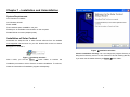
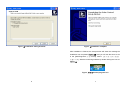
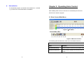
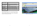
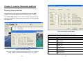
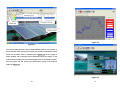
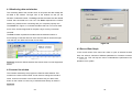
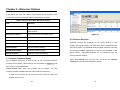
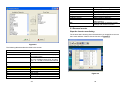
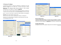
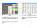
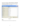
Table of Contents
Solar Control Program - User Manual
Designed for MPI Series Grid-Tie Inverters
Chapter 1 - Installation and Uninstallation................................ 2
Chapter 2 - Operating Solar Control......................................... 9
2.1 Solar Control Main Menu ............................................ 9
2.2 Communication Setting ............................................. 12
2.3. Interface location...................................................... 15
Chapter 3 - Inverter Parameter and Data............................... 16
Chapter 4- Basic Operation.................................................... 19
4.1 Monitoring Data and Window .................................... 22
4.2 Inverter list window ................................................... 22
4.3 Record Data Graph ................................................... 23
4.4 Inverter Data Setup................................................... 24
Chapter 5 - Menu bar Options................................................ 26
5.1 Inverter Command Setup .......................................... 26
5.2 Channel Selection..................................................... 27
5.3 Remove Inverter ....................................................... 29
5.4 System Configure ..................................................... 30
5.5 Inverter Data Setup................................................... 33
5.6 Record Review.......................................................... 34
5.7 Event Review ............................................................ 38
5.8 E-Mail Setup ............................................................. 40
5.9 GSM Modem Setup .................................................. 41
1
Chapter 1 - Installation and Uninstallation
System Requirements
CPU: Pentium II 533MHz
OS: Win2000, WinXP
RAM: 128MB
Free hard disk space: 550MB for one year
RS232 port: An available communication on the computer
RS485-RS232 converter (adapter power)
Installation of Solar Control
Download the Setup.exe file of Solar Control software from the website
www.mppsolar.com and save it in your PC. Double click on the icon shown
as Figure 1-1 to install it.
Figure 1-2 Installation windows
Choose installation directory: You can change the program directory by
filling the full directory name in or click “Browse” to find an existing directory.
Figure 1-1 Pre-Setup windows
If you want use the default directory as Figure 1-3 Click <Next>.
After a while, you will see Figure 1-2 Press <Next> to continue the
installation processes or clicks <Cancel> to exit the installation. To continue,
follow the instructions of installation program subsequently.
2
3
Figure 1-3 Program directory windows
Figure 1-4 Program Folder windows
Name the program: You can change, add or use default program name as
Installation confirmation: Confirm the setting of the installation as
showing in Figure 1-4 .After entering all the information, click “Next”.
Figure 1-5. If you want to modify information of previous steps, just click
<Back> to modify the settings. Click <Next> to start the installation.
4
5
Figure 1-5 Installation setting windows
Figure 1-6 Installation complete
After installation is finished, the setup window will show the message that
installation has completed (Figure 1-6), and you will see the short-cut icon
in the [Start/Programs/ Solar Control] menus. The Solar control display in
window bottom. Start the monitoring software by double clicking the icon as in
Figure 1-7.
Figure 1-7 Solar Control program icon
6
7
z
Uninstallation
To uninstall the program, just double click uninstall icon, “Uninstall
Chapter 2 - Operating Solar Control
Solar Control.exe” in the same folder of Installation.
After installing Solar Control, locate its icon or the desktop shortcut and
double-click to start the program.
2.1 Solar Control Main Menu
Figure 2-1 Main Menu
Control Menu Bar
(1)
(2)
(3)
(4)
(5)
(6)
(7)
(8)
(9)
Figure 2-2 Menu bar function
The following table introduces the main menu and toolbar shortcuts.
Table 2-1 Solar Control Main Menu and Toolbar
8
Field
Definition
(1)Command Setup
Click this button to check the connected inverter
(2)Channel Selection
Click this button displays the channel for the current
inverter
9
(3)System Configure
Click this button to setup the com port and sampling
time
(4)Inverter Data Setup
Click this button to setup inverter parameters
(5)Record Review
Click this button generate a graph of the current
inverter data
(6)Event Review
Click this button change the event settings
(7)E-mail Setup
Click this button to mail the inverter message
(8)GSM Modem Setup
Click this button to send the inverter message
(9)Chosen Button
Click this button to chose the inverter and setting
Monitoring framework
Before use the software, please check the communication interface address
setting, the maximum address is up to 255 units, currently connected
inverters are displayed in the main window on startup. The following figure
displays the root list populated with inverters.
10
Figure 2-3 monitoring overview
11
For more detailed information please refer to the RS485 card’s manual.
2.2 Communication Setting
Every inverter is equipped with a serial port. Directly connect your inverter to your
PC via a serial cable and the Converter (RS485-RS232) and setup the baud rate
9600 on the corresponding devices.
Connection Troubleshooting
If the main window is empty then no inverter is detected. Please see the following
procedure:
Multi- Connection via Converter
(1)RS232 Connection
Connect a converter via the RS485 card to the corresponding to your inverter.
•
The default settings of Solar Control are already optimally configured for most
equipment. It is recommended that these settings with exception to the Com
Port remain unchanged. To display or edit these settings please see Serial
Communication Settings.
Check the cable connections between inverter and computer. Make sure
both ends are well connected.
•
Make sure there is no card in the RS485 expansion slot as it disables
communication with RS232.
(2)RS485 Connection
Serial Communication Settings
•
Check the RS485 card on each inverter is inserted correctly.
To configure Solar Control serial (RS232) or USB connection, click System
Configuration from the menu bar, click on Setup of Connection Setup, and
then select COM port or USB.
•
Check the connection between inverters. The four wires on each terminal
blocks (R+, R-, T+, T-) are fully secured.
•
Check the wire connections on the RS485-to-RS232 converter. The
terminals (R+, R-, T+, T-) on RS485 card must be connected to (T+, T-, R+,
R-) respectively on the converter as the following table displays.
Note★ Hardware wiring and RS485 settings★
RS485 interface uses a higher voltage than RS232, and therefore it is
recommended for use over long distances between inverters and PC.
Table 2-2 Interface Exchange
There are four pins in a RS485 Modbus card, T+, T-, R+, and R-. If you want to
link each inverter by a four-wire cable, be sure to make the correct connections.
RS485-to-RS232
converter
The inverters interface card
The function also supports the half-duplex(R+,T+); the system could integrate the
temperature or irradiance meter.
R+
T+
R-
T-
T+
R+
T-
R-
You can also link each inverter via the telephone line (recommended).
Connecting multiple PV Inverters
If you want to connect multiple inverters, the optional RS485 card (optional) for
each inverter is required. The RS485 card allows connection of multiple
inverters in series. The first inverter connects your computer via an
RS485-to-RS232 converter. The next inverter connects to the RS485 card of
the first inverter. Subsequent inverters are daisy chained in the same fashion.
12
(3)Check the COM PORT settings in Solar Control are correct.
(4)Select “command setup” to address the connections to your inverters or
sensors.
13
The record contain limit
Select recording contain limit for your PC memory.
Real time sampling
Select interval sampling time for real time display.
Select language
Click to language setting.
Cancel
Click this button to exit the current window without
saving.
Ok
Click this button to save your settings and exit the
current window.
2.3. Interface location
This section is used to communicate with other PC; the RS232 interface is
located behind the protection cover. Open this covers by screwdriver as figure
below.
The pin definition is
Figure 2-4 Communication Setting
The following table describes the fields in this screen.
Table 2-3 Communication Settings
Field
Definition
Com Port
Select Com Port connected from your PC.
Baud rate
9600 or 19200 ( the interface card jump pin define)
Message setup
Click to enable other program when failure
detected.
Report data setup
Click to setup the time for the report data and
e-mail in the folder.
Display data setup
Click to written the message in graphic block.
14
Pin
1
2
3
4
5
6
7
8
9
Assignment Description
N.C.
TxD
RxD
N.C.
Common
N.C.
N.C.
N.C.
N.C.
*N.C. means “No Connection”
15
Chapter 3 - Inverter Parameter and Data
Adjusting inverter parameters
The parameters of each inverter can be adjusted remotely with Solar
Control. In the Chosen Button select the desired inverter to change.
Click Inverter Data Setup in the main menu and then enable the function,
and key in the password “administrator” then enter ”ok” into the parameter
settings window.
Figure 3-2 Parameter setting status
The following table describes the parameters in this screen.
Table 3-1 Parameter Setting
Parameter
Vpv-Start(V)
T-Start(Sec)
Vac-Min(V)
Vac-Max(V)
Fac-Min(V)
Figure 3-1 Parameter Setting
When into the setting window, the parameter value can be modified by
setting .after key in the new value please enter “ok” the bottom.
16
Fac-Max(V)
Zac-Max(mOhm)
Definition
This is the voltage required to start the inverter.
This is the time delay between reconnecting to the grid. (i.e.
after a fault)
This is the minimum voltage that the inverter maintains grid
connection.
This is the maximum voltage that the inverter maintains grid
connection.
This is the maximum frequency that the inverter maintains
grid connection.
This is the maximum frequency that the inverter maintains
grid connection.
This is the maximum impedance that the inverter maintains
grid connection
17
Dzac(mOhm)
This is the maximum rate of change of impedance allowed
by the inverter to maintain grid connection.
Chapter 4- Basic Operation
To avoid accidental alteration of parameter settings, a password is
required. To obtain this password please contact your local dealer.
Main Frame
After starting the Solar Control, the main frame as Figure 4.1 prompts. The
top of the main frame is MENU bar where user can operate this program by
selecting the items and sub-items. In the status window is the inverter list
serial number where the detected inverters connected to computer are
listed and showing the real status by green/red/yellow symbols.
Once the program started, it will search Inverters connected to the
computer automatically. In the mean time, Solar Control will make a
registration with each inverter. There will be a “registration number”
between the software and each of the inverter. The registration number will
not be changed even you “remove” the inverter from the list.
18
19
Figure 4.2
Figure 4.1
The inverter status window could be extend friendly when more inverters on
the list window. After selecting an inverter, the inverter could setup the alias
name and real-time chart in monitoring bar Figure 4.2. On the upper of
status window, the monitoring data of selected inverter are listed; on the
chart of the monitoring bar, the real-time graph such as AC power is shown.
And the graphic bar will showing the photovoltaic system CO2 emission
totally as Figure 4.3
Figure 4.3
20
21
4.1 Monitoring data and window
The monitoring data of the inverters such as AC power and DC voltage are
all listed in the window. The light color of the window can tell you the
situation of selected inverter. The Gray indicates the status that the related
inverter was connected but is not now. The Green represents the inverter
without any problem and is connecting with your computer properly now.
The Yellow as in Figure 4.1 indicates the status that one or more non-fatal
errors of the inverter happened for the past 2 days, but they have been
removed.
The Red condition represents the status that the selected inverter is
encountering a Fault and does not work. After the fault is cleared, the light
color will turn into Yellow and remain for two days.
Figure 4.5
4.3 Record Data Graph
In the record review of the menu bar, there is a plot of selected channel.
User can select 9 channels of different parameters or inverters to observe
Figure 4.4
Figure 4.4 shows the Yellow situation that means some error has happened
as Figure 4.6. This can help the user to understand the performance and
problems of his system.
before.
4.2 Inverter list window
The inverters detected by the program are listed in status window. This
number is the name of the inverter. If user wants to change the inverter’s
name, choose one inverter in the list first, double click your left mouse
button on the number or name, key in desired name directly as shown in
Figure 4.5.
22
23
Instantaneous
graph
Figure 4.6
Figure 4.7
4.4 Inverter Data Setup
If you want to investigate more detail information of inverters, just select the
inverter in the status window and click the inverter data setup of the menu
bar.
The information full view window, which includes all the data of inverters as
Figure 4.7, will prompt.
24
25
Chapter 5 - Menu bar Options
In the MENU bar, user can explore more functions of this program. Each
function and meaning in the main frame is described as following:
Table 5-1 Solar Control Main Menu and Toolbar
Field
Definition
(1)Command Setup
Set up the conditions of connection.
(2)Channel Selection
Setting the parameter channel showing in
status window
(3)System Configure
setup the com port and sampling time
(4)Inverter Data Setup
setup inverter parameters
(5)Record Review
generate a graph of the current inverter data
(6)Event Review
change the event settings
(7)E-mail Setup
mail the inverter message
(8)GSM Modem Setup
send the inverter message
25 channels available, suggestion from which 8 are displayed on the
(9)Chosen Button
Chose the inverter and setting
status window.
Figure 5.1
5.2 Channel Selection
Available inverters are displayed on the status window on that
displays the inverter identity and fields that contain information about
the internal status. The displayed fields are called channels. There are
Displayed channels can be customized with the
channel selection window.
5.1 Inverter Command Setup
The connection menu bar is used to set up the connection between
Select one Inverter from the main bar, and then click Channel
selection to view the channel selection options.
computer and inverters. Three functions can be utilized as Figure 5.1, and
each function is described below:
Check Inverter Join: when new inverters join the system. The new
inverters will easy to address and the status window will showing.
In case some inverters are not found in the list, user may check the
address correct or not.
26
27
Pac
Zac
E-Total
h-Total
Temperature
Temperature sensor
Irradiance sensor
Cancel
OK
Power supplied to the grid
Grid impedance
Total energy supplied to the grid
Total operating hours
Inverter internal temperature
Solar module outdoor temperature
Solar irradiance detection
Click this button to close this window
without saving.
Click this button to save the current
settings and close this window.
5.3 Remove Inverter
Stop the inverter monitoring
The inverter status showing disconnected when you would like to remove
the inverter address. Please click the function as Figure5.3.
Figure 5.2
The following table describes the fields in this screen.
Table 5-2 Inverter Channels
Field
Available Channels
>
<
>>
<<
Move up
Available Channels
Vpv1
Ipv1
Iac
Vac
Fac
Definition
This field lists the channels that display on
the inverter status.
Select a channel in the Selected Channel
list or the Available Channel list, and then
click < or > to add or remove that channel.
Add or remove all channels
channels ranking in the overview
PV1 voltage
PV1 current
Grid current
Grid voltage
Grid frequency
28
Figure 5.3
29
5.4 System Configure
Connect Solar inverter to a computer: via RS485. To configure this, click the
System Configure from the Menu Bar, a window will prompt as below
Figure 5.4. The message Setup could be setting for other program
executed when error happen, the setting as Figure 5.5.
The next step is to find the serial communication port where the COM Port
connected. Click the Setup button of Connection Setup. Select the proper
port in “Com Port” sub-menu and leave the other selection unchanged as
Figure 5.4, the communication setup is done.
Select the sub-menu and then sampling time Setting. To change the
Figure 5.6
Figure 5.7
frequency of recording samples, change the value (seconds) in the “Real
Time Sampling Interval” field.
Report Data Setup
The record data format setting is a function that is operated by qualified service
personnel. This function is used to change the display format of inverter. Once it is
selected, the data will appear as Figure 5.6 and be found in setting file folder.
Display Data Setup
Message information list in graphic display and CO2 emission as Figure 5.8.
Figure 5.4
Figure 5.5
30
31
The following table describes the fields in this screen.
Table 5-3 sampling Setting
Field
Message Setup
Time show
Definition
Setting error message setup, when error happen the
message will alarming the user and operating some
program.
Report data setup
Sampling interval
Figure 5.8
Tex or Excel format showing update, minimum time >1
sec.
Daily report data
XML or Excel format to folder, please setup the time.
Report File path
Enable the record function to file data.
Enable e-mail report Setting which time to delivery the mail.
Enable SMS report
Setting which time to delivery the SMS.
Real Time Sampling Interval
(1~60) Seconds Enter the delay in seconds between data record entries.
Display data setup
Message showing in Message information list in graphic display and CO2
graphic display
emission parameter key in.
History Data Sampling Interval
Daily
Select the period in seconds to display the Daily history
graph.
Monthly
Select the period in hours to display the Monthly history
graph.
Weekly
Select the period in minutes to display the Weekly
history graph.
Yearly
Select the period in hours to display the Yearly history
graph.
Click this button to close this window without saving.
Cancel
Click this button to save the current settings and close
OK
this window.
5.5 Inverter Data Setup
The Parameter setting is a function that is operated by qualified service
personnel. This function is used to change the operational parameters of
inverter. Once it is selected, the password window will appear as Figure 5.9
for prevention of unauthorized change:
32
33
select Record review and then Setup. Then to setup the Show Type to
plot inverter data over a specified period. The following graphs displays the
historical parameters output to the grid according to a time interval set in
the graphic display screen. The display color setup of framework could be
adjusted by clicking the right mouse bottom.
Figure 5.9
Follow the instruction to enter the correct password, if wrong password is
entered, it will show the message: Incorrect Password! To get the password,
please contact with local service agent.
Note: To prevent unexpected operation, it is necessary to enter the
password before operation. Please contact with local agent if necessary.
Reset E-Total and h-Total
Figure 5.10
The function for reset E-Total (accumulated energy) or h-Total (total
operation time) of specific inverter. Select one inverter first and click this
The following table describes the buttons in this window, showing as the
option from the Inverter Data Setup as in Figure 5.9.
Figure5.11.
Table 5-4 Record Review
5.6 Record Review
To display the data history graph for an inverter, first select the inverter’s
serial number in the right Box as Figure5.10. Now go to the main bar and
34
Button
Setup
Save
View Date
Definition
Click this button to show graphic display type
Click this button to save the file for the data or image
Click the Browser to setup the date period
35
Figure 5.12
Figure 5.11
In some cases, users may want to save the data transfer to excel file so
that it is easier to analysis. The data in the windows will be saved to another
Data and Image Review
file. The file format is a common format called XML which can be opened by
All monitoring data of inverters are automatically saved in the folder after
MS EXCEL. In this function could easy to edit the inverter data for any type
starting Solar Control, these file could only be seen in the window when
as Figure 5.13.
save to files.
For the inverter you are interested to investigate, you can select the inverter
from the 9 channels, select the inverter and parameters of data in each
browser, choose the date and click the button “save” to load the data in this
file Figure 5.12.
36
37
Figure 5.13
5.7 Event Review
Figure 5.14
Whenever the error and/or fault of inverters occur, the records are kept in
The data in the windows will be saved to another file. The file format is a
one file. To check the file contents, click Event review in the menu bar, a
common format called XML which can be opened by MS EXCEL. In this
window prompt as (Figure 5.14) can list the error history. This error history
function could easy to edit the inverter data for any type as Figure 5.15.
can help user to find some clues that inverter stopped. For further analysis,
user can also save the record in XML file. He may send this file to his dealer
to check if inverter does not function smoothly.
Figure 5.15
38
39
5.8 E-Mail Setup
In case of a user wants to get report of the inverter, he may set up the time
and events he wants to get the report. Check the Report Type as Routine
and Warning to determine the moment and events to notice as Figure 5.17.
When Routing is checked, the report will be sent according to time entered
every day as Figure 5.18, the time setting is in System Configure below”
enable mail report timed”. When Warning is checked, the report will be
sent once any of the warning events listed in occurs. In the same manner,
when error is checked, the report will be sent in any event listed in Figure
5.16
Figure 5.17
Figure 5.18
We suggest not checking Warning except it is necessary. During the
operation, it may quite frequent that warning events occur every day.
There are three ways to send report: Storing to a File, Sending a SMS from
GSM module, and Sending an E-mail. Choose the way by checking the
options, fill in the file name and location to be stored, GSM number to get
the report, or the email addresses where the report are going, the report will
be sent according to the selection. Please indicate the Mail Server to send
the report by Email Figure 5.16. To know the Mail Server, please contact
with local ISP (Internet Service Provider) for further information.
5.9 GSM Modem Setup
In case of a user wants to get SMS of the inverter status, he may set up the
time and events he wants to get the report. Check the Report Type as
Warning to determine the moment and events to notice as Figure 5.19.
Figure 5.16
When Routing is checked, the report will be sent according to time entered
40
41
every day, the time setting is in System Configure below” enable SMS
report timed”. When Warning is checked, the report will be sent once any
of the warning events listed in occurs. In the same manner, when error is
checked, the report will be sent in any event listed.
Figure 5.19
Help
The contents of help documents. Study this once any problem found.
42