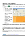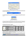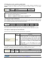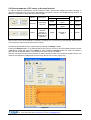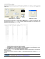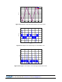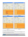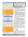
1
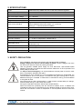
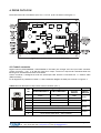
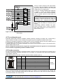
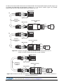
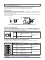
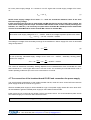
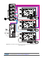
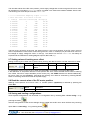
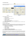
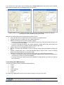
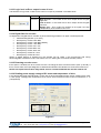
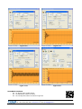
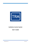
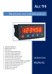
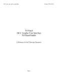
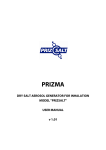
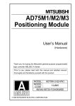
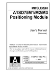
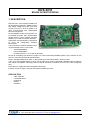
DCS-3010
BRUSH DC MOTOR DRIVE
1. DESCRIPTION
DCS-3010 is a microcontroller PWM drive
for permanent magnet DC (PMDC) motors
with supply voltage up to 100 V DC and
current up to 30 A. Drive is based on a
16-bit microcontroller with implemented
PID control algorithm.
As the feedback of DC motor position an
incremental encoder with phase-shifted
square signal is used. Encoder interface
enables 1x, 2x and 4x encoder resolution.
Adjustment of all parameters is performed
by using the configuration software
ServoTune3.
The input control interface enables control
via opto-isolated lines in next modes:
- STEP/DIR/ENABLE,
- CW/CCW/ENABLE,
- Encoder follower in 1x, 2x and 4x decoding,
as well as via analog input within the range 0–5 V with and without feedback (there is the connector on the
drive for connecting an external potentiometer).
Build-in soft start enables DC motor 1s after powering on decreasing electric shock on start.
There is an opto-isolated output on drive named Track Error which is activated if adjusted value of tracking
error offset is exceeded. That output can be used for activation of external circuit for DC motor emergency
stop.
Drive has over-voltage and over-temperature protection.
If electric current is higher, drive can be placed on additional cooler.
APPLICATION
-
CNC machines
Coordinate tables
Positioning
Robots
Education
Prizma doo, Kumanovska str. 8, 34000 Kragujevac, Serbia
Tel. +381 34 330 200, web: www.prizma.rs e-mail: [email protected]
Doc: DCS-3010 man Ver.1.07, January 2015. © by PRIZMA
Page 1 of 24
2. SPECIFICATIONS
Type
PWM closed loop PMDC Servo drive with PID controller algorithm
PWM frequency
10 ÷ 20 kHz, software set up
Number of axis
1
DC motor supply voltage
10 ÷ 100 V DC
DC motor current
3 ÷ 30 A max, software set up
Logic circuit power supply
18 ÷ 28 V DC / 200 mA
Input control interface
Digital control modes via opto-isolated lines STEP/DIR/ENA,
CW/CCW/ENA and Encoder follower (1x, 2x and 4x)
Analog 0 ÷ 5 V with and without feedback
Command line current
5 mA at 5 V
Output
Opto-isolated Track Error
Frequency of STEP command
< 600 kHz
Command line pulse width
> 0,5 µs
Feedback
Incremental encoder with phase-shifted square signal
Encoder resolution
×1, ×2 and ×4 multiplication, software set up
Encoder power supply
Source on drive +5 V DC / 250 mA
Parameter set up
Via IDC10 connector and programming interface (PI-RS232, IPI-USB or
Bluetooth BT-PI)
Build in protections
Over-voltage and over-temperature
Dimensions (W x L x H)
154 mm x 105 mm x 45 mm
Weight
~300 g
NOTE: specifications are subject to change without notice
3. SEFETY PRECAUTION
Drive installation can perform only person who has appropriate knowledge.
Supply voltages over 50 V DC can be danger of death. If supply voltage is over 50 V
DC, aluminium heat sink has to be properly grounded.
Use only galvanic isolated power supply for drive DCS-3010. Opto-isolated space
between input-output command lines and controller electronics on drive printed circuit
board (PCB) is around 5mm.
For stop in case of emergency it is recommended to interrupt power line of DC motor
and, if it is possible, activate motor brake.
o
If temperature on drive exceeds 70 C over-temperature protection will be activated. It is
recommended for drive to be placed in enclosures with good cooling and to ensure
additional cooling if it is needed. In case when it is used fan for cooling, recommendation
is using filter for dust.
Drive should not be used in places where, in case of failure, people safety is in danger,
financial losses are big, or there exist other losses.
During drive operation should be used all required precautious.
Does not exclude the possibility that this document contains errors. In addition the
manufacturer assumes no responsibility for any damage caused by the use of this drive,
which has occurred as a result of compliance or non-compliance with this instruction
manual.
Prizma doo, Kumanovska str. 8, 34000 Kragujevac, Serbia
Tel. +381 34 330 200, web: www.prizma.rs e-mail: [email protected]
Doc: DCS-3010 man Ver.1.07, January 2015. © by PRIZMA
Page 2 of 24
4. DRIVE OUTLOOK
Drive DCS-3010 has 6 connectors (from Con. 1 to Con. 6) as it is shown in the figure 4.1.
Figure 4.1 Connector positions on drive DCS-3010
4.1 Control connector
Digital controls (STEP/DIR/ENA, CW/CCW/ENA or Encoder) are brought over the 8-pin RJ45 connector
(control connector – Con. 1) as well as Track Error output. Track Error output that is activated when the
tracking error exceeds the set value of the offset.
Control connector is designed so that the input-output card IO3-R2 is connected via 1-1 network cable
(Ethernet cable).
Pin arrangement is presented in Table 4.1, and a schematic diagram of these pins is shown in Figure 4.2.
Tabela 4.1 Pins description of 8-pin RJ45 control connector (Con.1)
8
Con.1
DCS-3010
1
1
8
Selected type of digital control
Pin
No.
STEP/DIR/ENABLE
CW/CCW/ENABLE
Encoder
follower
1
STEP –
CW –
GND
2
STEP +
CW +
A+
3
DIR -
CCW -
GND
4
DIR +
CCW +
B+
5
ENABLE – (GND)
6
ENABLE +
7
Error output (emitter)
8
Error output (Track Error – open collector)
Prizma doo, Kumanovska str. 8, 34000 Kragujevac, Serbia
Tel. +381 34 330 200, web: www.prizma.rs e-mail: [email protected]
Doc: DCS-3010 man Ver.1.07, January 2015. © by PRIZMA
INPUT /
OUTPUT
Input 1
Input 2
Input 3
Output 1
Page 3 of 24
There is a 680 Ω resistor at the optocouplers
for STEP, DIR and ENABLE command, that
limits the current to 5mA at the command
voltage of 5V (TTL logical level).
If the logic command voltage at the entrances
is higher, it should be placed additional
resistors at lines 2, 4 and 6 and at connector
Con.1 to ensure that the current does not
exceed 5 mA.
EXAMPLE: If the drive DCS-3010 is control
by using the PLC with 24VDC logic levels, it is
necessary in each of the lines 2, 4 and 6 to
the connector Con. 1 add the 3.9 kΩ resistor.
Here it is necessary to note that in line Track
Error should be placed an external pull-up
resistor.
Optoisolating distance between the inputoutput command lines of control connectors
and control electronics on the PCB drive is
approximately 5 mm.
Figure 4.2 Schematic representation of opto-isolated inputs
and outputs
4.2 The configuration port
Parameter setting (PID controller constants, encoder resolution, tracking error offset, etc.) is performed by
using PI-RS232, IPI-USB or PI-BT interface for programming and configuration software ServoTune3.
Programming interfaces PI-RS-232, IPI-USB or PI-BT can be connected to the DC servo drive DCS-3010 via
the configuration port marked as Con.2 in Figure 4.1 (10-pin IDC connector).
A detailed description of the setup parameters of DC servo drive DCS-3010 is given in the instructions for
use the software ServoTune3.
NOTE: Configuration port ground is not galvanic separated from the drive ground. It is recommended
to use insulation programming interface IPI-USB or PI-BT.
4.3 Encoder connector
For DC motor position feedback incremental encoder is used on DC servo drive DCS-3010. Encoder can be
connected via encoder connector (connector Con.3 in Figure 4.1). Functions of the 8-pin RJ45 connectors
are provided in Table 4.2.
Table 4.2 Description of encoder connector pins 8-pin RJ45 connector (Con.3)
8
Con.3
DCS-3010
1
1
8
Pin No.
Name
Description
Function
1
2
3
4
5
6
7
8
A+
AB+
BNC
NC
+Ve
GND
A encoder channel (pull-up resistor 4.7 kΩ)
A\ encoder channel
B encoder channel (pull-up resistor 4.7 kΩ)
B\ encoder channel
Encoder power supply source 5 V / 250 mA max
GND – Encoder
Encoder
connection
Use an incremental encoder with phase-shifted square TTL outputs. It is recommended to use encoder with
a minimum number of encoder pulses (lines) of 200 PPR. On the drive is the source of power supply for
incremental encoder +5V / 250 mA max.
Prizma doo, Kumanovska str. 8, 34000 Kragujevac, Serbia
Tel. +381 34 330 200, web: www.prizma.rs e-mail: [email protected]
Doc: DCS-3010 man Ver.1.07, January 2015. © by PRIZMA
Page 4 of 24
On the DC servo drive DCS-3010 can be connected encoder with single-ended outputs (A and B, Figure 4.3)
or encoder with differential (complementary) outputs (A+, A-, B+ and B- outputs, Figure 4.4). Encoder
interface SED1 at the A and B inputs has pull-up resistors of 4.7 kΩ.
DCS-3010
1
a)
8
Con.3
8p8c (RJ45)
Encoder interface
SED1
8p8c (RJ45)
GND B A +5V
1
8
GND
B
A
+5V
GND
B
A
+5V
encoder
Shilded
network cable
Cat 5e
DC
motor
DCS-3010
1
b)
8
Con.3
Shilded
network cable
Cat 5e
8p8c (RJ45)
Encoder interface
DD1
8p8c (RJ45)
1
8
encoder
GND
GND
BB+
AA+
+5V
B
A
+5V
DC
motor
Figure 4.3 Connection of single-ended encoder with DC servo drive DCS-3010 via,
a) SED1 encoder interface and b) DD1 encoder interface
DCS-3010
1
8
Con.3
8p8c (RJ45)
Oklopljeni
mrežni kabl
Cat 5e
Enkoder interfejs
DD1
8p8c (RJ45)
1
8
GND
BB+
AA+
+5V
GND
BB+
AA+
+5V
Figure 4.4 Connection of encoder with differential (complementary) outputs via DD1 encoder interface on
DC servo drive DCS-3010
Prizma doo, Kumanovska str. 8, 34000 Kragujevac, Serbia
Tel. +381 34 330 200, web: www.prizma.rs e-mail: [email protected]
Doc: DCS-3010 man Ver.1.07, January 2015. © by PRIZMA
Page 5 of 24
NOTE: Connection of single-ended encoder on DC servo drive DCS-3010 via DD1 encoder interface
is not recommended for larger cable lengths.
In order to reduce or eliminate the impact of high-frequency electrical noise is recommended to use shielded
network cable Cat 5e for connection encoder interface SED1 or DD1 with DC servo drive.
Cable to connect the encoder should not be longer than a specific application requires.
4.4 Analog input
DC servo drive DCS-3010 has the ability to control DC motor via the reference voltage of 0÷5 V which is
applied to the analog input connector (Con. 4 in Figure 4.1).
External potentiometer with nominal resistance of 1÷10 kΩ can be directly connected at the analog input
connector as shown in Figure 4.5.a.
Figure 4.5.b the connection of external motion path generator. Voltage at the motion path generator output
should not exceed 5 V DC.
Figure 4.5 Voltage reference analog input DC servo drive DCS-3010 generated over,
a) external potentiometer and b) motion path generator
4.5 Logic circuit power supply
Logic circuit power supply of drive DCS-3010 is performed via a connector Con.5 (see Figure 4.1). Logic
circuit supply voltage should be from 18÷28 V DC / 200 mA. It is not necessary that this source to be
stabilized; it is enough that after rectification apply electrolytic capacitor with minimum capacitance 470 µF.
Table 4.3 Description of pins (terminals) in the 2-pin connector Con. 5
DCS-3010
Name
1
+VL
1 2
Con.5
Pin No.
2
GND
Description
Power supply +18÷28V DC /
200mA
Function
Logic circuit power
supply
GND
4.6 DC motor power supply and connection for DC motor
DC motor power supply and connection for DC motor is located on the connector Con. 6 (Figure 4.1).
Table 4.4 Description of pins (terminals) of connector Con. 6
Pin No.
Name
1
GND
Description
Function
Ground
3
DC motor power
supply
2
+Vmot
2
4
DCS-3010
3
M1
+10÷100 V DC
DC motor terminal
1
Connecting DC motor
4
M2
DC motor terminal
Prizma doo, Kumanovska str. 8, 34000 Kragujevac, Serbia
Tel. +381 34 330 200, web: www.prizma.rs e-mail: [email protected]
Doc: DCS-3010 man Ver.1.07, January 2015. © by PRIZMA
Page 6 of 24
DC motor power supply voltage Vmot should be 10÷15% higher than nominal supply voltage of DC motor,
i.e.:
Vmot = 1,15 ⋅ U n
(1)
NOTE: Power supply voltage of DC motor Vmot must not exceed the maximum value of the drive
DCS-3010 supply voltage.
If after connecting the DC motor to terminal M1 and M2 and after the arrival of the supply voltage, the
motor starts rotating, and then stops and OP/ER LED indicator starts to flash 2 times (Tracking error
indicator; see Table 6.1), it is necessary to replace motor terminals M1 and M2 (DC motor terminal M1
connect to terminal M2 and DC motor terminal M2 connect to terminal M1).
EXAMPLE:
Nominal DC motor supply voltage DC is U n = 48VDC . What is the voltage required to power a DC motor?
Vmot = 1,15 ⋅ U n = 1,15 ⋅ 48 = 55,2VDC ≈ 55VDC
Calculating the voltage of the secondary windings of the transformer used to supply DC motor is calculated
using the expression:
U sek = 1,2 +
Vmot
1,41
(2)
EXAMPLE:
For the previously calculated supply voltage of DC motor Vmot = 55DVC , secondary winding power
transformer voltage is:
V
55
U sek = 1,2 + mot = 1,2 +
= 40,2VAC ≈ 40VAC
1,41
1,41
The current of transformer secondary winding depends on the characteristics of the connected DC motor
and it should be 50 ÷ 100% higher than motor’s nominal current. It is necessary to know that the DC motor in
certain operating modes can pull much more current than it is nominal.
4.7 The connection of the breakout board IO3-R2 and connection the power supply
The recommended configuration of the breakout board IO3-R2, three DC servo drives DCS-3010 and the
power supply DCS-3010, is shown in Figure 4.6.
Galvanic isolated power supply is recommended for Logic circuit power supply of each DC servo drive DCS3010 and addition galvanic isolated power supply for the breakout board IO3-R2.
Power supply for DC motors can be carried out from one power source. It is recommended to place a slow
blow fuse on supply line +Vmot for each drive DCS-3010.
NOTE: Take care not to create a ground loop while system installation.
Prizma doo, Kumanovska str. 8, 34000 Kragujevac, Serbia
Tel. +381 34 330 200, web: www.prizma.rs e-mail: [email protected]
Doc: DCS-3010 man Ver.1.07, January 2015. © by PRIZMA
Page 7 of 24
Figure 4.6 The connection of the breakout board IO3-R2 with 3 DC servo drives DCS-3010 and
power supply circuit
Prizma doo, Kumanovska str. 8, 34000 Kragujevac, Serbia
Tel. +381 34 330 200, web: www.prizma.rs e-mail: [email protected]
Doc: DCS-3010 man Ver.1.07, January 2015. © by PRIZMA
Page 8 of 24
5. RESET BUTTON
RESET button is placed between configuration port Con.2 and connector for encoder Con.3 (see Figure 4.1).
By pressing the RESET button it is possible to cancel the present error of DC servo drive.
In addition, pressing the RESET button performs the disable of output H-bridge, so it is possible to rotate the
rotor of DC motor without disconnection of supply voltage.
6. LED INDICATORS
There are 2 LED indicators on the drive as follows:
- multifunctional red OP/ER LED indicator and
- red LED indicator Imax shows exceeding the maximum set current DC motor.
Table 6.1 Description of the state multifunctional OP/ER LED indicator
OP/ER
Description
The control electronics is not under voltage
Drive ready to start – ENABLE
1x
Errors
Drive ready to start – DISABLE
2x
Tracking error
3x
Encoder error
Description
-
4x
Over-temperature protection is activated *
5x
Over-voltage protection **
6x
Circuits for setting the level of the maximum current error
Error of microcontroller
-
7x
Action needed
Increase the value of Error offset
Press the RESET button
Check the condition of the encoder and
encoder cable
Turn off error detection of encoder
Press the RESET button
Provide better cooling of the drive
Press the RESET button
Provide a source with the lower voltage
for DC power supply
Press the RESET button
Contact the authorized service
Press the RESET button
Contact the authorized service
o
* The limit of activation over-temperature protection is set at 70 C.
** The limit of activation over-voltage protection is set at 120 VDC.
WARRANTY
Manufacturer guarantees that all DC servo drives DCS-3010 will work in proper upon delivery. Before
delivery all DC servo drives DCS-3010 are tested on power supply voltage with connected DC motor in
range of 20÷90 VDC and output current up to 20A. Supply voltage which that exceeds the maximum allowed
value, incorrectly connected power supply, incorrectly connected and defective DC servo motor, strong
electromagnetic discharge (close to contactor) etc. can damage the drive.
Prizma doo, Kumanovska str. 8, 34000 Kragujevac, Serbia
Tel. +381 34 330 200, web: www.prizma.rs e-mail: [email protected]
Doc: DCS-3010 man Ver.1.07, January 2015. © by PRIZMA
Page 9 of 24
9. ServoTune3 – INSTRUCTIONS MANUAL
To adjust the parameters of drive DCS-3010 use the configuration software ServoTune3 (Figure 9.1). The
software consists of a single file and to install it is necessary to copy the file to the desired folder on your
computer.
The configuration software
operating system.
ServoTune3 will works on Windows XP, Windows Vista or Windows 7
Software ServoTune3 enables:
•
Adjusting
the
PID
controller
constants,
•
Adjusting the encoder resolution
multiplication,
•
Adjusting the steps multiplier,
•
Enable/disable of drive DCS-3010,
•
Setting the number of steps to
capture the response of DC motor
on step function and drawing
diagrams of the motor position
response, diagram of voltage and
current change,
•
Adjusting values of Tracking error
offset,
•
Read the current value of the
position of DC servo motor,
•
Recording of log file with the values
of set position, current position
difference and values of the DC
motor electric current,
•
Selection of input interface type
(STEP/DIR/ENA,
CW/CCW/ENA,
encoder 1x, 2x or 4x or analog input
with and without feedback),
•
Selection of PWM frequency,
•
Setting options of digital filter for
encoder input,
•
Setting the maximum electric current
through DC motor etc.
Figure 9.1 ServoTune3
NOTE: Software ServoTune3 is used for adjustment of working parameters of drive DCS-3010. This
software is not appropriate to control DC motor.
9.1 COM port selection
Connection between software ServoTune3 and PC with drive DCS-3010 is achieved via programming
interfaces PI-RS232, IPI-USB or PI-BT. Setting parameters for the COM port is done through dialogue from
the Figure 9.2 which is accessed by selecting option File -> Communication setup or by pressing the icon
.
Set the serial number of the COM port that is connected to the interface for programming as well as the
desired baud rate. If check box 'Save to EEPROM' is activated, selected value of baud rate will be recorded
in microcontroller EEPROM.
Prizma doo, Kumanovska str. 8, 34000 Kragujevac, Serbia
Tel. +381 34 330 200, web: www.prizma.rs e-mail: [email protected]
Doc: DCS-3010 man Ver.1.07, January 2015. © by PRIZMA
Page 10 of 24
Figure 9.2 Communication setup dialog
At the ServoTune3 application top will appear label that the drive is online with version of firmware (Figure
9.3) if communication between PC and drive is established. From drive DCS-3010 all parameters will be read
and printed in the appropriate fields.
Figure 9.3
In the case that communication is not achieved with the drive DCS-3010, after starting software ServoTune3
warning dialog will appear, as it is shown in Figure 9.4 and servo offline status in main window, as it is shown in
Figure 9.1.
Figure 9.4 Error opening COM port
This error occurs when the parameters are not set up correctly (number of COM port and baud rate) or when
the programming interface is not connected to the drive. In some cases, may occur a breakdown in
communication with the drive DCS-3010 and then it is necessary shut down the ServoTune3 software,
restart the drive DCS-3010 by pushing RESET button and start the ServoTune3 software again.
9.2 Setting the PID controller constants
Drive DCS-3010 is based on the 16-bit RISC microcontroller with PID control algorithm in it. Setting these
constants is performed in fields that are shown in the table below.
Name
Description
Minimum
Maximum
Default
Kp
Proportional gain constant
0
32768
50
Ki
Integral gain constant
0
32768
0
Kd
Derivative gain constant
0
32768
0
Pressing the button Get from EEPROM values for Kp, Ki and Kd will be read. To write new values in
EEPROM microcontroller, it is necessary to press the Set button.
NOTE: During setting PID constants take all precautions as it may cause oscillation in DC servo
motor – machine mechanics system.
Prizma doo, Kumanovska str. 8, 34000 Kragujevac, Serbia
Tel. +381 34 330 200, web: www.prizma.rs e-mail: [email protected]
Doc: DCS-3010 man Ver.1.07, January 2015. © by PRIZMA
Page 11 of 24
9.3 Setting the encoder resolution multiplication
Drive DCS-3010 has the capability of software adjustment for encoder resolution multiplication. So it is
possible to encoders with relatively small number of pulses per revolution to obtain 2 or 4 times higher
resolution.
Name
Description
Values
Enc
Encoder resolution multiplication
x1, x2 and x4
EXAMPLE:
Encoder with resolution 500PPR (pulses per revolution) will have:
•
500PPR for encoder multiplication 1x,
•
500PPR x 2 = 1000PPR for encoder resolution multiplication 2x and
•
500PPR x 4 = 2000PPR for encoder resolution multiplication 4x.
9.4 Setting the steps multiplication
Steps multiplicator shows how many steps do the DC servo motor for each pulse on the STEP command
line. This parameter is useful in the case of using the high-resolution encoder, but STEP command generator
has no possibility of generating pulses of sufficiently high frequency.
Name
Description
Step multiplier
Step multiplication
Minimum
Maximum
Default
1
50
1
To write desire values in EEPROM microcontroller, it is necessary to press the Set button.
NOTE: Higher values for the step multiplier can lead to unsmooth movement, especially at low speed.
9.5 Control of enable input on drive DCS-3010
Options for control of drive DCS-3010 enable input are shown in Table below.
Name
Alternatives
Enable
control
Software controlled – In this mode ENABLE input at control
connector Con.1 (Figure 4.1) is activated. If there is logical
unit at the ENABLE input, the drive is active and will carry out
the commands that come from STEP and DIR command
lines. In the case that at ENABLE input is logic zero then the
drive DCS-3010 is disabled, commands STEP and DIR are
not carried out and DC motor is not under voltage (this option
is often used if it is necessary to manually rotate the DC
motor).
Always enable – In this mode ENABLE input at control
connector Con.1 (Figure 4.1) is not activated. Drive is always
activated (enabled).
From software ServoTune3 can be performed selection of ENABLE mode of drive DCS-3010 during setting
parameters. The change of check box can be performed by pressing the function key F2.
Name
Description
Drive
Enable
Drive
Enable
Options
ENABLE – selected (DC servo motor is under voltage)
DISABLE – not selected (DC servo motor is not under voltage)
Prizma doo, Kumanovska str. 8, 34000 Kragujevac, Serbia
Tel. +381 34 330 200, web: www.prizma.rs e-mail: [email protected]
Doc: DCS-3010 man Ver.1.07, January 2015. © by PRIZMA
Page 12 of 24
9.6 Record response of DC motor to the step function
In order to adjust the parameters of PID controllers easier, ServoTune3 software provides the ability to
record the response of DC servo motor and attached mechanics to which is connected to a step function. In
addition, it is possible to set a desired number of steps.
Name
Description
Sampling
Recording
response
Steps
Performing a
desired
number of
steps without
recording the
response
Parameters
Min
Max
Number of
steps
1
32767*
Samples
Number of read
values
1
32767
Steps
Number of
steps
1
32767*
Name
Description
Steps
* Maximum value of Steps should be lower than set value of Error offset. Otherwise tracking error will appear
and DC servo motor will be disabled. Cancelling of tracking error is performed by pressing the RESET button
or by switching off the DCS-3010 drive power supply.
Activate the appropriate function is performed by pressing the Sample or Run.
Pressing the Sample button, or by pressing the function key F3, DC servo drive will handle the given number
of Steps. By setting the check box For/Rev for each pressing of Sample button DC motor will handle a
given number of step alternately in one and then the other direction of rotation.
After the execution of Sample command will be drawn diagrams of DC motor response at step function, and
charts of the changes of voltage and current through the DC servo motor (Figure 9.5).
Figure 9.5
Prizma doo, Kumanovska str. 8, 34000 Kragujevac, Serbia
Tel. +381 34 330 200, web: www.prizma.rs e-mail: [email protected]
Doc: DCS-3010 man Ver.1.07, January 2015. © by PRIZMA
Page 13 of 24
The recorded values of the DC motor position, power supply voltage and current through the DC servo motor
will be saved in a file called odziv.dat which is located in the folder that contains software ServoTune3.
The following is a small sample of the file odziv.dat.
% ****** ServoTune sampling output ********
% Date and time: 07.12.2012 07:27:39
% Time[s] Position Current[mA] Voltage[V]
0.000000
0
244
26.63
0.001500
1
488
27.12
0.004000
9
1220
26.13
0.006500
26
1464
24.65
0.009000
48
1953
25.15
0.011500
76
2441
22.19
0.014000
111
2685
24.65
0.016500
152
2685
23.67
0.019000
200
3173
22.68
0.021500
254
3417
20.71
0.024500
315
3906
24.16
0.027000
396
4150
22.68
0.029500
471
4394
20.71
0.032000
553
4638
20.21
The first column of the file is the time, the second column is the current position of the DC motor, the third
column represents the value of the current through the DC motor in milliamps (mA) and the fourth column is
the change of supply voltage DC motor in volts (V). The values from the file odziv.dat can easily be
imported into the software for drawing diagrams (Excel, MATLAB, i.e.).
9.7 Setting values of tracking error offset
Setting of tracking error offset can be performed by entering the desired values in a field named Error offset.
Name
Description
Error offset
Tracking
offset
Error
Minimum
Maximum
Recommendation
0
32767
bigger than 100
To save desire values of tracking error offset into EEPROM it is necessary to press the Set button.
If the difference of set position and the current position DC servo motor exceeds the set value of tracking
error offset, Track Error output activates (to the control port), and OP/ER indicator will denote Additionally,
DC servo motor will be DISABLED. Cancelling the tracking error offset is achieved by pressing RESET
button or switching off the drive DCS-3010 power supply.
9.8 Read the current value of the DC motor position
Reading current position of DC servo motor, i.e. encoder position (mposition) is obtained by pressing the
button Get.
Name
Description
mposition
Current position of DC servo motor
9.9 Saving and loading configurations
Once adjusted configurations can be saved in a configuration file by selecting File -> Save config... or by
.
pressing the button
Also the configuration file with all the settings can be loaded into the DC servo drive DCS-3010 by choosing
option File -> Load config... or by pressing button
.
Prizma doo, Kumanovska str. 8, 34000 Kragujevac, Serbia
Tel. +381 34 330 200, web: www.prizma.rs e-mail: [email protected]
Doc: DCS-3010 man Ver.1.07, January 2015. © by PRIZMA
Page 14 of 24
9.10 Advanced Setup
Pressing the button Adv. Setup (Figure 9.6) or icon
advanced settings (Figure 9.7).
opens dialog box with a choice of options for
Figure 9.6
Figure 9.7
Advanced settings include the range of options:
•
type of input interface,
•
frequency of PWM,
•
the logic level at Error output in case of error,
•
digital filter for encoder,
•
encoder error detection,
•
password protection of parameters,
•
selection of parameters that will be shown in the main diagram and
•
maximum current of DC motor.
In order to accept change of any of the above values in the EEPROM microcontroller it is necessary to press
the button OK (Figure 9.7).
9.10.1 Type of Input interface
Control of DC motor is carried out through three command lines. The first two command lines in this manual
called STEP/DIR, while the third is ENABLE (see Figure 4.2). Optional input interface provides a choice of
control modes via the above three command lines, or via the analog inputs in the following modes:
•
Step/Direction i.e. STEP/DIR/ENABLE,
•
StepUp/StepDown i.e. CW/CCW/ENABLE,
•
Encoder x1 /ENABLE,
•
Encoder x2 /ENABLE,
•
Encoder x4 /ENABLE,
•
Analog input with feedback (Analog with FB) and
•
Analog input without feedback (Analog without FB).
NOTE: Configuration of input interface type Encoder 1x, 2x and 4x are not fully tested.
DC servo drive DCS-3010 has the ability to control DC motor via the voltage signal of 0÷5V which is applied
to the analog input (Con. 4 in Figure 4.1). At the analog input can be directly connected potentiometer with
nominal resistance 1÷10kΩ (Figure 4.5.a) or external motion path generator (Figure 4.5.b). Look section 4.4
of this manual.
Prizma doo, Kumanovska str. 8, 34000 Kragujevac, Serbia
Tel. +381 34 330 200, web: www.prizma.rs e-mail: [email protected]
Doc: DCS-3010 man Ver.1.07, January 2015. © by PRIZMA
Page 15 of 24
If you choose one of the options from the analog input, Analog option button will become active, and after
its activation will appear one of the dialogue shown in Figure 9.8.
a)
b)
Figure 9.8 Dialog box for setting parameters, a) analog input with feedback (Analog with FB) and
b) analog input without feedback (Analog without FB)
Dialog box for setting parameters of analog input provides a choice:
•
One or two directions of rotation of DC motor (Forward or Forward/Reverse),
•
Change the direction of rotation DC moror (Reverse direction),
•
Maximum Nmax and minimum Nmin revolution speed.
o In case of choosing the analog input with feedback (Analog with FB) values Nmax and Nmin are
in revolutions per minute (RPM).
o In case of choosing the analog input without feedback (Analog without FB) values Nmax and
Nmin are in percents (%) in relation to power voltage of DC motor.
•
Width of inactive zone (Threshold) expressed in mV.
•
Number of encoder lines (Encoder) in case of choosing analog input with feedback (Analog with
FB).
•
Options of disabled DC motor in case that adjusted speed is equal to zero in case of choosing
analog input without feedback (Analog without FB).
•
Parameters of acceleration (Acc) and slowing down (Dec) (Limit acceleration/deceleration).
o In case of choosing the analog input with feedback (Analog with FB) values Acc and Dec are in
revolutions per minute per one second (RPM/s).
o In case of choosing the analog input without feedback (Analog without FB) values Acc and Dec
are in second (s).
9.10.2 Setting the PWM frequency
This option provides the ability to adjust the PWM frequency:
•
10 kHz,
•
12 kHz,
•
14 kHz,
•
16 kHz (default),
•
18 kHz and
•
20 kHz.
For frequency of PWM bellow 20 kHz can be heard "whistling" coming from DC motor.
Prizma doo, Kumanovska str. 8, 34000 Kragujevac, Serbia
Tel. +381 34 330 200, web: www.prizma.rs e-mail: [email protected]
Doc: DCS-3010 man Ver.1.07, January 2015. © by PRIZMA
Page 16 of 24
9.10.3 Logic level on Error output in case of error
The selection of logic level in case of errors at Error output is presented in the table below.
Name
Option of choice – description
Error out
High on error – In the case of error Error output will be at logical
high level
Low on error – In the case of error Error output will be at logical
low level
Always low – Error output will always be at logical low level
independently of the existence of errors
9.10.4 Digital filter for encoder
An adjustment of digital filter for encoder is performed through selection of upper cut-off frequencies:
•
switched off digital filter (Turn OFF),
•
the frequency of filter 6.667 MHz,
•
the frequency of filter 3.333 MHz (default),
•
the frequency of filter 1.667 MHz,
•
the frequency of filter 416.7 kHz,
•
the frequency of filter 208.3 kHz,
•
the frequency of filter 104.2 kHz,
•
the frequency of filter 52.1 kHz i
•
the frequency of filter 26.0 kHz.
Option of digital filtering of signals from the encoder can be useful in the environment with strong
electromagnetic interference, which can lead to errors in reading the incremental encoder position.
9.10.5 Detecting encoder errors
If this option is enabled, the drive checks if there is a change at levels of both encoder inputs (A and B). If
this is not the case, the output stage will be disabled and OP/ER LED indicator will show the encoder error.
NOTE: This option has not been fully tested, and it is recommended that the checker remains off.
9.10.6 Reading power supply voltage of DC motor and temperature of drive
In the appropriate fields (framed fields in Figure 9.9) is performed reading power supply voltage of DC motor
o
in volts (Supp. Voltage) and temperature of DC servo drive DCS-3010 close to the microcontroller in C
(Temperature).
Figure 9.9
Prizma doo, Kumanovska str. 8, 34000 Kragujevac, Serbia
Tel. +381 34 330 200, web: www.prizma.rs e-mail: [email protected]
Doc: DCS-3010 man Ver.1.07, January 2015. © by PRIZMA
Page 17 of 24
9.10.7 Entering the password
The ServoTune3 software provides the ability to enter password to prevent unauthorized changes to the
parameters of DC servo drive DCS-3010.
In order to activate this option it is necessary to select a checker Enable password first as it is shown in
Figure 9.10 thereby Password and Retype become active and in them is then possible to enter the
password. When the password is entered then during each of the next start-up of ServoTune3 software and
the connection to the DC servo drive DCS-3010 dialog window (Figure 9.11) for the typing of password will
open, which becomes a requirement for approach settings.
Figure 9.10 Password dialogue
Figure 9.11 Password dialogue on ServoTune3
software startup
9.10.8 Selection of options of the main diagram
The part of dialogue in the advanced settings (Advanced setup) shown in Figure 9.12 (Sampling options)
allow choosing of:
•
What parameter will be shown in the main diagram and
•
The thickness of the diagram line that will be plotted (Thin, Medium and Thick).
Figure 9.12
9.10.9 Setting the maximum DC motor current
Over the slider shown in Figure 9.13 maximum current of DC motor is adjusted. The adjusted value is
readable in the appropriate field. Maximum current through DC motor can be adjusted in the range of 3÷30
A.
Figure 9.13
Prizma doo, Kumanovska str. 8, 34000 Kragujevac, Serbia
Tel. +381 34 330 200, web: www.prizma.rs e-mail: [email protected]
Doc: DCS-3010 man Ver.1.07, January 2015. © by PRIZMA
Page 18 of 24
9.10.9 LOG File recording
Recording of Log file with the values of present position and position error, as well as present current and
voltage at DC motor is activated by pressing the Log button (Figure 9.14) which opens the Loging dialog
(Figure 9.15).
Figure 9.14 Position of Log button
Figure 9.15 Log dialog
Start recording a log file activates by pressing Start and Stop recording by pressing this button again. Data
will be stored in a file called servo.log that is located in the same folder as the ServoTune3 software. The
following is a small part of the servo.log file.
% *********** ServoTune log output file ************
% Date and time: 07.12.2012 19:00:05
% Time[s]
Position PosDiff Current[mA] Voltage[V]
0.020960
-401
0
0
98.23
0.023580
-401
0
0
98.23
0.025676
-401
0
0
98.23
0.027772
-401
0
0
97.78
0.029868
-401
0
0
98.23
0.032488
-401
0
0
98.23
0.034584
-401
0
0
98.89
0.036680
-400
1
0
98.23
0.000000
-396
5
0
98.23
0.001572
-386
13
0
98.23
0.003668
-373
20
0
97.78
0.005764
-349
32
119
97.02
0.007860
-325
39
833
95.45
0.009956
-296
44
1310
94.02
0.012576
-263
39
1905
93.25
0.014672
-226
38
2381
92.15
At that:
•
•
•
The first column is time in seconds,
The second column is present position of DC motor,
The third column is position error (tracking error), i.e. difference between specified and current
position of DC servo motor is expressed in the steps,
•
The fourth column represents the value of the current through the DC motor expressed in mA and
•
The fifth column is supply voltage of DC motor expressed in V.
Data from file servo.log file can be easily loaded into any software for drawing and for further analysing.
(Excel, MATLAB etc.).
In Figures 9.16, 9.17 and 9.18 is shown an example of parameter changes from one recording servo.log
data file.
Prizma doo, Kumanovska str. 8, 34000 Kragujevac, Serbia
Tel. +381 34 330 200, web: www.prizma.rs e-mail: [email protected]
Doc: DCS-3010 man Ver.1.07, January 2015. © by PRIZMA
Page 19 of 24
100
zadato
set
actual
stvarno
80
60
40
odziv, mm
20
0
-20
-40
-60
-80
-100
0
2
4
6
vreme, s
8
10
12
Figure 9.16 Diagram of set and actual position of DC servo motor
0.2
0.15
greska, mm
0.1
0.05
0
-0.05
-0.1
-0.15
0
2
4
6
vreme, s
8
10
12
Figure 9.17 Diagram of the positioning error calculated in mm
1.4
1.2
struja, A
1
0.8
0.6
0.4
0.2
0
0
2
4
6
vreme, s
8
10
12
Figure 9.18 Diagram of the electric current through the DC servo motor
Prizma doo, Kumanovska str. 8, 34000 Kragujevac, Serbia
Tel. +381 34 330 200, web: www.prizma.rs e-mail: [email protected]
Doc: DCS-3010 man Ver.1.07, January 2015. © by PRIZMA
Page 20 of 24
10. PID CONSTANTS SETUP PROCEDURE
NOTE:
During setting of PID constants take all precautions as it may cause
oscillation of DC servo motor-mechanics.
When setting up start from low value of maximum current through the DC motor
during which should check the behaviour of DC motor. After this gradually
increase the set value of maximum DC motor current.
The values of the PID constants depend on:
• Characteristic of DC motor (moment of inertia, supply voltage, maximum electric current etc.),
• Physical characteristics of mechanics, which is connected at DC motor (mass, damping etc.),
• Resolution of the incremental encoder mounted on the DC motor,
• Selected encoder resolution multiplication (x1, x2 or x4), and
• Some other factors (ambient temperature, lubricant, etc.).
Adjusted PID constants are valid only for that configuration. If there is a change of configuration (some of the
above parameters) it is necessary to readjust the PID constants.
The following is a description of the adjustment of PID constants. Encoder resolution in this case is 500 PPR,
encoder resolution multiplication is x4, so that the overall encoder resolution is 2000 PPR.
STEP 1: Initial value of PID constants is:
• Proportional constant Kp = 50,
• Integral constant Ki = 0 i
• Derivate constant Kd = 0.
Slowly increase the constant Kp until you get response similar to the response shown in Figure 10.1.
STEP 2: Increase constant Kd until the system response is not "calm" as is shown in Figure 10.2. The
constant Kd may be significantly larger than the constant Kp.
STEP 3: Gradually increase the constants Kp and Ki to the response as shown in Figure 10.3. Here it should
be noted that the constant Ki is much smaller compared to the other two constants.
Repeat steps 2 and 3 to the point where the shaft of DC motor behaves as "locked“. Also check the
motor running at various revolution speeds (must not occur oscillation and vibration during
operation).
STEP 4: Final values of the PID constants and the response of the motor are shown in Figure 10.4.
It is necessary to check determined PID constants during the work of the machine and, if it is necessary, to
correct them.
Prizma doo, Kumanovska str. 8, 34000 Kragujevac, Serbia
Tel. +381 34 330 200, web: www.prizma.rs e-mail: [email protected]
Doc: DCS-3010 man Ver.1.07, January 2015. © by PRIZMA
Page 21 of 24
Figure 10.1
Figure 10.2
Figure 10.3
Figure 10.4
10.1 Automatic adjustment of PID parameters
The auto-configuring and adjusting PID parameters is available from ServoTune3 software version v3.07.
The dialog for automatic adjustment of PID parameters opens by pressing button AutoPID (Figure 10.5).
This will display a warning dialog shown in Figure 10.6.
Prizma doo, Kumanovska str. 8, 34000 Kragujevac, Serbia
Tel. +381 34 330 200, web: www.prizma.rs e-mail: [email protected]
Doc: DCS-3010 man Ver.1.07, January 2015. © by PRIZMA
Page 22 of 24
NOTE: Method for automatic adjustment of PID
constants involves bringing DC servo drive – DC
servo motor system and mechanical equipment
in an unstable state, so it is necessary to
mention that the system will oscillate.
Setup procedure of PID parameters in this
way the user performs at own risk.
Figure 10.5
Figure 10.6
Figure 10.7
Within AutoPID dialog, which is shown in Figure 10.7.,
it is possible to set the following parameters:
- Proportional constant Kp.
- Number of Steps to define the step function. Pulldown menu provides a choice of predefined values
for the number of steps: 100, 150, 200, 250, 300,
400, 500, 750 and 1000. Choose one value of the
number of steps corresponding to approximately 510% of the number of steps required to DC motor
make a full circle.
EXAMPLE: Encoder has 500PPR and selected
the option Encoder multiplier x4. In this case it
is necessary 500 x 4 = 2000 steps to the DC
motor make a full revolution. Recommended
values for Steps would be 100, 150 or 200.
- The duration of the measurement of Recording
time that can be selected via the pull-down menu:
1s, 2s, 3s, 4s and 5s. Whereas during the
recording system response required bringing the
system into oscillation it is recommended that this
time be as short as possible.
- Alternately reversing DC motor when recording
step
function
(option
Forw/Rev).
It
is
recommended that this option should be active.
- Option Enable drive only while sampling. It is
recommended that this option should be active.
The process of automatic adjustment of the of PID
constants involves gradually increasing the constant
Kp. With every change of constants Kp, it is necessary
to press the Sample (F3) or function key F3 to record
the system response. The parameter Kp is increased
gradually and gently, until it comes to the appearance
of the oscillation of the system, such as that shown in
Figures 10.8, 10.9 and 10.10. It is important to note
that in these figures are not shown all the steps in
gradual increasing of the parameter Kp.
ServoTune3 software will recognize that there is a
system oscillation, as is shown in Figure 10.10
(Oscillation is detected ...) and will suggest PID
controller constants Kp, Ki, and Kd according to the
given criteria. There is a choice of the following
criteria:
- Aggressive,
- Normal or
- Less aggressive.
Pressing the OK button (Apply) calculated PID
parameters will be stored in EEPROM microcontroller.
Check the behaviour of DC servo motor according PID
parameters calculated on this way (Figure 10.11).
If necessary, perform manual fine tuning of PID
parameters.
Prizma doo, Kumanovska str. 8, 34000 Kragujevac, Serbia
Tel. +381 34 330 200, web: www.prizma.rs e-mail: [email protected]
Doc: DCS-3010 man Ver.1.07, January 2015. © by PRIZMA
Page 23 of 24
Figure 10.8
Figure 10.9
Figure 10.10
Figure 10.11
DOKUMENT REVISION:
-
Ver. 1.0, January 2014., English version
Ver. 1.01, March 2014., Minor corrections
Ver. 1.07, January 2015., Minor corrections in Figure 4.6
Prizma doo, Kumanovska str. 8, 34000 Kragujevac, Serbia
Tel. +381 34 330 200, web: www.prizma.rs e-mail: [email protected]
Doc: DCS-3010 man Ver.1.07, January 2015. © by PRIZMA
Page 24 of 24