1
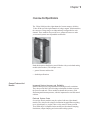
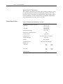
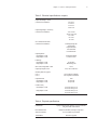
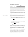
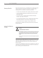
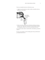
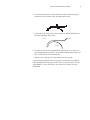
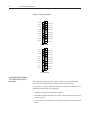
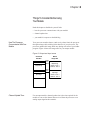
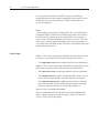
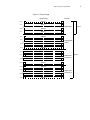
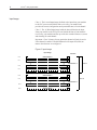
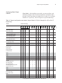
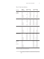
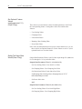
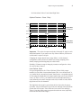
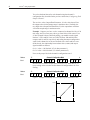
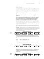
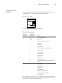
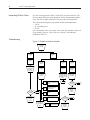
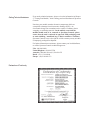
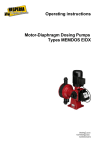
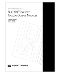
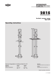
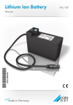
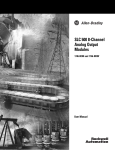
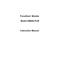
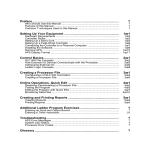
Preface
Read this preface to familiarize yourself with the rest of the owner’s
guide. This preface covers:
• who should use this guide
• what this guide covers
• related Allen-Bradley documents
• terms & abbreviations you should know
Who Should Use This Guide
Use this guide if you design, install, program, or maintain a control system
that uses Allen-Bradley Small Logic Controllers.
You should have a basic understanding of SLC 500 products. You should
also understand electronic process control and the ladder program
instructions required to generate the electronic signals that control your
application. If you do not, contact your local Allen-Bradley representative
for the proper training before using these products.
What This Guide Covers
Related Allen-Bradley
Documents
This guide covers the 1746sc-NO8i and 1746sc-NO8v analog output
modules. It contains the information you need to install, wire, use, and
maintain these modules. It also provides diagnostic and troubleshooting
help should the need arise.
Table 1 lists several Allen-Bradley documents that may help you as you
use these products.
vi
SLC 500™ Analog Output Modules
Table 1. Related Allen-Bradley documents
Allen-Bradley Doc. No.
Title
1747-2.30
SLC 500 System Overview
SGI-1.1
Application Considerations for Solid State Controls
1770-4.1
Allen-Bradley Programmable Controller Grounding and Wiring
Guidelines
1747-6.2
Installation & Operation Manual for Modular Hardware Style
Programmable Controllers
1747-NI001
Installation & Operation Manual for Fixed Hardware Style
Programmable Controllers
1747-6.15
Allen-Bradley SLC 500 Instruction Set Reference Manual
ABT-1747-TSG001
SLC 500 Software Programmers’s Quick Reference Guide
1747-NP002
Allen-Bradley HHT (Hand-Held Terminal) User Manual
1747-NM009
Getting Started Guide for HHT (Hand-Held Terminal)
SD499
Allen-Bradley Publication Index
AG-7.1
Allen-Bradley Industrial Automation Glossary
To obtain a copy of any of the Allen-Bradley documents listed, contact
your local Allen-Bradley office or distributor.
Terms & Abbreviations You
Should Know
You should understand the following terms and abbreviations before using
this guide. For the definitions of terms not listed here, refer to AllenBradley’s Industrial Automation Glossary, Publication AG-7.1
Channel – Refers to one of the sets of signal interfaces available on a
module’s terminal block.
Channel update time – For analog outputs, the time required for the
channel to convert the data received from the processor to analog output
signals at the terminals.
Chassis – See rack.
Configuration word – Contains the channel configuration information
needed by the module to configure and operate each channel. Information
is written to the configuration word through the logic supplied in your
ladder program.
D/A – Refers to digital-to-analog conversion. The conversion produces an
analog output signal whose magnitude is proportional to the digital value.
Data scaling - The data format that you select to define the logical
increments of the channel data word.
Preface
vii
Data word – A 16-bit integer that represents the value of the analog
output channel. The channel data word is valid only when the channel is
enabled and there are no channel errors.
LSB (least significant bit) – The bit that represents the smallest value
within a string of bits. The “weight” of this value is defined as the fullscale range divided by the resolution.
Module ID code – A unique number associated with each 1746 I/O
module. The code defines for the processor the type of I/O or specialty
module residing in a specific slot in the 1746 chassis.
Module update time – See channel update time.
Overall accuracy – The worst-case deviation of the signal over the full
range, expressed in percent of full scale.
Rack – A hardware assembly that houses devices such as I/O modules,
adapter modules, processor modules, and power supplies.
Repeatability – The closeness of agreement among repeated
measurements of the same variable under the same conditions.
Resolution – The smallest detectable change in a measurement, typically
expressed in engineering units (e.g. microseconds) or as a number of bits.
For example, a 16-bit system has 65536 possible output states. It can
therefore measure 1 part in 65536. See also effective resolution.
Status word – Contains status information about the channel’s current
configuration and operational state. You can use this information in your
ladder program to determine whether the channel data word is valid.
Step response time – The time required for the output signal to reach
95% of its expected, final value, given a full-scale step change in the
output data word.
viii
SLC 500™ Analog Output Modules
Contents
Preface ........................................................................................................................... v
Who Should Use This Guide ............................................................................................................................... v
What This Guide Covers ..................................................................................................................................... v
Related Allen-Bradley Documents ...................................................................................................................... v
Table 1. Related Allen-Bradley documents ........................................................................................................ vi
Terms & Abbreviations You Should Know ........................................................................................................ vi
Overview And Specifications........................................................................................ 1
General Features And Benefits ............................................................................................................................ 1
Detailed Specifications ........................................................................................................................................ 2
Table 2. Electrical specifications—module ......................................................................................................... 2
Table 3. Electrical specifications—outputs ......................................................................................................... 3
Table 4. Physical specifications........................................................................................................................... 3
Table 5. Environmental specifications ................................................................................................................ 4
Installing And Wiring Your Module ............................................................................. 5
Avoiding Electrostatic Damage ........................................................................................................................... 6
Determining Power Requirements....................................................................................................................... 6
Setting The Jumper J4 ......................................................................................................................................... 7
Selecting A Rack Slot .......................................................................................................................................... 8
Inserting Your Module Into The Rack ................................................................................................................. 8
Wiring Your Module .......................................................................................................................................... 10
Labeling And Re-Installing The Terminal Block (if it is removed) .................................................................. 12
Things To Consider Before Using Your Module ........................................................ 13
How The Processor Communicates With Your Module ................................................................................... 13
Channel Update Time ........................................................................................................................................ 13
Your Module’s Response To Slot Disabling...................................................................................................... 14
Channel Configuration, Data, and Status .................................................................... 15
Entering Your Module’s ID Code ..................................................................................................................... 15
Output Image ..................................................................................................................................................... 16
Input Image ........................................................................................................................................................ 18
Configuring Each Output Channel .................................................................................................................... 19
Set Optional Feature Values (Class 3 Only) ...................................................................................................... 22
Setting The Output Data Words (Class 3 Only) ................................................................................................ 22
Optional Features - (Class 3 Only) .................................................................................................................... 23
User-Defined Scale ............................................................................................................................................ 23
Output Clamping ............................................................................................................................................... 25
Set Limit Alarm Values ..................................................................................................................................... 26
Set Ramping / Rate Limiting Values ................................................................................................................. 27
Set Preset Fault Value ........................................................................................................................................ 28
Channel’s Configuration And Status (Class 1 and 3) ........................................................................................ 31
Chanel Input Status Word 2 (Class 3 Only) ..................................................................................................... 34
Ladder Logic Sample......................................................................................................................................... 36
Testing Your Module ................................................................................................... 37
Inspecting Your Module .................................................................................................................................... 37
Disconnecting Prime Movers ............................................................................................................................ 38
Powering Up ...................................................................................................................................................... 38
Interpreting The LED Indicators ....................................................................................................................... 39
Interpreting I/O Error Codes.............................................................................................................................. 40
Troubleshooting ................................................................................................................................................. 40
Maintaining Your Module And Ensuring Safety ........................................................ 41
Preventive Maintenance .................................................................................................................................... 41
Safety Considerations ........................................................................................................................................ 41
Declaration of Conformity .......................................................................................................................... xxxvii
Chapter 1
Overview And Specifications
The 1746sc-NO8i provides eight channels of current outputs, while the
1746sc-NO8v provides eight channels of voltage outputs. In both modules,
the current or voltage ranges are independently configurable for each
channel. These modules also provide new, advanced features to make
your control systems more dependable and flexible.
Read this chapter to familiarize yourself further with your isolated analog
module (shown above). This chapter covers:
• general features and benefits
• detailed specifications
General Features And
Benefits
Increased System Accuracy and Reliability
Both modules provide 8 output channels with a high usable resolution.
They also provide 500 Vdc field-wiring-to-backplane isolation to protect
the processor and rack. These modules maintain their accuracy with
fluctuating ambient temperatures, which is important for crowded control
cabinets.
Reduced System Costs
Several low-density modules may be replaced with one eight channel
module. They also provide a single-slot solution for applications requiring
up to eight outputs, so you don’t have to buy more I/O than you need.
Your ladder logic is simplified as the module provides channel ramping,
limit alarms, output clamping, and various data scaling options.
2
SLC 500™ Analog Output Modules
State-of-the-Art Performance
These modules incorporate proprietary Allen-Bradley technology, so they
operate and perform like the latest Allen-Bradley products. They also
provide 16-bits of resolution, user-programmable range settings, requires
no field calibration, software configuration, programmable output limits,
and programmable safe states in case of a fault.
Detailed Specifications
Table 2. Electrical specifications—module
Backplane Current Consumption (maximum)
1746sc-NO8i
1746sc-NO8v
Optional External 24V supply
Backplane Power Consumption (typical)
120 mA @ 5 Vdc
250 mA @ 24 Vdc
120 mA @ 5 Vdc
160 mA @ 24 Vdc
+24V +/-10%
5.6 W
Number Of Channels
8 single-ended
I/O Chassis Location
Any 1746 I/O module slot except slot 0
A/D Conversion Method
Calibration
Opto-Electrical Isolation
Module ID Code
1746sc-NO8i
1746sc-NO8v
Thermal Dissipation
Sigma-Delta
Factory calibrated
500 Vdc field wiring-to-backplane
3527
12727
Class 1
Class 3
3528
12728
Class 1
Class 3
6.6 W
Chapter 1: Overview And Specifications
Table 3. Electrical specifications—outputs
Output Current Ranges—NO8i
(selectable for each channel)
4 to 20 mA
0 to 20 mA
0 to 21 mA
0 to 21.5 mA
Output Voltage Ranges—NO8v only
(selectable for each channel)
-10 to +10 Vdc
-10.25 to +10.25 Vdc
0 to 10 Vdc
0 to 5 Vdc
1 to 5 Vdc
SLC Communication Formats
(selectable for each channel)
Scaled engineering units
Scaled for PID
Proportional counts
1746-NO4 format
User-defined scale
Output Impedance
Current Outputs—NO8i
Voltage Outputs—NO8v
Greater than 1 Mohm
Less than 1.0 ohm
Load Range
Current Outputs—NO8i
Voltage Outputs—NO8v
0 to 500 ohm
1Kohm and greater
Max. Current, Voltage Mode—NO8v
10 mA
Output Step Response Time
1 ms (0–95% of full scale)
Channel Update Time (typical)
Class 1
Class 3
5ms to update all 8 channels
10ms to update all 8 channels
Output Resolution
Current Outputs—NO8i
Voltage Outputs—NO8v
16-bit
366 nA/count
320 µV/count
Overall Accuracy
Current Outputs—NO8i
0.1% of full scale @ 25 °C
0.2% of full scale @ 60 °C
0.1% of full scale @ 25 °C
0.2% of full scale @ 60 °C
Voltage Outputs—NO8v
Table 4. Physical specifications
LED Indicators
Eight green channel status indicators, one for each channel
One green module status indicator
Recommended Cable
Belden 8761 (shielded, twisted-pair) or equivalent
Wire Size (maximum)
Two 14–24 AWG wire per terminal
Terminal Block
Removable (supplied)
3
4
SLC 500™ Analog Output Modules
Table 5. Environmental specifications
Operating Temperature
0 to 60 °C (32 to 140 °F)
Storage Temperature
-40 to 85 °C (-40 to 185 °F)
Relative Humidity
Certifications
Hazardous Environment Classifications
5 to 95% non-condensing
UL/CUL and CE
Class I Division 2 Groups ABCD
Chapter 2
Installing And Wiring Your Module
Read this chapter to install and wire your module. This chapter covers:
• avoiding electrostatic damage
• determining power requirements
• setting the external power jumper
• selecting a rack slot
• inserting your module into the rack
• wiring your module
Note that although your module has a jumper in the center of it’s printed
circuit board, this jumper is for the manufacturer’s use only. Also, your
module was calibrated by the manufacturer, so you don’t need to perform
this task.
Important - For UL and CUL compliance, power and input/output (I/O)
wiring must be in accordance with Class I, Division 2, wiring methods
[Article 501-4 (b) of the National Electrical Code , NFPA 70] and in
accordance with the authority having jurisdiction. Also, you must observe
the warnings shown below. Failure to observe these warnings can cause
personal injury.
WARNING
!
EXPLOSIONHAZARD
Substitution of components may impair suitability for
Class I, Division 2;
When in hazardous locations, turn off power before replacing or wiring
modules;
Do not disconnect equipment unless power has been switched off or the
area is known to be non-hazardous.
6
SLC 500™ Analog Output Modules
The following documents contain information that may help you as you
install and wire your module:
• National Electrical Code, published by the National Fire Protection
Association of Boston, MA
• IEEE Standard 518-1977, Guide for the Installation of Electrical
Equipment to Minimize Electrical Noise Inputs to Controllers from
External Sources
• IEEE Standard 142-1982, Recommended Practices for Grounding of
Industrial and Commercial Power Systems
• Noise Reduction Techniques in Electronic Systems, by Henry W.
Ott; published by Wiley-Interscience of New York in 1976
Avoiding Electrostatic
Damage
Guard against electrostatic damage by observing the following precautions:
CAUTION
!
ELECTROSTATICALLYSENSITIVECOMPONENTS
• Before handling the module, touch a grounded object to
rid yourself of electrostatic charge.
• When handling the module, wear an approved wrist strap
grounding device.
• Handle the module from the front, away from the
backplane connector. Do not touch backplane
connector pins.
• Keep the module in its static-shield container when not
in use or during shipment.
Failure to observe these precautions can degrade the module’s performance
or cause permanent damage.
Determining Power
Requirements
The backplane of the SLC 500 system can provide both 5 Vdc and 24
Vdc power. The following table shows the maximum current consumed by
your module when using these power sources:
7
Chapter 2: Installing And Wiring Your Module
Table 6. Backplane current consumed
24 Vdc *
Catalog Number
5 Vdc
w/o ext. supply
w/ ext. supply
1746-sc-NO8i
120 mA
250 mA
0 mA
1746sc-NO8v
120 mA
160 mA
0 mA
* The 1746sc-NO8i and 1746sc-NO8v output modules can use an external 24 Vdc power supply to
reduce backplane loading. To use an external 24 Vdc power supply, you must set your module’s jumper
J4 as indicated in the following subsection. To comply with the U.L. regulation the external supply must
be rated N.E.C. Class 2.
Use Table 6 to calculate the total load on the system power supply. For more information, see the AllenBradley system Installation and Operation Manual.
Setting The Jumper J4
The 1746sc-NO8i and 1746sc-NO8v output modules have an external 24
Vdc power jumper, J4, giving you the option of using an external power
supply:
• With the jumper in the 1-2 Shorted position, the module draws all its
power from the backplane of the SLC system.
1
Rack
2
3
Ext.
• With the jumper in the 2-3 Shorted position, the module draws its 24
Vdc power from an external power source; however, the module still
draws its 5 Vdc power from the backplane.
1
Rack
2
3
Ext
The jumper, J4, is located in the bottom right corner of the module’s circuit
board next to the power supply.
Note: Before setting J4 all system power must be turned off. This
includes the rack power as well as the optional 24V external
supply.
Note: If the module is configured to use an external +24V supply, the
supply must be turned on for the module to operate. If the external +24V
supply is turned off, the module’s outputs will be turned off, and the
module’s processor will be reset until power is restored. The module’s
LEDs will blink the 24v failure blink code. See the error blink code
descriptions in the troubleshooting section of this manual
8
SLC 500™ Analog Output Modules
Selecting A Rack Slot
Three factors determine where you should install your module in the rack:
ambient temperature, electrical noise and Class1/3 operation. When
selecting a slot for your module, try to position your module:
• in a rack close to the bottom of the enclosure (where the air is cooler)
• away from modules that generate significant heat, such as 32-point
input/output modules
• in a slot away from ac or high-voltage dc modules, hard contact
switches, relays, and ac motor drives
• to use the advanced features of Class 3 operation the module must be
located in the local rack. A 5/02 or above CPU must be used.
• away from the rack power supply (if using a modular system)
Remember that in a modular system, the processor always occupies the
first slot of the rack.
Inserting Your Module Into
The Rack
!
CAUTION
POSSIBLEEQUIPMENTOPERATION
Before installing or removing your module, always disconnect power from the
SLC 500 system and from any other source to the module (in other words,
don’t “hot swap” your module), and disconnect any devices wired to the
module.
Failure to observe this precaution can cause unintended equipment operation
and damage.
When inserting your module into the rack, you do not need to remove the
supplied 18-position terminal block from the module. If, however, you do
remove the terminal block and use the write-on label to identify your
module’s location.
To remove the terminal block, unscrew the two retaining screws at the top
and bottom of the terminal block, and using a screwdriver or needle-nose
pliers, carefully pry the terminal block loose.
Chapter 2: Installing And Wiring Your Module
9
To insert your module into the rack, follow these steps:
1. Align the circuit board of your module with the card guides at the top
and bottom of the chassis.
Top and Bottom
Module Release(s)
Card
Guide
2. Slide your module into the chassis until both top and bottom retaining
clips are secure. Apply firm even pressure on your module to attach it
to its backplane connector. Never force your module into the slot.
Cover all unused slots with the Card Slot Filler, Allen-Bradley part number
1746-N2.
To remove your module, press the retaining clips at the top and bottom of
your module and slide it out.
10
SLC 500™ Analog Output Modules
Wiring Your Module
To wire the terminal block, you need:
• a philips or flat-blade screwdriver
• Belden 8761 (shielded, twisted pair) cable or equivalent
• Each terminal may hold up to two 14 gauge leads.
CAUTION
!
POSSIBLEEQUIPMENTOPERATION
Before wiring your module, always disconnect power from the SLC 500
system and from any other source to the module.
Failure to observe this precaution can cause unintended equipment operation
and damage.
Before wiring the terminal block, take some time to plan your system:
• Ensure that the SLC 500 system is installed in a NEMA-rated
enclosure and that the SLC 500 system is properly grounded.
• Ensure that the load resistance for a current output channel is less than
500 ohms.
• Ensure that the load resistance for a voltage output channel is greater
than 1 kohms.
• Route the field wiring away from any other wiring and as far as
possible from sources of electrical noise, such as motors, transformers,
contactors, and ac devices. As a general rule, allow at lease 6 in. (about
15.2 cm) of separation for every 120 V of power.
• Routing the field wiring in grounded a conduit can reduce electrical
noise further.
• If the field wiring must cross ac or power cables, ensure that they cross
at right angles.
To wire your module, follow these steps:
1 Determine the length of cable you need to connect a channel to its field
device. Remember to include additional cable to route the shield wire
and foil shield to their ground points.
2. At each end of the cable, strip some casing to expose the individual
wires.
3. Trim the exposed signal wires to 2 in. lengths. Strip about 3/16 in.
(about 5 mm) of insulation away to expose the end of each wire.
Chapter 2: Installing And Wiring Your Module
11
4. At one end of the cable, twist the shield wire and foil shield together,
bend them away from the cable, and apply shrink wrap.
5. At the other end of the cable, cut the drain wire and foil shield back to
the cable and apply shrink wrap.
Insulation
Black Wire
Clear Wire
6. Connect the wires to the terminal block and field device as shown in
the following figures and table. The recommended maximum torque is 5
in-lb (0.565 Nm) for all terminal screws.
7. Repeat steps 1 through 6 for each channel on your module.
A system may malfunction due to a change in its operating environment.
After installing and wiring your module, check system operation. See the
Allen-Bradley system Installation and Operation Manual for more
information.
12
SLC 500™ Analog Output Modules
Figure 2. Wiring diagrams
V Out 0
V Out 1
V Out 2
V Out 3
V Out 4
V Out5
V Out 6
V Out 7
ANL COM 0
ANL COM 1
ANL COM 2
ANL COM 3
ANL COM 4
ANL COM 5
ANL COM 6
ANL COM 7
+24 VDC
DC COM
1746sc-NO8v
I Out 0
I Out 1
I Out 2
I Out 3
I Out 4
I Out5
ANL COM 0
ANL COM 1
ANL COM 2
ANL COM 3
ANL COM 4
ANL COM 5
I Out 6
I Out 7
ANL COM 6
ANL COM 7
+24 VDC
DC COM
1746sc-NO8i
Labeling And Re-Installing
The Terminal Block (if it is
removed)
The supplied terminal cover has a write-on label. Using this label helps
ensure that the terminal block is installed on the correct module.
Once you have wired your module and properly labeled the terminal cover,
install the terminal block on your module:
1. Align the terminal block with the receptacle.
2. Insert the terminal block and press firmly at the top and bottom until it is
properly seated.
3. Screw in the two retaining screws on the top and bottom of the terminal
block.
Chapter 3
Things To Consider Before Using
Your Module
Read this chapter to familiarize yourself with:
• how the processor communicates with your module
• channel update time
• your module’s response to slot disabling
How The Processor
Communicates With Your
Module
Your processor transfers data to (and receives data from) the processor
through an image table residing in the data files of your processor. The
processor updates this image table once during each scan of your ladder
program. Figure 4 shows the image table for your output module.
Figure 3. Output and input scans
SLC 5/02-05
Data Files
Slot e
Module
Image Table
Output
Scan
Output Image
8 Words - Class 1
32 Words - Class 3
Output Image
Slot e
Input Image
Channel Update Time
Input
Scan
Input Image
8 Words - Class 1
16 Words - Class 3
For an output module, channel update time is the time required for the
module to convert the channel data received from the processor to an
analog output signal at the terminals.
14
SLC 500™ Analog Output Modules
Channel update time will vary depending on mode of operation and
features implemented:
Table 7. Channel update time (all channels)
Mode
Class 1
Class 3
Your Module’s Response To
Slot Disabling
Update Time
5 ms
10 ms
By writing to the status file in the modular SLC processor, you can disable
any chassis slot. Refer to your SLC programming manual for the slot
disable/enable procedure.
!
CAUTION—POSSIBLEEQUIPMENTOPERATION
Always understand the implications of disabling a module before using the
slot disable feature.
Failure to observe this precaution can cause unintended equipment
operation.
When you disable an output module’s slot, the module holds its outputs in
their last state in Class 1 mode. When you re-enable the output module’s
slot, the data that is in the processor image table is converted to an analog
output signal during the next scan. Slot disabling only affects enabled
channels. In Class 3 mode the output will go to its fault state, as
configured by the user, when the slot is disabled. See the “Set Output
Behavior Under Fault Condition” section in the next chapter.
Chapter 4
Channel Configuration, Data,
and Status
Read this chapter to:
• enter your output module’s ID code
• configure each output channel
• set the optional features
• control each output channel’s signal
• monitor each output channel
• check each output channel’s configuration and status
To use your module, you need:
• programming equipment
• Allen-Bradley RSLogix 500
Entering Your Module’s ID
Code
Before using your module, you must configure the slot your module is in by
entering your module’s ID code in RSLogix.
When using RSLogix simply select your module from the list of modules
on the system I/O configuration display to automatically enter the ID code.
With earlier versions of RSLogix you must manually enter the ID code.
To enter your module’s ID code, select “other” from the list of modules on
the system I/O configuration display, and enter your module’s ID code at
the prompt. The module ID code for your module is:
Table 8. Output module ID code
Catalog Number Module ID Code
1746sc-NO8i
3527 Class 1 Mode (8 inputs / 8 outputs)
12727 Class 3 Mode (16 inputs, 32 outputs)
1746sc-NO8v
3528 Class 1 Mode (8 inputs / 8 outputs)
12728 Class 3 Mode (16 inputs / 32 outputs)
16
SLC 500™ Analog Output Modules
If you perform the “READ IO CONFIG” option in your RSLogix
programming software the module is configured to the respective Class 1
mode if the power is cycled at the PLC if the module has not been
previously configured.
Note:
If your module was previously configured for Class 3 operation and you
perform READ IO CONFIG and your RSLogix software does not have
the NO8 in it’s I/O pick list, then your module will be set to operate in
Class 3 mode. The input and output words will be set to zero. This will
likely cause your SLC program to indicate errors upon downloading. To
correct this remove the NO8 module from the I/O configuration listre-add
it per the instructions above.
Output Image
Class 1 - The 8-word, output image (defined as the output from the SLC
processor to your module) represents the following for the NO8i/v.
•
The output data words control output signal levels for each channel.
Class 3 - The 32-word, output image (defined as the output from the SLC
processor to your module) represents the following for the NO8i/v.:
• The output data words control output signal levels for each channel.
• The configuration bytes replace configuration DIP switches on your
module. In your output module, each word configures one channel.
• The output data parameters 1 and 2 typically define low and high
values for items such as limit alarms and output clamping. Ramping
and preset output on fault only use output data parameter 1.
Refer to Figure 4 for addition information.
For more information on the user-defined scale, output clamping, limit
alarms, ramping, and preset output on fault see Setting The Optional
Feature Values, later in this chapter.
17
Chapter 4: Using Your Output Module
Figure 4. Output Image
Output Image
O:e.0
Channel 0
O:e.1
Channel 1
O:e.6
Channel 6
O:e.7
Channel 7
O:e.8
Channel 0
O:e.9
Channel 1
Function
Output Data
O:e.14
Channel 6
O:e.15
Channel 7
O:e.16
Channel 0
O:e.17
Channel 1
O:e.22
Channel 6
O:e.23
Channel 7
O:e.24
Channel 0
O:e.25
Channel 1
O:e.30
Channel 6
O:e.31
Channel 7
Class 1
Configuration
Output
Output Data
Parameter 1
Output Data
Parameter 2
Class 3
18
SLC 500™ Analog Output Modules
Input Image
Class 1 - The 8-word input image (defined as the input from your module
to the SLC processor) holds the data received by your module and
provides the status (configuration and operational state) of each channel.
Class 3 - The 16 Word input image holds the data (defined as the input
from your module to the SLC processor) holds the data of each channel
received by your module and also provides the extended feature set, status
and alarming for each channel
Important - Class 3 features for any particular channel will only be active
if the channel is enabled. Disabled channels will output 0V (0mA) no
matter what features are configured.
Figure 5. Input Image
Input Image
I:e.0
Channel 0 Status 1
I:e.1
Channel 1 Status 1
Function
Input Status 1
I:e.6
Channel 6 Status 1
I:e.7
Channel 7 Status 1
I:e.8
Channel 0 Status 2
I:e.9
Channel 1 Status 2
Class 3
Input Status 2
I:e.14
Channel 6 Status 2
I:e.15
Channel 7 Status 2
Class 1
19
Chapter 4: Using Your Output Module
Configuring Each Output
Channel
Class 3 Only - After installing your module, you must configure each
channel by setting bit values in each configuration word. Input words 8
through 15 of the input image file (addresses O:e.8 and O:e.15) configure
channels 0–7 respectively. Refer to Figure 4 for specific addressing.
Table 9. Channel configuration word details, Output Words 8-15 (O:e.8 through O:e.15) for Ch. 0-7
respectively
To select…
Use these bit settings...
15 14 13 12 11 10 9
8
7
6
5
4
Output channel disable
Output channel enable
±10 Vdc output range (-NO8v)
0-21 mA output Range (-NO8i)
1–5 Vdc output range (-NO8v)
4-20mA output range(-NO8i)
0–5 Vdc output range (-NO8v only)
0-20mA output range (-NO8i)
0–10 Vdc output range (-NO8v only)
N/A output range (-NO8i)
invalid
2
1
0
0
1
0
1746-NO4 compatible format
Engineering units
Scaled for PID
Proportional counts
User-defined scale
Invalid
Invalid
Invalid
Clear Parameter*
Set Parameter*
No Action
Set User Scaling Values
Set Clamping Values
Set Limit Alarm Values
Set Ramping / Rate Limiting Values
Set Preset Fault Values
Invalid
Invalid
Reset Output on Fault
Hold Output on Fault
Preset Output on Fault
Invalid
Latch Alarms
Reset Latched Alarms
3
0
0
0
0
1
1
1
1
0
0
1
1
0
0
1
1
0
1
0
1
0
1
0
1
1
1
0
0
0
0
1
1
1
1
0
0
1
1
0
0
1
1
0
0
1
1
0
1
0
1
0
1
0
1
0
1
0
1
1
1
*A configuration error will occur if these bits are set to 1 at the same time.
0
0
0
1
1
0
1
1
20
SLC 500™ Analog Output Modules
Output Channel Enable (configuration bit 0)
Use this bit to enable or disable a channel.
Output Range (configuration bits 1–2)
Use this bit field to configure the channel voltage or current output range
for the type of output device you have connected to the module.
Data Format (configuration bits 4–6)
Use this bit field to select one of the following formats:
• 1746-NO4 compatible format (the format used by the 1746-NO4)
• engineering units (mV or nA)
• scaled for PID (works with the SLC PID instruction)
• proportional counts (two’s complement binary)
• user-defined scale
These data formats and ranges are defined in the following table:
21
Chapter 4: Using Your Output Module
Table 10. Data format definitions
Selected
Output Range
Data Value (counts)
Min.
Max.
Corresponding Signal
Min.
Max.
1746-NO4Compatible
(See Note 1)
±10 V
0–10 V
0–5 V
1–5 V
0–20 mA
0–21 mA
4–20 mA
-32768
0
0
+3277
0
0
+6242
+32767
+32767
+16384
+16384
+31208
+32767
+31208
-10 V
0V
0V
+1 V
0 mA
0 mA
+4 mA
+10 V
+10 V
+5 V
+5 V
+20 mA
+21 mA
+20 mA
Engineering Units
±10 V
0–10 V
0–5 V
1–5 V
0–20 mA
0–21 mA
4–20 mA
-10250
-500
-500
+500
0
0
+3500
+10250
+10250
+5500
+5500
+20500
+21500
+20500
-10.25 V
-0.50 V
-0.50 V
+0.50 V
0.0 mA
0.0 mA
+3.5 mA
+10.25 V
+10.25 V
+5.50 V
+5.50 V
+20.5 mA
+21.5 mA
+20.5 mA
Scaled for PID
±10 V
0–10 V
0–5 V
1–5 V
0–20 mA
0–21 mA
4–20 mA
0
0
0
0
0
0
0
+16383
+16383
+16383
+16383
+16383
+16383
+16383
-10 V
0V
0V
+1 V
0 mA
0 mA
+4 mA
+10 V
+10 V
+5 V
+5 V
+20 mA
+21 mA
+20 mA
Proportional Counts
±10 V
0–10 V
0–5 V
1–5 V
0–20 mA
0–21 mA
4–20 mA
-32768
-32768
-32768
-32768
-32768
-32768
-32768
+32767
+32767
+32767
+32767
+32767
+32767
+32767
-10.25 V
-0.50 V
-0.50 V
+0.50 V
0.0 mA
0.0 mA
+3.5 mA
+10.25 V
+10.25 V
+5.50 V
+5.50 V
+20.5 mA
+21.5 mA
+20.5 mA
User-Defined
Scale
±10 V
0–10 V
0–5 V
1–5 V
0–20 mA
0–21 mA
4–20 mA
-10.25 V
-0.50 V
-0.50 V
+0.50 V
0.0 mA
0.0 mA
+3.5 mA
+10.25 V
+10.25 V
+5.50 V
+5.50 V
+20.5 mA
+21.5 mA
+20.5 mA
Data Format
(See note 2)
1 Provides direct compatibility with the 1746-NO4 module.
2 For the user-defined scale, the data in output data parameter word 1 and 2 determine the count limits. See
the next subsection, User-Defined Scale, for information on the User-Defined Scale data
format.
22
SLC 500™ Analog Output Modules
Set Optional Feature
Values
(configuration bits 7-11)
(Class 3 Only)
These bits are used to load the values from data parameter 1 and 2 into
the corresponding feature. Setting these values also enables most
features.
• User Scaling Values
• Clamping Values
• Limit Alarm Values
• Ramping / Rate Limiting Value
• Preset Fault Value
Note: Once the data parameters have proper values and bits 9-11 are set,
then set bit 8 (set optional feature) to set the feature or set bit 7 (clear
optional feature) to clear the feature.
Setting The Output Data
Words (Class 3 Only)
Output Data Parameter Words 1 and 2 of the output image file (addresses
O:e.16 through O:e.31 let you define either:
Output Data Parameter Word 1 (O:e.16-O:e.23)
· Set User Scaling Values: User Scale Low Value
· Set Clamping Values: User Clamping Low Value
· Set Limit Alarm Values: Limit Alarm Low Value
· Set Ramping/ Rate Limiting Values: Ramping Rate (0-3276.7
millivolts(milliamps)/second)
· Set Preset fault value
and
Output Data Parameter Word 2 (O:e.24-O:e.31)
· Set User Scaling Values: User Scale High Value
· Set Clamping Values: User Clamping High Value
23
Chapter 4: Using Your Output Module
· Set Limit Alarm Values: Limit Alarm High Value
Optional Features - Class 3 Only
O:e.16
Channel 0
O:e.17
Channel 1
O:e.22
Channel 6
O:e.23
Channel 7
O:e.24
Channel 0
O:e.25
Channel 1
O:e.30
Channel 6
O:e.31
Channel 7
Output Data
Parameter 1
Output Data
Parameter 2
Important – The values in output word pairs 16 through 31 apply to each
individual channel. If you want to use any of these features you must set
each channel’s output word pair.
Changing the output data format or range (Bits 1-6 of the channel
configuration word) will clear or disable user scaling, clamping, limit
alarms, ramping/rate limiting and preset fault values.
Similarly, if format or range is changed you must reconfigure the values
for each of these features.
User-Defined Scale
For special applications, the 1746sc-NO8i and 1746sc-NO8v output
modules let you define a custom data format. This “user-defined scale” is
very similar to the “proportional counts” data format—except that instead
of converting the output data to an output signal using a previously defined
scale (-32,768 to 32,767), your module converts the output data using a
scale defined by the values in output words 16 (low limit of scale) and 24
(high limit of scale) for channel 0.
The high limit value must be greater than the low limit value for proper
operation. Also, the difference between the low and high values should be
greater than 1024 counts. If the difference between the low and high
values is less than 1024 counts, unexpected results can occur (especially
at the extreme ends of the range).
24
SLC 500™ Analog Output Modules
You select the data format for each channel using that channel’s
configuration bits, described in the previous subsection, Configuring Each
Output Channel.
The user low value (Output Data Parameter 1) is the value that will set
the output to the selected output range’s minimum value. Similarly, the
user high value (Output Data Parameter 2) is the output data value that
will set the output range’s maximum value.
Example – Suppose you have a valve connected to channel 0 with a 4–20
mA range, and you want your scale to go from 100 to 9999 counts. For a
4–20 mA output with user-defined scaling, your module sets the signal
limits to 3.5 mA and 20.5 mA (see Table 10).Enter 100 and 9999 into
output words 16 and 24, respectively and setting the output configuration
word for the channel to set the user defined scale values and be in user
defined scale, the relationship between data value (counts) and output
signal would be as follows:
O:e.16 value = 100 decimal (Ch. 0 data parameter 1)
O:e.24 value = 9999 decimal (Ch. 0 data parameter 2)
Now set the proper bits in the channel 0 configuration word.
Address
O:e.8
15
0 0
Channel 0 Configuration Word
0
0
0
0 1
1
0
1
0
0
0
0
0
1
1
Monitor Bit 0 of channel 0 input status word 2 (I:e.8). When this bit is 1
(user scaling values set) then set the channel 0 configuration to be User
Scaling.
Address
O:e.8
15
0 0
Channel 0 Configuration Word
0
0
0
0 0
0
0
1
0
0
0
0
0
1
Figure 5. Example relationship between output signal and channel data
20.5mA
3.5mA
100
9999
1
25
Chapter 4: Using Your Output Module
Output Clamping
For added safety, the 1746sc-NO8i and 1746sc-NO8v output modules let
you define limits for the values in the output data words individually for all
eight channels. These data limits, in turn, limit the output signals that your
module provides. When an output data word exceeds the data limit, the
output value is truncated to the limit.
You can use output data limiting to prevent PID loops from exceeding
safety limits, to prevent operators from inadvertently setting incorrect
values, etc.
The low clamping limit (output data parameter 1) is the value which the
output signal will not go below. The high clamping limit (output data
parameter 2) is the value which the output signal will not go above.
For some ranges and formats the clamp alarms will occur a few counts
from the set clamping values. This means you may need to command an
output value lower or higher than the output clamping limits in order to get
output at low/high clamp alarms.
The low clamp limit value must be lower than the high clamp limit value.
Example – Suppose you have a valve connected to channel 0 with a ±10
V operating range, and you want to use the Engineering Units data format.
For this application, you would use the following bit settings for the
channel configuration bytes:
Address
O:e.8
15
0 0
Channel 0 Configuration Word
0
0
0
0 0
0
0
0
0
0
1
0
0
0
1
Suppose, also, that you would like to set the output limits to -2 V and
+8 V. You would enter the following for channel 0 data parameters 1 and
2:
O:e.16
O:e.24
Value = -2000 decimal (-2V)
Value = 8000 decimal (+8V)
Now, by setting bit 8 and 10 in the Channel 0 configuration word, the
output will be clamped to -2 to +8 volts.
Address
O:e.8
15
0 0
Channel 0 Configuration Word
0
0
0
1 0
1
0
0
0
0
1
0
0
0
1
Monitor bit 1 of the channel input status word 2 (I:e.8). When the bit is 1
(clamping values set) then se the channel 0 configuration back to its
original value.
Address
O:e.8
15
0 0
Channel 0 Configuration Word
0
0
0
0 0
0
0
0
0
0
1
0
0
0
1
26
SLC 500™ Analog Output Modules
Your Channel 0 data output will now look like this.
10 v
8v
-2 v
-10 v
-10,000
-2000
+8000
+10,000
Note that whenever the requested output data values meet or attempt to
exceed the output data limits, your module sets bits 9 or 10 in the channel
input status 2 word (I:e.8 for Ch. 0) to indicate a clamp alarm.
Set Limit Alarm Values
This feature allows alarming if the value output from the card is the same
or higher than the limit alarm high value or the same or lower than the limit
alarm low value. It can be set on a channel by channel basis. The limit
alarm low and high values are configured by placing the desired value into
the Output Data Parameter Word 1 and 2, respectively, for the desired
channel then setting the Output Configuration Word for the channel to Set
the Limit Alarm Values
The limit alarm values are based on the same data format and output
range configured for the channel.
Note: For some ranges and formats the limit alarms will occur a few
counts off from the set limit alarm values. You may need to adjust the
limit alarm values until the desired alarm limit occurs.
For Example: Suppose you have a valve connected to channel 6 with a 020ma operating range and you want to use the NO4 compatible format.
You would use the following settings for the channel 6 configuration word.
Address
O:e.14
15
0 0
Channel 6 Configuration Word
0
0
0
0 0
0
0
0
0
0
0
0
1
0
1
Suppose, also, that you would like to provide an alarm if the output data
word was commanded to less than 100 counts and greater than 30,000
counts. You would enter the following for channel 6 data parameter 1 and
2.
27
Chapter 4: Using Your Output Module
O:e.22
O:e.30
Value = 100 decimal
Value = 30000 decimal
Now set the proper bits in the channel 6 configuration word.
Address
O:e.14
15
0 0
Channel 6 Configuration Word
0
0
0
1 1
1
0
0
0
0
0
0
1
0
1
Monitor Bit 2 of the channel 6 input word 2 (I:e.14) when the bit is a 1
(Limit Alarms Valves Set) then set the channel 6 configuration back to it’s
original value.
Address
O:e.14
15
0 0
Channel 6 Configuration Word
0
0
0
0 0
0
0
0
0
0
0
0
1
0
1
Set Ramping / Rate Limiting Values
This feature allows the output to change at a user configured rate. It
limits the rate at which the output will change. This can be set on a
channel by channel basis. The Ramping/ Rate Limiting value for a
channel is configured by placing the desired value into the Output Data
Parameter Word 1 for the desired channel then setting the Output
Configuration Word for the channel to Set the Ramping/Rate Limiting
Value
The ramping/rate limiting value that is placed in the output data parameter
1 can be calculated by using the following equation:
1746-NO8v , Value = (Change in Volts / #seconds for the change) * 10
1746-NO8i , Value = (Change in Current / #seconds for the change) * 10
The Ramping/Rate Limiting value is defined as 100mv/second for the
voltage card and 0.1ma/second for the current card for all data formats
and data ranges. For example a value of 40 equates to 4 volts/second.
This means if the channel was commanded to go from 2 to 8 volts it would
take (8-2)/4 = 1.5 seconds to get there.
Example – Suppose you have a valve connected to channel 4 with a 4 –
20mA operating range and you want to use PID format. You would use
the following bit settings for the channel 4 configuration word:
Address
O:e.12
15
0 0
Channel 4 Configuration Word
0
0
0
0 0
0
0
0
1
0
0
0
0
1
1
Suppose, also, that you would like the output to change no more than 1.5
mA per second. Since the ramping value is expressed as 0.1 mA per
second your value would be 1.5 ÷ 0.1 = 15. You would enter the following
28
SLC 500™ Analog Output Modules
for channel 4 data parameter 1. Note, data parameter 2 is not used for
ramping:
O:e.20
Value=15 decimal
(Ch 4 Data Parameter 1) (1.5mA per second)
Now set the proper bits in the channel 4 configuration word:
Address
O:e.12
15
0 0
Channel 4 Configuration Word
0
0
1
0 0
1
0
0
1
0
0
0
0
1
1
Monitor bit 3 of channel 4 input status word 2 (I:e.12). When this bit is a 1
(Ramping/ Rate Limiting value set) then set the channel 4 configuration
back to its original value:
Address
O:e.12
15
0 0
Channel 4 Configuration Word
0
0
0
0 0
0
0
0
1
0
0
0
0
1
1
Ramping is now active.
Set Preset Fault Value
This feature allows the user to define a preset output value for a fault
condition. The value for a channel is configured by placing the desired
value into the Output Data Parameter Word 1 for the desired channel then
setting the Output Configuration Word for the channel to Set the Preset
Value. The module will revert to this value when a fault condition occurs,
if the preset output on fault is set.
Example – Suppose you have a valve connected to channel 7 with a 4 –
20mA operating range and you want to use Engineering Units format.
You would use the following bit settings for the channel 7 configuration
word:
Address
O:e.15
15
0 0
Channel 7 Configuration Word
0
0
0
0 0
0
0
0
0
0
1
0
0
1
1
Suppose, also, that you would like the output to go to 12 mA if a fault
condition occurred such as the SLC went into program mode (See Set
Output Behavior under Fault Condition section for information about fault
conditions.) You would enter the following for channel 7 data parameter
1. Note, data parameter 2 is not used for the Preset Fault Value:
O:e.15
12000 (decimal)
Channel 7 data parameter 1
29
Chapter 4: Using Your Output Module
Now set the proper bits in the channel 7 configuration word:
Address
O:e.15
15
0 0
Channel 7 Configuration Word
0
0
1
0 1
1
0
0
0
0
1
0
0
1
1
Monitor bit 4 of channel 7 input status word 2 (I:e.15). When this bit is a 1
(Preset Fault Value set) then set the channel 7 configuration back to its
original value with the addition of setting the channel 7 configuration word
to preset output on fault (bit 13):
Address
O:e.15
15
0 0
Channel 7 Configuration Word
1
0
0
0 0
0
0
0
0
0
1
0
0
1
1
If a fault is detected then the output for channel 7 will go to 12 mA.
Set Output Behavior under Fault Condition
(configuration bits 12-13)
This setting allows the user to define the output state when a fault
condition occurs. The output may be set to reset, hold current value or go
to a preset value. In Class 1 operation of the output will be set to the reset
value when a fault condition occurs. One exception for Class 1 is if the
module’s chassis slot is disabled. Then the output will hold it’s current
value.
30
SLC 500™ Analog Output Modules
10 v
8v
Go to Preset
2v
Hold Current Value
0v
Go to Reset Value
-5 v
Fault occurs...
-10 v
Note: If a channel is configured to “preset output on fault” ( bit 12 = 0
and bit 13 = 1) and no preset fault value was previously set, then the
output will go to the reset value (0V or 0mA) when a fault condition
occurs.
Note: It is recommended that “reset output on fault” is set when a channel
is disabled.
A fault is defined as:
1) CPU Fault
2) Rack power goes away while the external 24V power remains
Note: When the rack power is restored the channel outputs will go to the reset power
state during power on self test. After this the channels will output their commanded
values if enabled with a valid configuration.
3) CPU goes out of run mode
4) The modules chassis slot is disabled
Note: In Class 1 operation the output will hold the current value when the module’s
chassis slot is disabled.
Alarms Latch
(configuration bit 14)
This setting allows certain alarms to remain latched. This can be useful if
alarm conditions need to be acknowledged by an operator. Over/Under
Limit, Over/Under Range Output at low/high Clamp Alarm, Open Current
Loop and 24v Power Failure alarms are latched when this feature is
enabled. Channel Configuration Error, Fatal Channel Error and Module/
SLC Resetting alarms are not latched and unaffected by this feature
setting.
Chapter 4: Using Your Output Module
31
Note: The set and clear parameter feature bits (Bits 7 and 8 of the
channel configuration word) must be zero for the latched alarms to
operate.
When the Latch Alarms configuration bit is cleared for a channel then the
alarm bit allows the alarm condition. If the alarm condition occurs then
the alarm bit is set. If the alarm condition goes away then the alarms bit is
cleared.
Reset Latched Alarms
(configuration bits 15)
When the Latched Alarms configuration bit is set for a channel and if the
alarm condition occurs and goes away, the bit stays set. Only if the alarm
condition is gone and the Reset Latched Alarms configuration bit is set will
the alarm bit be cleared. If the alarm condition exists and the Reset
Latched Alarms configuration bit is set, the alarm bit stays set.
Channel’s Configuration
And Status (Class 1 and
3)
Words 0 through 7 of the input image file (addresses I:e.0 through I:e.7)
reflect the configuration and status of each channel. Use the data provided
in these status words to determine various channel conditions.
Input Image
I:e.0
Channel 0 Status 1
I:e.1
Channel 1 Status 1
Function
Input Status 1
I:e.6
Channel 6 Status 1
I:e.7
Channel 7 Status 1
Class 1
and
Class 3
32
SLC 500™ Analog Output Modules
Table 12. Channel Status 1 word details, Input Words 0-7 (I:e.0 through I:e.7) for Ch. 0-7 respectively
To select…
Use these bit settings...
15 14 13 12 11 10 9
8
7
6
5
4
Output channel disabled
Output channel enabled
±10 Vdc output range (-NO8v)
0-21 mA output Range (-NO8i)
1–5 Vdc output range (-NO8v)
4-20mA output range(-NO8i)
0–5 Vdc output range (-NO8v only)
0-20mA output range (-NO8i)
0–10 Vdc output range (-NO8v only)
N/A output range (-NO8i)
Invalid
2
1
0
0
1
0
0
0
1
1
0
1
1
0
1746-NO4 compatible format
Engineering units
Scaled for PID
Proportional counts
User-defined scale
Invalid
Invalid
Invalid
Invalid
24 V Power Failure
Current Loop Open
Module / SLC Resetting
Fatal Channel Error
3
0
0
0
0
1
1
1
1
0
0
0
0
0
0
1
1
0
0
1
1
0
1
0
1
0
1
0
1
0
1
1
1
1
Output Enable Echo (Status Bit 0)
This bit shows the current channel status. The channel is enabled when
this bit echo is 1.
Output Range Echo (Status Bits 1-2)
These bits echo the current output range for the active channel.
Unused (Status Bit 3)
Scale Echo (Status Bits 4-6)
This bit shows the current channel format setting.
Unused (Status Bits 7-11)
Chapter 4: Using Your Output Module
33
24 V Power Failure Echo (Status Bit 12)
This bit is set to one if the external 24VDC power supply being used
(Selected via Jumper J4) has failed. The external 24VDC is used to
power the analog output circuitry. This bit will clear when the external
24VDC supply is present and, if the Latch Alarms feature is enabled, the
Reset Latched Alarms bit has been set or toggled.
Open Current Loop (Status Bit 13)
This bit is set to one if there is no load (open loop) on the output channel.
Open loop detect will only be indicated if the current being commanded is
greater than 0.1ma. Invalid open loop detection may occur if the channel
load resistance is greater than the specified maximum resistance of 500
ohms or less than 0.1ma is commanded. This bit will clear when the
channel is no longer in an open loop condition (or commanding less than
0.1ma) and, if the Latch Alarms feature is enabled, the Reset Latched
Alarms bit has been set or toggled.
Module / SLC Resetting (Status Bit 14)
This bit is set to one whenever the module or SLC is resetting. The bit
will clear when both the module and the SLC are not resetting. This bit is
not latched by the Latch Alarm feature. Do not send configuration data to
the module when this bit is set
Fatal Channel Error (Status Bit 15)
This bit is set to one whenever your module detects a “non-recoverable”
channel error, such as a software power-up failure due to corrupt
hardware or malfunctioning software. You may be able to recover from
this type of error by resetting the SLC 500 processor or cycling power to
your module. This bit is not latched by the Latch Alarm feature
34
SLC 500™ Analog Output Modules
Chanel Input Status Word 2
(Class 3 Only)
Words 8 through 15 of the input image file (addresses I:e.8 through I:e.15)
reflect additional configuration and status of each channel. These are only
available in Class 3 mode. Use the data provided in these status words to
determine the status of the configuration and various channel alarm
conditions.
Input Status 2
I:e.8
Channel 0 Status 2
I:e.9
Channel 1 Status 2
Class 3 Only
I:e.14
Channel 6 Status 2
I:e.15
Channel 7 Status 2
Table 13. Channel Input Status 2 Word Details, Input Words 8 through 15 (I:e.8 through I:e.15)
Input Status 2 Ch. 0-7 (16 bits per Channel)
15 14 13 12 11 10 9
User Scaling Values Set
Clamping Values Set
Limit Alarm Values Set
Ramping/Rate Limiting
Values Set
Preset Fault Value Set
Reset Output On Fault
Hold Output On Fault
Preset Output On Fault
Alarms Will Be Latched
Output At
Low Clamp Alarm
Output At
High Clamp Alarm
Low Limit Alarm
High Limit Alarm
Under Range Alarm
Over Range Alarm
Channel
Configuration Error
8
7
6
5
4
3
2
1
0
1
1
1
1
1
1
1
1
1
1
1
1
1
1
1
1
Chapter 4: Using Your Output Module
35
User Scaling Values Set (Status Bit 0)
This bit indicates that user scaling values have been set for this channel. If
the channel format is user scaling and the channel is enabled, user scaling
is active.
Clamping Values Set (Status Bit 1)
This bit indicates that clamping values have been set for the channel. If
the channel is enabled then clamping is active.
Limit Alarm Values Set (Status Bit 2)
This bit indicates that limit alarms have been set for the channel. If the
channel is enabled then limit alarms is active.
Ramping/Rate Limiting Value Set (Status Bit 3)
This bit indicates that ramping / rate limiting has been set. If the channel is
enabled then ramping/rate limiting is active.
Preset Fault Value Set (Status Bit 4)
This bit indicates that a user defined fault value is set for this channel.
(See “Set Output behavior Under Fault Condition” in the previous section
for fault conditions.)
Reset Output On Fault (Status Bit 5)
This bit indicates that the output for this channel will be reset if a channel
fault occurs.
(See “Set Output behavior Under Fault Condition” in the previous section
for fault conditions.)
Hold Output On Fault (Status Bit 6)
This bit indicates that the channel output value will be held to the current
value when a channel fault occurs.
(See “Set Output behavior Under Fault Condition” in the previous section
for fault conditions.)
Preset Output On Fault (Status Bit 7)
This bit indicates that the channel output will go to the user defined preset
when a channel fault occurs.
(See “Set Output behavior Under Fault Condition” in the previous section
for fault conditions.)
Alarms Will Be Latched (Status Bit 8)
This bit indicates that the channel alarms will latch if an error occurs.
When this bit is set and an alarm condition occurs. The Alarm Status bit
will stay set until you reset the bit using the Reset Latched Alarms bit.
Output At Low Clamp Alarm (Status Bit 9)
This bit indicates that the channel output data value is being commanded to
go below the user defined low clamp value.
36
SLC 500™ Analog Output Modules
Output At High Clamp Alarm (Status Bit 10)
This bit indicates that the channel output data value is being commanded to
go above the user defined high clamp value.
Low Limit Alarm (Status Bit 11)
This bit indicates that the channel output has gone below the user defined
limit low limit alarm value.
High Limit Alarms (Status Bit 12)
This bit indicates that the channel output has gone above a user defined
high limit alarm value.
Under Range Alarm (Status Bit 13)
This bit indicates that the channel data value is being commanded to go
below the selected output range.
Over Range Alarm (Status Bit 14)
This bit indicates that the channel data value is being commanded to go
above the selected output range.
Channel Configuration Error (Status Bit 15)
This bit indicates that a channel configuration error has occured. Review
the configuration word for setting descriptions.
Ladder Logic Sample
Chapter 4: Using Your Output Module
37
38
SLC 500™ Analog Output Modules
Chapter 5
Testing Your Module
Read this chapter to prevent potential problems. This chapter covers:
• inspecting your module
• disconnecting prime movers
• powering up
• interpreting the LED indicators
• interpreting I/O error codes
• troubleshooting
Before testing your module, test your SLC 500 system using the
procedures described in your Allen-Bradley system Installation &
Operation Manual.
Important — If your module appears to be functioning, but the terminals
aren’t providing an output signal, the 24 Vdc power source (backplane or
external) may not be providing enough current (250 mA-NO8i, 160 mANO8v).
Inspecting Your Module
You can prevent many potential problems by simply inspecting your analog
module:
1. Ensure that the external 24 Vdc jumper, J4, is set properly:
• With the jumper in the RACK position, the module draws all its
power from the backplane of the SLC system.
• With the jumper in the EXT position, the module draws its 24 Vdc
power from an external power source; however, the module still
draws its 5 Vdc power from the backplane.
2. Ensure that all wire connections are correct and secure and that no
wires are missing or broken. Refer to Chapter 2, Installing And Wiring
Your Module, for more information.
3. Ensure that the shield for the cable used to wire your module is
properly grounded.
4. Ensure that the removable terminal block on your module is secure.
38
SLC 500™ Analog Output Modules
Disconnecting Prime Movers
Before testing your module, ensure that machine motion will not occur:
• Disconnect motor wires at the motor starter or the motor itself. This
lets you test the operation of the starter coil, verifying that the output
circuit is wired correctly and functioning.
• Disconnect solenoids by disengaging the solenoid valves, leaving the
coils connected.
If you cannot disconnect a device in the preferred way, open the output
circuit as close as possible to the motion-causing device.
Example – If you have a relay coil that in turn energizes a motor starter
and you cannot disconnect the motor wires, open the circuit at a point
between the motor starter and the relay contact.
WARNING
!
POSSIBLE UNEXPECTED MACHINE MOTION
During all testing, always disconnect all devices that, when energized, might
cause machine motion.
Failure to observe this precaution can cause equipment damage or personal
injury.
Powering Up
When you apply power to the system, your module’s LEDs should
illuminate, indicating that your module is receiving power and has
completed its onboard self-test. If the LEDs do not illuminate after several
seconds, your module is not functional. Discontinue testing until you can
get the LEDs to illuminate.
The most probable reasons for the LED not illuminating are:
• The SLC 500 system is not receiving power from its power supply.
• The rest of the SLC 500 system is not receiving power.
• The rack slot where your module is located is defective.
• Your module is defective.
Chapter 5: Testing Your Module
Interpreting The LED
Indicators
39
Your output module has 9 LEDs: 8 channel status LEDs (numbered 0–7
for channels 0–7, respectively) and 1 module status LED.
Figure 6. LED block
OUTPUT
CHANNEL
STATUS
MODULE
0
1
2
3
4
5
6
7
ANALOG
Use the following table to interpret the LEDs:
Table 12. LED definition
If the module
status LED is…
And the channel
status LED is…
Then...
On
On
The channel is enabled.
1 Blink
Open circuit.
2
Unused configuration word bits are set.
3
Illegal range.
4
Illegal format.
5
Illegal parameter ID.
6
User range error (e.g. User_min > User_max).
7
Clamp range error.
8
Illegal fault action.
9
llegal ramp value.
10
Illegal limit range
11
Illegal preset
12
Illegal Optional Features
Off
Either your module is powering up or the channel is
disabled.
1 Blink
24V power fail.
2
Configuration error.
3
EEPROM fault
4
SPIOGA2 RAM fault
5
SPIOGA2 Input Access ERROR
6
SPIOGA2 Output Access ERROR
7
ROM CRC failed.
Note: If the module is configured to use an external +24V supply, the supply must be turned on for the
module to operate. If the external +24V supply is turned off, the module’s outputs will be turned off, and
the module’s processor will be reset until power is restored.
40
SLC 500™ Analog Output Modules
Interpreting I/O Error Codes
I/O error codes appear in word S:6 of the SLC processor status file. The
first two digits of the error code identify the slot (in hexadecimal) with the
error. The last two digits identify the I/O error code (in hexadecimal).
The error codes that apply to your module include (in hexadecimal):
• 50–5E
• 71 (watchdog error)
• 90–94
For a description of the error codes, refer to the Allen-Bradley Advanced
Programming Software (APS) Reference Manual, Allen-Bradley
publication 1746-6.11.
Troubleshooting
Figure 7. Problem resolution flowchart
Check LEDs
on module.
Module
Status LED
off.
Module
Status LED
on.
Module fault
condition.
Check to see
that module is
seated properly
in chassis.
Cycle power.
Is problem
corrected?
Yes
Channel
Status LED(s)
blinking.
Channel
Status LED(s)
off.
Channel
Status LED(s)
on.
Fault
condition.
Channel is
not enabled.
Channel is
enabled but not
working.
Check channel
status word
bits 12–15.
Enable channel if
desired by setting
channel config.
word (bit 0 = 1).
Retry.
Verify module power
(external and/or
rack). Retry
End
Bit 15
set (1)
Fatal channel error. Reset the
processor or cycle power to your
module.
Bit 14
set (1)
The Module or SLC processor
is resetting. Check your
processor status.
Bit 13
set (1)
End
Is problem
corrected?
No
Contact you local
distributor or
Spectrum
Controls.
Current loop for this channel
is open.
No
Contact you local
distributor or
Spectrum
Controls.
Bit 12
set (1)
24 Volt Power Failure. Check
external supply.
Is problem
corrected?
No
Check Channel
Status Word 2
Bit 15
Bit 15
set (1)
Channel Config. Error
Check channel config.
Contact you local
distributor or
Spectrum
Controls.
Yes
End
Yes
End
Chapter 6
Maintaining Your Module
And Ensuring Safety
Read this chapter to familiarize yourself with:
• preventive maintenance
• safety considerations
The National Fire Protection Association (NFPA) recommends
maintenance procedures for electrical equipment. Refer to article 70B of
the NFPA for general safety-related work practices.
Preventive Maintenance
The printed circuit boards of your module must be protected from dirt,
oil, moisture, and other airborne contaminants. To protect these boards,
install the SLC 500 system in an enclosure suitable for its operating
environment. Keep the interior of the enclosure clean, and whenever
possible, keep the enclosure door closed.
Also, regularly inspect the terminal connections for tightness. Loose
connections may cause a malfunctioning of the SLC system or damage to
the components.
!
WARNING
POSSIBLE LOOSE CONNECTIONS
Before inspecting connections, always ensure that
incoming power is OFF.
Failure to observe this precaution can cause personal injury and
equipment damage.
Safety Considerations
Safety is always the most important consideration. Actively think about
the safety of yourself and others, as well as the condition of your
equipment. The following are some things to consider:
Indicator Lights – When the module status LED on your module is
illuminated, your module is receiving power.
Activating Devices When Troubleshooting – Never reach into a
machine to activate a device; the machine may move unexpectedly. Use a
wooden stick.
42
SLC 500™ Isolated Analog Output Modules
Standing Clear Of Machinery – When troubleshooting a problem with
any SLC 500 system, have all personnel remain clear of machinery. The
problem may be intermittent, and the machine may move unexpectedly.
Have someone ready to operate an emergency stop switch.
!
CAUTION
POSSIBLE EQUIPMENT OPERATION
Never reach into a machine to actuate a switch. Also,
remove all electrical power at the main power disconnect
switches before checking electrical connections or inputs/
outputs causing machine motion.
Failure to observe these precautions can cause personal injury
or equipment damage.
Safety Circuits – Circuits installed on machinery for safety reasons (like
over-travel limit switches, stop push-buttons, and interlocks) should
always be hard-wired to the master control relay. These circuits should
also be wired in series so that when any one circuit opens, the master
control relay is de-energized, thereby removing power. Never modify
these circuits to defeat their function. Serious injury or equipment
damage may result.
Refer to your system’s Installation & Operation Manual for more
information.
Getting Technical Assistance
If you need technical assistance, please review the information in Chapter
5, “Testing Your Module,” before calling your local distributor of Spectrum
Controls.
Note that your module contains electronic components which are
susceptible to damage from electrostatic discharge (ESD). An
electrostatic charge can accumulate on the surface of ordinary plastic
wrapping or cushioning material. In the unlikely event that the
module should need to be returned to Spectrum Controls, please
ensure that the unit is enclosed in approved ESD packaging (such
as static-shielding / metallized bag or black conductive container).
Spectrum Controls reserves the right to void the warranty on any unit that
is improperly packaged for shipment.
For further information or assistance, please contact your local distributor,
or call the Spectrum Controls technical Support at :
USA - 440-646-6900
United Kingdom - 01908 635230
Australia - 800-809-929 or (61) 398-990-335
Brazil - (55) 11 3618 8800
Europe - (49) 2104 960 333
Declaration of Conformity
The ENCOMPASS logo and SLC 500 are trademarks of Allen-Bradley Company, Inc. Copyright © 2002, 2003, Spectrum Controls,
Inc. All rights reserved. Printed in U.S.A. Specifications subject to change without notice.
Publication 0300187-02 Rev. B April 2003
U.S.A. Headquarters
P.O.Box5533
Bellevue,WA98006
Fax:(425)641-9473
Tel: (425) 746-9481
Northeastern U.S.A. Sales Office
48945VanDyke,Suite4B
Utica,MI48317
Fax:(586)731-2715
Tel: (586) 731-2397
Web Site: http://www.spectrumcontrols.com
E-mail: [email protected]
Southeastern U.S.A. Sales Office
5300RegencyLakeCt
SugarHill,Georgia30518
Fax:(770)614-5886
Tel: (770) 614-5885