1
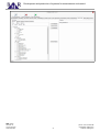
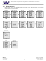
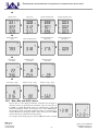
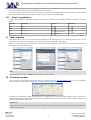
PLA 34
Power quality analyzer class S
User and service manual
version 1.6
Development and production of systems for measurement and control
Content
1. Introduction................................................................3
9.1.7. Voltage transformers.........................................14
2. Safety instructions......................................................3
9.1.8. Current transformers.........................................14
3. Packaging content.....................................................3
9.1.9. Rogowski coil measuring range........................14
9.1.10. Averaging........................................................14
4. Device description......................................................4
9.1.11. Energy.............................................................14
4.1. Front panel.........................................................4
9.2. Communication settings...................................15
4.2. Rear panel.........................................................4
9.2.1. Ethernet.............................................................15
5. Measured parameters................................................5
9.2.2. Web-server........................................................15
6. Installation..................................................................5
9.2.3. FTP server........................................................15
7. Connection.................................................................6
9.2.4. Modbus TCP.....................................................16
7.1. Grounding conductor.........................................6
9.2.5. TCP converter...................................................16
7.2. Supply voltage...................................................6
9.2.6. RS485...............................................................16
7.3. Voltage measuring inputs...................................6
9.3. NTP server, Time zone....................................17
7.4. Current measuring inputs...................................7
9.4. Email................................................................17
7.5. Current measuring inputs for PLA34RG............7
9.5. Transient..........................................................18
7.6. RS485................................................................8
9.6. Events..............................................................20
7.7. Ethernet.............................................................8
9.6.1. Voltage dip detection.........................................20
7.7.1. Connection of PLA34 into LAN...........................8
9.6.2. Voltage swell detection.....................................20
7.7.2. Connection of PLA34 to WiFi..............................9
9.6.3. RVC...................................................................21
7.7.3. Connection of PLA34 to LAN with NAT server....9
9.7. Inputs/Outputs.................................................22
7.8. USB.................................................................10
9.8. Alarms..............................................................22
7.9. Digital inputs / outputs......................................10
9.9. Display settings................................................24
8. Device settings.........................................................11
9.10. Data storage..................................................24
8.1. Menu P1...........................................................11
9.11. Memory settings.............................................26
8.2. Menu P2...........................................................11
9.12. About..............................................................26
9. Advanced setting from PMS software......................11
10. Operation...............................................................26
9.1. Main parameters..............................................11
10.1. Screens structure...........................................27
9.1.1. Network type.....................................................12
10.2. Max, Min and AVG values..............................28
9.1.2. Nominal voltage................................................13
10.3. Output signalization.......................................29
9.1.3. Nominal current.................................................14
11. Web interface.........................................................29
9.1.4. System frequency.............................................14
12. Firmware update....................................................29
9.1.5. Flicker...............................................................14
9.1.6. Ripple control....................................................14
BMR trading
Horní lán 17
779 00 Olomouc
Czech Republic
13. Technical features..................................................30
2
phone: +420 778 066 566
[email protected]
www.bmr-trading.com
Development and production of systems for measurement and control
1. Introduction
Power quality analyser PLA34 is designed for measurement of voltage network quality in LV and MV according the norm
EN 50160.
Technology of the measurement is performed according the norm “IEC 61000-4-30: Electromagnetic compatibility (EMC) –
Part 4-30: Testing and measurement techniques – Power quality measurement methods”, measurement class “Class A”.
Power quality analyser PLA44 is designed for measurement and monitoring of electrical parameters in 2, 3 and 4 conductor
networks and in TN and TT grids.
2. Safety instructions
Instrument comply the standard EN 61010-1: Safety requirements for electrical equipment for measurement, control, and
laboratory use.
• Installation of the instrument can be done by qualified and authorised person only.
• Instrument should not be installed in the environment with increased humidity and close to explosive gases.
• Use the instrument in accordance instructions written in the user manual.
• Before the disconnection of CT measuring circuits assure that terminals of CT are short circuited.
• Installation and connection changes can be done without supply voltage only.
• Do not apply supply, measuring voltage and current higher that allowed.
3. Packaging content
• Power quality analyser PLA34
• Mounting holders with screws – 2 pieces
• User manual
• Test report
BMR trading
Horní lán 17
779 00 Olomouc
Czech Republic
3
phone: +420 778 066 566
[email protected]
www.bmr-trading.com
Development and production of systems for measurement and control
4. Device description
4.1. Front panel
– key for entering menu, parameters, average, max / min values
– ESC key for canceling or return
– cursor key for moving up in menu and value increase
– cursor key for moving down in menu and value decrease
4.2. Rear panel
BMR trading
Horní lán 17
779 00 Olomouc
Czech Republic
4
phone: +420 778 066 566
[email protected]
www.bmr-trading.com
Development and production of systems for measurement and control
5. Measured parameters
Power quality analyser PLA34 is designed for measurement and monitoring of electrical parameters in 2, 3 and 4 conductor
networks and in TN and TT grids. PLA34 power quality analyser architecture is based on fast 32 bits RISC microprocessor
which provides high computing power to assure the device being fully according the norm IEC 61000-4-30 class S.
Parameter
Phase voltage
L1
L2
L3
L4
●
●
●
●
Line voltage
L1-L2 L2-L3
●
●
L3-L1
ΣL1-L3
ΣL1-L4
●
Max Min
AVG Measuring range
Displaying range Accuracy
●
●
●
10 ... 600 V
0 ... 1 MV
●
●
●
18 ... 1000 V
0 ... 1 MV
±0.2 %
±0.2 %
●
●
●
40 ... 70 Hz
40 ... 70 Hz
10 mHz
Frequency
●
Current
●
●
●
●
●
●
●
0.001 ... 6 A
0 ... 1 MA
±0.2 %
cosφ
●
●
●
●
●
●
●
0.01 L ... 0.01 C
0.01L ... 0.01C
±1 %
Power factor
●
●
●
●
●
●
●
0.01 L ... 0.01 C
0.01L ... 0.01C
±1 %
THDU L-N
●
●
●
●
●
●
●
0 ... 99.9 %
0 ... 99.9 %
±5 %
●
●
●
0 ... 99.9 %
0 ... 99.9 %
±5 %
THDU L-L
●
●
●
●
●
THDI
●
●
●
●
●
●
●
0 ... 99.9 %
0 ... 99.9 %
±5 %
Harmonics of voltage
●
●
●
●
●
●
●
0 ... 99.9 %
0 ... 99.9 %
Class 1
Group of interharmonics U
●
●
●
●
0 ... 99.9 %
0 ... 99.9 %
Class 1
Group of harmonics U
●
●
●
●
0 ... 99.9 %
0 ... 99.9 %
Class 1
Harmonics P
●
●
●
●
0 ... 99.9 %
0 ... 99.9 %
Class 1
Harmonics Q
●
●
●
●
0 ... 99.9 %
0 ... 99.9 %
Class 1
Harmonics I
●
●
●
●
0 ... 99.9 %
0 ... 99.9 %
Class 1
Group of interharmonics I
●
●
●
●
0 ... 99.9 %
0 ... 99.9 %
Class 1
Group of harmonics I
●
●
●
●
0 ... 99.9 %
0 ... 99.9 %
Class 1
Short-term flicker
●
●
●
●
Long-term flicker
●
●
●
●
Under-voltage
●
●
●
●
●
●
●
Over-voltage
●
●
●
●
●
●
●
●
●
●
●
●
●
0 ... 20.0 Pst
0.4 ... 20.0 Pst
Class A
●
●
●
0 ... 20.0 Plt
0,4 ... 20.0 Plt
Class A
●
●
●
0 ... 100 %
0 ... 100 %
±0.2 %
●
●
●
0 ... 100 %
0 ... 100 %
±0.2 %
Unbalance U
●
●
●
0 ... 100 %
0 ... 100 %
±0.15 %
Neutral point displacement
●
●
●
10 ... 600 V
0 ... 1 MV
±0.2 %
●
●
●
K-factor
●
●
●
●
Unbalance I
±0.5 %
Transients
●
●
●
●
25 μs
Events
●
●
●
●
10 ms
Ripple control signal
●
●
●
●
Active power
●
●
●
●
●
Reactive power
●
●
●
●
●
Apparent power
●
●
●
●
Distortion power
●
●
●
●
Active energy +/-
●
●
●
Reactive ind. energy +/-
●
●
Reactive cap. Energies +/-
●
●
●
●
●
●
●
●
●
●
●
●
0 ... 10.8 kW
0 ... 999 GW
±0.4 %
●
●
●
●
0 ... 10.8 kvar
0 ... 999 Gvar
±0.4 %
●
●
●
●
●
0 ... 10.8 kVA
0 ... 999 GVA
±0.4 %
●
●
●
●
●
●
0 ... 999 GWh
0 ... 999 GVh
Class 1
●
●
0 ... 999 Gvarh
0 ... 999 Gvarh
Class 2
●
●
0 ... 999 Gvarh
0 ... 999 Gvarh
Class 2
±0.5 %
* for ideal sinusoidal curve of voltage and current
Measured and displayed parameters
6. Installation
PLA34 is prepared for wall mounting in the fixed switch boards. In order to assure well ventilation, the PLA34 has to be
installed vertically. There has to be empty space at least 50 mm at the top and bottom and 20 mm at the sides.
PLA34 is fixed into switchboard wall by two clips that are placed on the device at the bottom and top.
BMR trading
Horní lán 17
779 00 Olomouc
Czech Republic
5
phone: +420 778 066 566
[email protected]
www.bmr-trading.com
Development and production of systems for measurement and control
7. Connection
Device connection at TN-C network
7.1. Grounding conductor
The grounding terminal has to be connected as a first terminal. Grounding terminal is realized by threaded pole with 3 mm
diameter and it is marked by symbol
.
7.2. Supply voltage
Supply voltage is required to operate the PLA34. The type and level of the necessary supply voltage is written on the back
label. Before applying the supply voltage, make sure that the voltage level and system frequency match the details on the
label. The connection cables for the supply voltage has to be connected using a fuse. Use a fuse (6 A type C).
7.3. Voltage measuring inputs
Instrument has four voltage measuring inputs with input impedance 4 MΩ suitable for measurement according the category
CATIII 600 V.
Each voltage measuring input have to be connected via circuit breaker or switch and fuse (10 A characteristic C) which are
placed close to the device.
Important
Supply voltage has to be from the same grid as measuring voltages
Notice
PLA34 is not designed for measuring of DC voltage!
BMR trading
Horní lán 17
779 00 Olomouc
Czech Republic
6
phone: +420 778 066 566
[email protected]
www.bmr-trading.com
Development and production of systems for measurement and control
Notice
PLA34 is not designed for usage in SELV grids!
Notice
If the voltage measuring inputs are connected over the voltage measuring transformers the power of measuring transformer
power must be at appropriate level. Voltage measuring inputs have 5 mW self consumption. Recommendation from
measuring transformer producers is to have loaded voltage measuring transformer on 70% of maximum power for the best
accuracy.
7.4. Current measuring inputs
Instrument has four current measuring inputs for indirect measurement via current measuring transformers, either ../5A
or ../1A ratio. CT ratio is freely adjustable from an instrument or via PC software.
Warning
Current inputs maximum permanent capability is 8.5 A.
Important
Before opening the current circuit be sure that measuring terminals of current transformer are connected together.
Notice
PLA34 is not designed for DC current measurement!
7.5. Current measuring inputs for PLA34RG
PLA34RG is the variant of PLA34 power quality analyser with current measuring inputs constructed by flexible Rogowski
coils. PLA34RG supports coils with 100 mV / 1 kA / 50 Hz. Rogowski coils are connected to instrument via signal wire +
(white colour), signal wire – (blue colour) and shielding. Shielding is connected to the terminal labelled S.
Inside the PLA34RG there is digital integrator for adjusting the measuring range of current input. For proper current
measurement the measuring range has to be defined by DIP switch on the rear side of the PLA34RG. The combination of
particular current measuring ranges is shown on the picture.
Note
The configuration of the current measuring range has to be set also in the instrument settings in the menu P_1 or via PMS
software. See the chapter 8.1 or 9.1.9
BMR trading
Horní lán 17
779 00 Olomouc
Czech Republic
7
phone: +420 778 066 566
[email protected]
www.bmr-trading.com
Development and production of systems for measurement and control
Important
Current measuring range changes has to be always made at opened Rogowsi coils.
7.6. RS485
The PLA34 has built-in one RS485 interface supporting Modbus RTU protocol. Connection of the RS485 bus to the device is
on the separate terminal by two wires A and B. Shielding is not required.
Note
PLA34 does not have built-in termination resistor. If the instrument is at the end of the RS485 bus it should be terminated by
120 Ω resistor.
RS485 interface is fully galvanic insulated from the supply circuits and measuring circuits.
7.7. Ethernet
Instrument is equipped by Ethernet interface 10/100Mbit/s with RJ45 connector. For connection use the cable CAT5 type.
The configuration of Ethernet is defined by the network administrator and have to be set on the PLA34 correspondingly. See
chapter 8.2.
Important
If the network configuration is not known, the Ethernet cable should not be plugged into the device.
7.7.1.
Connection of PLA34 into LAN
Make a connection to the active network item (Switch, Hub, Router) via UTP cable.
Note
PLA34 does not support the DHCP. Instrument IP address has to be configured manually at the instrument side.
BMR trading
Horní lán 17
779 00 Olomouc
Czech Republic
8
phone: +420 778 066 566
[email protected]
www.bmr-trading.com
Development and production of systems for measurement and control
7.7.2.
Connection of PLA34 to WiFi
7.7.3.
Connection of PLA34 to LAN with NAT server
If there is request for remote access (from Internet) to PLA34, which is place in the local network behind the router with
active NAT server, the following parameters configuration to be defined on the router.
For access to web server of PLA34 there has to be created port forwarding (virtual server):
• router public IP address:port 80 --> IP address of PLA34:port 80
For access to FTP server of PLA34 (needed for PMS software) there has to be created port forwarding (virtual server):
• router public IP address:port 21 --> IP of PLA34 :port 21
• router public IP address:port 50000...50005 --> IP of PLA34:port 50000...50005
Notice
Number of port of 80, 21 is possible change on router. Range of ports 50000 ... 50005 is fixed and it is not possible to
change it.
BMR trading
Horní lán 17
779 00 Olomouc
Czech Republic
9
phone: +420 778 066 566
[email protected]
www.bmr-trading.com
Development and production of systems for measurement and control
On the PLA34 device it is necessary set following parameters in:
• IP - public
• FTP: 21 (factory value)
• user name: admin (factory value)
• password: 1234 (factory value)
Notice
For communication with FTP server of PLA34 within local network is IP-public parameter set on the same as IP of the
device. For communication with FTP server of PLA34 from the internet is the IP-public parameter set on public IP obtained
from Internet provider.
7.8. USB
Device has one USB interface of type B for direct connection of PLA34 to the PC. At this moment it is used for vendor
purposes only.
7.9. Digital inputs / outputs
PLA34 is equipped with two optically-isolated transistor outputs inputs. The outputs working mode is fully adjustable as an
alarm output, remotely controlled output or pulse output.
Input / output connection
BMR trading
Horní lán 17
779 00 Olomouc
Czech Republic
10
phone: +420 778 066 566
[email protected]
www.bmr-trading.com
Development and production of systems for measurement and control
8. Device settings
Before usage of the PLA34 instrument it is necessary set several parameters essential for correct operation of the instrument
in the different type of installations.
PLA34 device can be configured from panel screen for most of the essential parameters. Configuration menu is divided to the
two sub-menus for device fundamental settings and menu for communication interfaces settings. Enter the configuration
menu by pressing the button SET for at least 5 seconds.
For moving in the menu use cursor keys ▲ and ▼. Key ▲ is normally used for circle moving in the menu. Parameters
setting is activated by pressing the key SET. Changing the parameter setting is done by cursor keys ▲ and ▼, confirmation
of newly set parameter value by key SET. Key ESC cancels setting or move back to higher menu or back to normal
operation.
Most of the device parameter and functions can be enabled and configured only by PC and software PMS.
8.1. Menu P1
Menu of fundamental settings of instrument such as transformers ratio, display behaviour and internal clock.
Parameter
Description
Factory setting
bcL
Device display backlight
Utr
Voltage measuring transformer ratio
Itr
Current measuring transformer ratio
Y, M, d
Calendar settings (Y – year, M – month, d – day)
H, M
Internal clock setting (H – hours, M - minutes)
PAS
Instrument password settings
rES
Device configuration reset to the factory settings
----
Setting range
0001 ... 9999
Important
For the instrument variant PLA34RGP set the Itr parameter on the same measuring range as DIP switch on rear side of the
instrument. The setting as Itr parameter can be done performed via Power Monitoring Software.
8.2. Menu P2
Settings related to the communication interfaces of instrument.
Parameter
Description
Factory settings
Settings range
IP
PLA34 IP address in the local network
192.168.001.201
MAS
Mask of the Ethernet network
255.255.255.0
GAt
IP address of PC or router used as a gateway to parent network
192.168.001.001
PIP
Public IP address of router
192.168.001.001
Id
Unique identification number in RS485 network
0
0 ... 255
bd
Communication speed of RS485 interface is adjustable in speed
9.6 kBd
9.6 kBd ... 115 kBd
PAr
RS485 interface parity
odd
odd / even
St
RS485 interface stop-bit
1
1/2
9. Advanced setting from PMS software
PLA34 instrument itself offers fundamental setting since the display capabilities are limited for an advanced setting.
9.1. Main parameters
Setting “Main parameters” gathers all settings related to measuring circuits connection type, measuring transformers and type
of parameters calculation.
BMR trading
Horní lán 17
779 00 Olomouc
Czech Republic
11
phone: +420 778 066 566
[email protected]
www.bmr-trading.com
Development and production of systems for measurement and control
Parameter
9.1.1.
Description
Factory settings
Settings range
Type of connection
Defines the type of network and measuring circuit connection
3UN_4I
Chapter 9.1.1
Nominal voltage
Network nominal phase voltage
230 V
1V ... 750 kV
Nominal current
Network nominal phase current
5A
1A ... 750 kA
System frequency
Defines the nominal system frequency
50 Hz
45 ... 75 Hz
Flicker
Parameter of the nominal voltage and frequency for flicker calculation
230V - 50Hz
120/230V, 50/60Hz
Voltage transformer ratio
Enable the usage of measuring voltage transformer
No
No / Yes
Primary voltage
Primary voltage of measuring voltage transformer in case of its usage
230V
1 ... 750 kV
Secondary voltage
Secondary voltage of measuring voltage transformer in case of its usage
230V
1 ... 750 kV
Current transformer ratio
Enable the usage of measuring current transformer
No
No / Yes
Primary current
Primary current of measuring current transformer in case of its usage
1A
1 ... 750 kA
Secondary current
Secondary current of measuring current transformer in case of its usage
1A
1/5A
Type of averaging
Type of averaging method
Static
Static / Sliding
Averaging period
Time for averaging period setting
5s
1 ... 3600s
Storage interval
Interval of energy meters profile
15 min
15, 30, 45, 60 min
Ripple -control
Adjustable by PMS
50 Hz
50 Hz ... 3 kHz
Network type
PLA34 is designed for various connections according to the grid type or measurement needs. Network settings defines the
types network system in which the PLA34 is connected. The main connection diagram of PLA34 is shown in chapter 7. In the
following table are shown all possible connection variants that can be defined in the device menu.
BMR trading
Horní lán 17
779 00 Olomouc
Czech Republic
12
phone: +420 778 066 566
[email protected]
www.bmr-trading.com
Development and production of systems for measurement and control
Connection for asymmetric loads in TN-C-S grids
Connection for asymmetric loads in TN-C or TN-C-S
Connection for single-phase loads
Connection for symmetric loads with two CT only
Connection for MV grid (Aron connection)
9.1.2.
Nominal voltage
Nominal voltage setting is fundamental setting used for capturing thresholds of voltage events and transients. Appropriate
BMR trading
Horní lán 17
779 00 Olomouc
Czech Republic
13
phone: +420 778 066 566
[email protected]
www.bmr-trading.com
Development and production of systems for measurement and control
value of phase nominal voltage has to be set.
9.1.3.
Nominal current
Nominal current setting is fundamental value setting used for threshold calculation for current events.
9.1.4.
System frequency
PLA34 is designed for measurement in the 50 Hz and 60 Hz networks. Select the right system frequency for correct sampling
of measured voltages and currents.
9.1.5.
Flicker
PLA34 calculates flicker according to the norm EN 61000-4-15. It provides values for short-term flicker (10 minutes), longterm flicker (2 hours). For correct calculation of both flickers it is necessary set correct nominal values used in the country
standards. Available settings are:
• 230 V – 50 Hz
• 230 V – 60 Hz
• 120 V – 50 Hz
• 120 V – 60 Hz
9.1.6.
Ripple control
9.1.7.
Voltage transformers
If the voltage measuring transformers are used the settings of primary and secondary voltage has to be configured. Both
voltage levels (primary and secondary) are set in volts.
9.1.8.
Current transformers
PLA34 instrument has 4 current inputs for indirect measurement via current transformers with secondary current 5A or 1A. In
case of measuring current transformer usage the primary and secondary current value of CT has to be set.
9.1.9.
Rogowski coil measuring range
PLA34RG is an instrument with current measuring inputs designed for connection of Rogowski coils. Instead of current
transformer ratio the current measuring range is set. The sensitivity of Rogowski coil allows the wide range setting from 10 A
till 10 kA.
Note
For correct current measurement check that the DIP switch of current measuring range of Rogowski coil is set on the same
value as setting in PLA34RG configuration. For more information see the chapter 7.5
9.1.10.
Averaging
This setting defines type of averaging and period of average values calculation. Average values are available on the display of
an instrument and in Power Monitoring Software.
There are two types of averaging method:
• Static window method cumulates measured values over the defined period. After the period ends the average values are
calculated and shown. Cumulated values are erased and new period is measured again.
• Sliding window method continually cumulates measured values over the defined period and over this period shows
calculated average values. While the time is moving the oldest values are erased and new values added.
9.1.11.
Energy
Provides setting of recording interval for historical values of energy counters available in PLA34.
BMR trading
Horní lán 17
779 00 Olomouc
Czech Republic
14
phone: +420 778 066 566
[email protected]
www.bmr-trading.com
Development and production of systems for measurement and control
9.2. Communication settings
Instrument is equipped by one Ethernet interface 10/100Mbit/s and RS485. In the PMS software, settings of all available
communication interfaces are grouped in cart called “Communication”.
9.2.1.
Ethernet
Defines the configuration of Ethernet interface of instrument for visibility and accessibility on LAN and Internet.
Parameter
Description
Factory setting
IP address
PLA44 IP address in the local network
192.168.001.201
IP Mask
Mask of the Ethernet network
255.255.255.0
Gateway
IP address of PC or router used as a gateway to parent network
192.168.001.001
Public IP address
Public IP address of router
192.168.001.001
MAC
Web-server settings advance menu
Setting range
Important
Public IP address is necessary to set for these cases when instrument is accessed from different network, for example
Internet, while it is located in the Ethernet behind the NAT server.
9.2.2.
Web-server
Instrument has build in web-server for remote on-line monitoring via Internet or local network. Following table describes
settings related to web server configuration of PLA34.
Parameter
Description
Factory setting
WEB server
Activates the internal web server of PLA34
Yes
User name
Web-server user name
admin
Password
Web-server password
1234
Web port
Port of web server
80
Setting range
Yes / No
1 ... 65535
Notice
Web server is optimized for portable instruments such as mobile phones and tablets.
9.2.3.
FTP server
FTP server is a fundamental communication protocol for reading the measured data, recorded data and configuration of the
BMR trading
Horní lán 17
779 00 Olomouc
Czech Republic
15
phone: +420 778 066 566
[email protected]
www.bmr-trading.com
Development and production of systems for measurement and control
instrument. Enabled FTP is server is an essential setting needed for correct work of PLA34 with Power Monitoring Software.
Parameter
Description
Factory setting
FTP server
Activates the internal FTP server of PLA34
Yes
User name
FTP server user name
admin
Password
FTP server password
1234
FTP port
Port of FTP server
21
9.2.4.
Setting range
Yes / No
1 ... 65535
Modbus TCP
Communication protocol Modbus TCP is used for communication with PLA34 over the Ethernet interface.
Parameter
Description
Factory setting
Setting range
Modbus TCP
Activates the Modbus TCP communication protocol of PLA34
Yes
Yes / No
Modbus port
Port of Mobus TCP communication
502
1 ... 65535
Note
On the request the table of Modbus registers can be provided. Please, contact us on [email protected].
9.2.5.
TCP converter
PLA34 is equipped by function of Modbus TCP converter so it can provide access to instruments connected on RS485 bus of
PLA34.
Parameter
Description
Factory setting
Setting range
TCP converter
Activates the Modbus TCP converter of PLA34
Yes
Yes / No
Converter timeout
Converter timeout
500 ms
100 ... 5000 ms
Modbus TCP converter function has allowed Modbus user functions so it is suitable for transmission of long data packets
such as recorded data from flash memory of PLA33CMB instruments.
9.2.6.
RS485
Serial port RS485 configuration is essential for the usage of PLA34 as a TCP/IP converter.
Parameter
Description
Factory setting
Setting range
ID
Unique identification number in RS485 network
0
0 ... 255
Transfer rate
Communication speed of RS485 interface is adjustable in speed
9.6 kBd
9.6 kBd ... 115 kBd
Parity
RS485 interface parity
odd
odd / even
Stop bit
RS485 interface stop-bit
1
1/2
BMR trading
Horní lán 17
779 00 Olomouc
Czech Republic
16
phone: +420 778 066 566
[email protected]
www.bmr-trading.com
Development and production of systems for measurement and control
9.3. NTP server, Time zone
PLA34 corrects internal clock according to NTP servers while it is connected to Internet. NTP time synchronization has
always priority above the manual clock settings. Clock synchronization by NTP is fully automatic and there is no need to set
anything.
The selection of closest NTP server is adjustable in software PMS. For the finding the closest NTP server refer to the
following link http://support.ntp.org/bin/view/Servers/StratumOneTimeServers.
9.4. Email
PLA34 can notice several events and alarms by sending an e-mail up to 4 different e-mail addresses. The email notification
setting is available only from Power Monitoring Software.
For correct setting obtain the SMTP server address from your provider. If the SMTP server requires authentication enter the
BMR trading
Horní lán 17
779 00 Olomouc
Czech Republic
17
phone: +420 778 066 566
[email protected]
www.bmr-trading.com
Development and production of systems for measurement and control
user name and password.
Select the requested e-mail notification and sending interval. Sending interval defines how often the emails are sent in order
to prevent
Sending interval defines how often the email is sent. Factory setting is 1 hour which means that all events and alarms that
appears during that hour are sent in one email. This interval prevents the instrument to send too many e-mails.
For most recent 5 events and transients the graphs are sent in the e-mail too. Other events and transients are shown as a
recording in table.
9.5. Transient
Voltage transients are short commutation, impulse or oscillatory events in electrical grid. Their source can be inductive load
switching, power factor correction instruments, atmospheric events, protection instruments action or malfunction of switching
elements in the grid.
PLA34 analyser detects two types of transients. Absolute transients and differential transients.
• Absolute transients are detected according to override of defined voltage level. The trigger for detection of the absolute
transients is defined by absolute threshold (percentage of Udin).
• Differential transients are detected according to the difference between two consecutive voltage measurements. The
difference between measurement is defined by differential threshold (percentage of Udin).
Common settings for absolute and differential transients is for the parameters used for tuning the transients detection and
transients recording.
If the transient is detected and being recorded the instrument increase the absolute and differential thresholds to prevent of
misled transient detection. It prevents instrument against wrong recordings. This is defined by two user adjustable parameters.
Increase value and increase time.
BMR trading
Horní lán 17
779 00 Olomouc
Czech Republic
18
phone: +420 778 066 566
[email protected]
www.bmr-trading.com
Development and production of systems for measurement and control
• Increase value is the value that is used for increasing the absolute and differential threshold while transient is detected. Set
value increase the threshold level for the defined time.
• Increase time is a time delay for which the increased value of threshold is valid. After the increase time expires the value
of threshold is returned back the user set value.
If another transient appears while the increase time is still not expired the threshold is increased once again. After the
increased time expires the threshold is recovered to the previous level and after another period of increase time it is threshold
recovered to the user defined level of absolute and differential thresholds.
Parameter
Description
Factory setting
Setting range
Absolute transient
Absolute transient activation
No
YES / NO
Absolute threshold
Threshold absolute transient setting
110%
100 ... 500%
Difference transient
Difference transient activation
No
YES / NO
Difference threshold
Threshold difference transient setting
20%
1 ... 100%
Increase time
Time delay before next transient recording after transient start
5s
1 ... 20 s
Increase value
Increment value for transient insensitivity after recording start
10V
1 ... 750000 V
Post samples
Number of recorded samples after the transient start
768
0 ... 8000
Pre samples
Number of recorded samples before the transient start
768
0 ... 8000
Memory space for capturing of the particular transients is fixed on the maximum of 8000 samples. Definition of number Pre
and Post samples is limited by this maximum samples memory space.
BMR trading
Horní lán 17
779 00 Olomouc
Czech Republic
19
phone: +420 778 066 566
[email protected]
www.bmr-trading.com
Development and production of systems for measurement and control
9.6. Events
Events captured by PLA34 are fully adjustable by the parameters described in the table beneath.
Parameter
Description
Reference
Factory setting
Setting range
Reference voltage level type
Udin
Udin / Sliding
Threshold
110%
100 ... 500%
Hysteresis
5%
1 ... 20%
Threshold
90%
1 ... 100%
Hysteresis
5%
1 ... 20%
Threshold
5%
1 ... 100%
Hysteresis
2%
1 ... 20%
Threshold
110%
100 ... 500%
Hysteresis
5%
1 ... 20%
Pre Samples
Number of recorded half periods Urms1/2 (10ms = 1) before event
10
0 ... 4000
Post Samples
Number of recorded half periods Urms1/2 (10ms = 1) after event
150
0 ... 4000
Over-voltage
►
Under-voltage
►
Interruption
►
Over-current
►
Memory for capturing the samples of RMS curve is fixed on the maximum of 4000 samples. Definition of number Pre and
Post samples is limited by this maximum samples memory space.
9.6.1.
Voltage dip detection
The dip threshold is a percentage of either Udin or the sliding voltage reference. The user shall declare the reference voltage
in use.
• On single-phase systems a voltage dip begins when the Urms voltage falls below the dip threshold, and ends when the
Urms voltage is equal to or above the dip threshold plus the hysteresis voltage.
• On poly-phase systems a dip begins when the Urms voltage of one or more channels is below the dip threshold and ends
when the Urms voltage on all measured channels is equal to or above the dip threshold plus the hysteresis voltage.
The dip threshold and the hysteresis voltage are both set by the user according to the use.
9.6.2.
Voltage swell detection
The swell threshold is a percentage of either Udin or the sliding reference voltage. The user shall declare the reference
voltage in use.
• On single-phase systems a swell begins when the Urms voltage rises above the swell threshold, and ends when the Urms
BMR trading
Horní lán 17
779 00 Olomouc
Czech Republic
20
phone: +420 778 066 566
[email protected]
www.bmr-trading.com
Development and production of systems for measurement and control
voltage is equal to or below the swell threshold minus the hysteresis voltage.
• On poly-phase systems a swell begins when the Urms voltage of one or more channels is above the swell threshold and
ends when the Urms voltage on all measured channels is equal to or below the swell threshold minus the hysteresis
voltage.
The swell threshold and the hysteresis voltage are both set by the user according to the use.
9.6.3.
RVC
A Rapid Voltage Change (RVC) is an event characterized by a quick transition from one steady-state voltage to another.
Typically, RVC events are counted for a period of one hour, or for each day. Mains signalling voltage, called “ripple control
signal” in certain applications, is a burst of signals, often applied at a non-harmonic frequency, that remotely control
industrial equipment, revenue meters, and other devices.
If the change in voltage is sufficient to cross the dip threshold or the swell threshold, then the event shall not be recorded as
an RVC event. It is a dip or a swell.
The RVC threshold (or thresholds) and the RVC hysteresis are both set by the user according to the use. The RVC threshold is
a percentage of Udin. The RVC hysteresis is a smaller percentage of Udin.
NOTE
Although RVC and Flicker both may cause changes in illumination levels that irritate people, the two are different in
concept. RVC is a discrete event, while flicker is a quasi-stationary condition.
Parameter
Description
Factory setting
Setting range
RVC threshold
The RVC threshold is a percentage of Udin
3.3%
1 ... 100%
RVC hysteresis
The RVC hysteresis is a smaller percentage of Udin
1%
1 ... 20%
According to the norm the ideal settings is RVC threshold on 3.5% of Udin and hysteresis on 1% of Udin.
BMR trading
Horní lán 17
779 00 Olomouc
Czech Republic
21
phone: +420 778 066 566
[email protected]
www.bmr-trading.com
Development and production of systems for measurement and control
9.7. Inputs/Outputs
Analyser PLA34 has two user configurable inputs/outputs. Connection of the inputs and outputs is displayed in the chapter
7.9.
Parameter
Description
Factory setting
Channel type
Defines the usage of the input and output interface
Source of pulses
Setting available only for Pulse_out channel type
Pulse weight
Setting available only for Pulse_out and Pulse_in channel type
Unit
Setting available only for Pulse_in channel type. Defines the unit of pulses
Digi out
Available only for Digi_out channel type. Defines fundamental state of
output.
Digi_in
Setting range
Digi_in / Digi_out /
Pulse_in / Pulse_out /
Alarm
0
Off
On / Off
9.8. Alarms
Instrument is equipped by two input / output terminals which can be programmed to the four different states. Terminal one or
two can be set to work as an alarm output.
Each output, while it is set to behave as an alarm, consists from three comparators. Comparators are sorted into logical
function according to following diagram.
BMR trading
Horní lán 17
779 00 Olomouc
Czech Republic
22
phone: +420 778 066 566
[email protected]
www.bmr-trading.com
Development and production of systems for measurement and control
Comparators C1, C2 and C3 belong to the output K1 and comparators C4, C5 and C6 to output K2. From the picture is
visible that there are logical function between first two comparators of the group and between their result and last comparator
of the group. There are two logical operators available, logical conjunction – AND and logical disjunction – OR.
Important
For correct work of an alarm it is necessary set the instrument outputs to behave as an alarm outputs. See the chapter 9.7.
Proper connection of outputs is described in chapter 7.9.
BMR trading
Horní lán 17
779 00 Olomouc
Czech Republic
23
phone: +420 778 066 566
[email protected]
www.bmr-trading.com
Development and production of systems for measurement and control
9.9. Display settings
Parameter
Description
Factory setting
Setting range
Refresh time [cycle]
Refresh time of the displayed values.
5
1... 50
Backlight [%]
Backlight intensity of instrument LCD display.
50
0 ... 100
Without any action on keyboard of an instrument the device backlight will turn off in 120s.
It is possible to set permanent ON of the display backlight. This case the backlight will light on 50%. Permanent OFF keeps
the backlight with 5%.
9.10. Data storage
Measured parameters can be recorded in the internal flash memory. For this purposes cart Data storage offers the list of all
parameters that can be stored. PLA34 allows to define 5 different time intervals with adjustable time and recorded
parameters.
List of recorded parameters of all intervals can be saved as a template for further usage. There is also predefined template
according the power quality norm EN50160.
BMR trading
Horní lán 17
779 00 Olomouc
Czech Republic
24
phone: +420 778 066 566
[email protected]
www.bmr-trading.com
Development and production of systems for measurement and control
BMR trading
Horní lán 17
779 00 Olomouc
Czech Republic
25
phone: +420 778 066 566
[email protected]
www.bmr-trading.com
Development and production of systems for measurement and control
9.11. Memory settings
Memory of the PLA34 is possible be managed to obtain more space for preferred recordings. Simple move of particular
memory are borders modify the size of available space.
9.12. About
Information about the vendor and device firmware version.
10. Operation
PLA34 allows simple operation of basic screens with most interesting parameters.
For moving in the menu use cursor keys ▲ and ▼. Key ▼ is normally used for circle moving in the one level of screens.
Key ▲ moves to another level of screens. Pressing the button SET shows maximums, minimums and average values of
displayed parameters. ESC key returns back to first screen.
Full list of measured parameters, events and transients is available via the web server or PC and monitoring software PMS.
BMR trading
Horní lán 17
779 00 Olomouc
Czech Republic
26
phone: +420 778 066 566
[email protected]
www.bmr-trading.com
Development and production of systems for measurement and control
10.1. Screens structure
Meaning of each screen is easily identified by usage of standard ISO symbols and value parameters. Every displayed
parameter value is shown with its variable.
Phase voltage
Phase to phase voltage
▼
3rd voltage harmonics
Voltage THD
▼
▼
19th voltage harmonics
..
▼..
▲
Phase current
Current in neutral
▼
3rd current harmonics
Current THD
▼
▼
19th current harmonics
..
▼..
▲
System frequency
▲
Cos φ
Power factor
▼
▲
BMR trading
Horní lán 17
779 00 Olomouc
Czech Republic
27
phone: +420 778 066 566
[email protected]
www.bmr-trading.com
Development and production of systems for measurement and control
▲
Apparent power
Active power
▼
Reactive inductive power
▼
Reactive capacitive power
▼
▲
Apparent three-phase
power
Reactive inductive threephase power
Active three-phase power
▼
▼
Reactive capacitive threephase power
▼
▲
Active energy –
consumption
Reactive L energy –
consumption
▼
Reactive C energy consumption
▼
▲
Active energy – supply
Reactive L energy – supply
▼
Reactive C energy - supply
▼
10.2. Max, Min and AVG values
PLA34 shows on the display maximums, minimums and averages of
measured values. For presenting the maximum value one short press of
key SET is needed. Maximum values are symbolized by symbol ▲
before the displayed number. Second short press of key SET displays
the minimum values if available. Minimum values are symbolized by
symbol ▼ before the displayed number. Third short press of key SET
will turn back to the instantaneous measurement.
For average values displaying press the key SET three-times. Average
BMR trading
Horní lán 17
779 00 Olomouc
Czech Republic
28
phone: +420 778 066 566
[email protected]
www.bmr-trading.com
Development and production of systems for measurement and control
value is introduced by displayed symbols ▲ and ▼ at the same time.
Since the average value of powers is four-quadrant the average value of consumption is introduced only by symbols ▲ and
▼. For distribution the value is introduced by negative sign between symbols ▲ and ▼.
10.3. Output signalization
Outputs can be operated in four states. Signalization on the LCD is common for all of them and differs according to following
table.
Parameter
Description
Activated
In
input
Out
output
PuL
pulse output
at pulse presence
AL
alarm output
flashing
Deactivated
11. Web interface
PLA34 has build in web server to show measured parameters in the internet browsers. For enabling the web server see the
chapter 9.2.2. Web server is designed for web browsers compatible with HTML5 specification.
Web server of an instrument is available after setting the instrument IP address to the web browser. Access to the web page is
protected by user name and password.
Note
Factory setting of user name is admin. Password factory setting is 1234.
12. Firmware update
Device firmware can be update when the new firmware is released. Visit the www.bmr-trading.com for to verify availability
of new firmware. Firmware file is prepared as an exe file that is directly run on Windows PC.
For the successful firmware update connect the PLA34 via Ethernet to PC where the Update software will run. Enter the IP
address of the PLA34 and user name and password. Pressing button Connect will verify accessibility of PLA34 and prepare
connection for firmware update start.
Important
While firmware is being updated, device should be connected to stable power supply and Ethernet connection should not be
removed or interrupted.
BMR trading
Horní lán 17
779 00 Olomouc
Czech Republic
29
phone: +420 778 066 566
[email protected]
www.bmr-trading.com
Development and production of systems for measurement and control
13. Technical features
Parameter
Value
Supply voltage
85 ... 265 VAC/DC
Power consumption
< 4 VA
Voltage measuring range L - N
10 ... 600 VAC
Voltage measuring range L - L
18 ... 1000 VAC
Current measuring range
0.001 ... 6 (8.5) A
Frequency measuring range
40 ... 70 Hz
Clock accuracy
< 1 s per day
Number of output / input
2
Output type
NPN transistor free potential optical insulated
Maximum voltage for output usage
24 VDC
Maximum output load capability
100 mA
Input type
optical insulated free potential
Maximum input voltage
24 VDC
Maximum input consumption
10 mA
Voltage transformer ratio
1 ... 750 000
Current transformer ratio
1 ... 750 000
Supply voltage power cuts memory
15 events
Sampling rate
40 kHz
Events trigger
10 ms
Data memory for measured parameters
1 GB
Display type and size
LCD
Communication port
RS485 (optional) / Modbus RTU / 9.6, 19.2, 38.4 ... 115 kBd
Ethernet
RJ45 / 10/100 Mbit
USB
Type B
Over-voltage class
600V CATIII
Pollution degree
2
Temperature limit
-25°C ... +60°C
Front panel dimensions
96 x 96 mm
Panel cutout dimensions
92 x 92 mm
Site depth
75 mm
Weight
525 g
Protection degree
IP20 rear cover / IP54 front panel
Related standards
EN 61000-4-30 class S, EN 61000-4-7, EN 61000-4-15, EN 61557-12
BMR trading
Horní lán 17
779 00 Olomouc
Czech Republic
30
phone: +420 778 066 566
[email protected]
www.bmr-trading.com