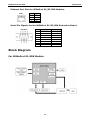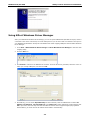
1
MiiNePort E1/E2-SDK User’s Manual First Edition, February 2015 www.moxa.com/product © 2015 Moxa Inc. All rights reserved. Reproduction without permission is prohibited. MiiNePort E1/E2-SDK User’s Manual The software described in this manual is furnished under a license agreement and may be used only in accordance with the terms of that agreement. Copyright Notice Copyright ©2015 Moxa Inc. All rights reserved. Reproduction without permission is prohibited. Trademarks The MOXA logo is a registered trademark of Moxa Inc. All other trademarks or registered marks in this manual belong to their respective manufacturers. Disclaimer Information in this document is subject to change without notice and does not represent a commitment on the part of Moxa. Moxa provides this document as is, without warranty of any kind, either expressed or implied, including, but not limited to, its particular purpose. Moxa reserves the right to make improvements and/or changes to this manual, or to the products and/or the programs described in this manual, at any time. Information provided in this manual is intended to be accurate and reliable. However, Moxa assumes no responsibility for its use, or for any infringements on the rights of third parties that may result from its use. This product might include unintentional technical or typographical errors. Changes are periodically made to the information herein to correct such errors, and these changes are incorporated into new editions of the publication. Technical Support Contact Information www.moxa.com/support Moxa Americas Moxa China (Shanghai office) Toll-free: 1-888-669-2872 Toll-free: 800-820-5036 Tel: +1-714-528-6777 Tel: +86-21-5258-9955 Fax: +1-714-528-6778 Fax: +86-10-6872-3958 Moxa Europe Moxa Asia-Pacific Tel: +49-89-3 70 03 99-0 Tel: +886-2-8919-1230 Fax: +49-89-3 70 03 99-99 Fax: +886-2-8919-1231 Table of Contents 1. Introduction ...................................................................................................................................... 1-1 Overview ........................................................................................................................................... 1-2 Package Checklist ............................................................................................................................... 1-2 Product Features ................................................................................................................................ 1-2 Product Specifications ......................................................................................................................... 1-3 Panel Layout ...................................................................................................................................... 1-4 MiiNePort E1-SDK Evaluation Board Panel Layout ............................................................................ 1-4 MiiNePort E2-SDK Evaluation Board Panel Layout ............................................................................ 1-5 Block Diagram .................................................................................................................................... 1-6 For MiiNePort E1-SDK Module ....................................................................................................... 1-6 For MiiNePort E2-SDK Module ....................................................................................................... 1-7 LED Indicators .................................................................................................................................... 1-7 2. Getting Started.................................................................................................................................. 2-1 Wiring Precautions .............................................................................................................................. 2-2 Selecting the Serial Interface ............................................................................................................... 2-2 Connecting Power ............................................................................................................................... 2-3 Connecting MiiNePort USB to PC ........................................................................................................... 2-3 Connecting to the Network................................................................................................................... 2-5 Connecting to a Serial Device ............................................................................................................... 2-5 Digital I/O Channel Settings ................................................................................................................. 2-5 Schematic Design Guide ...................................................................................................................... 2-6 3. Choosing the Proper Operation Mode ................................................................................................ 3-1 Overview ........................................................................................................................................... 3-2 RealCOM Mode ................................................................................................................................... 3-2 Ethernet Modem Mode......................................................................................................................... 3-3 4. Utility Console and Driver Installation .............................................................................................. 4-1 NPort Search Utility............................................................................................................................. 4-2 Installing NPort Search Utility ....................................................................................................... 4-2 NPort Search Utility Configuration ................................................................................................. 4-3 NPort Windows Driver Manager ............................................................................................................ 4-4 Installing NPort Windows Driver Manager ....................................................................................... 4-4 Using NPort Windows Driver Manager ............................................................................................ 4-6 Linux Real TTY Drivers ........................................................................................................................ 4-8 Installing Linux Real TTY Driver Files ..................................................................................................... 4-8 Mapping TTY Ports ....................................................................................................................... 4-8 Removing Mapped TTY Ports ......................................................................................................... 4-9 Removing Linux Driver Files.......................................................................................................... 4-9 UNIX Fixed TTY Drivers ....................................................................................................................... 4-9 Installing the UNIX Driver............................................................................................................. 4-9 Configuring the UNIX Driver ....................................................................................................... 4-10 5. MiiNePort IDE Development Tool ...................................................................................................... 5-1 Installing MiiNePort IDE ....................................................................................................................... 5-2 Starting MiiNePort IDE......................................................................................................................... 5-5 Create MiiNePort-SDK Project ............................................................................................................... 5-6 RealCOM Mode ............................................................................................................................ 5-7 Ethernet Modem Mode ................................................................................................................. 5-9 Sample Application ...................................................................................................................... 5-9 Data Packing ............................................................................................................................ 5-10 Serial Command Mode ............................................................................................................... 5-12 Web Console............................................................................................................................. 5-16 CLI .......................................................................................................................................... 5-16 SNMP agent .............................................................................................................................. 5-17 TFTP Server .............................................................................................................................. 5-18 NTP Client ................................................................................................................................ 5-18 CPU Monitor.............................................................................................................................. 5-19 Wizards ........................................................................................................................................... 5-19 Modify project dependency ......................................................................................................... 5-20 CLI Wizard ............................................................................................................................... 5-20 Configuration Wizard ................................................................................................................. 5-23 SCM Wizard .............................................................................................................................. 5-25 SNMP Wizard ............................................................................................................................ 5-27 User App Wizard ....................................................................................................................... 5-29 Build project ............................................................................................................................. 5-31 Upload debug version firmware to MiiNePort ................................................................................. 5-31 Debug current active project....................................................................................................... 5-31 Upload your customized firmware to MiiNePort .............................................................................. 5-32 6. NetEZ Technologies ........................................................................................................................... 6-1 SCM (Serial Command Mode) ............................................................................................................... 6-2 EXTrigger (External Trigger) ................................................................................................................ 6-3 EZPower ............................................................................................................................................ 6-4 A. Introduction to SCM (Serial Command Mode) Command Set ............................................................. A-1 Command/Reply Format ...................................................................................................................... A-2 Single Line Command Format ....................................................................................................... A-2 Single Line Reply Format .............................................................................................................. A-2 Head and Tail Format................................................................................................................... A-2 Operation Codes ......................................................................................................................... A-2 Status Codes .............................................................................................................................. A-2 Restriction .................................................................................................................................. A-2 Command Code .................................................................................................................................. A-3 Command Code for Getting the Configuration ................................................................................. A-3 Command Codes for Retrieving Running Configuration ..................................................................... A-5 Command Codes for Viewing the Status ......................................................................................... A-7 Control Command Codes .............................................................................................................. A-7 B. Well Known Port Numbers ................................................................................................................ B-1 C. SNMP Agent with MIB II and RS-232 Like Groups ............................................................................. C-1 D. Supported File Systems ..................................................................................................................... D-1 1 1. Introduction The MiiNePort E1/E2-SDK Series embedded device servers are compact drop-in modules that can be integrated with your serial devices to enable connectivity to an Ethernet network. All MiiNePort E1/E2-SDK Series modules come equipped with built-in TCP/IP protocols and other easy-to-use network enabling tools for fast integration, allowing you to provide network access to any electronic device with a serial port. The following topics are covered in this chapter: Overview Package Checklist Product Features Product Specifications MiiNePort E1-SDK Evaluation Board Panel Layout MiiNePort E2-SDK Evaluation Board Panel Layout Block Diagram For MiiNePort E1-SDK Module For MiiNePort E2-SDK Module LED Indicators MiiNePort E1/E2-SDK Introduction Overview The Moxa MiiNePort E1/E2-SDK Series products are serial-to-Ethernet embedded modules. Moxa provides development and debug kit which includes JTAG, an Eclipse-based integrated software development tool, and a source level debugger. The following table lists the model names of all MiiNePort E1/E2-SDK series modules, along with the model names of the corresponding starter kits. Package Checklist Available Models: • MiiNePort E1-SDK: Software Development Kit for the MiiNePort E1 Series, MiiNePort E1 module included • MiiNePort E2-SDK: Software Development Kit for the MiiNePort E2 Series, MiiNePort E2 module included Package Checklist: • MiiNePort E2-SDK module or MiiNePort E1-SDK module • MiiNePort E2-SDK evaluation board or MiiNePort E1-SDK evaluation board • Universal power adaptor • 2 power cords • Null modem cable • Cross-over Ethernet cable • Documentation and Software CD • Quick Installation Guide (printed) • Warranty Card NOTE: Please notify your sales representative if any of the above items is missing or damaged. Product Features All MiiNePort E1/E2-SDK modules have the following general features: • Eclipse-based integrated software development tool • Source-level debugger • Easy to build proprietary SNMP/CLI console • Various serial-to-Ethernet sample code • Mass production tool for easy firmware upload • Supports RealCOM mode operation functions 1-2 MiiNePort E1/E2-SDK Introduction Product Specifications Supported Hardware MiiNePort E1/E2 MiiNePort E1/E2-H MiiNePort E1/E2-T MiiNePort E1/E2-H-T Software OS: eCos Software Development Tool: MiiNePort-IDE Windows RealCOM Drivers: Windows 98/ME/NT/2000, Windows XP/2003/Vista/2008/7/8/8.1 x86/x64, Embedded CE 5.0/6.0, XP Embedded Fixed TTY Drivers: SCO Unix, SCO OpenServer, UnixWare 7, SVR 4.2, QNX 4.25, QNX 6, Solaris 10, FreeBSD, AIX 5.x Linux Real TTY Drivers: Linux kernel 2.4.x, 2.6.x, 3.0.x Operation Modes: RealCOM, Ethernet Modem Wizard: Project/SNMP/CLI(Telnet)/SCM/User Configuration Serial/Ethernet Test Tool: PComm Lite (Serial/TCP Server/TCP Client) Search/Upload Firmware Utility: NPort Search Utility Serial to Ethernet Sample Source Code (Integrated in MiiNePort-IDE): 1. TCP Server Echo 2. TCP Server to Serial (Single connection) 3. TCP Server to Serial (Multi-connection) 4. TCP Client Echo 5. TCP Client to Serial (Startup) 6. TCP Client to Serial (Any character) 7. TCP Client to Serial (Designed destination TCP/IP port from serial) 8. UDP echo 9. UDP to serial Documents API Function Helper, User's Manual, Getting Started, Schematic Design Guide, Quick Installation Guide 1-3 MiiNePort E1/E2-SDK Introduction Panel Layout MiiNePort E1-SDK Evaluation Board Panel Layout Number Description 1 MiiNePort E1 Module Location 2 USB Type B Connector (Debug) 3 Configurable Pin Jumper 4 Digital Input Switch 5 Digital Output LED 6 Digital IO Terminal Block 7 Serial Port Status LED 8 DB9 Male Connector 9 Serial Interface Jumper 10 Power LED 11 Power Jack 12 Restart Button 13 Circuit Pad ATTENTION Users must set jumpers JP15, JP16, and JP17 to correspond with the functions of pins 6, 7, and 8, respectively, to ensure that the evaluation board works properly. ATTENTION When you are in RS-485 mode, 485EN must be configured by either JP15 or JP16, and the 6-pin jumper must be moved from JP19 to JP20. 1-4 MiiNePort E1/E2-SDK Introduction ATTENTION Before you manipulate the jumpers, be sure to disconnect the power first. MiiNePort E2-SDK Evaluation Board Panel Layout Number Description 1 MiiNePort E2 Module Location 2 Ethernet RJ45 Connector 3 Serial Interface Jumper 4 Power Switch 5 Power Jack 6 Power & Ready LED 7 DB9 Male Connector 8 Serial Port Status LED 9 Digital IO Terminal Block 10 Digital Output LED 11 Digital Input/Output Mode 12 Digital Input Switch 13 Circuit Pad 14 USB Type B Connector (Debug) 1-5 MiiNePort E1/E2-SDK Introduction Ethernet Port Pins for MiiNePort E1/E2-SDK Modules RJ45 Pin Signal 1 Tx+ 2 Tx- 3 Rx+ 6 Rx- Serial Pin Signals for the MiiNePort E1/E2-SDK Evaluation Board DB9 Male Pin RS-232 2-wire RS-485 1 DCD – 2 RxD – 3 TxD Data+ 4 DTR Data- 5 GND GND 6 DSR – 7 RTS – 8 CTS – Block Diagram For MiiNePort E1-SDK Module 1-6 MiiNePort E1/E2-SDK Introduction For MiiNePort E2-SDK Module LED Indicators MiiNePort E1-SDK Series Modules LED Left Right Color Description Green 100BASE-TX Link Activity (constant on when link exists, blinks when data transmitting) Amber 10BASE-T Link Activity (constant on when link exists, blinks when data transmitting) Green In Use (constant on when connection established) Amber Fault (blinks when IP fault) MiiNePort E1-SDK Evaluation Board LED Color Description Serial Signal TxD / LED D11 Red Indicates that TxD has a signal Serial Signal RXD / LED D12 Red Indicates that RxD has a signal Serial Signal RTS / LED D13 Red Indicates that RTS has a signal Power Signal / LED D43 Green Indicates power input status Digital Output / LED D17 Red Indicates DO 0 “low” (0) status Digital Output / LED D18 Red Indicates DO 1 “low” (0) status 1-7 MiiNePort E1/E2-SDK Introduction MiiNePort E2-SDK Evaluation Board LED Name Color Description Power Off 1. Power is off 2. Power error 3. System error Ready Green, Steady On Indicates that the power is on. Green, Blinking every 1 1. The device server has been located by NPort search utility’s sec. location function. 2. Auto Config complete. Green, Blinking every Indicates a LAN IP conflict, or DHCP or BOOTP server did not 0.5 sec. respond properly. TxD / LED D3 Red Indicates that TxD has a signal. RxD / LED D4 Red Indicates that RxD has a signal. DTR / LED D5 Red Indicates that DTR has a signal. CTS / LED D6 Red Indicates that CTS has a signal. DSR / LED D7 Red Indicates that DSR has a signal. DCD / LED D8 Red Indicates that DCD has a signal. RTS / LED D9 Red Indicates that RTS has a signal. DO0 / LED D10 Red Indicates that DO0 is in “low” (0) status. DO1 / LED D11 Red Indicates that DO1 is in “low” (0) status. DO2 / LED D12 Red Indicates that DO2 is in “low” (0) status. DO3 / LED D13 Red Indicates that DO3 is in “low” (0) status. USB (Debug) Power Green Indicates that the USB cable is connected to PC 1-8 2 2. Getting Started This chapter includes information about how to install MiiNePort E1/E2-SDK modules for development and testing. The following topics are covered in this chapter: Wiring Precautions Selecting the Serial Interface Connecting Power Connecting MiiNePort USB to PC Connecting to the Network Connecting to a Serial Device Digital I/O Channel Settings Schematic Design Guide MiiNePort E1/E2-SDK Getting Started Wiring Precautions This section describes some important safety precautions that you should pay attention to before proceeding with installation. ATTENTION Be sure to disconnect the power cord before installing or wiring the evaluation board. ATTENTION Determine the maximum possible current in each power wire and common wire. Observe all electrical codes dictating the maximum current allowable for each wire size. If the current goes above the maximum ratings, the wiring could overheat, causing serious damage to your equipment. ATTENTION Take care when handling the evaluation boards. When plugged in, the evaluation boards’ internal components generate heat, and consequently the board may feel hot to the touch. You should also pay attention to the following: • Do not run signal or communication wiring and power wiring in the same wire conduit. To avoid interference, wires with different signal characteristics should be routed separately. Separate paths should be used to route wiring for power and devices. You can use the type of signal transmitted through a wire to determine which wires should be kept separate. The rule of thumb is that wires sharing similar electrical characteristics may be bundled together. • Keep input wiring and output wiring separate. • If power wiring and device wiring paths must cross paths, make sure the wires are perpendicular at the intersection point. • All wiring should be clearly labeled. Selecting the Serial Interface RS-232 MiiNePort E1-SDK: To use an RS-232 serial interface, place the 6-pin jumper on JP19. MiiNePort E2-SDK: To use an RS-232 serial interface, place the 6-pin jumper on JP13. RS-485 MiiNePort E1-SDK: To use an RS-485 serial interface, place the 2-pin jumper on the middle two pins of JP15 or the right-most two pins of JP16 (labeled as 485EN), and place the 6-pin jumper on JP20. MiiNePort E2-SDK: Place the 6-pin jumper on JP14. 2-2 MiiNePort E1/E2-SDK Getting Started Connecting Power For MiiNePort E1-SDK Evaluation Board Layout Connect the 12-48 VDC power line with the power jack of the evaluation board. If the power is properly supplied, the power LED (D15, as shown in the following figure) on the evaluation board will show a solid red color until the system is ready, at which time the ready LED on the module will show a solid green color. For MiiNePort E2-SDK Evaluation Board Layout Connect the 12-48 VDC power line with the evaluation board’s power jack. If the power is properly supplied, the power LED on the evaluation board (D14) will show a solid green color until the system is ready. When the system is ready, the ready LED on the module will show a solid green color. Connecting MiiNePort USB to PC First, connect the MiiNePort USB port to the PC. Please use the USB cable to connect the USB port on Evaluation Board to the PC. The figures below indicate the location of the USB port on the evaluation board. E1 Evaluation Board 2-3 MiiNePort E1/E2-SDK Getting Started Number Description 1 MiiNePort E1 Module Location 2 USB Type B Connector (Debug) 3 Configurable Pin Jumper 4 Digital Input Switch 5 Digital Output LED 6 Digital IO Terminal Block 7 Serial Port Status LED 8 DB9 Male Connector 9 Serial Interface Jumper 10 Power LED 11 Power Jack 12 Restart Button 13 Circuit Pad E2 Evaluation Board Number Description 1 MiiNePort E2 Module Location 2 Ethernet RJ45 Connector 3 Serial Interface Jumper 4 Power Switch 5 Power Jack 6 Power & Ready LED 7 DB9 Male Connector 8 Serial Port Status LED 9 Digital IO Terminal Block 10 Digital Output LED 11 Digital Input/Output Mode 12 Digital Input Switch 13 Circuit Pad 14 USB Type B Connector (Debug) 2-4 MiiNePort E1/E2-SDK Getting Started Connecting to the Network To connect to the network for testing and development purposes, install the module on the evaluation board and then plug the Ethernet cable into the RJ45 jack on the module. If the cable is properly connected, the LED on the module will indicate a valid connection to the Ethernet as follows: MiiNePort E1-SDK LED Left Right Color Meaning Green 100BASE-TX Link Activity (constant on when link exists, blinks when transmitting data) Amber 10BASE-T Link Activity (constant on when link exists, blinks when transmitting data) Green In Use (always on when connection is established) Amber Fault (blinks when IP fault exists) MiiNePort E2-SDK LED Color Meaning Left Amber 10BASE-T Link Activity (does not blink when not transmitting; blinks when transmitting) Right Green 100BASE-TX Link Activity (does not blink when not transmitting; blinks when transmitting) When using a private IP address (factory default) for the module, make sure the netmask and IP settings are configured properly to access the module from a host on the network. Connecting to a Serial Device To connect to a serial device for testing and development purposes, the module should be installed on the evaluation board. Make sure the serial interface is configured correctly before connecting the evaluation board to the serial device. (Refer to Selecting the Serial Interface section above when you are using jumper blocks to select the serial interface on the evaluation board.) The module’s serial signals are routed to and from the RS-232 or RS-485 COM port on the evaluation board. Use a serial data cable to connect the serial device to the COM port on the evaluation board. Digital I/O Channel Settings For MiiNePort E1-SDK Evaluation Board Layout Each module has 3 digital I/O (DIO) channels. (Refer to the Pin Assignments section above for the module’s configurable DIO pin description. Refer to Configurable Pin Jumpers to select the corresponding setting on the evaluation board.) All 3 DIO channels may be configured by software. A DI channel is a channel that is operating in digital input mode; a DO channel is a channel that is operating in digital output mode. You may use the evaluation board’s Digital Output LEDs and Digital Input DIP switches as the digital input and output devices, or you may connect digital input/output devices to the DIO Terminal Block. For channels in digital output mode, “Low” and “High” status is controlled from within the web console. When using a Digital Output LED as your output device, “Low” status will be expressed by the LED lighting up, and “High” status will be expressed by the LED turning off. 2-5 MiiNePort E1/E2-SDK Getting Started For MiiNePort E2-SDK Evaluation Board Layout Each module has 4 digital I/O (DIO) channels. (Refer to the Pin Assignment section in Chapter 1 for the module’s configurable DIO pin descriptions. Refer to the Evaluation Board Layout section in Chapter 1 to select corresponding settings on the evaluation board.) All 4 DIO channels can be configured by software. A DI channel is a channel that operates in digital input mode; a DO channel is a channel that operates in digital output mode. You can use the evaluation board’s Digital Output LEDs and Digital Input DIP switches as the digital input and output devices, or you can connect digital input/output devices to the DIO Terminal Block. For channels in digital output mode, the “Low” versus “High” setting is controlled from the web console. When using a Digital Output LED as your output device, the LED will be on to indicate that the status is “Low” and the LED will be off to indicate that the status is “High”. ATTENTION When using a digital input device connected to the DIO Terminal Block, the corresponding Digital Input DIP switch must be set to “OFF” or “High”. Setting the DIP switch to “ON” or “Low” will interfere with the signal from your digital input device. Schematic Design Guide For guidance and suggestions on integrating your device’s hardware with the MiiNePort, refer to the MiiNePort Schematic Design Guide in the Document and Software CD. 2-6 3 3. Choosing the Proper Operation Mode In this chapter, we will describe the operation modes supported by MiiNePort E1/E2-SDK modules. Modes are available for COM port mapping from the host computer, as well as operation modes for TCP/IP protocols. After choosing the operation mode in this chapter, refer to subsequent chapters for configuration details. The following topics are covered in this chapter: Overview RealCOM Mode Ethernet Modem Mode MiiNePort E1/E2-SDK Choosing the Proper Operation Mode Overview MiiNePort E1/E2-SDK modules act as a bridge to connect your serial devices to the Ethernet. The built-in TCP/IP stack frees you from the tedious task of programming networking protocols. With one step you can choose the proper operation mode, and then use your computer to access, manage, and configure your serial devices from anywhere in the world over the Internet. Traditional SCADA and data collection systems rely on serial ports (RS-232/422/485) to collect data from a variety of instruments. Since MiiNePort E1/E2-SDK modules convert between serial and Ethernet signals, your SCADA and data collection system can be made accessible from any device connected to a standard TCP/IP network, regardless of whether the devices are used locally or at a remote site. The MiiNePort E1/E2-SDK supports RealCOM mode and Ethernet Modem mode. You don't need to take effort to development these two kinds of complex serial to Ethernet operating mode. Only do some setting to complete the function. RealCOM Mode RealCOM mode allows users to continue using software that was written for pure serial communications applications. Each module comes equipped with COM drivers for Windows systems (95 and above). The module’s serial port is mapped by the driver to an IP address and port number. The driver intercepts data sent to the host’s COM port, packs it into a TCP/IP packet, and then redirects it through the host’s Ethernet card. At the other end of the connection, the module accepts the Ethernet frame, unpacks the TCP/IP packet, and then transparently sends the data to the attached serial device. The driver thus establishes a transparent connection between the host and serial device, allowing the host to treat the networked device as if it were directly attached. ATTENTION The RealCOM driver comes with the NPort Windows Driver Manager, which is included on the CD-ROM for the MiiNePort E1/E2-SDK package. 3-2 MiiNePort E1/E2-SDK Choosing the Proper Operation Mode Ethernet Modem Mode Ethernet Modem mode is designed for use with legacy operating systems, such as MS-DOS, that do not support TCP/IP Ethernet. By connecting the properly configured MiiNePort serial port to the MS-DOS computer’s serial port, it is possible to use legacy software to transmit data over the Ethernet when the software was originally designed to transmit data over a modem. 3-3 4 4. Utility Console and Driver Installation This chapter describes the installation of the MiiNePort E1/E2-SDK’s utilities, which are used to perform simple configurations and driver installations. The following topics are covered in this chapter: NPort Search Utility Installing NPort Search Utility NPort Search Utility Configuration NPort Windows Driver Manager Installing NPort Windows Driver Manager Using NPort Windows Driver Manager Linux Real TTY Drivers Installing Linux Real TTY Driver Files Mapping TTY Ports Removing Mapped TTY Ports Removing Linux Driver Files UNIX Fixed TTY Drivers Installing the UNIX Driver Configuring the UNIX Driver MiiNePort E1/E2-SDK Utility Console and Driver Installation NPort Search Utility Installing NPort Search Utility 1. Click the INSTALL UTILITY button in the MiiNePort E1/E2-SDK (Installation CD) auto-run window to install the NPort Search Utility. Once the program starts running, click Yes to proceed. 2. Click Next when the Welcome screen opens to proceed with the installation. 3. Click Browse to select an alternate location and then click Next to install program files to the directory displayed in the input box. 4. Click Next to install the program’s shortcuts in the appropriate Start Menu folder. 4-2 MiiNePort E1/E2-SDK Utility Console and Driver Installation 5. The installer will display a summary of the installation options. Click Install to begin the installation. The setup window will report the progress of the installation. To change the installation settings, click Back and navigate to the previous screen. 6. Click Finish to complete the installation of NPort Search Utility. NPort Search Utility Configuration The Broadcast Search function is used to locate all MiiNePort E1/E2-SDK modules that are connected to the same LAN as your computer. After locating a MiiNePort E1/E2-SDK, you will be able to change its IP address. Since the Broadcast Search function searches by MAC address and not IP address, all MiiNePort E1/E2-SDK modules connected to the LAN will be located, regardless of whether or not they are part of the same subnet as the host. 1. Start the NPort Search Utility and then click the Search icon. 2. The Searching window indicates the progress of the search. 4-3 MiiNePort E1/E2-SDK Utility Console and Driver Installation 3. When the search is complete, all MiiNePort E1/E2-SDK modules that were located will be displayed in the NPort Search Utility window. 4. To modify the configuration of the highlighted MiiNePort E1/E2-SDK, click the Console icon to open the web console. This will take you to the web console, where you can make configuration changes. 5. To upload your custom software, click the Upgrade icon to upload your firmware. ATTENTION The information below is only for RealCOM mode. NPort Windows Driver Manager Installing NPort Windows Driver Manager NPort Windows Driver Manager is intended for use with serial ports that are set to RealCOM mode. The software manages the installation of drivers that allow you to map unused COM ports on your PC to your device presented by MiiNePort E1/E2-SDK’s serial port. These drivers are designed for use with Windows 98, ME, NT, and Windows 7. When the drivers are installed and configured, devices that are embedded with the MiiNePort E1/E2-SDK will be treated as if they are attached to your PC’s COM ports. 1. Click the INSTALL COM Driver button in the MiiNePort E1/E2-SDK Installation CD auto-run window to install the NPort Windows Driver. Once the installation program starts running, click Yes to proceed. 2. Click Next when the Welcome screen opens to proceed with the installation. 4-4 MiiNePort E1/E2-SDK Utility Console and Driver Installation 3. Click Browse to select the destination directory and then click Next to install program files to the directory displayed in the input box. 4. Click Next to install the program’s shortcuts in the appropriate Start Menu folder. 5. The installer will display a summary of the installation options. Click Install to begin the installation. The setup window will report the progress of the installation. To change the installation settings, click Back and navigate to the previous screen. 6. Click Finish to complete the installation of NPort Windows Driver Manager. 4-5 MiiNePort E1/E2-SDK Utility Console and Driver Installation Using NPort Windows Driver Manager After you install NPort Windows Driver Manager, you can set up the MiiNePort E1/E2-SDK serial port, which is connected to the device main board, as remote COM ports for your PC host. Make sure that the serial port on your MiiNePort E1/E2-SDK is already set to RealCOM mode when mapping COM ports with the NPort Windows Driver Manager. 1. Go to Start NPort Windows Driver Manager NPort Windows Driver Manager to start the COM mapping utility. 2. Click the Add icon. 3. Click Search to search for the MiiNePort E1 modules. From the list that is generated, select the server to which you will map COM ports, and then click OK. 4. Alternatively, you can select Input Manually and then manually enter the MiiNePort E1 module’s IP Address, 1st Data Port, 1st Command Port, and Total Ports to which COM ports will be mapped. Click OK to proceed to the next step. Note that the NPort IP Adress column supports FQDN (Fully Qualified Domain Name), in which case the IP address will be filled in automatically. 4-6 MiiNePort E1/E2-SDK Utility Console and Driver Installation 5. COM ports and their mappings will appear in blue until they are activated. Activating the COM ports saves the information in the host system registry and makes the COM port available for use. The host computer will not have the ability to use the COM port until the COM ports are activated. Click Yes to activate the COM ports at this time, or click No to activate the COM ports later. 6. Ports that have been activated will appear in black. 4-7 MiiNePort E1/E2-SDK Utility Console and Driver Installation Linux Real TTY Drivers Real TTY drivers are provided to map Linux host TTY ports to MiiNePort serial (TTL) ports. Once the mapping has been set up, Linux users and applications can connect to a serial (TTL) port as if it were a local TTY port. These drivers have been designed and tested for the majority of Linux distributions, including Linux kernel version 2.4.x, 2.6.x and 3.0.x. Please check Moxa’s website (http://www.moxa.com) for the latest Linux kernel support. For more detail, please refer to README.TXT. Installing Linux Real TTY Driver Files 1. Obtain the driver file from the accompanying CD-ROM or the Moxa website, at http://www.moxa.com. 2. Log in to the console as a super user (root). 3. Execute cd / to go to the root directory. 4. Copy the driver file npreal2xx.tgz to the / directory. 5. Execute tar xvfz npreal2xx.tgz to extract all files into the system. 6. Execute /tmp/moxa/mxinst. For RedHat AS/ES/WS and Fedora Core1, append an extra argument as follows: # /tmp/moxa/mxinst SP1 The shell script will install the driver files automatically. 7. After installing the driver, you will be able to see several files in the /usr/lib/npreal2/driver folder: > mxaddsvr (Add Server, mapping TTY port) > mxdelsvr (Delete Server, un-mapping TTY port) > mxloadsvr (Reload Server) > mxmknod (Create device node/TTY port) > mxrmnod (Remove device node/TTY port) > mxuninst (Remove TTY port and driver files) At this point, you will be ready to map the MiiNePort E1 serial port to the system TTY port. Mapping TTY Ports Make sure that you set the operation mode of the serial port of the MiiNePort E1 to RealCOM mode. After logging in as a super user, enter the directory /usr/lib/npreal2/driver and then execute mxaddsvr to map the target MiiNePort E1 serial port to the host TTY ports. The syntax of mxaddsvr is as follows: mxaddsvr [MiiNePort E1 IP Address] [Total Ports] ([Data port] [Cmd port]) The mxaddsvr command performs the following actions: 1. Modifies npreal2d.cf. 2. Creates TTY ports in directory /dev with major and minor number configured in npreal2d.cf. 3. Restarts the driver. Mapping TTY ports automatically To map TTY ports automatically, you may execute mxaddsvr with just the IP address and number of ports, as in the following example: # cd /usr/lib/npreal2/driver # ./mxaddsvr 192.168.3.4 16 In this example, 16 TTY ports will be added, all with IP 192.168.3.4, with data ports from 950 to 965 and command ports from 966 to 981. Mapping TTY ports manually To map TTY ports manually, you may execute mxaddsvr and manually specify the data and command ports, as in the following example: 4-8 MiiNePort E1/E2-SDK Utility Console and Driver Installation # cd /usr/lib/npreal2/driver # ./mxaddsvr 192.168.3.4 16 4001 966 In this example, 16 TTY ports will be added, all with IP 192.168.3.4, with data ports from 4001 to 4016 and command ports from 966 to 981. Removing Mapped TTY Ports After logging in as root, enter the directory /usr/lib/npreal2/driver and then execute mxdelsvr to delete a server. The syntax of mxdelsvr is: mxdelsvr [IP Address] Example: # cd /usr/lib/npreal2/driver # ./mxdelsvr 192.168.3.4 The following actions are performed when executing mxdelsvr: 1. Modifies npreal2d.cf. 2. Removes the relevant TTY ports in directory /dev. 3. Restart the driver. If the IP address is not provided in the command line, the program will list the installed servers and total ports on the screen. You will need to choose a server from the list for deletion. Removing Linux Driver Files A utility is included that will remove all driver files, mapped TTY ports, and unload the driver. To do this, you only need to enter the directory /usr/lib/npreal2/driver, and then execute mxuninst to uninstall the driver. This program will perform the following actions: 1. Unload the driver. 2. Delete all files and directories in /usr/lib/npreal2. 3. Delete directory /usr/lib/npreal2. 4. Modify the system initializing script file. UNIX Fixed TTY Drivers A fixed TTY driver is provided that will map UNIX host TTY ports to the MiiNePort. Once the mapping has been set up, UNIX users and applications can connect to a device port as if it were a local TTY port. This driver has been designed and tested for the majority of UNIX systems. Please check Moxa’s website (http://www.moxa.com) for the latest UNIX systems support. For more detail, please refer to README.TXT. Installing the UNIX Driver Log in to UNIX and create a directory for the Moxa TTY. To create a directory named /usr/etc, execute the command: # mkdir –p /usr/etc Copy moxattyd.tar to the directory you created. For the /usr/etc directory, execute the following commands: # cp moxattyd.tar /usr/etc # cd /usr/etc Extract the source files from the tar file by executing the command: # tar xvf moxattyd.tar 4-9 MiiNePort E1/E2-SDK Utility Console and Driver Installation The following files will be extracted: README.TXT moxattyd.c --- source code moxattyd.cf --- an empty configuration file Makefile --- makefile VERSION.TXT --- fixed TTY driver version FAQ.TXT Compile and link. For SCO UNIX: # make sco For UnixWare 7: # make svr5 For UnixWare 2.1.x, SVR4.2: # make svr42 Configuring the UNIX Driver Modify the configuration: The configuration used by moxattyd is defined in the text file moxattyd.cf, which is in the same directory. You may use vi or any text editor to modify the file, as follows: ttyp1 192.168.1.1 950 You can refer to moxattyd.cf for detailed descriptions of the various configuration parameters. Please note that “Device Name” depends on the OS. See the Device Naming Rule section in README.TXT for more information. To start the moxattyd daemon after system boot-up, add an entry into /etc/inittab using the TTY name you defined in moxattyd.cf, as in the following example: ts:2:respawn:/usr/etc/moxattyd/moxattyd –t 1 Device naming rule For UnixWare 7, UnixWare 2.1.x, and SVR4.2, use: pts/[n] For all other UNIX operating systems, use: ttyp[n] The value of [n] should be equal or larger than 11 in order to prevent conflicts with the device names of functional keys in some UNIX systems. Starting moxattyd Execute the command init q or reboot your UNIX operating system. Adding an additional server Modify the text file moxattyd.cf to add an additional server. User may use vi or any text editor to modify the file. For more configuration information, refer to moxattyd.cf, which contains detailed descriptions of the various configuration parameters. Find the process ID (PID) of the moxattyd. # ps -ef | grep moxattyd Update the configuration of moxattyd. # kill -USR1 [PID] (e.g., if moxattyd PID = 404, kill -USR1 404) This completes the process of adding an additional server. 4-10 5 5. MiiNePort IDE Development Tool The following topics are covered in this chapter: Installing MiiNePort IDE Starting MiiNePort IDE Create MiiNePort-SDK Project RealCOM Mode Ethernet Modem Mode Sample Application Data Packing Serial Command Mode Web Console CLI SNMP agent TFTP Server NTP Client CPU Monitor Wizards Modify project dependency CLI Wizard Configuration Wizard SCM Wizard SNMP Wizard User App Wizard Build project Upload debug version firmware to MiiNePort Debug current active project Upload release version firmware to MiiNePort MiiNePort E1/E2-SDK MiiNePort IDE Development Tool Installing MiiNePort IDE Eclipse is an open source community, whose projects are focused on building an open development platform comprised of extensible frameworks, tools and runtimes for building, deploying and managing software across the lifecycle. MOXA provide Eclipse-based integrated software development tool and step by step source level debugger, which is called MiiNePort IDE. The following instructions explain how to install eclipse. 1. Insert the Document and Software CD into the CD-ROM drive. Locate and run the following setup program to begin the installation process: MiiNePort-SDK_Setup_[Version]_build_[DateTime].exe 2. You will be greeted by the Welcome window. Click Next to continue. 3. Next page is license agreement. Select “I accept the agreement”, then click Next. 5-2 MiiNePort E1/E2-SDK MiiNePort IDE Development Tool 4. When the Select Destination Location window appears, click Next to continue. You may change the destination directory by first clicking on Browse.... 5. In this page, you can select what components you would like to install, then click Next. 6. Then creating the program’s shortcuts. When the Select Destination Location window appears, click Next to continue. You may change the destination directory by first clicking on Browse.... 5-3 MiiNePort E1/E2-SDK MiiNePort IDE Development Tool 7. Click Next to start copying the software files. 8. A progress bar will appear. The procedure should take only a few seconds to complete. 5-4 MiiNePort E1/E2-SDK MiiNePort IDE Development Tool 9. A message will indicate that MiiNePort IDE is successfully installed. 10. You may also open MiiNePort IDE through Start Programs MOXA MiiNePort-SDK MiiNePort-IDE, as shown below. Starting MiiNePort IDE MiiNePort IDE is an Eclipse-based integrated software development tool and step by step source level debugger that is used to configure the MiiNePort-SDK. Before running MiiNePort IDE, make sure that the MiiNePort-SDK device are connected to your PC. Please refer to Chapter 2 for more details. You may open MiiNePort IDE from the Windows Start menu by clicking Start Programs MOXA MiiNePort-SDK MiiNePort-IDE. The MiiNePort IDE window should appear as shown below. 5-5 MiiNePort E1/E2-SDK MiiNePort IDE Development Tool Create MiiNePort-SDK Project Prior to firmware development, the MiiNEPort-SDK device must be connected to the unit. For developing customized firmware, MOXA provides a powerful tool called EZStack. You can compose the desired functions step by step. The following section will show you how to build a customized firmware. First, create a new project by clicking File -> New -> MiiNePort-SDK Project. The project wizard will then begin, as shown in the figure below. Just fill your desired value into each field and click Next to continue. The description of each parameter is shown in the table below. Parameter Description Project name The project name Location The location path of project Platform The development platform 1. MiiNePort E1 2. MiiNePort E2 Kernel Version SDK version For MiiNePort E1-SDK Parameter Description DIO For the 3 configurable pins (Pin 6, 7, and 8), refer to Chapter 1: Pin Assignments for Restart The restart function is enabled by default and is not subject to be disabled. You can their default settings and change to the appropriate function for your application. choose to enable or disable the Restart function in the Pin and IO Settings. 5-6 MiiNePort E1/E2-SDK MiiNePort IDE Development Tool EXTrigger is designed to provide an easy tool for network troubleshooting without interrupting device operation. For MiiNePort E2-SDK Parameter Description DIO Mode Select Input or Output under Mode to specify digital input or digital output operation. State Select Low or High under State to specify a high or low state for digital output channels. Note that when Mode is set to Input (as shown in the above screenshot), the State option is deactivated. The next page is regarding serial to Ethernet application, data packing and serial command mode. RealCOM Mode 5-7 MiiNePort E1/E2-SDK MiiNePort IDE Development Tool ATTENTION To use RealCOM mode, refer to Chapter 6: Utility Console and Driver Installation to install the RealCOM driver on Windows or Linux. TCP alive check time Setting Factory Default Recommended Setting 0 to 99 min 7 min Optional 0 min: The TCP connection is not closed due to an idle TCP connection. 1 to 99 min: The module automatically closes the TCP connection if there is no TCP activity for the given time. After the connection is closed, the module starts listening for another host’s TCP connection. Max connection Setting Factory Default Recommended Setting 1, 2, 3, 4 1 Required Max connection is used when the device needs to receive data from different hosts simultaneously. The factory default only allows 1 connection at a time. When Max Connection is set to 1, the RealCOM driver on the specific host has full control. Max connection 1: The module will only allow 1 host’s RealCOM driver to open a connection to the module’s serial port. Max connection 2 to 4: When set to 2 or higher, RealCOM drivers for up to the specified number of hosts may open this port at the same time. When RealCOM drivers for multiple hosts open the port at the same time, the COM driver only provides a pure data tunnel with no control ability. The serial port parameters will use firmware settings instead of your application program (AP) settings. Application software that is based on the COM driver will receive a driver response of “success” when the software uses any of the Win32 API functions. The firmware will only send data back to the driver on the host. Data will be sent first-in-first-out when data is received by the MiiNePort E1 from the Ethernet interface. ATTENTION When Max connection is greater than 1, the MiiNePort E1 module will use a multiple connection application (i.e., 2 to 4 hosts are allowed access to the port at the same time). When using a multi connection application, the module will use the serial communication parameters as defined here in the web console, and all hosts connected to the port must use identical serial settings. If one of the hosts opens the COM port with different serial settings, data will not be transmitted properly. Ignore jammed IP Setting Factory Default Recommended Setting Enable, Disable Disable Required when Max connection greater than1 This option determines how the port will proceed if multiple hosts are connected and one or more of the hosts stops responding as the port is transmitting data. If you select Disable, the port will wait until the data has been 5-8 MiiNePort E1/E2-SDK MiiNePort IDE Development Tool transmitted successfully to all hosts before transmitting the next group of data. If you select Enable, the port will ignore the host that stopped responding and continue data transmission to the other hosts. NOTE Ignore Jammed IP is only valid when the Max connection is greater than 1. Allow driver control NOTE Setting Factory Default Recommended Setting Enable, Disable Disable Required when Max connection greater than1 Allow drive control is only valid when Max connection is greater than 1. This option determines how the port will proceed if driver control commands are received from multiple hosts that are connected to the port. If Disable is selected, driver control commands will be ignored. If Enable is selected, control commands will be accepted, with the most recent command received taking precedence. Ethernet Modem Mode TCP alive check time Setting Factory Default Recommended Setting 0 to 99 min 7 min Optional 0 min: The TCP connection is not closed due to an idle TCP connection. 1 to 99 min: The module automatically closes the TCP connection if there is no TCP activity for the given time. After the connection is closed, the module starts listening for another host’s TCP connection. TCP Port Setting Factory Default Recommended Setting 1 to 65535 4001 Required Use this field to indicate the TCP port that the module will use to listen to connections, and that other devices must use to contact the module. To avoid conflicts with well-known TCP ports, the default is set to 4001 Sample Application Setting Factory Default Recommended Setting TCP Client Any Character TCP Client Any Character Optional TCP Client Ask Destination 5-9 MiiNePort E1/E2-SDK MiiNePort IDE Development Tool TCP Client Echo TCP Client Startup TCP Server Echo TCP Server Multiple Connections TCP Server Single Connection UDP Echo UDP Mode TCP Client Any Character: Acts as a TCP client. Connects to Host PC when serial port receives a character and performs serial-to-Ethernet data transmissions. TCP Client Ask Destination: Acts as a TCP client. Connects to Host PC after destination IP is got via serial port and then performs data transmission between the serial and ethernet. TCP Client Echo: Acts as a TCP client. Connects to Host PC and echos all the received data to server. TCP Client Startup: Acts as a TCP client. Connects to Host PC on startup and performs data transmission between the serial and ethernet. TCP Server Echo: Acts as a TCP sever. Accepts connection and echos all the received data to client. TCP Server Multiple Connections: Acts as a TCP server. Accepts multiple connections and performs data transmission between the serial and ethernet. TCP Server Single Connection: Acts as a TCP server. Accepts single connection and performs data transmission between the serial and ethernet. UDP Echo: Creates a UDP socket and echos the data received from the ethernet port. UDP Mode: Creates a UDP socket and performs data transmission between the serial port and ethernet port. Data Packing Packet length Setting Factory Default Recommended Setting 0 to 1024 bytes 0 byte Required The Packet length setting refers to the maximum amount of data that is allowed to accumulate in the serial port buffer before sending. At the default of 0 for packet length, no maximum amount is specified and data in the buffer will be sent as specified by the delimiter settings or when the buffer is full. When a packet length between 1 and 1024 bytes is specified, data in the buffer will be sent as soon as it reaches the specified length. Delimiter 1 Setting Factory Default Recommended Setting 00 to FF “0” for None Optional Setting Factory Default Recommended Setting 00 to FF “0” for None Optional Delimiter 2 5-10 MiiNePort E1/E2-SDK MiiNePort IDE Development Tool The Delimiter fields are used to specify a character or 2-character sequence which will act as a marker to control packing of serial data. By default, no delimiter characters are defined, so the module transmits data as soon as it is received. When a delimiter character or characters are defined, the module will hold data in its buffer until it receives the delimiter character or 2-character sequence. When the delimiter is received, the module will pack up the data in its buffer and send it through the Ethernet port. Use Delimiter 1 to define the first delimiter character in hex. If only one delimiter character will be used, Delimiter 2 should be set to “0”. If the delimiter will be a two-character sequence, use Delimiter 2 to define the second character. To disable the use of delimiters, set both Delimiter 1 and Delimiter 2 to “0”. Note that data packing is not only controlled by the delimiter; it is also influenced by the module’s buffer size and the Force transmit field. If the delimiter has not been received by the time the 1K buffer is full, the module will pack the data for network transmission and clear the buffer. Also, if the module will also pack data for network transmission if the next byte of data is not received within the Force transmit time. Match bytes Setting Factory Default Recommended Setting 1 byte to 2 bytes 2 bytes (only effective when Delimiter Optional is enabled) 1 byte: MiiNePort E1 packs the serial data and sends out TCP/IP packets once it receives either one of Delimiter 1 and Delimiter 2. 2 bytes: MiiNePort E1 only packs the serial data and sends out TCP/IP packets once it receives both of Delimiter 1 and Delimiter 2. And the receiving order should be first Delimiter 1 then Delimiter 2. Delimiter process Setting Factory Default Recommended Setting Do Nothing, Do Nothing (only effective when Optional Delimiter+1, Delimiter is enabled) Delimiter+2 The Delimiter process field determines how the data is handled when a delimiter is received. Delimiter 1 must be enabled for this field to have effect. If Delimiters 1 and 2 are both enabled, both characters must be received for the delimiter process to take place. Do Nothing: Data in the buffer will be transmitted when the delimiter is received. Delimiter + 1: Data in the buffer will be transmitted after 1 additional byte is received following the delimiter. Delimiter + 2: Data in the buffer will be transmitted after 2 additional bytes are received following the delimiter. Force transmit Setting Factory Default Recommended Setting 0 to 65535 ms 0 ms Optional 0: The force transmit timeout is disabled. 1 to 65535: If the module does not receive the next byte of data within the time specified, it will pack the data in its buffer into the same data frame for network transmission. The Force transmit field is typically used in conjunction with the Delimiter fields to specify how data in the module’s buffer is packed for network transmission. When delimiters are used, the module accumulates data in its buffer as it waits to receive a delimiter. If there is a break in communication, data will be held in the buffer as the module continues to wait for a delimiter. The Force transmit field allows you to specify the maximum amount of time that the module will wait for data. With Force transmit enabled, the module will automatically pack the data in the buffer for network transmission if no data is received for the specified time. When set to 0, Force transmit is disabled, which means there is no time limit for how long the module will wait to receive data. When set between 1 and 65535, the module will pack data as soon as there is no serial communication for the specified time. 5-11 MiiNePort E1/E2-SDK MiiNePort IDE Development Tool The optimal force transmit time depends on your application, but it should be larger than one character interval within the specified baud rate to have any effect. For example, assume that the serial port is set to 1200 bps, 8 data bits, 1 stop bit, and no parity. In this case, the total number of bits needed to send one character is 10 bits, and the time required to transfer one character is (10 bits / 1200 bits/s) × 1000 ms/s = 8.3 ms. Since it requires about 9 ms to send one character, the Force transmit should be 10 ms or more to have any effect. At 9 ms or less, the module will simply pack every character as it is received, which would be the same as if no delimiter characters or Force transmit time were specified at all. Serial Command Mode SCM (Serial Command Mode) uses serial communication between the MiiNePort E1 and your device’s main system to configure the MiiNePort E1, usually during device operation. For more details about SCM commands, refer to Chapter 7: NetEZ Technologies. Port number Setting Factory Default Recommended Setting Port 1 Port 1 Optional Setting Factory Default Recommended Setting HW trigger SW trigger Optional SCM trigger mode SW trigger Bootup SW trigger Break trigger HW trigger: Entering the SCM mode by HW DIO and DIO trigger mode. SW trigger: Entering the SCM mode by the continuous three characters. The default value is 0x58, 0x58, 0x58 Bootup SW trigger: Entering the SCM mode by the continuous three characters during the timeout period. The default value is 0x58, 0x58, 0x58 Break trigger: Break signals are caused by sending continuous Spacing values (no Start or Stop bits). When there is no electricity present on the data circuit, the line is considered to be sending a Break. The Break signal must be of duration longer than the time it takes to send a complete byte plus Start, Stop, and Parity bits. The Next page is network settings, you can assign IP configuration in this page. 5-12 MiiNePort E1/E2-SDK MiiNePort IDE Development Tool Device name Setting Factory Default Recommended Setting 1 to 40 characters [model name]_[Serial No.] Optional This option can be used to specify the location or application of the module, which may be useful when managing more than one module on the network. IP configuration Method Function Definition Static User defined IP address, Netmask, Gateway. DHCP DHCP Server assigned IP address, Netmask, Gateway, DNS BOOTP BOOTP Server assigned IP address IP configuration is a required field. The default setting is Static. ATTENTION In Dynamic IP environments, the module will attempt to obtain an IP address from the DHCP or BOOTP server 3 times at 30-second intervals. The timeout for the first try will be 1 second, the second try will be 3 seconds, and the last try will be 5 seconds. If the DHCP/BOOTP Server is unavailable, the module will use the default IP address (192.168.127.254), netmask, and gateway settings. IP Address Setting Factory Default Recommended Setting E.g., 192.168.1.1 192.168.127.254 Required (IP addresses of the form x.x.x.0 and x.x.x.255 are invalid.) An IP address is a number assigned to a network device, such as a computer, as a permanent address on the network. Computers use the IP address to identify and talk to each other over the network. Choose a proper IP address that is unique and valid in your network environment. 5-13 MiiNePort E1/E2-SDK MiiNePort IDE Development Tool Netmask Setting Factory Default Recommended Setting E.g., 255.255.255.0 255.255.255.0 Required A subnet mask represents all the network hosts at one geographic location, in one building, or on the same local area network. When a packet is sent out over the network, the module will use the subnet mask to check whether the host specified in the packet is on a local network segment. If the address is on the same network segment as the module, a connection is established directly from the module. therwise, the connection is established through the default gateway. Gateway Setting Factory Default Recommended Setting E.g., 192.168.1.1 None Optional A gateway acts as an entrance to another network. Usually, the computers that control traffic within the network or at the local Internet service provider are gateway nodes. The module needs to know the IP address of the default gateway computer in order to communicate with the hosts outside the local network environment. For correct gateway IP address information, consult your network administrator. DNS server 1 / DNS server 2 Setting Factory Default Recommended Setting E.g., 192.168.1.1 None Optional (IP addresses of the form x.x.x.0 and x.x.x.255 are invalid) Domain Name System (DNS) is how Internet domain names are identified and translated into IP addresses. A domain name is an alphanumeric name, such as moxa.com, that it is usually easier to remember. A DNS server is a host that translates the text-based domain name into the corresponding numeric IP address which is used to establish a TCP/IP connection. When the user enters a website address, the computer asks a DNS server for the website’s IP address to connect to the web server. When a DNS server is specified, the module acts as DNS client and will allow domain names instead of IP addresses to be used on the web console. The following web console fields support the use of domain names: TCP Client-Destination IP Address, and IP Address Report Server. Two DNS servers may be specified, DNS server 1 and DNS server 2. DNS server 2 is included for use when DNS sever 1 is unavailable. The Next page is about serial parameters settings, all serial parameters settings can be adjusted in this page. 5-14 MiiNePort E1/E2-SDK MiiNePort IDE Development Tool Baudrate Setting Factory Default Recommended Setting 50 bps to 921.6 Kbps 115200 Required IP configuration is a required field. The default setting is Static. ATTENTION Baudrate 460800 and 921600 are for High speed model only. If you don’t want to use High speed mode, please remove jumper first. Data Bits Setting Factory Default Recommended Setting 5, 6, 7, 8 8 Required Setting Factory Default Recommended Setting 1, 1.5, 2 1 Required Stop Bits Stop Bits will be set to 1.5 when Data Bits is set to 5 bits. Parity Setting Factory Default Recommended Setting None, Even, Odd, None Required Setting Factory Default Recommended Setting None, RTS/CTS, RTS/CTS Required Setting Factory Default Recommended Setting Enable, Disable Enable Required Space, Mark Flow control DTR/DSR, XON/XOFF FIFO Each module’s serial port provides a 16-byte FIFO both in the Tx and Rx directions. Disable the FIFO setting when your serial device does not have a FIFO to prevent data loss during communication. MOXA provide a lot of applications for customer, as long as you check the check box, the desired application will be applied into your customize firmware. 5-15 MiiNePort E1/E2-SDK MiiNePort IDE Development Tool Web Console The Web Console is the most user-friendly way to configure the MiiNePort device. We use the Web Console interface to introduce the functions. There are only a few differences between the Web Console and Serial Console. HTTP port Setting Factory Default Recommended Setting 0~65535 80 Required Setting Factory Default Recommended Setting >0 5 Required Setting Factory Default Recommended Setting 0~6553 300 Required Setting Factory Default Recommended Setting 0~65535 25 Required Connections Session timeout Keep-Alive timeout CLI For telnet/serial console access, MiiNePort device provides Command Line Interface (CLI) to do some configuration or monitor work of the device, such as network configuration, serial parameter configuration, etc. The programmer can build user-defined CLI by using system CLI APIs and a function is provided to add the 5-16 MiiNePort E1/E2-SDK MiiNePort IDE Development Tool user-defined CLI to the command list. The project sample code provides a set of default CLI commands is for user to reference when developing new CLI or for modification to suit for the user application. Telnet port Setting Factory Default Recommended Setting 0~65535 23 Required SNMP agent SNMP (Simple Network Management Protocol) is an Internet standard for managing devices on IP networks. The SNMP consists of two kinds of devices, the managed device which known as SNMP agent and the SNMP manager which controls the SNMP agent. MiiNePort will be the SNMP agent, which supports the SNMP V1 (Version 1) and V2 (Version 2). SNMP version Setting Factory Default Recommended Setting V1, V2 V1, V2 Required Setting Factory Default Recommended Setting 0 to 40 characters public Optional Read community A read community name is a plain-text password mechanism that is used to authenticate queries to agents of managed network devices. Write community Setting Factory Default Recommended Setting 0 to 40 characters private Optional A write community name is a plain-text password mechanism that is used to authenticate queries to agents of managed network devices. Description Setting Factory Default Recommended Setting 0 to 40 characters None Optional 5-17 MiiNePort E1/E2-SDK MiiNePort IDE Development Tool Contact Setting Factory Default Recommended Setting 0 to 40 characters None Optional The SNMP contact information usually includes an emergency contact name and telephone or pager number. Name Setting Factory Default Recommended Setting 0 to 40 characters None Optional Location Setting Factory Default Recommended Setting 0 to 40 characters None Optional Enter a location string for SNMP agents. This string is usually set to the street address where the module is physically located. Service Setting Factory Default Recommended Setting >=0 0 Optional OID Setting Factory Default Recommended Setting 0 to 256 characters None Optional ATTENTION For MIB wizard, it works after you create project. Please refer to the ‘Wizards’ section for more details. TFTP Server Trivial File Transfer Protocol (TFTP) is a file transfer protocol known for its simplicity. It is generally used for automated transfer of configuration or boot files between machines in a local environment. NTP Client NTP (Network Time Protocol) is a protocol for synchronizing the clocks of computer systems over packet-switched, variable-latency data networks. It is designed particularly to resist the effects of variable latency by using a jitter buffer. NTP uses the User Datagram Protocol (UDP) on port number 123. Please refer official web site for more information Time server IP/name 1/2: Setting Factory Default Recommended Setting 0 to 40 characters None Required Factory Default Recommended Setting Time offset: Setting 5-18 MiiNePort E1/E2-SDK -720~720 min MiiNePort IDE Development Tool 0 Optional Time server query period: Setting Factory Default Recommended Setting >30 600 Optional CPU Monitor Enable this function to monitor status of the CPU. The next page will display the result you select. Then click Next to create this project. Finally the project will be created on project explorer list. Then you can modify or add source code to develop your firmware. Wizards Moxa provides wizards to help you modify source codes. Then MiiNePort IDE can create the functions automatically. Below is the list of wizards (You can find it on the tool bar): 5-19 MiiNePort E1/E2-SDK MiiNePort IDE Development Tool From the left to right, they are: • CLI Wizard: Help to add CLI commands • Configuration Wizard: Help to make configuration variables • SCM Wizard: Help to add SCM command • SNMP MIB Wizard Action: Help to add SNMP MIB • User App Wizard: Help to create user application (subroutine) • Project Wizard: Help to change function and property of project • MiiNePort-SDK debug: Debug MiiNePort project • Build: Release build and debug build (download firmware) Modify project dependency The function is used to modify the settings of MiiNePort project. The section “Create MiiNePort-SDK Project” includes the description of all settings. Please refer the before section. The following section will introduce more details about each wizard. CLI Wizard This wizard is used to add CLI command. The command line interface is a tree structure and each leaf is a command. You can do some configuration or monitor work of the device by these commands you define. Select the location you want to add command. 5-20 MiiNePort E1/E2-SDK MiiNePort IDE Development Tool First, click ‘Add Node’ to add a node. A window will be pop up, you can edit node name and node brief. And then click ‘Confirm’ button. Then click ‘Add Command’ to add a new command. 5-21 MiiNePort E1/E2-SDK MiiNePort IDE Development Tool Then window will show up and you have to enter Command Name, Function, and Node Brief. After you fill, please click ‘Confirm’ button. Then the new command is created. You can modify and remove it. When you finish setting CLI, click the ‘Finish’ button. Then you can develop the behavior of this “moxa_command” in the moxa_function() in this example. 5-22 MiiNePort E1/E2-SDK MiiNePort IDE Development Tool Configuration Wizard This wizard is used to help to make configuration variables. You can define the attribute you need in this page. By this way, you can build up your own configuration. First, click ‘Add’ button. First, click ‘Add’ button. 5-23 MiiNePort E1/E2-SDK MiiNePort IDE Development Tool Them the configuration window will be pop, you can fill the value into each filed. After you determine the new attribute, please click ‘Confirm’ Then your attribute will be showed on the configuration settings list. Besides, you can modify or remove them easily. After you complete all desired attributes, please click ‘Finish’ Finally, your configuration will be saved into config_init.c. The picture below is the configuration settings we set before. 5-24 MiiNePort E1/E2-SDK MiiNePort IDE Development Tool SCM Wizard This wizard is used to help to add SCM commands. You can add the serial command you need in this page. By these serial commands, you can configure your device more help to add SCM command. Click ‘Add’ button to add new serial command. Regarding the format of serial command, please refer to appendix A 5-25 MiiNePort E1/E2-SDK MiiNePort IDE Development Tool Then a serial command mode window will be pop up, please fill each filed. Click ‘Confirm’ to add a new serial command. The result about all serial command will be listed on serial command list. Click ‘Finish’ button to apply your settings Finally, your command will be saved into scmcmd.c file. You can add other behavior in this method. 5-26 MiiNePort E1/E2-SDK MiiNePort IDE Development Tool SNMP Wizard This wizard is used to help to add private MIB. You can add the private MIB you need in this page. By these OIDs in private MIB, you can manage your device by SNMP protocol. ATTENTION For MIB wizard, a node has a max of 255 subnodes. First, click ‘Add’ button. 5-27 MiiNePort E1/E2-SDK MiiNePort IDE Development Tool Select the private MIB by ‘Browse’ button, and fill this node name. After you complete, click ‘Confirm’. NOTE Node name is the root name you would like to generate 5-28 MiiNePort E1/E2-SDK MiiNePort IDE Development Tool The private MIB will be showed on the MIB list. Then click ‘’Finish”. The MiiNePort IDE will generate some get and set functions for this MIB file under snmp folder. Besides, it will also generate the file regarding your MIB file. Then you can implement the SNMP behavior you expect in these functions. User App Wizard 5-29 MiiNePort E1/E2-SDK MiiNePort IDE Development Tool This wizard is used to help you to create your application (subroutine). If you would like to develop your own application, you can use this wizard. Then I will show you how to add a new application. Fill all fields, click ‘Finish’ button. Then the file templates will be created, you can develop your application by them 5-30 MiiNePort E1/E2-SDK MiiNePort IDE Development Tool Build project The function is used to build a customized firmware which you develop. This function can build two different types of firmware. If you select ‘debug’ type, the firmware will be downloaded into MiiNePort. Then you can debug step by step. On the other hand, you build release version firmware, it will generate a customize firmware without debug message. Besides, it won’t write into MiiNePort and you can upgrade it into MiiNePort by utility. Upload debug version firmware to MiiNePort After compiling source code, you have to upload your debug firmware file to MiiNePort to verify all functions. Moxa provides a source level debug tool. In this way, you can debug step by step to find your programming issues. First, you need to build a debug firmware, and then MiiNePort will create a folder which is called “Debug” and put the firmware into this folder. Click debug button to upload firmware into MiiNePort by USB port automatically. After uploading successfully, you can start to debug step by step. Debug current active project The function is used to debug MiiNePort project. Your project will be downloaded into MiiNePort SDK, and then it will execute your project. In addition, if you set break point, you can debug step by step. 5-31 MiiNePort E1/E2-SDK MiiNePort IDE Development Tool Upload your customized firmware to MiiNePort After development of your customized firmware is complete, you have to deploy your firmware file to MiiNePort. Please remember connect Ethernet cable to MiiNePort first, then using NPort Search Utility, it can help you upload your firmware to the MiiNePort easily. First, you need to build a release firmware, then MiiNePort IDE will ask you to confirm if reset to default to MiiNePort device. Click Yes to go next step. Then MiiNePort will create a folder which is called “Release” and put the firmware into this folder, so that you can find your firmware in sub-folder ‘objs’. Please copy the .rom file to your desired path. In this way, you can upgrade the firmware by NPort Search utility. Select the target devices and the firmware you saved in the desired path, then click OK to start uploading the firmware to the MiiNePort devices via Ethernet. 5-32 MiiNePort E1/E2-SDK MiiNePort IDE Development Tool After uploading successfully, the MiiNePort devices were updated with all new firmware. ATTENTION For E1, user can upgrade MiiNePort SDK firmware into MiiNePort device from MiiNePort E1 standard firmware V1.7 For E2, user can upgrade MiiNePort SDK firmware into MiiNePort device from MiiNePort E2 standard firmware V1.3 After upgrading successfully, the setting of MiiNePort will be reset to default. 5-33 6 6. NetEZ Technologies This chapter introduces the NetEZ technology family and its innovative functions. The following topics are covered in this chapter: SCM (Serial Command Mode) EXTrigger (External Trigger) EZPower MiiNePort E1/E2-SDK NetEZ Technologies SCM (Serial Command Mode) The MiiNePort E1/E2-SDK’s SCM (Serial Command Mode) allows the module’s parameters to be retrieved or configured through the serial port, rather than over the network. This is done through the use of specially parsed commands sent to the module through the serial port. SCM is often used when your device has already been used in actual applications and you need to change the MiiNePort E1/E2-SDK’s configuration, such as changing the device’s IP address by using your device’s key pad. The details are shown below: 6-2 MiiNePort E1/E2-SDK NetEZ Technologies Refer to Appendix A: Introduction to SCM (Serial Command Mode) Command Set for detailed instructions on using SCM commands. EXTrigger (External Trigger) This function is for MiiNePort E1-SDK only. The MiiNePort E1-SDK’s EXTrigger has 2 functions: (1) Resetting the module to Moxa’s default configuration, and (2) Restarting the module. EXTrigger is designed to provide you with an easy network troubleshooting tool that can be used without stopping the device’s normal operation. The Reset to Default function is enabled by default and cannot be disabled. This design prevents device deadlock in the future if you or your customer forgets the password and is unable to access the console to troubleshoot the device. To activate the EXTrigger’s Reset to Default function, press the button inside the RJ45 jack for 5 seconds while your device and the MiiNePort E1-SDK is starting up. The Restart function simply shuts down the module and then turns it back on. This does not affect any settings in the module but is a commonly used method for initial troubleshooting. Simply hold the button for 5 seconds at any time during device operation to restart the MiiNePort E1-SDK module. NOTE The Restart function of ExTrigger is disabled in Moxa’s factory default settings. Refer to the following table describing the LED interaction with EXTrigger. EXTrigger Restart Fault/In Use Blinking LED Behavior Duration Trigger Timing 0.5 time/sec 5 sec Note Press the button anytime When LED is Off (stops (Blinks amber during operation. slowly) blinking) 1. Function active 2. Release button 6-3 MiiNePort E1/E2-SDK NetEZ Technologies EXTrigger is actually an external Digital Input (DI) that can be accessed by you or your device’s end user. You can design your own application by leveraging this external DI. Contact Moxa for information about custom EXTrigger functions. EZPower Note: This function is only available for the MiiNePort E2-SDK. The EZPower function makes it easy to configure the MiiNePort’s input voltage. Use EZPower to configure the MiiNePort’s system power input to either 3.3 VDC or 5 VDC. 6-4 A A. Introduction to SCM (Serial Command Mode) Command Set The following topics are covered in this appendix: Command/Reply Format Single Line Command Format Single Line Reply Format Head and Tail Format Operation Codes Status Codes Restriction Command Code Command Code for Getting the Configuration Command Codes for Setting the Configuration Command Codes for Retrieving Running Configuration Command Codes for Viewing the Status Control Command Codes MiiNePort E1/E2-SDK Introduction to SCM (Serial Command Mode) Command Set Command/Reply Format Single Line Command Format Head Op Cmd. Parameters Tail 1 byte 1 byte 2 bytes 0 to n bytes 1 to 2 bytes Single Line Reply Format Head Op Cmd. ST Parameters Tail 1 byte 1 byte 2 bytes 1 byte 0 to n bytes 1 to 2 bytes Head and Tail Format Head 1 byte --- Tail 1 or 2 bytes CR Command ? --- LF CR-LF Reply ! --- LF Operation Codes Operation Code Meaning G Get configuration from MiiNePort’s RAM S Set configuration to MiiNePort’s RAM R Retrieve running configuration V View status C Control Status Codes Status Code Meaning E Enter Serial Command Mode 0 Command was executed successfully 1 Unrecognized format 2 Operation is not valid 3 Command is not valid 4 Parameter is incorrect 5 Parameter is too long Restriction The total number of parameters in a single command cannot exceed 1024 characters. A-2 MiiNePort E1/E2-SDK Introduction to SCM (Serial Command Mode) Command Set Command Code Command Code for Getting the Configuration Device Name Command code: BN Command parameters: N/A Reply parameters: MiiNePort’s name. ?GBN System requests configured device name for this MiiNePort. !GBN0MiiNePort_E1_9527 MiiNePort reports device name as MiiNePort_E1_9527 IP configuration Command code: NC Command parameters: N/A Reply parameters: MiiNePort’s IP configuration index as follows. 0 Static 1 DHCP 2 DHCP/BOOTP 3 BOOTP 4 AUTOIP ?GNC System requests IP configuration for this MiiNePort. !GNC00 MiiNePort reports IP configuration as ‘Static’. IP address Command code: NI Command parameters: N/A Reply parameters: MiiNePort’s IP address. ?GNI System requests IP address for this MiiNePort. !GNI0192.168.127.254 MiiNePort reports IP address as ‘192.168.127.254’. Netmask Command code: NM Command parameters: N/A Reply parameters: MiiNePort’s Netmask address. ?GNM System requests Netmask address for this MiiNePort. A-3 MiiNePort E1/E2-SDK Introduction to SCM (Serial Command Mode) Command Set !GNM0255.255.255.0 MiiNePort reports netmask as ‘255.255.255.0’. Gateway Command code: NG Command parameters: N/A Reply parameters: MiiNePort’s Gateway address. ?GNG System requests Gateway address for this MiiNePort. !GNG0255.255.255.255 MiiNePort reports Gateway address as ‘255.255.255.255’. DNS Command code: ND Command parameters: The index (1 or 2) of DNS server. Reply parameters: MiiNePort’s DNS address. ?GND1 System requests DNS server 1 address for this MiiNePort. !GND0192.168.1.2 MiiNePort reports DNS server 1 address as ‘192.168.1.2’. IP configuration Command code: NC Command parameters: MiiNePort’s IP configuration index as shown in the following table Reply parameters: N/A 0 Static 1 DHCP 2 DHCP/BOOTP 3 BOOTP 4 AutoIP ?SNC0 System sets IP configuration as ‘Static’. !SNC0 MiiNePort reports command executed successfully. IP address Command code: NI Command parameters: MiiNePort’s IP address. Reply parameters: N/A ?SNI192.168.1.2 System sets IP address as ‘192.168.1.2’. !SNI0 MiiNePort reports command executed successfully. A-4 MiiNePort E1/E2-SDK Introduction to SCM (Serial Command Mode) Command Set Netmask Command code: NM Command parameters: MiiNePort’s Netmask address. Reply parameters: N/A ?SNM255.255.255.0 System sets Netmask as ‘255.255.255.0’. !SNM0 MiiNePort reports command executed successfully. Gateway Command code: NG Command parameters: MiiNePort’s Gateway address. Reply parameters: N/A ?SNG192.168.1.254 System sets Gateway as ‘192.168.1.254’. !SNG0 MiiNePort reports command executed successfully. DNS Command code: ND Command parameters: The index (1,2) and DNS server address, separated by a semicolon (;). Reply parameters: N/A ?SND1;192.168.1.123 System sets DNS1 as ‘192.168.1.123’. !SND0 MiiNePort reports command executed successfully. Command Codes for Retrieving Running Configuration Device Name Command code: BN Command parameters: N/A Reply parameters: MiiNePort’s name. ?RBN System requests configured device name for this MiiNePort. !RBN0MiiNePort_9527 MiiNePort reports device name as ‘MiiNePort_9527’. IP configuration Command code: NC Command parameters: N/A Reply parameters: MiiNePort’s IP configuration index as follows. 0 Static A-5 MiiNePort E1/E2-SDK 1 DHCP 2 DHCP/BOOTP 3 BOOTP 4 AutoIP Introduction to SCM (Serial Command Mode) Command Set ?RNC System requests IP configuration for this MiiNePort. !RNC00 MiiNePort reports IP configuration as ‘Static’. IP address Command code: NI Command parameters: N/A Reply parameters: MiiNePort’s IP address. ?RNI System requests IP address for this MiiNePort. !RNI0192.168.127.254 MiiNePort reports IP address as ‘192.168.127.254’. Netmask Command code: NM Command parameters: N/A Reply parameters: MiiNePort’s Netmask address. ?RNM System requests Netmask address for this MiiNePort. !RNM0255.255.255.0 MiiNePort reports netmask as ‘255.255.255.0’. Gateway Command code: NG Command parameters: N/A Reply parameters: MiiNePort’s Gateway address. ?RNG System requests Gateway address for this MiiNePort. !RNM0255.255.255.255 MiiNePort reports Gateway address as ‘255.255.255.255’. Serial Number Command code: @S Command parameters: N/A Reply parameters: MiiNePort’s serial number, in digit notation. ?R@S System requests MiiNePort’s serial number. A-6 MiiNePort E1/E2-SDK Introduction to SCM (Serial Command Mode) Command Set !R@S09527 MiiNePort reports serial number is 9527. Firmware Version Command code: @V Command parameters: N/A Reply parameters: MiiNePort’s firmware version. Version parts are separated by a single dot, with at least two parts (major.minor) and at most three parts (major.minor.rev). ?R@V System requests MiiNePort’s firmware version. [email protected] MiiNePort reports firmware version is 1.0. Firmware Build Number Command code: @B Command parameters: N/A Reply parameters: MiiNePort’s firmware build number, eight digits. ?R@B System requests MiiNePort’s firmware build number. !R@B009021208 MiiNePort reports build number is 09021208. MAC address Command code: @M Command parameters: N/A Reply parameters: MiiNePort’s MAC address. ?R@M System requests MiiNePort’s firmware build number. !R@M000:90:E8:71:00:10 MiiNePort reports MAC address is 00:90:E8:71:00:10. Command Codes for Viewing the Status Control Command Codes PING Command code: NP Command parameters: Target host name or IP address. Reply parameters: A single minus symbol indicates the target host did not reply in 1000 milliseconds. Otherwise, one decimal number indicating the reply latency in milliseconds is returned. ?CNPwww.moxa.com System requests to PING www.moxa.com. A-7 MiiNePort E1/E2-SDK Introduction to SCM (Serial Command Mode) Command Set !CNP010 Target host replies in 10 milliseconds. ?CNP192.168.1.1 System requests to PING 192.168.1.1. !CNP0- Target host did not reply in 1000 milliseconds. Load Factory Default Command code: LD Note that this command is not applied to the configuration until you save & restart the MiiNePort. Command parameters: ‘1’ for “All setting”, ‘0’ for “Keep IP setting”. Reply parameters: N/A ?CLD0 System requests to load factory default. !CLD0 System loads factory default successfully. A-8 B B. Well Known Port Numbers This appendix is included for your reference. Listed below are port numbers that already have a well-established use. These port numbers should be avoided when assigning a port number to your MiiNePort E1 Series module; otherwise you may experience network problems. Refer to the RFC 1700 standard for Well Known Port Numbers or refer to the following introduction from IANA. • The port numbers are divided into three ranges: the Well Known Ports, the Registered Ports, and the Dynamic and/or Private Ports. • The Well Known Ports are those from 0 through 1023. • The Registered Ports are those from 1024 through 49151. • The Dynamic and/or Private Ports are those from 49152 through 65535. The Well Known Ports are assigned by IANA, and on most systems, can only be used by system processes or by programs executed by privileged users. The following table shows famous port numbers among the well-known port numbers. For more details, visit the IANA website at http://www.iana.org/assignments/port-numbers. TCP Socket Application Service 0 Reserved 1 TCP Port Service Multiplexor 2 Management Utility 7 Echo 9 Discard 11 Active Users (systat) 13 Daytime 15 Netstat 20 FTP data port 21 FTP CONTROL port 23 Telnet 25 SMTP (Simple Mail Transfer Protocol) 37 Time (Time Server) 42 Host name server (names server) 43 Whois (nickname) 49 (Login Host Protocol) (Login) 53 Domain Name Server (domain) 79 Finger protocol (Finger) 80 World Wide Web HTTP 119 Network News Transfer Protocol (NNTP) 123 Network Time Protocol 213 IPX 160 – 223 Reserved for future use MiiNePort E1/E2-SDK Well Known Port Numbers UDP Socket Application Service 0 Reserved 2 Management Utility 7 Echo 9 Discard 11 Active Users (systat) 13 Daytime 35 Any private printer server 39 Resource Location Protocol 42 Host name server (names server) 43 Whois (nickname) 49 (Login Host Protocol) (Login) 53 Domain Name Server (domain) 69 Trivial Transfer Protocol (TETP) 70 Gopler Protocol 79 Finger Protocol 80 World Wide Web HTTP 107 Remote Telnet Service 111 Sun Remote Procedure Call (Sunrpc) 119 Network news Tcanster Protocol (NNTP) 123 Network Time protocol (nnp) 161 SNMP (Simple Network Mail Protocol) 162 SNMP Traps 213 IPX (Used for IP Tunneling) B-2 C C. SNMP Agent with MIB II and RS-232 Like Groups MiiNePort E1 Series modules have SNMP (Simple Network Management Protocol) agent software built in. The software supports RFC1317 RS-232 like groups and RFC 1213 MIB-II. The following table lists the standard MIB-II groups, as well as the variable implementations for the MiiNePort E1 Series modules. RFC1 213 MIB-II supported SNMP variables: System MIB Interfaces MIB IP MIB ICMP MIB SysDescr itNumber ipForwarding IcmpInMsgs SysObjectID ifIndex ipDefaultTTL IcmpInErrors SysUpTime ifDescr ipInreceives IcmpInDestUnreachs SysContact ifType ipInHdrErrors IcmpInTimeExcds SysName ifMtu ipInAddrErrors IcmpInParmProbs SysLocation ifSpeed ipForwDatagrams IcmpInSrcQuenchs SysServices ifPhysAddress ipInUnknownProtos IcmpInRedirects ifAdminStatus ipInDiscards IcmpInEchos ifOperStatus ipInDelivers IcmpInEchoReps ifLastChange ipOutRequests IcmpInTimestamps ifInOctets ipOutDiscards IcmpTimestampReps ifInUcastPkts ipOutNoRoutes IcmpInAddrMasks ifInNUcastPkts ipReasmTimeout IcmpOutMsgs ifInDiscards ipReasmReqds IcmpOutErrors ifInErrors ipReasmOKs IcmpOutDestUnreachs ifInUnknownProtos ipReasmFails IcmpOutTimeExcds ifOutOctets ipFragOKs IcmpOutParmProbs ifOutUcastPkts ipFragFails IcmpOutSrcQuenchs ifOutNUcastPkts ipFragCreates IcmpOutRedirects ifOutDiscards ipAdEntAddr IcmpOutEchos ifOutErrors ipAdEntIfIndex IcmpOutEchoReps ifOutQLen ipAdEntNetMask IcmpOutTimestamps ifSpecific ipAdEntBcastAddr IcmpOutTimestampReps ipAdEntReasmMaxSize IcmpOutAddrMasks IpNetToMediaIfIndex IcmpOutAddrMaskReps IpNetToMediaPhysAddress IpNetToMediaNetAddress IpNetToMediaType IpRoutingDiscards MiiNePort E1/E2-SDK SNMP Agent with MIB II and RS-232 Like Groups UDP MIB TCP MIB SNMP MIB UdpInDatagrams tcpRtoAlgorithm snmpInPkts UdpNoPorts tcpRtoMin snmpOutPkts UdpInErrors tcpRtoMax snmpInBadVersions UdpOutDatagrams tcpMaxConn snmpInBadCommunityNames UdpLocalAddress tcpActiveOpens snmpInASNParseErrs UdpLocalPort tcpPassiveOpens snmpInTooBigs tcpAttempFails snmpInNoSuchNames Address Translation MIB tcpEstabResets snmpInBadValues AtIfIndex tcpCurrEstab snmpInReadOnlys AtPhysAddress tcpInSegs snmpInGenErrs AtNetAddress tcpOutSegs snmpInTotalReqVars C-2 D D. Supported File Systems There are two file systems in MiiNePort-SDK for you to access via file operation APIs: ROM file system and FAT ROM File System When you create your project under MiiNePort-IDE, you can find a directory named <romfs> under your project directory, as shown in the following: All files in <romfs> directory will be compiled into ROM file system of MiiNePort-SDK. The files in ROM file system are available through the mount point "/sys". The maximum storage size of ROM file system is 512K bytes. All files in ROM file system are read only. In your application, if you need to read contents from some files but do not need to write data to these files, you can put these read-only files in <romfs> directory under your project, and open these files under "/sys" direcotry with O_RDONLY flag in your program. Note:In your program, the files under "/sys" directory are read only, and you can not create/delete files under this directory. FAT File System There is a FAT file system with maximum storage size of 512K bytes in MiiNePort-SDK for you to create/read/write/delete files. In your program, you can access FAT file system under "/usr" directory. This FAT file system only supports 8.3 filename format. A 8.3 filename has at most eight characters, optionally followed by a period "." and a filename extension of at most three characters. The long filename is not supported. Example: File write/read The following example uses POSIX library to write/read a file. Example: MiiNePort E1/E2-SDK Supported File Systems D-2