1
High Speed Dome
User Manual
Table of Contents
Preface
1
Chapter 1: General Information
2
Chapter 2: Specifications
3
Chapter 3: Connection
10
Chapter 4:Protocol and Camera ID Setting
14
Chapter 5:Installation
16
Chapter 6: Speed Dome Control by Keyboard
39
Chapter 7: Speed Dome Control by OSD
40
Chapter 8: Trouble Shooting Guide
50
Chapter 9: Accessories List
51
Preface
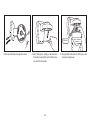
All safety and operation instructions should be read and followed before operating the unit. Retain instructions for future reference.
Heed Warnings - Adhere to all warnings on the unit and in the operating instructions.
Installation Cautions - Do not place this unit on an unstable stand, tripod, bracket, or mount. The unit may fall,
causing serious injury to a person and serious damage to the unit.
Cleaning - Unplug the unit from the outlet before cleaning. Follow any instructions provided with the unit. Generally, using a damp cloth for cleaning is sufficient. Do not use liquid cleaners or aerosol cleaners to protect unit from liquid has been spilled or an object has fallen into it.
Don't please mount the unit on the unstable bracket, wall or ceiling to avoid accidence happening.
Service- Do not attempt to service this unit yourself as opening or removing covers may expose you to dangerous voltage or other hazards. Refer all servicing to qualified service personal.
No matter camera is on or under working, never to expose the camera to sun light or strong illuminate object
otherwise the permanent damage will be caused to its CCD.
Please don't repair unit parts optionally when it is wrong. First referring to operation instruction to find out defect or call for the qualified service personnel authorized by our company.
The equipment can't endure big shock or placed on the vibrating platform.
This equipment shouldn't be exposed in the moisture in the long run or in the surrounding full of incentive or
caustic gas.
1
CHAPTER 1: GENERAL INFORMATION
Intelligent speed dome camera gives you a comprehensive view that
you simply can't get from a fixed camera. Our technology delivers the
details of your target, zooming in or out in less than a second to capture
the image you need. Zoom-Adjusted Programming ( ZAP) lets you pan, tilt
and zoom in every direction, automatically adjusting the pan and tilt speed in proportion to the zoom so that you don't have to. Additional features
like Pattern, Group and Swing enable you to conduct a virtual patrol of
your facility whether or not someone is manning the controls. Auto-focus
with manual override renders a clear picture every time. From the most
distant corner of a parking garage to the maze of hallways throughout a
building, our speed dome cameras will take you everywhere you need
to see.
Camera Specification
CCD Sensor: 1/4" Sony Super HAD or Exview CCD
Zoom Ratio: 27X or 18X optical zoom 10X or 12X digital zoom
Powerful Pan/Tilt Functions
Max. 400/sec high speed Pan/Tilt Motion.
Using Vector Drive Technology, Pan/Tilt motions are accomplished in a
shortest path. As a result, time to target view is reduced dramatically
and the video on the monitor is very natural to watch.
For jog operation using a controller, since ultra slow speed 0.05/sec can
be reached, it is very easy to locate camera to desired target view.
Preset, Pattern, Swing, Privacy Mask, Group Functions and More
Max. 128 sets of position and zoom magnification are designated and
stored as Presets. For each Preset,additional information such as Dwell
time (pause time in Group action when camera reaches to a certain Preset position), Alarm action and area Label can be assigned independen-
tly to meet to your requirements.
Max. 8 set of Swing action can be stored. This enables to move camera
repetitively between two preset positions with designated speed.
Max. 4 of Patterns can be recorded and played back. This enables to
move camera to follow any actions operated by joystick as closely as
possible.
Max. 8 set of Group action can be stored. This enables to move camera
repetitively with combination of Preset or Pattern or Swing. A Group is
composed of max. 20 entities of Preset/Pattern/Swings.
Max. 8 of Privacy masks can be located wherever it is required to protect
private life.
PTZ Control
With RS-485 communication, max. 255 of cameras can be controlled at
the same time
2
CHAPTER 2: SPECIFICATIONS
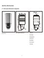
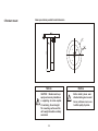
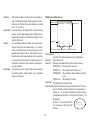
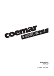
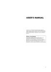
2.1 Indoor speed dome camera configuration
7
1
2
3
4
6
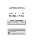
Product Photo
Indoor Speed Dome Dimension
1. Rj45 Jack
2. Mount Base
3. Dome Housing
4. Dome Cover
5. Black Shield
6. Zoom Camera
7. Rj45 cable
3
5
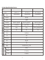
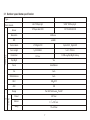
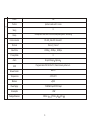
2.2 Indoor Speed Dome Specifications
Type
Zoom module
Sensor
CNB 22X color
SONY 18X color
SONY 18X Day/night
1/4"Super Had CCD
1/4"Super Had CCD
1/4"IT EXVIEW CCD
Resolution
480 Lines
48dB
S/N
Camera
Zoom Ratio
Optical 22X Digital10X
Optical 18X Digital12X
Optical 18X Digital 12X
Focal Length
f 3.9-85.8mm
f 4.1-73.8mm
f 4.1-73.8mm
Illumination
0.5Lux
0.7Lux
Day/Night
No
No
Focus
Auto/Manual
Iris
Auto
White Balance
Auto
BLC
ON OFF
AGC
Range
Speed
P/T
ON
o
Pan 360 Continuous Tilt 90o
400 o/sec
Preset
Manual
0.1 o
Swing
15 o
4
180 o/sec
60 o/sec
0.002Lux Day/Night Mode
Yes
P/T
Preset
128
Pattern
4 Patterns and each 1 minute
Swing
8
Group
8Groups and each with 20 action like preset,pattern and swing.
Communication
RS-485
Pelco-D
Protocol
Baud Rate
Max 255 Camera ID
2400bps
4800bps
OSD
9600bps
8
Privacy Mask
Alarm
Pelco-P
8Input/4Output
Optional
Programmable OSD for Pan/Tilt,Zoom Camer,Pattern etc. setting
No
Blower/Heater
o
0 C+50 oC
Temperature
95%
Moisture
Power Suplly
110-240VAC Input/12V DC Output
Consumption
20W
Dimension
215mm L
5
175mm W
235
H
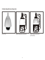
3.Outdoor Speed Dome configuration
Product Photo
Outdoor speed dome dimension
6
Outdoor speed dome dimension
(with Sunshield)
3.1 Outdoor speed dome specification
Type
Zoom moudle
Sensor
LG 27X Day/night
SONY 18X Day/night
1/4"Super Had CCD
1/4"IT EXVIEW CCD
480Lines
Resolution
48dB
S/N
Camera
Zoom module
27X Digital10X
Optical18X Digital12X
Focal Length
f 3.25-88mm
f 4.1-73.8mm
Illumination
0.01Lux
0.002Lux Day/Night mode
Day/Night
Yes
Focus
Auto/Manual
Iris
Auto
White Balance
Auto
BLC
ON OFF
AGC
Range
Speed
P/T
ON
o
Pan 360 Continuous Pan90 o
400 o/sec
Preset
0.1 o
Manual
Swing
15 o
7
180 o/sec
60 o/sec
Preset
128
Pattern
4patterns and each 1 minute
Swing
8
Group
8Groups and each with 20 actions,like preset,pattern and swing
P/T
Communication
RS-485
Pelco-D
Protocol
Baud Rate
2400bps
Pelco-P
4800bps
9600bps
8
Privacy Mask
Alarm
Max 255 Camera ID
8Input/4Output
Optional
OSD
Programmable OSD for Pan/Tilt, Zoom Camera,pattern etc .
Blower/Heater
Built in
Temperature
-35 oC+50 oC
95%
Moisture
Power Supply
110-240VAC Input/12V DC Output
Consumption
Package Dimension
20W
215mm
8
L
175mm
W
235 H
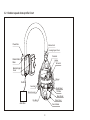
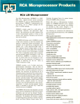
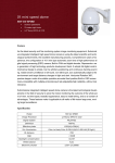
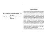
3.2 Outdoor speed dome profile Chart
Power Box
Bracket Joint
Housing Upper Cover
Termostat
Heater
Bracket Mount
Base
Termostat
Bracket Upper
Cover
Blower
Rs485
Sunshield
Shield Mount
Tilt Motor
Dome Housing
Black Shield
Dome Cover
Pan Motor
Alarm Box
Zoom Module
9
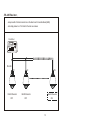
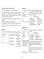
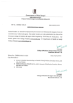
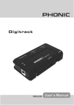
CHAPTER 3:Alarm Board connection
Alarm Board connection
ACB
Power
Video Cable
Monitor
Video
RS-485 Cable
Alarm Input Cable
Controller
Alarm Sensor
Alarm Output Cable
220VAC/12VDC
Siren
ACB=Alarm & Connection Board
Alarm Board connection Drawing
10
Alarm Board Connection Chart
Power Cable
Power Board
Power
Video Cable
Monitor
Video
RS-48 5Cable
Controller
Alarm Input Cable
Alarm Output Cable
Alarm Sensor
220VAC 12VDC
Siren
ACB=Alarm & Connection Board
Alarm Board Connection Chart
11
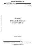
Alarm Board Connection (ACB)
12V Power Input
1
ON
120 Terminal Resistor
B A
G 12V
B A
RS485
NO NC
No.4 Alarm Output Choice
NC off NO on
No.3Alarm Output Choice
NC off NO on
S2
S1
A1 A2 A3 A4 G A5 A6 A7 A8
NC NO
O1
Alarm Input 1-8
O2
G
O3
O4
Alarm Output 1-4
1 2 34G5 67 8
G
Alarm Output1
Alarm Output4
Alarm Input 1-4
Alarm Input5-8
Alarm Output2
Alarm Output3
12
.RS-485 Resistor
Jumper switch of terminal resistor is on the Alarm and Connection Board(ACB).
Just simply make it on "on" state for the last one camera.
Controller
RS-485
#1
Rs485 Resistor
OFF
#2
#N
Rs485 Resistor
Rs485 Resistor
OFF
ON
13
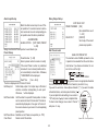
CHAPTER 4:PROTOCOL AND CAMERA ID SETTING
Protocol Setting
ON
ON
NT/PAL
ZM1
ON
ON
ON
Protocol
1
Protocol and
Baud Rate
2
3
4
5
6
ON
PRO0
(Pin1)
PRO1
(Pin2)
DIP switches on the PCB to configure the camera
OFF
ON
OFF
ON
OFF
OFF
ON
ON
ID and communication protocol. There are 2 DIP
Protocol Setting
Protocol and Baud Rate Setting
switches on the PCB,positions shown as above.
Notice
Factory default protocol is PELCO-D
Baud Rate is 2400bits/sec,
Please confirm if the DIP reach the signated
position.
14
1
2
3
4
5
6
Reserved
Switch State
Before you install the camera, you should set the
ZM0
PRO2
PRO1
PRO0
ID Dip
NT/PAL
ZM1
ZM0
PRO2
PRO1
PRO0
ON
Protocol/Baud
PELCO-D, 2400 bps
PELCO-D, 9600 bps
PELCO-P, 4800 bps
PELCO-P, 9600 bps
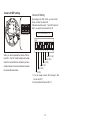
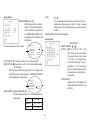
Camera ID DIP setting
Camera ID Setting
By changing the DIP switch, you can set the
binary number for camera ID.
ON state of switch means '1' and OFF means '0'.
Ex) If you want to set camera ID as 10.
ON
ID : 0+2+0+8+0=10
Camera ID DIP
ON
1
When you want to operate the camera. The Camera ID in this DIP switch setting must be indential to the camera ID of the controller.If you have
multiple cameras, it is recommended to memorize
the camera IDs and location
2
3
4
5
6
7
8
32 (if 'ON')
16(if 'ON')
8(if 'ON')
4(if 'ON')
2(if 'ON')
1(if 'ON')
1. You can assign camera ID in the rage 1~255.
Do not use ID '0'.
2. Factory default of Camera ID is '1'.
15
CHAPTER 5:INSTALLATION
5.1 Intallation Notice:
1. Installation and operation should be executed by qualified
service personnel or designated personnel under the condition adapting to the local regulation.
2. Be careful and not leave finger print on the clear housing,
that will affect the picture quality.
3. Please clean the dome cover to get good quality picture
using soft cloth when you find the picture is getting dim.
16
5.2 Indoor speed dome Installation
A.Ceiling Mount
Notice
4- 5
127EQS
109
30
CAUTION: Mounts must be properly and securely installed on
a supporting structure capable
of sustaining the unit weight.
The mounting surface and the
unit's weight should be carefully
considered
Notice
22
180
140
17
Before install, please wear
attached white glove to avoid
blur or pull dome cover so as
to effect quality of picture.
32
Steel wire
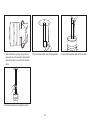
1. For cabling,make a hole sized ablout 32mm on
the celing.
2.If necessary, use a wood board to strengthen
the ceiling and fix the ceiling mount onto the
surface of the ceiling using the screws included.
18
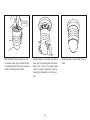
3. Take off the dome cover by turning anticlockwise and set up the camera ID and protocol.
Steel wire
4.After finishing the cabling on the Alarm and
Connection board, plug the RJ45 terminal
into the RJ45 Jack on the camera mount base.
(Refer to the ACB connection chart)
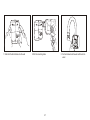
5. Wearing the glove and holding the camera
body, aim the 3 mounting clips on the mount
base at the 3 slots on the ceiling bracket.
Twist the camera clockwise and it will be
fixed onto the bracket after a " click" is sounded.
19
6. Recover the dome cover and finish the installation.
B.Wall Mount
116
110
145
145
40
45
86
58
42
52
76
218
Notice
The position must firm and
endure more than 5 time weight of camera and mount bracket, otherwise the quiver
picture will be caused.
20
Notice
Before install, please wear
attached white glove to avoid
blur or pull dome cover so as
to effect quality of picture.
1. Stick the Position-Paster onto the wall
2.Drill the mounting holes
21
3. Fix the bracket base onto the wall using the
screws included.
Steel wire
4.Pass the RJ45 cable through the bracket.
5. After finishing the cabling on the Alarm and
Connection board,(Refer to the ACB connection chart) fix the bracket.
22
6. Plug the RJ45 cable into the RJ45 Jack on the
camera mounting base.
7. Wearing the glove and holding the camera
body, aim the 3 mounting clips on the mount
base at the 3 slots on the ceiling bracket. Twist the camera clockwise and it will be fixed
onto the bracket after a click is sounded
8. Take off the dome cover by turning anticlockwise and set up the camera ID and protocol.
Recover the dome cover and finish the installation
23
9. Finished installation.
Indoor speed dome pendent bracket dimension
180
15
2
180
16
30
4 - 16
127EQS
200
C.Pendent mount
Notice
CAUTION: Mounts must be properly and securely installed on
a supporting str ucture capable
of sustaining the unit weight.
The mounting surface and the
unit's weight should be carefully
considered
24
Notice
Before install, please wear
attached white glove to avoid
blur or pull dome cover so as
to effect quality of picture.
1. Take off the dome cover by turning anticlockwise and set up the camera ID and protocol.
Recover the dome cover and finish the installation.
2. Fix the bracket bottom onto the ceiling surface
4. Use the extension pole to adjust the length.
25
3. Connect all the external cable and fix the dome
5.3 Outdoor Speed Dome Installation
138
59
300
248
42
Cable hole
91
Outdoor speed dome wall bracket dimension.
Notice
The position must firm and
endure more than 5 time weight of camera and mount bracket, otherwise the quiver
picture will be caused.
26
Notice
Before install, please wear
attached white glove to avoid
blur or pull dome cover so as
to effect quality of picture.
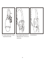
1. Stick the Position-Paster onto the wall
2. Drill the mounting holes
27
3. Fix the bracket onto the wall with tools included
Cushion
Cushion
4. Wearing the glove, take off the dome cover
Steel wire
5. Take the camera protection cushion out of
the camera.
28
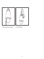
6. Take off the black shield and set up camera
ID and Protocol
7. Recover the black shield and the dome
cover.
8. Pass the RJ45 cable through the bracket
29
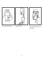
9. Put the camera into the wall mount bracket
10. Fix the dome camera with the 3 screws
using the screw driver included
11. After connecting all the cables ( Refer to the
ACB connection chart ), fix the box cover
using the screws
30
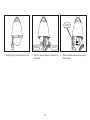
8. Fasten the box cover.
13. Fasten the screws to fix the dome cover.
14. Finish the installation.
31
5.2 Pendent mount
191
30
59
Cable hole
342
138
42
Pendent Bracke Dimension
Notice
The position must firm and
endure more than 5 time weight of camera and mount bracket, otherwise the quiver
picture will be caused.
32
Notice
Before install, please wear
attached white glove to avoid
blur or pull dome cover so as
to effect quality of picture.
1. Stick the Position-Paster onto the wall
2.Drill the mounting holes
33
3. Fix the bracket mounting base onto the surface of the ceiling.
Cushion
Cushion
4. Wearing the glove, take off the dome cover
5.
Steel Wire
Take the camera protection cushion out of
the camera.
34
6.
Take off the balck shield and set up camera
ID and protocol.
7. Recover the black shield and the dome cover.
8. Fasten the screws to fix the dome cover.
35
9. Pass the RJ45 cable through the bracket.
10. Put the camera into the wall mount bracket
11.Fix the dome camera with the 3 screws using
the screw driver included
36
12.After connecting all the cables ( Refer to the
ACB connection chart ), fix the box cover
using the screws
13. Fasten the box cover.
14. Finish the installation.
37
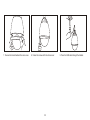
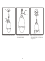
5.4 Outdoor Sunshield Installation
1.Take off the upper cover of the dome housing
2. Put the sunshield over the dome housing.
38
3. Make sure the three screw holes are in same
position
CHAPTER 6: Speed Dome Control by Keyboard
The various function of speed dome can be achieved by the keyboard
compatible with the speed dome, Due to the different desig n of manufacturers, the operation may be different. Please refer to the user manual
supplied by the manufacturers. ( Advice: Using our keyboard to get full
functions of the speed dome.)
6.1. Select Address of PTZ Dome Camera [N] + [CAM]
Description: N = No. of camera from 1 to 255
Function: Select the address of the camera to be controlled.
For Example: To Select Camera number 2, just follow below
operation: [2] + [CAM]
And you can also press -1 key to choose previous camera or press+1
key to select next camera.
6.2. Pan/tilt and Lens control:
Select a specific camera, move the joystick to control PTZ dome's
Pan/tilt moving and press "I+" "I-" "F+" "F-" "Z+" "Z-" to control the
lens.
6.3. To set preset position[F1]+[ 8 ] +[N] +[PRE]
Description: N =No. of preset position from 1 to 128.
Function: Store current position and refer it as No. N preset position.
For Example: To set Camera number 2's preset 2, just follow below
operation: Select Camera number 2 and move it to your desired
position and zoom ratio as below:
[2]+ [CAM] then [F1]+[8]+[ 2] +[PRE]
6.4. Call the Preset position[N] +[CALL]
Description:N =No. of preset position from 1 to 128.
Function: Move the camera to the position of No. N preset position.
For Example: To call Camera number 2's preset 2, just follow
below operation: [2]+ [CAM] then [2] +[CALL]
6.5. Below operation is for our speed dome camera only
1) OSD menu operation
[95] + [CALL] to enter into the OSD menu for speed dome
camera setting, tilt your joystick UP or DOWN to select a menu item
and use "F+" key to confirm or "F-" key to cancel.
2) Pattern
131-134 +[CALL] to run Pattern 1-4
Use OSD Menu to set or delete a Pattern.
3) Group
141-148 + [CALL] to run Group 1-8
Use OSD Menu to define or delete a Group.
4) Swing
151-158 + [CALL] to run a Swing
Use OSD Menu to define or delete a Swing,
.
* For more details about speed dome control, please refer to our
Speed Dome Camera User Manual
39
CHAPTER 7: Speed Dome Control by OSD
Check Proceedings before Operation
Check the cable connection carefully before input power.
The camera ID of the controller must be identical to that of the target
camera. The camera ID can be checked by reading DIP switches in the
camera
If your controller supports multi-protocols, the protocol must be changed
to match to that of the camera.
Since the operation method can be different for each controller available,
refer to the manual for your controller if camera can not be controlled
properly. Major operations of this manual are based on the standard
Pelco Controller.
Since Preset 95 is reserved to start the OSD menu, this can not be used
as regular Presets. Therefore, the description "Preset 1~128" always
means excluding Preset 95 in this manual.
OSD Menu
Function:
Start Menu:
Preset
Function:
Using the OSD menu, Preset, Group and Alarm I/O function
can be configured for each application.
After type the numeric key 95, press the swing pattem key
to start OSD menu.
Max. 127 positions can be stored as Preset position. 1--128
number can be designed on the screen menu beside 95
numeric key. The combination the preset key on keyboard
and numeric key speedup the store and use of preset and
realize the modification to the preset default by keyboard.
(such as preset label blank,3 second dwell time, relay output
closing.)
Setup Preset: Select the desired camera to adjust to the state of given position. First, press F1 key , then press 8 numeric key and
input preset number, lastly, press RRE key.
Running Preset: Select the desired camera ( if the camera on the screen, can
be omitted.)First, input preset number(1-128), default number
is 1, then press CALL key to run the corresponding preset.
Delete Preset: To delete Preset, use OSD menu.
Swing
Function:
By using Swing function, we can make camera to move between 2 Preset positions repeatedly. Swing speed can be
selected from 3 steps i.e. FAST, NORMAL and SLOW. The
speed for FAST, NORMAL and SLOW mode is 60/sec, 30/sec
and 15/sec respectively.
To set Swing, use OSD menu
Set Swing:
Run Swing:
After you type a numeric key Swing No. + 10 (i.e. 11~18),
press SAL key in the controller.
40
Delete Swing: To delete swing, use OSD menu.
Pattern
Function:
Pattern enables us to save and play back the camera
motions created by using tilting the joystick. Max. 4 Patterns can be used and can be recorded during max.1 min
for a pattern.
Set Pattern: Pattern can be created by one of following two methods.
1 Using key of controller: [1~4]+ SAL key.
After you type 1~4 numeric key, press SAL key for longer
than 2 seconds to start Pattern recording.
Run Pattern: After you type 1 ~ 4 numeric key, press SAL key shortly.
Delete Pattern: Use OSD menu to delete a Pattern.
Group
Function:
The group function allows running sequence of Presets, Pattern and/or Swings. Max 8 group can be stored. Each group
can have max 20 action entities which can be preset, pattern
or swing. The group can be created, modified and deleted
using menu. Also, dwell time defined in the preset menu is
effective when group is running.
Dwell Time
PROGRAM PATTERN
1
REMAINING STORAGE 099
Preset 1
Pattern 1
Swing 1
Max 20 Entities
Set Group:
Run Group:
PRESS FOCUS NEAR TO SAVE
PRESS FOCUS FAR TO CANCEL
0/-42
x001
Move the camera using Joystick to make your pattern.
Maximum recording time is 1 min. The time remained will
be displayed by % on the screen.
To save the recording, press F+ key and to cancel the
recording, press F- key. 2. Using OSD Menu: See the
section "How to use OSD Menu".
Use OSD Menu to create a Group.
After you type a numeric key 20+Group No. (i.e. 21~28),
press SAL key in the controller.
Ex) If group number is 5, press 25 + SAL key
Delete Group: Use OSD menu to delete a Group.
Other Functions
Power Up Action: This function enables to resume the last action executed before power down. Most of actions such as Preset, Pattern,
Swing and Group are available for this function but Jog actons are not available to resume.
Auto Flip 180
If tilt angle exceeds 90, Pan is automatically turned to opposite direction (+180) to track the target continuously.
41
Park Action
This function enables to locate the camera to specific position automatically if operator doesn't operate the controller for a while. The Park Time can be defined as a interval
from 1 min. to 4 hours.
Origin Position: Using this function, the Origin position can be defined by
operator. The Pan angle display will be changed if you change the origin position. It is noted that tilt angle is not affected by this function.
Alarm I/O:
If you use optional Alarm I/O module, you can take advantage of 8 alarm input and 4 alarm output. If an external
sensor is activated, camera can be set to move to corresponding preset position. Also, the output relay can be matched to some specific preset positions to do counteractions such as turning on the light or sounding the alarm. It is
noted that the latest alarm input is effective if multiple sensors are activated.
Privacy Mask: To protect privacy, max. 8 white masks can be created on
the arbitrary position to hide objects such as windows,
shops or private house.
OSD Display of Main Screen
Preset lable
Camera ID
LABEL1234567890
CAM 01
28/ - 42
x001
O:1
I:
P/T angle and Zoom information
PRESET 001
Action title
--- 2-- 5---
Alarm information
P/T/Z Information:
Current Pan/Tilt angle in degree and zoom magnification.
Camera ID:
Current Camera ID
Action Title:
Followings are possible Action Titles and their meaning.
"SPRESETxxx ": When Preset xxx is stored
"PRESETxxx ": When camera reach to Preset xxx
"UNDEFINED": When undefined Preset number is called to
move
"SWING -xxx ": When Swing x is in action
Preset Label: The Label stored for specific Preset.
Alarm Information: This information shows current state of Alarm I/O. The character 'O' of first line stands for Output and 'I' of second line means Input. If an I/O point is ON state it will show a number
corresponding to each point. If an I/O point is OFF state, '-' will
be displayed.
O: - 2- 4
Ex) Point 1, 7 of inputs are ON and
I : 1- - - - - 72, 4 of outputs are ON state. OSD
will show
42
General Rules of Key Operation for Menu
the menu items surrounded with ( ) always has its sub menu.
For all menu level, to go into sub menu, press F+ key, to go up to upper
menu, press F---- key. If you learn by heart a rule that F£«key is always
similar to Enter key and F--- key is always Esc key, many other functions
of these keys will be easy to understand.
To move from items to item in the menu, use joystick in the Up/Down or
Left/Right.
If you want to confirm a menu item, press F+ key.
To change a value of an item, use Up/Down of the joystick in the controller.
After you change a value, press F+ key to save it or press F ---- key to
cancel it
Main Menu
SPEED DOME CAMERA high speed dome
camera
SYSTEM INFORMATION display system
information
DISPLAY SETUP
display information switch
DOME SETTING
define multi-function of camera
FACTORY RESET
resume factory
default position
Display Setup
This menu defines Enable/Disable of OSD
display on Main Screen. If an item is set to be
AUTO, the item is displayed only when the
value of it is changed.
DISPLAY SETUP
CAMERA ID
[ON/OFF]
ACTION TITLE
[ON/OFF/AUTO]
PTZ INFORMATION
[ON/OFF/AUTO]
PRESET LABEL
[ON/OFF/AUTO]
ALARM INFORMATION
[ON/OFF]
CAMERA SETUP
Setup the general functions of zoom camera
module.
CAMERA SETUP
DIGITAL ZOOM
[ON/OFF]
FOCUS MODE
[AUTO/MANUAL]
BACK LIGHT
[ON/OFF]
DAY & NIGHT [AUTO1/AUTO2/DAY/NIGHT]
By tilting joystick to Up/Down, The mode can be selected. It is noted that the
mode is effective simultaneously and Auto1 and Auto2 is about same.
WHITE BALANCE
[AUTO/SPECIAL/INDOOR/OUTDOOR/MANUAL]
LINE LOCK SYNC
[ON/OFF]
If Line lock sync is ON, video signal is synchronized
with AC power. Video can be fluctuated after setting
is changed.
RESET CAMERA
Initialize the zoom camera module
43
P/T Motion Setup
Park Action Setup
Setup the general functions of Pan/Tilt motions.
MOTION SETUP
POWER UP ACTION
[ON/OFF]
AUTO FLIP
[ON/OFF]
JOG SPEED
[FAST/NORMAL/SLOW]
The maximum jog speed is listed below
when zoom is x1. As zoom magnification is increased, the speed will be
decreased to maintain equal controllability.
FAST
0
160
/sec
This function enables to locate the camera to
specific position automatically if operator doesn't
operate the controller for a while. The Park Time
can be defined as an interval from 1 min. to 4
hours.
PARK ENABLE [ON/OFF]
PARK TIME
[1 min ~ 4 hours]
The time is displayed with "hh:mm:ss" format and you can change this by 1
min unit.
PARK ACTION [Preset 1~128]
NORMAL
0
80
/ sec
Origin Position Setup
SLOW
0
40
/ sec
You can redefine particular pan position to Origin position.
ORIGIN POSITION SETUP
ORIGIN POSITION
[ON/OFF]
SET ORIGIN POSITION If you choose this
menu, you can move
pan position by joystick and redefine Origin.
JOG DIRECTION
[INVERSE/NORMAL]
If you set this to 'Inverse', the view in the screen is
moving same direction with jog tilting. If 'Normal' is
selected, the view in the screen is moving reversely.
PARK ACTION
Activate Park function.
ORIGIN POSITION Redefine particular pan position to Origin position.
ALARM DEFINE
Match the Alarm sensor input to one of current Preset positions.
44
Alarm Input Setup
Match the Alarm sensor input to one of Preset positions. If an external sensor is activated, camera will move to corresponding preset position when this item is predefined.
ALARM DEFINE
ALARM ACTION
[NOT USED, PRESET
1 128]
Assign counteraction Preset position to each Alarm input.
Preset Setup
Preset Number [1~128]
Select a preset number to create or modify.
If the current Preset number is predefined,
camera will move to stored position and zoom automatically to check them. Otherwise,
"UNDEFINED" will be displayed.
Dwell Time
[1sec ~ 4min]
The time is displayed with "hh:mm:ss" format.
Edit Relay Out
Define Relay output. If an Output relay is ON state it
will show a number corresponding to each point.
Otherwise, '-' will be displayed.
Edit Preset Label Edit the Label for a specific Preset position. A Label
can be named with max 15 characters. This label is
automatically displayed on the upper left corner of
the screen whenever you move to the corresponding
preset position.
Edit Preset Scene Redefine current Preset scene position (i.e. PTZ).
Clear Preset
Delete current Preset data.
Relay Output Setup
EDIT RELAY OUT
PRESET NUMBER [006]
[Ex:number006 is one of
1---128]
RELAY OUT
[ON/OFF]
Set 4 relay of the current
preset output position.
Edit Preset Label
LABEL FOR PRESET 001
The inverted cursor of LABEL represents current position to be selected from the set of characters bellow. If you choose a character, the cursor will move to the right.
Current Cursor Position
Using Left / Right / Up / Down of joystick, move to an appropriate character
from the Character set. To choose that character, press the F+ key.
If you want to use blank, choose Space character (" "). If you want to delete
a character before, use back space character ("
").
2
OK
If you complete the Label editing, move cursor to
ABCDEFGHIJ
CANCEL
"OK" and press F key to save completed label.
To abort current change, move cursor to "Cancel"
and press F+ key.
Space Char.
45
Back Space Char.
Edit Preset Scene
Record Pattern
PROGRAM PATTERN [1]
Ex. Number1,ie.pattern number
selected in sup-menu
REMAINING STORAGE 99£¥time remained
means
99% of running pattern time.
PRESET NUMBER [006]
Preset Number
Ex:number006 is one
of 1 128
1. Using Joystick, move camera to desired
position and the multiple is suitable for
zoom lens.
2. By pressing F+key, save current PTZ data.
3. Press F- key to cancel PTZ data.
Pattern Setup
PATTERN SETUP
PATTERN NUMBER
1 4
Select the pattern number to edit.
If the pattern selected does not
existed, "UNDEFINED" will be
displayed as shown bellow.
PATTERN SETUP
-----------------------------PATTERN NUMBER
1
UNDEFINED
(PROGRAM PATTERN)
1. By using Joystick, move to start position with
appropriate zoom. To start pattern recording,
press F+ key. To exit this menu, press F- key.
2. Maximum recording time is 1 min. The time
remained will be displayed by % on the screen.
3. While you are moving and zooming the camera, the trajectory controlled by joystick will be
recorded at the same time.
4. If you press F+ key, the data will be saved and this menu is exited. If you
press F- key, the date recorded up to now will be abandoned and this menu is exited.
PROGRAM PATTERN If you choose this, you will go down to sub menu
to record a pattern.
CLEAR PATTERN
[ON/OFF]
46
Swing Setup
LOOP
SWING NUMBER 1 8
Select Swing number to create or
modify. If thecurrent Swing number is not defined, as shown bellow, "UNDEFINED SWING" is displayed above the 1st Position and
2nd Position.
The swing speeds is as shown bellow.
1 3
This number represents how many swing motion will be repeated when swing is executed with in a Group. However,
Swing motion will be repeated forever if you execute Swing
function.
CLEAR SWING Delete current Swing data.
Group Setup
GROUP SETUP
GROUP NUMBER 1 8
ACTION [x000, P1 P128, S1 S8, T1 T4]
x000 means no action is selected.
If you assign Preset, it will shows
P1 ~ P128. If you assign Swing,
S1~S8 will be displayed. If you assign Pattern, T1 ~ T4 will be displayed. If no action is defined, it will
be skipped when Group function
is executed.
CLEAR GROUP
Delete all of 20 Action entities. All
entities will become x000 if you execute this.
SWING SETUP
-----------------------------SWING NUMBER
1
UNDEFINED SWING
1ST POSITION
NOT USED
2ND POSITION
NOT USED
1ST POSITION
2ND POSITION
1st position can be one of 1 128 number
2nd position is one of 1 128 number settled besides
1st position.
Define 2 Preset positions for Swing motion. If you assign undefined Preset to one of these positions, "UNDEFINED PRESET"
will be displayed as shown bellow.
SWING SETUP
-----------------------------SWING NUMBER
1
UNDEFINED PRESET
1ST POSITION
PRESET 007
2ND POSITION
PRESET 002
SWING SPEED
FAST/NORMAL/SLOW
Set the Swing speed level. The swing Speeds are as
shown below.
60 /sec
FAST
NORMAL
30
/ sec
SLOW
15
/ sec
47
Setup Action
1.Select group number desired using joystick, then press F+ key to modified
2. Using Joystick, move to an entity to be modified. Then press F+ key.
3. Using joystick, select appropriate Action (x, P, S or T). Then press F+ key.
If you press F- key, the value changed will be ignored and cursor will be
jump to upper level.i.
4. Using joystick key, select appropriate Action (x, P, S or T). Then press F+
key. If you press F- key, the value changed will be ignored and cursor will
be jump to upper level.
5. If modification is completed, move to "OK" position in the right of the map and press F+ key to finish.
48
Privacy Zone Mask Setup
3. After you exit the Privacy Mask menu, you
will see the mask whenever you move to the
location privacy zone assigned. The number
in the center of the mask represents Privacy
mask number. Max. 8 zones can be located
wherever needed to protect privacy. It is noted that some mismatch or misalignment can
be aroused since OSD display is slow and its
minimum resolution is limited to a character
size.
PRIVACY SETUP
PRIVACY NUMBER 1 8
DISPLAY ON/OFF
ON/OFF
Enable or disable the
display of Privacy Zone Masking.
SET PRIVACY MASK Go down to Sub menu to program Privacy Zone.
Privacy Zone position Setup
1. By using joystick, move to the scene to
hide with mask. Adjust the zoom ratio
properly since the mask will be created
as full screen size. If you finished the
masking, press F+ key to show the mask
on the screen or press F- key to cancel.
2. After Privacy Mask is displayed, press F+
key to save or press F- key to abandon.
49
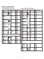
CHAPTER 8: Trouble Shooting Guide
Defect
No action,image when
connect power.
Unable to control P/T
Cause
Solution
Cable connectiong wrong
Reconnect
Change
Power damage
Power connection unfixed
Fix
Dome ID,Baud rate setup wrong
Reset dome ID,Baud rate
Protocol wrong
Change
RS485 reverse or short
Too many Domes on Rs485 Cable
Wrong Rs485 Resistor Setting
Bad Quality Rs485 Cable
Check Rs485 control cable connection
Pan Direction photoelectric Switch Fault
Initializing Failed
Image fluctuation
Image dimness
No Video Signal
Use Rs485 Distributor
Fix
Change
Fix
Fix
Tilt Direction Switch Fault
Power deficiency
Select suitable power,place power near camera or thicker cable.
Wrong DIP Setting
Modify
Video Cable connection wrong
Reconnect
Select suitable power,place power near camera or thicker cable.
Power deficiency
Line Lock Wrong Setting
Change
Focus at manual Mode
Set dome or run a preset
Housing dirty
Clean housing
Wrong Video Connection
Fix
Zoom Module FCC Cable Loose
Pull Out and Plug in
Zoom Module Fault
Change
Service- Do not attempt to service this unit yourself as opening or removing covers may expose you to dangerous voltage or other hazards. Refer
all servicing to qualified service personal.
50
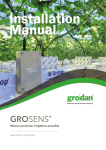
CHAPTER 9:ACCESSORIES LIST
Indoor speed dome accessroies list
Item
NO
1
Alarm and
Connection Box
2
Rj45 Cable
3
Picture
Outdoor speed dome accessroies list
Specification Unit Quantity
pcs
1
pcs
1
Ceiling Mount
Plate
pcs
1
4
User Manual
pcs
5
Glove
pcs
6
Screw
L=800mm
6mm
pcs
Wall Bracket
pcs
2
Pendent
Bracket
pcs
Item
1
Alarm Board
2
Screw Driver
3
Picture
Specification Unit
Quantity
pcs
1
pcs
1
User Manual
pcs
1
4
Glove
pcs
1
5
Paster
pcs
1
6
Screw Driver
10mm
pcs
1
7
Screw
6mm
pcs
3
8
Screw
6mm
pcs
4
9
Wall Bracket
pcs
1
3mm
1
1
4
Option
1
NO
1
2
Option
1
Pendent
Bracket
pcs
2
Sunshield
pcs
51