1
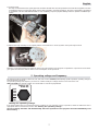
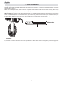
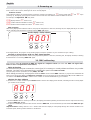
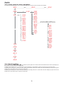
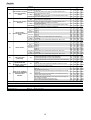
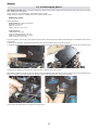
SPOT575MB
manuale
di istruzioni
instructions
manual
1^ edizione, giugno 2004
1st edition, june 2004
iSPOT 575 MB
numero di serie/serial number
data di acquisto/date of purchase
fornitore/retailer
indirizzo/address
cap/città/suburb
provincia/capital city
stato/state
tel./fax/
Prendete nota, nello spazio apposito, dei dati relativi al modello e al rivenditore del vostro iWASH 575 MB: in caso
di richiesta di informazioni, pezzi di ricambio, servizi di riparazione o altro ci permetteranno di assistervi con la massima
rapidità e precisione.
Please note in the space provided above the relative service information of the model and the retailer from whom you
purchased your iSPOT 575 MB: This information will assist us in providing spare parts, repairs or in answering any
technical enquiries with the utmost speed and accuracy.
ATTENZIONE: la sicurezza dell’apparecchio è garantita solo con l’uso appropriato delle presenti istruzioni, pertanto è
necessario conservarle.
WARNING: the fixture’s warranty is valid only if these instructions are strictly followed; therefore it is absolutely necessary to keep this manual.
3
English
Index
1. Packaging
Pag. 5
2. Transportation
,,
5
3. Important safety information
,,
5
4. Lamp: installation and substitution
,,
6
5. Operating voltage and frequency
,,
7
6. Installation
,,
8
7. Mains connection
,,
9
8. Signal connection
,, 10
9. Powering up
,, 11
10. DMX addressing
,, 12
11. Display panel functions
11.1. Function setting (FUNC)
11.2. Measure and test (MEAS)
11.3. Quick guide to menu navigation
11.4. Rapid scrolling
,,
,,
,,
,,
,,
12. DMX 512 operation
,, 17
13. Aligning the lamp in the optical path
,, 19
14. Turning on the iSPOT 575 MB without articulated movement
,, 20
15. Resetting the counter
,, 20
16. Automatic repositioning functions
,, 20
17. Opening up the projector
,, 21
18. Interchanging gobos
19. Altering the operating voltage (Reserved for technical staff)
19.1. Selecting the operating voltage
,, 22
,, 23
,, 23
20. Thermal protection
,, 24
21. Lamp circuit protection
,, 24
22. Maintenance
,, 24
23. Electronic motor alignment
,, 25
24 Error messages
,, 26
25. Spare parts
,, 27
26. Troubleshooting
,, 28’
4
13
13
15
16
16
English
Congratulations on having purchased a coemar product. You are assured of a projector of the highest quality, both in the componentry used and in the technology. We reiterate our invitation for you to complete the information on the previous page to expedite any request for service information or spares (in case of problems encountered either during, or subsequent to, installation). This
information will assist in providing prompt and accurate advice from your coemar service centre.
1. Packaging
Following the instructions and procedures outlined in this manual will ensure the maximum efficiency of this product for years to
come.
Open the packaging and ensure that no part of the equipment has suffered damage in transit. In case of damage to the equipment,
contact your carrier immediately by telephone or fax, following this with formal notification in writing.
packing list
Ensure the packaging contains:
1 iSPOT 575 MB
1 instruction manual
2 cam-lock suspension devices
2. Transportation
The iSPOT 575 MB should be transported in its original packaging or in a coemar approved flight case.
During transportation, the packaging should ensure that the articulated movement of the iSPOT 575 MB should be blocked.
3. Important safety information
Fire prevention:
1. iSPOT 575 MB utilises a Philips 575 MSD or 575 MSR/2 lamp; the use of any other lamp is not recommended and will null
and void the fixture’s warranty.
2. Never locate the fixture on any flammable surface.
3. The minimum distance from any flammable materials: 0,5 m.
4. The minimum distance from the closest illuminable surface: 2 m.
5. Replace any blown or damaged fuses only with those of an identical value. Refer to the schematic diagram if there is any doubt.
6. Connect the projector to the mains power via a thermal-magnetic circuit breaker.
Preventing electric shock:
1. High voltage is present in the internals of the unit. Isolate the projector from mains supply prior to performing any function which
involves touching the internals of the unit, including lamp replacement.
2. For mains connection, adhere strictly to the guidelines outlined in section 7 of this manual.
3. The level of technology inherent in the iSPOT 575 MB necessitates the use of specialist personnel for all service applications; refer
all work to your authorised coemar service centre.
4. A good earth connection is essential for proper functioning of the projector.
Never operate the unit without proper earth connection.
5. Do not locate the fixture in an exposed position, or in areas of extreme humidity. A steady supply of circulating air is essential.
Protection against ultraviolet radiation:
1. Never turn on the lamp if any of the lenses, filters, or the housing is damaged; their respective functions will only operate efficiently if they are in perfect working order.
Never look directly into the lamp when it is operating.
Safety:
1. The projector should always be installed with bolts, clamps, and other fixings which are suitably rated to support the weight of
the unit.
2. Always use a secondary safety chain of a suitable rating to sustain the weight of the unit in case of the failure of the primary fixing
point.
3. The external surfaces of the unit at various points may exceed 150°C. Never handle the unit until at least 10 minutes have elapsed since the lamp was turned off.
4. Always replace the lamp if any physical damage is evident.
5. Never install the fixture in an enclosed area lacking sufficient air flow; the ambient temperature should not exceed 35°C.
6. A hot lamp may explode. Always wait for at least 10 minutes to elapse after the unit has been turned off prior to attempting to
replace the lamp.
Always wear suitable hand protection when handling lamps.
Protection rating against penetration by solids and liquids:
1. The projector is rated as an ordinary device. Its protection rating is IP 20
5
English
4. Lamp: Installation and replacement
The iSPOT 575 MB utilises a Philips 575 MSD or Philips 575 MSR/2 575W lamp with a GX 9.5 lampbase.
The lamp is available from your coemar service centre:
Philips 575 MSD
coemar cod.
power
luminous flux
colour temperature
base
approximate lamp life
105215
575 w
43.000 lm
6000° K
GX 9,5
3000 hours
Philips 575 MSR/2
coemar cod.
power
luminous flux
colour temperature
base
approximate lamp life
105245/2
575 w
49.000 lm
7.200° K
GX 9,5
1000 hours
Attention
Disconnect mains prior to opening up the unit.
The fixture’s internal temperature can reach 250° C after 5 minutes with a maximum peak of 350° C; ensure that the lamp is cold
prior to attempting removal. The fixture should be allowed to stand and cool for 10 minutes prior to its removal.
Both MSR and MSD lamps are part of the mercury vapour family of discharge lamps and must be handled with great care. The lamps
operate at high pressure, and the slight risk of explosion exists if operated over their recommended lamp life.
We recommend, therefore, that the lamp be replaced within the manufacturer’s specified lamp life.
installing the lamp
1) Using a Philips head screwdriver, loosen the 2 screws (A) which affix the lamp assembly, located at the rear of the projector.
2) Remove the lamp assembly (B).
3) Locate the lampholder (C)
6
English
4) Insert the lamp.
The lamp is manufactured from quartz glass and should be handled with care; always adhere to the instructions supplied in the lamp’s packaging. Never touch the glass directly, use the tissue provided in the lamp’s packaging. The GX 9.5 lampholder is symmetrical
in construction. DO NOT USE UNDUE FORCE. In case of difficulty, inspect for physical damage and then repeat the installation procedure.
5) Replace the lamp assembly into its original position and refasten the 2 screws (A) which were previously loosened.
Attention: we recommend that you realign the lamp in the optical system of the projector to optimise the output and to avoid damage to gobos and dichroics. Refer to section 13 for a description of this procedure.
5. Operating voltage and frequency
The projector is able to operate at either 100, 115, 208, 230 or 240 V. Coemar presets (barring specific requests) an operating voltage of
240v at a frequency of 50 Hz.
The operating voltage and frequency are noted on a sticker nearby the voltage selector on the base of the unit.
iSPOT 575 MB can operate at either 50 or 60 Hz with no need for any adjustments.
factory set
main at:
100V
115V
208V
230V
240V
50Hz
60Hz
altering the operating voltage
If the preset voltage does not correspond with the conditions in your particular country of operation, follow the instructions in the
appropriate section of this manual, section 15. Altering the operating voltage.
Incorrect voltage selection will detrimentally affect the operation of the projector and will immediately void
the warranty.
7
English
6. Mechanical installation
installation
iSPOT 575 MB may be suspended or floor mounted.
For the purposes of floor mounting, the iSPOT 575 MB is fitted with four pads on the base. For suspending the fixture
from lighting truss, coemar has included two cam-lock devices (A).
A
The two cam-lock devices may be installed on the base of the iSPOT 575 MB. The devices are 1/4 turn locking. To install them,
make sure that they are correctly seated in the appropriate slots in the base of the unit.
A
A
If the fixture is to be suspended, we recommend the use of appropriate C clamps which are capable of comfortably sustaining the
weight of the fixture. The C-clamps are fitted to the central shaft of the cam-lock devices.
Attention
Always use 2 clamps to suspend the projector
The structure from which the unit is hung should be of sufficient rating to hold the weight of the unit and should also be sufficiently
rigid so as to not move or shake whilst the iSPOT 575 MB moves during its operation.
8
English
safety chains
The use of a safety chain fixed to the unit and to the primary suspension structure is highly recommended to protect against the
accidental failure, however unlikely, of the primary suspension points.
If using an after-market safety chain not manufactured by coemar, ensure that it is of a sufficient rating to hold the weight of the unit.
The safety chain is attached by means of the two holes B located in the base of the unit as shown in the diagram.
B
protection against liquids
The projector contains electric and electronic components that must not come into contact with water, oil, or any liquid.
movements
The projector has an articulated movement of 360° in the base and 252° through its yoke; DO NOT obstruct the articulated movement in any way.
risk of fire
Each fixture produces heat and must be installed in a well-ventilated position. The minimum recommended distance from flammable material is: 0.5m. Minimum distance from the object being illuminated is: 2m.
forced ventilation
You will note that the projector contains several cooling fans and vents located in the base and the yoke. Under no circumstances
should these be obstructed.
Obstruction of any of these points will result in the over-heating of the unit, detrimentally and seriously affecting the proper operation of the fixture.
ambient temperature
Never install the projector in locations where there is insufficient flow of circulating air; the ambient temperature should not exceed
35°C.
9
English
7. Mains connection
preparing the cable
The mains cable provided is thermally resistant, having VDE approval and complying to the most recent international standards, namely IEC
331, IEC 332 3C,CEI 20 35.
NB: In case of cable replacement, similar cable with comparable thermal resistant qualities must be used exclusively (cable 3x1,5 ø
external 10 mm, rated 300/500V, tested to 2KV, operating temperature -40° +180°, coemar cod. CV5309).
mains connection
iSPOT 575 MB may operate at 100V-115V-208V-230V-240V at 50 or 60Hz (operating voltage should be selected as discussed in
section 5 of this manual). Prior to connecting the unit to your mains supply, ensure that the model in your possession correctly matches the mains supply available to you. For connection purposes, ensure that your plug is of a suitable rating: : 4.5 amps at 230V,
8 Amps at 115 V. Locate the mains cable which exits the base of the unit and connect as shown below:
marrone - brown
blu - blue
fase/live
neutro/neutral
giallo/verde - yellow/green
massa/ground
alimentazione
main
protection
The use of a thermal magnetic circuit breaker is recommended for each iSPOT 575 MB.
A good earth connection is essential for the correct operation of the fixture. Strict adherence to regulatory norms is strongly recommended.
10
English
8. Signal connection
Control signal is digital and is transmitted via two pair screened ø 0,5cable.
Connection is serial, utilising XLR 3 male and female sockets on the base of the iSPOT 575 MB, labeled DMX 512 In and Out
(see diagram).
Pin connection conforms to international standards:
pin 1= screening 0 volt
pin 2= data pin 3= data +
Should your DMX 512 controller utilise only XLR 5 sockets, pins 4 and 5 should not be connected.
factory set
main at:
100V
115V
208V
230V
240V
50Hz
60Hz
dmx 512
pin1: gnd
pin2: data–
pin3: data+
out
Power
out
T5A @230V
T12A @115V
T2A @230V
T3A @115V
lamp: 575W MH
type: MSR/2
or MSD
base: GX 9,5
230V
ie: 3,5A
ie max: 5A
115V
max temp ext:
ta max:
il: 6,95A
cosϕ
2m
IP 20
ie: 7A
ie max: 10A
150°C
made in italy
by coemar spa,
Castel Goffredo
Mantova - Italy
2m
35°C
in
0,98
serial number:
in
Controller
Standard
DMX 512
OUT
3
factory set
main at:
100V
115V
208V
230V
240V
50Hz
60Hz
dmx 512
pin1: gnd
pin2: data–
pin3: data+
T5A @230V
T12A @115V
out
out
Power
2
1
T2A @230V
T3A @115V
lamp: 575W MH
type: MSR/2
or MSD
base: GX 9,5
230V
ie: 3,5A
ie max: 5A
115V
max temp ext:
ie: 7A
ie max: 10A
made in italy
by coemar spa,
Castel Goffredo
Mantova - Italy
ta max:
il: 6,95A
cosϕ
2m
IP 20
150°C
35°C
2m
in
0,98
serial number:
in
Ad altri iSPOT 575 MB
Connect to other iSPOT 575 MB
Ensure that all data conductors are isolated from one another and the metal housing of the connector.
Note: the housing of the cannon XLR 3 or 5 must be isolated
11
English
9. Powering up
After having followed the preceding steps, turn on the projector via the power button. upon powering up, the projector will perform a reset on all its motors, allowing them to be correctly aligned.
Software version
Three software systems are located within the projector, located in the display pcb “D” and the master pcbs“A” and
powering up, the display of the projector will for a few seconds show the software versions installed in the unit.
For example, the Ispot 575 MB may show:
“B”. Upon
D 1.10 (display software “D” version 1.10.)
A 1.02 (master software installed in location “A” version 1.02.)
B 1.01 (master software installed in location “B” version 1.01.)
DMX reception
After having displayed the software versions, the projector will perform a reset and, following this, the display will stay on in a fixed
mode, indicating that the fixture is correctly receiving DMX 512 signal.
function display /
function display
AOO1
e n ter
+
en
t er
enu
+
m
m
enu
If the display flashes, the projector is not receiving signal. Check the operation of your controller and your cabling.
turning on the projector with no dmx signal present
After having displayed the software versions, the projector will perform a reset and, following this, the display will flash, indicating
that the fixture is not receiving DMX 512 signal.
10. DMX addressing
Each projector utilises 22 channels of DMX 512 signal for complete control (see section 12. DMX 512 signal functions for more comprehensive information)
DMX addressing
To ensure that each projector accesses the correct signal, it is necessary to correctly address each fixture. Any number
between 1 and 490 can be generated via the multifunction panel of the iSPOT 575 MB.
This procedure must be carried out on every iSPOT 575 MB.
When initially powered up, each projector will show A001 which indicates DMX address 1; a projector thus addressed will
respond to channels 1 to 22 of your DMX 512 controller. A second projector should be addressed as 23, a third as 45 and so
on until the final iSPOT 575 MB, in relation to the number of channels addressable by your controller.
altering the dmx address
1) Press the + or - button until the required DMX address is located. The display panel will flash, indicating that the currently displayed address is not recorded.
AOO1
enu
e n ter
+
m
en
+
t er
m
enu
2) Press the enter button to confirm your selection; the display panel will stop flashing and the fixture will now respond to the newly
assigned DMX 512 address.
3) To gain an understanding of the functions of each channel of DMX 512, we recommend that you read section 12. DMX 512 operation
Important Note: holding down the + or - buttons will cause the display to scroll quickly through the channel numbers at an
increased speed, allowing a faster selection to be effected.
12
English
11. Display panel functions
By using the display panel located on the iSPOT 575 MB you are able to display and set function information and to alter various
configuration parameters.
Incorrectly altering the coemar factory settings may vary the functioning of the projector, causing it to not respond to external DMX
512 control signal; please read and familiarise yourself with the following information very carefully prior to altering any selections.
NOTE: the ☞ symbol is used in the following table to indicated the action of pressing the appropriately labeled button.
11.1. Function settings (FUNC)
The projector is able to have several function settings altered in order to personalise its use to your requirements.
AOO1
☞
menu
FUNC
functions menu
The unit gives the possibility to vary some functions
settings and to apply personalizations.
☞
enter
☞
+/-
☞
+/-
☞
+/-
☞
+/-
☞
PD IR
enter
pan movement inversion
To reverse horizontal movement direction of the beam on DMX level variation.
☞
enter
tilt movement inversion
To reverse vertical movement direction of the beam on DMX level variation.
TD I R
☞
OPTO
enter
optic sensor de-activation
To deactivate the optic sensor function with return in position of the unit
if accidentaly knocked out of place.
☞
LAMP
enter
FANS
enter
lamp control
To disable on/off control of the lamp by DMX signal
fans control
Fans status control through PCB (Strd) or fans always on (On).
☞
☞
+/-
☞
enter
CW
☞
☞
+/enter
CCW
counter-clockwise
☞
☞
+/enter
CW
clockwise
☞
☞
+/enter
CCW
counter-clockwise
☞
☞
+/enter
ON
sensors activation
☞
☞
OFF
+/enter
sensors deactivation
☞
☞
+/enter
STRD
switching on through DMX 512
☞
☞
+/enter
ON
lamp always on
☞
☞
+/enter
STRD
fans speed control depending on
clockwise
external temperature and lamp status
☞
+/☞
+/-
☞
+/☞
+/☞
+/☞
+/☞
+/-
☞
+/-
☞
+/-
☞
+/-
☞
DISP
enter
reverse display
To reverse the display reading depending on mounting position (base or
suspended)
☞
+/☞
+/-
☞
DEMO
enter
IRIS
enter
☞
iris
iris function mode
Sflashing
URE
☞
enter
☞
enter
☞
enter
-–-–-–-–
demo program activation
☞
+/-
LIN
OFF
pulse iris
☞
enter
linear iris
☞
+/☞
X.Y
enter
Pan and Tilt setting
Function without pan/tilt movement
☞
+/-
LIN
OFF
pulse iris
☞
enter
☞
enter
linear iris
☞
+/☞
PAN
Pan movment control
Pan mode: reduction of angle rotation from 540° to 400°
enter
☞
+/☞
+/-
SHUT
☞
Shutter setting
2 Different modes of shutter function
enter
☞
+/☞
+/-
☞
+/-
reversed, base upwards
-–-–-–-–
☞
demo program
To see all the unit’s functions dell’apparecchio.
☞
reset activation
☞
enter
enter
to switch the display off
(☞ any keys to switch it on)
enter
DFSE
AA
OFF
enter
default functions setting
to set all the functions at the original values, but for the alignment
operations and for the recorded programs.
enter
base downwards
☞
LED
RESE reset
Reset function.
display control
To disable display visualisation.
☞
ON
fans always on
AA
☞
+/-
ID
☞
ID number setting
To set the unit’s ID number from 0(no ID, to 250).
enter
inverted display
13
540
400
Pan 400°
Pan 540°
Mmode
O D1. !
M mode
O D 2. 2
1 --2 5 0
numeric value
☞
enter
☞
enter
☞
enter
☞
enter
☞
enter
☞
enter
English
As stated in the table above, the iSPOT 575 MB is able to invert the display on the projector should it be installed base down.
The display will appear as shown in the diagram below.
function display /
function display
AOO1
enu
e n ter
+
+
m
en
t er
m
To change DMX address use (+) and (--);
to record press (enter). To select a function
press (menu). To escape a function press (menu) twice.
enu
To change DMX address use (+) and (--); to record press
(enter). To select a function press (menu).
To escape a function press (menu) twice.
AOO1
☞
menu
FUNC
☞ ☞
D I S P display reverse
enter + o–
☞
+ o–
14
AA
AA
☞
+ o–
☞
enter
☞
enter
English
11.2. Measure and test (MEAS)
The electronic pcbs of the iSPOT 575 MB allow for various digital and auto-diagnostic measurements to be made.
You may, in this section, record a home position to which the projector will return when it is turned on in the absence of dmx signal.
AOO1
☞
menu
+/- MEAS
FUNC ☞
☞
enter
TEST
test
function test
☞
enter
☞
+/-
PAN
TILT
tilt movement
DIMM
dimmer activation
SHUT
shutter activation
IRIS
iris activation
STZO
step zoom activation
FOCU
focus activation
GOB1
gobo wheel 1 selection
GBP1
gobo 1 positioning
GBR1
gobo 1 rotation
GOB2
gobo wheel 2 selection
GBP2
gobo 2 positioning
GBR2
gobo 2 rotation
PRIS
prisma activation
COL1
colour wheel 1 selection
COL2
colour wheel 2 selection
STOR
to record the position of the unit and of its internal
☞
enter
pan movement
☞
+/☞
+/☞
+/☞
+/☞
+/☞
+/☞
+/☞
+/☞
+/☞
+/☞
+/☞
+/☞
+/☞
+/☞
+/☞
+/-
☞
enter
☞
enter
☞
enter
☞
enter
☞
enter
☞
enter
☞
enter
☞
enter
☞
enter
☞
enter
☞
enter
☞
enter
☞
enter
☞
enter
☞
enter
☞
enter
+/0/255 ☞
+/0/255 ☞
+/0/255 ☞
+/0/255 ☞
+/0/255 ☞
+/0/255 ☞
+/0/255 ☞
+/0/255 ☞
+/0/255 ☞
+/0/255 ☞
+/0/255 ☞
+/0/255 ☞
+/0/255 ☞
+/0/255 ☞
+/0/255 ☞
+/0/255 ☞
☞
SURE enter
components. If DMX signal is not applied, the recorded
setting will appear at the end of reset operation when
the unit is switched on.
☞
+/☞
+/-
TEMP
VFAN voltage to fans
to measure the DC voltage to the fans located in the unit. Values
temperature
to measure the internal temperaturein C°
☞
enter
58C
13.8V
voltage measurement
temperature measurement
☞
enter
higher than 13,8V are anomalous.
☞
+/-
☞
+/☞
+/-
DMIN
DMX value on each channel
reading of DMX value (0/255), received by each of the 22
channels on DMX 512 line.
☞
enter
☞
+/-
CH01
CH22
to channel 22
24.50
value reading
f r o m channel 1
RATE
☞
enter
A L R M Alarm
☞
enter
NO.AL
☞
+/-
OPER
DMX rate
reading of DMX 512 signal value.
Reading of Warning message
sequences (errors) shown during reset operation
☞
enter
10
☞
255
enter
DMX value reading
DMX value reading
to visualize other warning messages
☞
+/-
LIFE
☞
☞
enter
enter
lamp life after last reset
HOUR
working time
working time (in hours)
10
value reading
N.B.: reset the LIFE value when
changing the lamp
☞
+/☞
+/-
15
LIFS
☞
enter
value reading
UNIT
☞
enter
value reading
life of all lamps
used on the unit
projector life
589
1230
English
11.3. Quick guide to menu navigation
The following guide will allow you to scroll quickly through the various menus located in the display.
☞
AOO1
A023
enter
☞
enter
A023
☞
menu
☞
+/-
MEAS
☞
enter
TEST
☞
enter
☞
+/-
☞
+/☞
+/☞
+/☞
+/☞
+/☞
+/☞
+/☞
+/☞
+/☞
+/☞
+/☞
+/☞
+/☞
+/☞
+/☞
+/☞
+/-
PAN
TILT
DIMM
SHUT
IRIS
STZO
FOCU
GOB1
GBP1
GBR1
GOB2
GBP2
GBR2
PRIS
COL1
COL2
STOR
FUNC
☞
+/☞
+/☞
+/☞
+/☞
+/☞
+/☞
+/☞
+/☞
+/☞
+/☞
+/☞
+/☞
+/☞
+/☞
+/-
PDIR
TDIR
OPTO
LAMP
FANS
DISP
LED
RESE
DFSE
DEMO
IRIS
X.Y
PAN
SHUT
ID
Press together enter and menu keys for
30 seconds: the display will show this menu
☞
+/☞
+/☞
+/☞
+/☞
+/☞
+/☞
+/☞
+/☞
+/☞
+/☞
+/☞
+/-
TEMP
☞
+/-
☞
+/-
☞
+/-
VFAN
☞
+/-
☞
+/-
PAN
TILT
SH-L
SH-R
COL1
COL2
FOCU
GOB1
GOB2
GBP1
GBP2
PRIS
IRIS
STZO
END
DMIN
☞
+/-
RATE
☞
+/-
ALRM
☞
+/-
HOUR
11.4. Rapid scrolling
Via the display of the iSPOT 575 MB it is possible to quickly alter the numerical values associated with the various parameter settings. There are three methods for doing this:
1) Pressing and holding the + or - buttons will cause the display to scroll rapidly in sequence through the numerical values.
2) Pressing and holding the + button and then pressing and holding down the - button will cause the display to jump to the highest
possible value associated with the respective parameter.
3) Pressing and holding the - button and then pressing and holding down the + button will cause the display to jump to the lowest
possible value associated with the respective parameter.
16
English
12. DMX 512 operation
If all the procedures have been carried out correctly to this point, the 22 channels of your DMX 512 controller will
have control over all the functions of the iSPOT 575 MB as described in the table below:
channel
function
1
X axis, base movement
(pan)
2
X axis, fine base
movement (pan)
3
Y axis, yoke movement
(tilt)
4
Y axis, fine yoke
movement (tilt)
5
movement speed
6
dimmer
7
shutter, strobe
type of
control
effect
control of the pan movement of the beam of light via proportional
proportional
rotation of the base motor
proportional
fine control of the pan movement of the beam of light via proportional
rotation of the base motor
control of the tilt movement of the beam of light via proportional
proportional
rotation of the yoke motor
fine control of the tilt movement of the beam of light via proportional
rotation of the yoke motor
step
standard (fast)
step
ultra fast movement (ideal for positioning during programming)
proportional vector mode (from fast to slow)
proportional Tracking mode (from fast to slow)
step
Tracking mode (slow)
proportional
step
closed
proportional adjust output intensity from 0 to 100%
step
shutter closed
proportional variable speed strobing effect, from slow to fast
shutter open
step
sequenced pulse effect, slow closing, fast opening (variable speed
proportional
pulsing, from slow to fast)
step
shutter open
sequenced pulse effect, fast closing, slow opening (variable speed
proportional
pulsing, from fast to slow)
shutter open
step
proportional random strobe effect with variable speed from slow to fast
shutter open
step
decimal
percentage
0
- 255
0%
- 100%
0
- 255
0%
- 100%
0
- 255
0%
- 100%
0
- 255
0%
0
11
26
128
248
-
10
25
127
247
255
0%
4%
10%
50%
97%
0
8
-
7
255
0%
3%
- 100%
-
4%
10%
50%
97%
100%
- 3%
- 100%
0 - 9
10 - 66
67 - 68
0% - 4%
4% - 26%
26% - 27%
69 - 125
27% - 49%
126 - 127
49% - 50%
128 - 184
50% - 72%
185 - 187
188 - 244
245 - 255
73% - 73%
74% - 96%
96% - 100%
step
open
0 - 9
0% - 4%
iris diaphragm (LINLinear)
proportional from maximum opening to minimum opening
10 - 255
4% - 100%
NOTE 1: the iris diaphragm has different effects depending upon the settings made when selecting IRIS on the display (linear LIN or with internal effects
PULS)
8
8
iris diaphragm
(with internal effects
PULS)
step
proportional
step
proportional
step
proportional
open
from maximum open to minimum
minimum diameter
pulse effect with proportional increase in speed
open
pulse and flash effect with proportional increase in speed
0
10
125
130
190
193
-
NOTE 2: the iris focus lense is automatically inserted into the light beam when the iris channel is set to above 9 and no gobo has been
automated feature can be disenabled by taking channel 22 to a level between 171 and 209
iris focus
0 step zoom
step
21° lense
9
86
channel 22 is between
171 and 209
25° lense
172
9
step zoom
channel 22 is between
250 and 255
10
focus
step
selecting rotating
gobos wheel 1
(wheel closest to the
lamp)
12
indexing the rotating
gobos (wheel 1)
through 360°
0
127
128
255
13
rotating the gobos on
wheel 1 and fine
indexing control
no gobo
gobo 1
gobo 2
step or
proportional gobo 3
selectable via gobo 4
channel 20 gobo 5
gobo 6
proportional continuous rotation of the gobo wheel from slow to fast
step
85
171
255
25° lense
proportional proportional control of focus
no effect
0
0
11
41
71
101
131
161
193
0
proportional proportional positioning of the gobo on the wheel from 1 to 360°
- 255
-
0%
4%
49%
51%
75%
76%
-
4%
49%
51%
74%
75%
100%
selected; this
21° lense
step
11
9
124
129
189
192
255
10
40
70
100
130
160
192
255
0% - 33%
34% - 67%
67% - 100%
0%
- 50%
50% - 100%
0%
0%
4%
16%
28%
40%
51%
63%
76%
- 100%
-
4%
16%
27%
39%
51%
63%
75%
100%
4%
- 10
0%
-
11 - 255
4%
- 100%
fine indexing / accurate positioning of the gobo (if channel 12 is above
0 - 100 0% - 39%
a level of 10)
continuous
rotation
of
the
gobo
in
an
anti-clockwise
direction
with
a
proportional
101 - 176 40% - 69%
proportional decrease in speed
step
gobo stop
177 - 179 69% - 70%
proportional continuous rotation of the gobo in a clockwise direction with a
180 - 255 71% - 100%
proportional increase in speed
proportional
step
14
selecting rotating
gobos on wheel 2
no gobo
gobo 1
gobo 2
step or
proportional gobo 3
selectable via gobo 4
channel 20 gobo 5
gobo 6
proportional continuous rotation of the gobo wheel from slow to fast
0
11
41
71
101
131
161
193
-
10
40
70
100
130
160
192
255
0%
4%
16%
28%
40%
51%
63%
76%
-
4%
16%
27%
39%
51%
63%
75%
100%
indexing the rotating
step
no effect
0 - 10 0% - 4%
gobos (wheel 2)
proportional proportional positioning of the gobo on the wheel from 1 to 360°
11 - 255 4% - 100%
through 360°
NOTE 4: when channel 15 is set to between 0 and 10, gobo rotation (channel 16) has no effect on indexing, the gobo stops instantaneously
15
17
English
channel
function
type of
control
effect
decimal
percentage
fine indexing / accurate positioning of the gobo (if channel 15 is above
0 - 100 0% - 39%
a level of 10)
gobo rotation on wheel proportional continuous rotation of the gobo in a clockwise direction with a
101 - 176 40% - 69%
proportional decrease in speed
2 and fine indexing
step
control
gobo stop
177 - 179 69% - 70%
proportional continuous rotation of the gobo in an anti-clockwise direction with a
180 - 255 71% - 100%
proportional increase in speed
proportional
16
step
step
17
selecting and rotating
the prism
no effect
prism inserted into the light beam
continuous rotation of the prism in a clockwise direction with a
proportional
proportional speed from maximum to minimum
step
stop the prism rotation
continuous rotation of the prism in an anti-clockwise direction with a
proportional
proportional speed from minimum to maximum
step
18
step or
proportional
colour wheel 1
selectable via
(closest colour wheel to channel 20
lamp)
proportional
step
proportional
step
19
colour wheel 2
step or
proportional
selectable via
channel 20
proportional
step
proportional
20
21
22
gobo and colour
positioning
black-out activation
synchronised with
movement, colour and
gobo selection
lamp on/off, resetting
g motors and inhibiting
automatic lense
selection
step
step
4%
8%
8% - 53%
137 - 139 54% - 55%
140 - 255 55% - 100%
-
7
27
47
67
87
107
127
190
192
255
0%
3%
11%
19%
27%
35%
42%
50%
75%
76%
-
3%
11%
18%
26%
34%
42%
50%
75%
75%
100%
no colour, white beam
colour 1
colour 2
colour 3
colour 4
colour 5
colour 6
rainbow effect in an anti-clockwise direction from fast to slow
no rotation
rainbow effect in an anti-clockwise direction from slow to fast
0
8
28
48
68
88
108
128
191
193
-
7
27
47
67
87
107
127
190
192
255
0%
3%
11%
19%
27%
35%
42%
50%
75%
76%
-
3%
11%
18%
26%
34%
42%
50%
75%
75%
100%
Gobos and colours are centred in the optical path
Proportional positioning of gobos in the optical path
Proportional positioning of colours in the optical path
0 - 10 0% - 4%
11 - 125 4% - 49%
126 - 239 49% - 94%
Proportional positioning of both gobos and colours in the optical path
240 - 255 94% - 100%
0
Black-out of the beam of light when PAN/TILT movement occurs or
when colours and/or gobos change
park, no function
lamp off
pan and tilt reset (once only)
reset of all the motors with the exception of the dimmer, pan and tilt
(once only)
reset of all the motors with the exception of the dimmer (once only)
reset of all the motors (once only)
disenables the automatic insertion of the iris lense (fans and lamp do
not change functionality)
fans at maximum speed (only when lamp on)
lamp on, fans off (if internal temperature allows)
Note 5: The display panel may be used to disable the switching off of the lamp via DMX
Note 7: The lamp on/off function can only be effected if an opposite level is set
Edition: 0
21 - 136
0% 4% -
0
8
28
48
68
88
108
128
191
193
Note 6: Turning off the lamp and all the reset functions are delayed by 6 seconds to prevent accidental activation
Projector: coemar i Spot 575 MB
Table number: 224
10
20
no colour, white beam
colour 1
colour 2
colour 3
colour 4
colour 5
colour 6
rainbow effect in a clockwise direction from fast to slow
no rotation
rainbow effect in an anti-clockwise direction from slow to fast
no effect
step
0 11 -
Table name: DMX 512 functions
Date: 11/05/2004
18
- 249
0% - 98%
250 - 255 98% - 100%
0 - 10
11 - 29
30 - 65
0% - 4%
4% - 11%
12% - 25%
66 - 100
26% - 39%
101 - 135
136 - 170
40% - 53%
53% - 67%
171 - 209
67% - 82%
210 - 249
250 - 255
82% - 98%
98% - 100%
English
13. Aligning the lamp in the optical path
Aligning the lamp in the optical path is achieved by altering the three adjusters located on the rear of the fixture.
This procedure should be undertaken to properly align the lamp in the optical system, thus avoiding the possible overheating of internal
components and ensuring the maximum luminous output form the fixture.
aligning
Alignment is effected by operating the three adjusters A, B and C simultaneously with the lamp on, shutter and simmer open and
no filters in place.
Output from a non-aligned lamp will be noticeable for a hot-spot; adjustment will bring the hot spot towards the centre of the beam
(adjusters B and C), flattening it in the process (adjuster A).
Vertical adjustment
Adjuster (C) acts on an internal lever and spring assembly which moves the lamp vertically toward the centre of the parabolic reflector; rotate it until the correct positioning is achieved.
Horizontal adjustment
Adjuster (B) acts on an internal lever which moves the lamp horizontally in the centre of the parabolic reflector; rotate it until the
correct positioning is achieved.
Axial adjustment
Adjuster (A) moves the entire lampholder assembly axially within the reflector, rotate it until a flat, even beam is produced, with no
noticeable hotspot.
NB: It is extremely important to ensure that the beam is adjusted to its maximum uniformity avoiding hotspots which may result in
damage to the gobos and dichroics.
Adjust lamp position
by turning screws
A, B and C
lamp
O
N T RE
C
lamp
O
N T RE
B
MP
-LA
LOOSE
LOOSE
A
Caution hot lamp
Isolate electrically
before re-lamping
19
MP
-LA
English
14. Turning on the iSPOT 575 MB without articulated movement
This procedure may be useful in situations where the iSPOT 575 MB may need to be switched on and have parameters altered
in an enclosed space, such as in its flight case.
1) Turn on the projector whilst holding down the enter, menu and – buttons simultaneously.
en
t er
m
enu
m
+
e n ter
enu
+
The projector will perform reset of its electronic systems without any motor movement.
2) You may alter the DMX address or any other parameter at this point without any articulated movement.
3) To return to normal operation of the iSPOT 575 MB turn the unit off and on via the power button, or effect a reset via the
menu system.
15. Resetting the counters
The electronic counter should be reset every time a lamp is changed in the projector. so that realistic information about lamp life may
be obtained. Upon turning on the iSPOT 575 MB, simultaneously press the + and – buttons. In this manner, the counter will be
reset.
m
enu
enu
en
m
t er
+
+
e n ter
The procedure has reset the LIFE counter.
To verify that the procedure has taken place, undertake the following steps:
1) Press the menu button; the projector will show
FUNC
2) Press the + or - buttons to show
3) Press the enter button
MEAS.
4) Press the + or - buttons to show
5) Press the enter button
HOUR (display in hours).
LIFE (for lamp life).
7) Press the enter button, the display will show 0000 confirming that the counter has been reset.
6) Press the + or - buttons to show
N.B. You may verify that the other counters
LIFS (for total lamp life of all lamps utilised) and UNIT (operating life of the projector)
have not been reset.
16. Automatic repositioning feature
An encoder system based on 4 position indicators allows the iSPOT 575 MB to return to its correct position if it is accidentally
moved during operation.
This is particularly useful if the projector is to be mounted on the floor in a position where the performer or artist may accidentally
bump the unit.
☞
O N enter
☞
☞
+
o–
O F F enter
sensori scollegati
☞ O P T O disattiva il ritorno in posizione automatico enter
☞ +☞
☞ +☞
AOO1 menu
o–
o – FUNC enter
Il proiettore ritorna in posizione se toccato accidentalmente,
oppure la funzione viene disabilitata. Il proiettore esegue un
reset meccanico (opto OFF).
NOTE: this function may be disabled (display panel function
OPTO OFF).
20
sensori attivi
English
17. Opening the projector
The projector is designed to be able to be completely opened up for inspection by removing the housing as described below:
Attention
Remove the unit from mains power prior to removing the housing.
1) Use a flat head screwdriver to remove the screws which affix the front and rear housings.
2) Lift off the covers to gain access to the internals.
21
English
18. Interchanging gobos
The iSPOT 575 MB utilises a mechanical fastening systems which allows gobos to be interchanged without the need for any tools
such as spanners or screwdrivers.
Gobos should be constructed from heat-resistant glass or metal.
A large range of gobos are available from your Coemar service centre.
Replacing gobos
Gobo dimensions:
gobo wheel 1 (closest to the lamp):
external ø = 32.9 mm
image ø = 26 mm
width = from 0.2 to 3.5 mm
gobo wheel 2:
external ø = 32,9 mm
image ø (defined border) = 28 mm
image ø (undefined border) = 30 mm
width = from 0.2 to 3.5 mm
To change gobos, proceed as per the following instructions. Note that this procedure should always be undertaken with the unit
switched off.
1- Open up the projector, as previously described in the section entitled: Opening up the projector.
2- Unscrew the thumbscrew, as shown in the picture below, and move the metal cover to obtain better access to the gobo wheel.
3) Remove the retaining spring from the gobo and then carefully remove any gobos.
Note that the retaining springs on the two gobo wheels are different, with bent ends on gobo wheel 2 (the one furthest from the
lamp) and straight on the first. Replace the springs as they were originally when the gobo is replaced.
4) Proceed as described above to replace any other gobos.
22
English
19. Altering the operating voltage (Reserved for technical staff)
If the operating voltage set by coemar does not correspond to that is use in your country of operation, or if the projectors are destined for use in another country, a new operating voltage selection may be made as described below.
Incorrect frequency and voltage selection will detrimentally affect the operation of the projector and immediately void the warranty.
19.1. Selecting an operating voltage on the transformer.
1) Using a Philips-head screwdriver, loosen the screws on the base cover as shown in the diagram below, thus remove the cover to
gain access to the internals of the base of the iSPOT 575 MB.
2) Locate the transformer in the base.
3) Select a voltage from between 100,115, 208, 230 and 240V
by disconnecting cable n° 5 and moving it to the required voltage. To ensure the correct voltage is selected, refer to the sticker on the transformer.
Cable number 3 should, under no circumstances, be moved
from its current position.
4) If the selected voltage is 115V, replace the 8 Amp T fuse, suitable for 208/230/240 V operation, with one rated at 15 Amps
T (or vica-versa). The fuse is located in the fuseholder in the
base of the projector. Replacement fuses are provided in an
envelope in the original packaging of the fixture alongside this
instruction manual.
5) Make a note on the outside of the base of the iSPOT 575 MB of the voltage which you have selected.
6) Replace the base cover and re-affix the screws which were previously removed.
23
English
20. Thermal protection
A thermal sensor in the body of the iSPOT 575 MB protects the unit against overheating.
The thermal sensor removes power from the lamp should the ambient temperature exceed the set maximum or if there is a lack of
air flow or there is a fan malfunction
21. Lamp circuit protection
Two timers operate simultaneously within the projector to protect the lamp ignitor and power supply against prolonged operation
in non-ideal conditions.
A protection device, inside the electronic ballast, impedes attempts to power up the lamp for more than 3 seconds if the lamp has
failed to ignite. The device will automatically attempt to restart the lamp for a further 3 seconds in every minute.
A software timer reattempts lamp ignition for a period of 20 seconds in every minute for up to 8 minutes; then it preserves the lamp
circuit by not allowing high voltage to the lamp (assuming the lamp to have passed its useful life).
The display will show
LAER (lamp circuit error) each time an unsuccessful attempt is made to turn on the lamp
NOTE: it is important to remove power from the fixture if the lamp has reached the end of its life and to replace the lamp.
22. Maintenance
Whilst every possible precaution has been taken to ensure the trouble-free operation of your iSPOT 575 MB, the following periodic maintenance is highly recommended. All maintenance should be effected with the power to the unit switched off.
Attention
Disconnect mains power prior to removing the projector housing.
To gain access to the internals of the unit, refer to section 17. Opening up the projector.
periodic cleaning
lenses and reflectors
Even a fine layer of dust can reduce the luminous output substantially. Regularly clean all lenses and the reflector using a soft cotton cloth, dampened with a specialist lens cleaning solution.
fans and air passages
The fans and air passages must be cleaned approximately every 6 weeks; the period for this periodic cleaning will depend, of course,
upon the conditions in which the projector is operating. Suitable instruments for performing this type of maintenance are a brush
and a common vacuum cleaner or an air compressor.
periodic maintenance
lamp
The lamp should be replaced if there is any observable damage or deformation due to heat. This will avoid the danger of the lamp
exploding.
mechanicals
Periodically check all mechanical devices for wear and tear; gears, guides, belts, etc., replacing them if necessary. Periodically check
the lubrication of all components, particularly the parts subject to high temperatures. If necessary, lubricate with suitable lubricant,
available from your coemar distributor.
electrical components
Check all electrical components for correct earthing and proper attachment of all connectors, refastening if necessary.
fuse replacement
Locate the fuse, which protects the lamp and electronics, in the base of the iSPOT 575 MB.
Using a multimeter, test the condition of the fuse, replacing it with one of equivalent type if necessary.
24
English
23. Electronic motor alignment
Attention!
This section is reserved only for technical and specialist personnel.
The display panel of the iSPOT 575 MB allows for the electronic alignment of the projector’s motors in the optical system. This procedure is performed by coemar at the factory. It may be useful to perform this procedure in the case of internal components being
replaced.
Altering the factory settings may radically alter the functioning of the projector. Carefully read all of the following prior to attempting any changes.
electronic calibration
Attention!
Electronic calibration is only possible if the projector is receiving DMX 512 signal.
1) Press the menu button.
2) Press the + or - button until the display shows RESE (for reset).
3) Press the enter and menu buttons simultaneously and hold for at least 30". The motors of the unit will perform a reset and the display
will show
–- –- –- –- for some few seconds, indicating that you have entered the electronic calibration mode:
AOO1
☞ ☞
menu +/-
FUNC
☞
+/-
RESE
☞
enter
menu
☞
+/☞
+/☞
+/☞
+/☞
+/☞
+/☞
+/☞
+/☞
+/☞
+/☞
+/☞
+/☞
+/☞
+/☞
+/-
press together to acces motors
electronic calibration procedure
☞
0128
☞
+/-
es.
0120
enter
☞
0128
☞
+/-
es.
0120
enter
☞
0128
☞
+/-
es.
0120
enter
☞
0128
☞
+/-
es.
0140
enter
☞
0128
☞
+/-
es.
0130
enter
☞
0128
☞
+/-
es.
0125
enter
☞
0128
☞
+/-
es.
0135
enter
☞
0128
☞
+/-
es.
0132
enter
☞
0128
☞
+/-
es.
0127
enter
☞
0128
☞
+/-
es.
0121
enter
☞
0128
☞
+/-
es.
0140
enter
☞
0128
☞
+/-
es.
0127
enter
☞
0128
☞
+/-
es.
0127
enter
☞
A001
☞
+/-
es.
0127
enter
PAN
enter
TILT tilt alignment
tilt movement alignment
enter
SH L
enter
SH R
enter
CO1L
enter
CO2L
enter
FOCU focus alignment
focusing lens alignment
enter
GOB1
enter
GOB2
enter
GBP1
enter
pan alignment
pan movement alignment
shutter alignment
alignment of shutter left part
shutter alignment
alignment of shutter right part
colour wheel alignment
colour wheel 1 alignment (the one nearest to the lamp)
colour wheel alignment
colour wheel 2 alignment
gobo wheel 1 alignment
gobo wheel 1 alignment (the one nearest to the lamp)
gobo wheel 2 alignment
gobo wheel 2 alignment
gobos alignment
rotating gobos alignment on gobo wheel 1
(the one nearest to the lamp)
GBP2 gobos alignment
rotating gobos alignment on gobo wheel 2
PRIS prisms alignment
rotating prisms alignment
enter
enter
IRIS
enter
iris alignment
iris diaphragm alignment
STZO lenses alignment
step zoom lenses alignment
enter
END
end
to end the electronic motor calibration procedure and to record it
Note: By pressing the + and - buttons simultaneously, the value returns to 128 (default).
25
☞
☞
☞
☞
☞
☞
☞
☞
☞
☞
☞
☞
☞
☞
English
24. Error messages
MBER:
OPER:
OTER:
SNER
EPER:
DTER:
ADER:
S1ER:
S2ER:
S3ER:
C1ER:
C2ER:
G1ER:
G2ER:
R1ER:
R2ER:
COMMUNICATION Error
This message indicates that the motherboard within the unit is not communicating properly with the control source. Check the connectors located on both boards.
PAN ENCODER Error
This message indicates that there is a problem with the PAN encoders. Check the sensors on the encoder
wheel located near the pan movement motor, as well as the relevant cabling.
TILT ENCODER Error
This message indicates that there is a problem with the TILT encoder locate on the fixture yoke. Check the
sensors on the encoder wheel located near the pan movement motor, as well as the relevant cabling.
COMMUNICATION Error
This message indicates that the motherboard within the unit is not communicating properly with the control source. Check the connectors located on both boards.
EEPROM Error
The EEPROM is either defective or absent; refer to your coemar service centre for a replacement component.
DATA Error
The initial parameter settings are incorrect or corrupt; the projector has reloaded its factory default settings.
Turn the projector off and on again. Should the error reoccur, refer the unit to your authorised coemar service centre to have the EEPROM check and possibly replaced.
DMX addressing Error
The projector is not receiving all DMX channels needed to operate correctly. Check the DMX address indicated on the display and the channel numbers being outputted from the controller. Note that not all controllers will output all 512 channels.
Control Circuit Error relating to position sensors for 5 motors. Sensor not reading the
magnet.
Check for the presence of power to the PCB and the condition of the connectors and cabling between the
PCB and the sensors. Additionally, check motors and/or cogs for any impediments as well as the proper
position of the cabling connectors.
Control Circuit Error relating to position sensors for 4 motors (located in the yoke at
right when
viewed from the rear of the unit). Sensor not reading the magnet. Check for the presence of power to the
PCB and the condition of the connectors and cabling between the PCB and the sensors. Additionally,
check motors and/or cogs for any impediments as well as the proper position of the cabling connectors.
Control Circuit Error relating to position sensors for 4 motors (located in the yoke at left
when
viewed from the rear of the unit). Sensor not reading the magnet. Check for the presence of power to the
PCB and the condition of the connectors and cabling between the PCB and the sensors. Additionally,
check motors and/or cogs for any impediments as well as the proper position of the cabling connectors.
Position Error in colour wheel number 1 (closest to lamp). Sensor not reading the
magnet.
Check for correct functioning of the motor and the magnetic sensor and the correct positioning with
respect to the sensor and encoder wheel.
Position Error in colour wheel number 2. Sensor not reading the magnet.
Check for correct functioning of the motor and the magnetic sensor and the correct positioning with
respect to the sensor and encoder wheel.
Position Error in gobo wheel number 1 (closest to lamp). Sensor not reading the
magnet.
Check for correct functioning of the motor and the magnetic sensor and the correct positioning with
respect to the sensor and encoder wheel..
Position Error in gobo wheel number 2. Sensor not reading the magnet.
Check for correct functioning of the motor and the magnetic sensor and the correct positioning with
respect to the sensor and encoder wheel..
Position Error in gobo indexing on wheel 1. (closest to lamp). Sensor not reading the
magnet.
Check for correct functioning of the motor and the magnetic sensor and the correct positioning with
respect to the sensor and encoder wheel..
Position Error in gobo indexing on wheel 2. Sensor not reading the magnet.
Check for correct functioning of the motor and the magnetic sensor and the correct positioning with
26
English
respect to the sensor and encoder wheel..
LSER:
FCER:
PRER:
ER20 ÷ ER99:
Position Error in the lens on the step zoom wheel. Sensor not reading the magnet.
Check for correct functioning of the motor and the magnetic sensor and the correct positioning with
respect to the sensor and encoder wheel..
Position Error in the focus lens. Sensor not reading the magnet.
Check for correct functioning of the motor and the magnetic sensor and the correct positioning with
respect to the sensor and encoder wheel..
Position Error in the prismatic lens. Sensor not reading the magnet.
Check for correct functioning of the motor and the magnetic sensor and the correct positioning with
respect to the sensor and encoder wheel..
SYSTEM Error
Turn the unit off and on again. If the error persists, contact your authorised coemar service centre.
25. Spare parts
All the components of the iSPOT 575 MB are available as replacement spares from your authorised coemar sales agent.
Accurate description of the fixture, model number, and type will assist us in providing for your requirements in an efficient and effective manner.
27
English
26. Troubleshooting
Question
Possibole cause
Possible solution
One projector is completely
immobile
No power
Check the power cable is correctly plugged
in (see section 7 - pag 9).
The power switch is off
Set the power switch to ON.
The fuse may be blown
Turn off the projector and replace the fuse.
The projector resets correctly but Data connector is incorrectly plugged in.
does not respond, or responds
incorrectly, to DMX signal.
No light output and the display
shows “LAER”.
Check the connection cables for correct fit,
wear or damage and replace cables if necessary.
Incorrect DMX address
Check the fixture’s DMX address.
The cannon plug may be incorrectly wired.
Repair or replace signal cables
The lamp may have reached the end of its
operating life
Disconnect mains power from the unit and
check the lamp. Check the lamp life meter for
lamp operating hours. (for further information, check section 11.2 - pag.15)
There is no lamp installed.
Disconnect mains power and install a lamp.
Replace the fuse with one of identical value.
If the fuse should blow once again, seek assiThe fuse which protects the lamp circuit may stance from your Coemar service centre prior
to replacing the fuse once more.
be blown.
The lamp switches off in an inter- The fixture is too hot.
mittent manner.
Allow the fixture to cool.
Check the fan inlet for any obstructions.
Ensure that the ambient temperature is
below 35 °C.
28
coemar spa
via Inghilterra
46042 Castelgoffredo (Mantova) Italy
Tel. 0376/77521
Fax 0376/780657
Coemar si riserva il diritto di apportare modifiche senza preavviso.
Coemar reserves the right to effect modifications without notification
manuale istruzioni
instruction manual
iSPOT 575 MB
1^ edizione Giugno 2004
1st edition june 2004
29