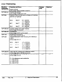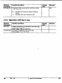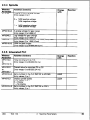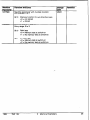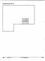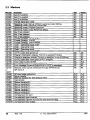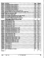
1
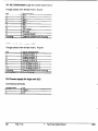
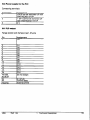
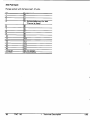
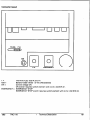
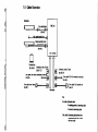
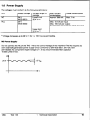
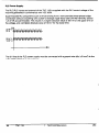
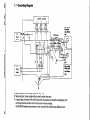
HEIDENHAIN
Technical Manual
TNC 116
Valid for NC Software
246111
Foreword
This Technical Manual has been written for the use of machine tool builders and distributors. It
contains important information on installation, electrical connection, commissioning and PLC
programming for the HEIDENHAIN TNC 116 Straight-Cut Control.
Excerpts from this manual can be used in your machine documentation. It is possible to convert
this manual from its present format (17 cm x 24 cm) to standard letter-size format (DIN A4) by
enlarging it by a factor of 1.225.
The pre-punched holes allow this manual to be bound into the current Technical Manuals (such for
TNC 407/415)
No documentation can be perfect. Documentation undergoes continual change, and will benefit
substantially from your suggestions for additions and improvements. Please assist us by
communicating your ideas to us.
DR. JOHANNES HEIDENHAIN
Dept. V-PE
Post Box 1260
W8225 Traunreut
Germany
2
TNC 116
GmbH
l/93
CONTENTS
1
1.1
1.2
1.3
1.4
1.5
1.6
1.7
1.6
Twhnkal
Dmwiption
Technical Data
Hardware
Machine Function Keys
Connector Layout
Cable Overview
Power Supply
Grounding Diagram
Dimensions
4
4
6
7
9
14
15
17
16
2
2.1
21.1
Machine Parameters
What Are Machine Parameters?
User Parameters
23
23
24
24
24
25
25
26
26
27
28
29
29
3
Input and Output of Machine Parameters
2.2
2.2.1 Input Format
2.2.2 Activating the Machine Parameter List
2.23 Changing the Input ValUeS
2.3
List of Machine Parameters
2.3.1 Encoders and Machines
2.3.2 Positioning
2.3.3 Operation with Servo Lag
2.3.4 Spindle
2.3.5 Integrated PLC
2.3.6 Disptay and Operation
3
3.1
3.2
3.3
l/93
PLC Deacrlptlon
PLC EPROM
Trace Function
Markers
TNC 116
..
1 Technical Description
35
35
37
36
3
1
Technical
1.1 Technical
Description
Data
The TNC 116 is a 3-axis straight-cut control for paraxial machining on simple boring and milling
machines using single-axis or common drives wnhout backlash.
The operating panel contains not only the LCD monitor screen but also the machine axis keys and
the electronic handwheel. If the electronic handwheel is not used, ff is also possible to use drives
with backlash.
MC 116
l
.
l
control
typs
.
.
Program memory
Tool
Operating
l
l
modes
.
input
Display step
Progmmmable
functions
Manual posftfon input at TNC operating panel
l
5pm(lOpm)
.
Nominal posnion in absolute or Incremental
dimensions
Tool radius compensation R+/RSpindle speed and feed rate selectable from tables
.
functions
One tool with compensation of tool length and radius
.
l
AddItional
Battery-buffered RAM for NC programs wkh a
maximum of 500 blocks each
l
l
l
mnge
l
4999.999 mm (196.6503 in.)
Max. traverse
sfmed
.
30mJmin (1161 ipm)
TNC 116
(
Rapid traverse
Max. tmvama
4
,
Straight-cut control for 3 axes
Paraxial positioning
Manual
Handwheel (Handwheel, Jog Positioning, Absolute
Poslioning)
Program execution (single blcck or full sequence)
Edfing
l
Progmm
Complete with
LCD monitor screen (240x200 pfxels, 114x96 mm)
Electronic handwheel (0.5 to 6 mm traverse
range/rev.)
Machine operating buttons integrated into the TNC
operating panel
1
1 Technical Description
l/93
Posltlon feedback
l
Incremental HEIDENHAIN encoders 2Opm (40pm),
preferably with distancecoded reference marks wkh
grating period 20pm
Control
l
3 encoder inputs (3 slnusoidal signal inputs)
15 PLC inputs + 1 PLC Input for EMERGENCY
STOP monitoring
Inputs
l
Control outputs
l
l
kltegmted
PLC
4 analog outputs ior axes X,Y.Z, and spindle S
15 PLC outputs + 1 PLC output for EMERGENCY
STOP
l
External programming in the form of an Instruction
list
PLC EPROM with PLC dialogs and error messages
Power supply
l
24V
Power consumption
l
7 W (without encoders)
Amblent
l
Operating temperature:
0 to + 45’C
-30 to + 7o’C
Storage temperature:
Rel. humidity, annual average: < 75%
Max. 30 daysiyear, naturally distributed: < 95%
nqulnments
l
l
Lmguages
l
German, English, French, ltalian. Spanish
Weight
l
3.3 kg
l/Q3
TNC 116
1 Technical Description
5
1.2 Hardware
TNC 116
Id.-Nr. 271 209
3
I
\
Ia
HEIDENHAIN
@
Y10,000
0,005
z+
H4Hwuo: 1 2 41 a
ZIJST. : a.w 0.w lO.ccrnPl
s scu: aso a@*“J Sal: Em 7s
6
TNC 116
1 Technical Description
l/93
1.3 Machine
Function
Keys
‘LC Rapid Traversa
lol
Cl
clsl
[Al
rl44
El
cl
NC Stop
1128
X
Spindle Stop
1129
X
NC Start
1130
Open tool holder
I131
coolant
132
Rapid traverse
1133
Axis direction X -
1134
+x
cl
Axis direction X+
1135
-Y
cl
Axis direction Y -
1136
-X
l/93
0pen.r
TNC 116
1 Technical Description
Clour
7
KW
4-Y
cl
cl
+z
L
-Z
cl5s
cl53
8
Function
‘LC Rapid Traverrs
Axis direction Y+
1137
Axis direction 2 -
1138
X
Axis direction Z+
1139
X
Spindle ON
counterclockwise
1140
Spindle ON clockwise
1141
TNC 116
1 Technical Description
Closer
l/%3
.
•l
1.4 Connector
qx3
lol
x42
Layout
Xl = Encoder 1 (-I
X2 = Encoder 2 (-)
X3 = Encoder 3 (-1
x41
x41 = PLC outputs
x42 = PLC Inputs
X21 = Not used
X8 = Nominal value out 1. 2.3. S
X44 = 24 V Power Supply for PLC
X31 = 24 V Power Suppb for NC
B = System ground
1193
TNC 116
1 Technical Description
9
Xl, X2. X3 Encodera 1.23 (sinusoidal signal input)
Flange socket with female insert, g-pole
Pin
1
1Assignment
I no,
9
Housing
v UN1
I Internal shield
1 External shield=unit housing
X8 Nominal
value output 1,2,3
Flange socket with female insert, 15pole
Pin
1
3
5
,El
9
11
13
Housing
2,7,10,12,14
X31 Power
Signal designation
Analog output 1
- Ilog output 2
Analog output 3
Analog output S
0 V analog output 1
0 v analog output 2
0 v analog output 3
External shield=unit housing
Do not assign
supply for logic unit ILEI
Connecting teminals
Assignment
1
2
10
1 Pin
(+24V
IOV
TNC 116
1 Technical Description
l/93
XU Power
supply for the PLC
x41 PLC output
Flange socket with female insert, 37-pole
Pin
1
Assignment
00
7
8
9
10
11
12
13
14
15
16 to32.
35.36.37
33
34
Housing
06
07
08
09
010
011
012
013
014
Do not assign
l/93
n v IPI rt
1Control ready
1 External shield
TNC 116
1 Technical Description
x42 PLC input
Flange socket with female insert, 37-p&
Pin
1
2
3
4
1Assignment
I In
I1
12
13 Acknowledgment
for test
‘Control is ready’
14
15
I6
17
I8
I9
Irn
5
6
7
8
9
10
11
15
16
17to37
Housing
12
114
115
Do not as+-J,cJ,,
External rshield
TNC 118
1 Technical Description
l/93
lU
FOBA
c
I
IUUU
ON
EMERGENCY
FlA
Ha
F=
x33 =
ON=
Fine-wire fuse. 0.63 A and 1A
Battery holder (three 1.5 W LR6 batteries)
Control voltage ON
ON switch requires switch element with Id.-Nr. 242 575 01.
EMERGENCY = EMERGENCY STOP
EMERGENCY STOP switch requires switch element with Id.-Nr. 242 575 02
l/93
TNC 116
1 Technical Description
13
1.5 Cable Overview
TNC 116
Cal. cabI& mm. “me
244 007
-4
dl
can. cable. PLC tmnSt*r ““2
I@
244 017
1.6 Power Supply
The~voltages must conform to the following definitions:
Unit
Supply voltage
NC
24V
NDE 0551)
24V
(VDE 0550)
PLC
Voltage range DC
average
Lower limit
20.4 V -=
Max. current
consumption
Approx. 300 mA
Power consumption
Max. 7 w
Max. 10 mA per input
Max. 100 mA per output
At most one input may be short circuited
Upper limit
3, !.I=”
1’ Voltage increases up to 36 V -= for t < 100 ms are permissible.
Do not connect the NC of the TNC 116 to the control voltage of the machine! The NC requires its
own externally-generated power supply which conforms to DIN VDE 0551.24 V DC with
permissible AC component (ripple voltage) of 1.5 Vpp (recommended filter capacitor
10 000 pFI40 V DC).
UA
24V-mL
15V,
- .
I
l/93
TNC 116
1 Technical Description
15
PLC Power Supply
The PLC (PLC inputs and outputs) of the TNC 116 is supplied with the 24 V control voltage of the
machine generated in conformance with VDE 0550.
Superimposed AC components such as those arising from a not-controlled three-phase bridge
connection without smoothing with a peak-twverage
ripple factor (see DIN 401 lOt1075. section
1.2) of 5% are permissible. This results in a largest absolute value of 33.4 V for the upper limit of
the voltage, and a smallest absolute value of 18.5 V for the lower limit.
20.4 V
16.5V
The 0 V line of the PLC power supply must be connected with a ground wire (dia. 2 6 mm?) to the
main system ground of the machine.
16
TNC 116
1 Technical Description
l/93
1.7 Grounding
Diagram
1) Measuring point: noise voltage against housing = OV
‘21 Measuring point: noise voltage with grounded nominal value input
31 A ground loop will result if the nominal value input is grounded, so the cable configuration of OV
and the ground line should be short and ensure a low noise voltage.
HEIDENHAIN therefore recommends a motor controller with nominal value difference inout.
1.8 Dimensions
16
TNC 116
1 Technical Description
l/93
9
l/93
TNC 116
1 Technical Description
19
22
TNC 116
1 Technical Description
lt93
2 Machine
Parameters
2.1 What Are Machine
Parameters?
The TNC requires access to specific data such as the traverse range and accelerations so that the
programmed instructions can be executed correctly on the machine.
Machine parameters enable the machine builder to define these data. Machine parameters also
allow activation of certain functions for HEIDENHAIN TNC - such as automatic gear changing or
manualiychanged spindle speed stages -which
are required only on certain machine types.
The machine parameter list groups the parameters according to function. These groups deal with
the following subjects:
Meebine
olOOO17003000 4000 7200 7400 7800 -
Paramatws
999
1399
1999
3999
4999
7399
7599
7699
Subject
Encoders and machines
Positionihg
Operation with servo lag
Spindle
Integrated PLC
Display and programming
Machining and program execution
Hardware
When there are several possible input values for a function (such as a separate value for each axisl,
the machine parameter has an additional index number.
Example:
MP 120: Assignment
MP 120.0
MP 120.1
MP 120.2
of the analog outputs
Analog output for X axis
Analog output for Y axis
Analog output for Z axis
‘--
Entry values with single-axis drives:
MP 120.0 = 0
MP 120.1 = 1
MP 120.2 = 2
Entn/ values with common drive on axes X and Z. single drive on axis Y:
MP 120.0 = 0
MP 120.1 = 1
MP 120.2 = 0
l/93
TNC 116
2 Machine Parameters
23
2.1.1 User Parameters
The MOO function ‘User Parameters’
allows direct access to certain machine parameters.
2.2 Input and Output of Machine Parameters
If no machine parameters have yet been entered in the TNC (such as before the first
commissioning). the TNC displays the list of machine parameters after performing the memory
test. The machine parameter values must then be entered manually at the operating panel.
Confirm each value you key in by pressing the ‘ENF key.
2.2.1 Input Format
A number is entered for each machine parameter. These numbers can be values such as the
acceleration in mm/s or the analog voltage in V.
Some machine parameters have multiple functions. For these machine parameters, the input value
has to be calculated depending on the functions to be activated.
Bits 0 to 15 allow up to 16 different functions to be activated by a single machine parameter. The
input value is calculated by adding the decimal values of the corresponding bits for the desired
functions.
Bit
0
1
2
3
4
5
6
7
9
9
10
11
12
13
14
15
24
Decimal Value
1
2
4
B
16
32
64
126
256
512
1024
2046
4096
8192
16364
32766
TNC 116
2
Machine Parameters
l/93
Example:
MP 210: Counting direction of the encoder signals
Bit 0
Axis X
Bit 1
Axis Y
Bit 2
Axis 2
+0
+l
+0
+1
+0
+l
=
=
=
=
=
=
positive
negative
positive
negative
positive
negative
You want axis X to count positive, axes Y and 2 negative.
The input value for MP 210 is therefore: 0+2+4 = 6
2.2.2 Activating
the Machine Parameter List
After entering the values for the machine parameters, You can leave the machine parameter list bY
pressing ‘Manual’. The control recognizes incorrect entries, which You can then correct.
If no errors are recognized by the control, the machine parameter editor is automatically closed and
the control goes into operation.
2.2.3 Changing the Input Values
The machine parameter editor can be called up with the MOD function ‘Code Number’.
Access to the complete list of machine parameters is only possible bY entering cede number
95149.
Only some of the machine parameters can be accessed with the MOD function ‘User Parameters’.
User parameters are machine parameters which can be changed by the machine operator (see the
TNC 116 User’s Manual). User parameters are identified in’frre following list with USER.
To leave the machine parameter editor, press the ‘Manual’ key.
l/93
TNC 116
2 Machine Parameters
25
2.3 List of Machine
2.3.1
Encoders
Machin.
Parameter
MPllO.O-2
MP120.02
Parameters
and Machines
Function and Input
:hanga
with
&ssignment of encoders to inputs
Entry range: 0 to 2
D = Encoder
1 = Encoder
2 = Encoder
Assignment
Entry range:
input Xl
input X2
input X3
of the analog outputs
0 to 2
Reaction
RESET
t
RESET
0 = output 1
1 = output 2
2 = output 3
MP210
MP330.02
With a common drive the corresponding axes are
assigned the same output.
Counting direction of the encoder signals
Entry range: 0 to 7
Bit 0
Axis X
Bit 1
Axis Y
Bit 2
Axis 2
+0
+l
+0
+2
+0
+4
=
=
=
=
=
=
I
RESET
positive
negative
positive
negative
positive
negative
Grating period
Entry values: 20 or 40
RESET
20 = Grating period 20 urn
Display step 5 urn
40 = Grating period 40 urn
Display step 10 urn
MP730
Non-linear axis error compensation
Entry range: 0 to 7
Bit 0
MP910.02
MP920.62
+0 = not active
+l = active
Bit 1
Axis Y
+0 = not active
+2 = active
Bit 2
Axis 2
+0 = not active
+4 = active
Positive software limit switch
Entry range:
-99999.9999 to +99999.9999 [mm1 or IO1
Negative software limit switch
Entry range:
-4999.9999
26
Axis X
TNC 116
to +4 999.9999 lmml
2
Machine Parameters
l/93
2.3.2 Positioning
hangr
rith
MP1040
Entry ran&e: 0.005 to 2 [mm1
Polarin, of the nominal value voltage with positive
direction of traverse
Entry range: 0 to 7
+0 = positive
+l = negative
+0 = positive
Bit 1
Axis Y
+2 = negative
+0 = positive
Bit 2
Axis 2
+4 = negative
Analog voltage with rapid traverse
Entry range: 4.5 to 9 IV1
Acceleration
Entry range: 0.001 to 3.0 [m/s~l
Movement monitoring
Entry range: 0.03 to 10 IV1
Traverse direction when crossing the reference
marks
Entry range: 0 to 7
Bit 0
MP1050.&2
MP1060.0-2
MP1140
MP1320
MP1330.0:
MP1340.0-:
Axis X
Bit 0
Axis X:
Bit 1
Axis Y:
Bit 2
Axis 2:
+0
+ 1
+0
+2
+0
+4
I
=
=
=
=
=
positive
negative
positive
negative
positive
negative
Feed rate for crossing the reference marks
Entry range: 60 to 30 000 Imm/minl
Axis sequeyce when crossing the reference mark!
Entry range: 0 to 3
0
1
2
3
143
Iemtion
USER
FIEF
= No reference mark evaluation
= Axis X first
= Axis Y first
= Axis Z first
TNC 116
2 Machine Parameters
27
Machine
Par*metbr
MP1350.0-2
Function and Entry
Procedure when crossing the reference marks
Entry values: 0 or 1
0=
1=
MP1610.02
28
Reaction
REF
Encoder with distance-coded reference
marks
Encoder with one reference mark
2.3.3 Operation
?&chin*
Parrmater
MPl720.
Chahge
with
,
with Servo Lag
1 Function and Entry
I Chmgo
I Reaction
Position monitoring for operation with servo lag
Kv factor for operation with servo lag
TNC 116
2 Machine Parameters
l/93
2.3.4 Spindle
0 = MO3 positive voltage
MO4 negative voltage
1 = MO3 negative voltage
MO4 positive voltage
or gear ranges
2.3.5 Integrated
PLC
Machine
Pk3I~llWt~~
MP4110.0
to
MP4110.15
MP4120.0
to
MP4120.7
MP4310.~?-2
MP4310.3
MP4310.4-9
143
Pm-set value for counters CO to C31
Entry range: 0 to 65 535 124 ms]
Set a number in the PLC (M2192 to M2194)
Entry values: 0 or 1
Display spindle speed
Entry values: 0 or 1
0 = Display
1 = No display
Set a number in the PLC (M2196 to 2201)
Entry values: 0 or 1
TNC 116
2 Machine Parameters
USER
USER
2s
2.3.6 Display and Operation
Machine
Parameter
MP7210
MP7230
MP7265
MP7320
MP7321
MP7322
MP7323
Function and Entry
Change
with
USER
Programming station
Entry values: 0. 1. 2
3 = Control and program
1 = Programming station ‘PLC active’
2 = Programming station ‘PLC not active’
Dialog language
Entry range: 0 to 4
D = German
1 = English
2 = French
3 = Italian
4 = Spanish
Taking tool length into account in the position
display of the tool axis
Entry values: 0 or 1
0 = Tool length ignored
1 = Tool length taken into account
Screen contrast for LCD monitor
Entry range: 0 to 15
0 = Lowest contrast
15 = Highest contrast
Unit of measurement: mm or inch
Entry values: 0 or 1
O=mm
1 = inch
Switchover of position display
Entry range: 0 to 2
Reaction
RESET
USER
USER
USER
USER
USER
0 = Actual position (ACTL)
1 = Servo lag (LAG)
2 = Reference position (REF)
Enable ‘Program run full sequence’
Entry values: 0 or 1
0 = No ‘Program run full sequence’
1 = ‘Program run full sequence’
(Hold down ‘Program Run’ key and press ‘NC
Start’ key)
30
TNC 116
2 Machine Parameters
l/93
Machhle
Parametr
MP76BO
Function and Entry
1 Machine parameter with multiple function
Entry values: 0 or 1
Bit 0
MP7690
Change’
with
USER
Reaction
Memory function for axis direction keys
+0 = not stored
+l = stored
Memory test at switch-on
Entry range: 0 to 3
Bit 0
RAM test
+0 = Memory test at switch-on
+l = No memory test at switch-on
Bit 1 EPROM test
+0 = Memory test at switch-on
+2 = No memory test at switch-on
l/93
TNC 116
2 Machine Parameters
31
32
TNC 116
2 Machine Parameters
l/63
j
++
,....
j**\
/
t”““,
. . . . ..i
i
1
(....-,
f......,
j
i
/
34
TNC 116
2 Machine Parameters
1/93
3 PLC Description
3.1 PLC EPROM
The PLC EPROM is a 1 MB chip with 16bit data width.
The EPROM is programmed externally either on another TNC control (such as the TNC 360) or at a
PC. It is programmed in Motorola format-that
is, the MSB of a word is at the first flower
significance) address.
$0000
‘LC Program
SF000
lrror Messages
$FF66
SFFFE
$FFFF
‘LC Software Number
:hecksum
)ne’a complement checksum
and Dialogs
The error messages and dialogs are stored in the following sequence and syntax t’...‘,O) in the
different languages. Up to 30 characters can be stored in each dialog.
German ’ .............................. ‘,O
English ’ .............................. ‘,O
French ’ .............................. ‘.O
Italian ’ .............................. ‘.O
Spanish ’ .............................. ‘.O
l/63
TNC 116
3
PLC Description
35
Expansion
slots, TNC 116
I
36
TNC 116
3
PLC Description
l/93
3.2 Trace Function
Code number 807 667 accesses
the tables for inputs, outputs, markers, counters and timers.
To activate the trace function, press the ‘I’ key. Then press the ‘R-’ key to select the tables.
Use WI’ to page up within the list of PLC markers, and ‘R+’ to page down.
To leave the trace function, press ‘NOENT’.
l/93
TNC 116
3
PLC Description
37
3.3 Markers
n
set
Raaet
NC
NC
NC
NC
NC
NC
NC
NC
0”
5 Yin position
-.
.3n
‘ar code
,-...,-
“.
0”
le: Cross Reference Marks
ressed
:sed
sed
1st bit iL.W
3
1
NC
NC
I.NC
NC
I
mode
mode
mode fMSt7I
I
I
/
\
MP4310.9
.-
rse Xaverse Y+
‘erseYie Z+
,e 7‘t
I Complement memory function for axis direction keys
M24670 1Complement telad enable
M2466
3 PLC Description
,
.
-
1 NC
1PLC
I
I
I
I
I function for axis direction keys
enable
LaYL
TNC 116
1k
I
evaluation)
38
,
NC
NC
NC
NC
NC
nd bit
I 3rd bit (MSL3)
,
to
M770
..-
PLC
PLC
PLC
PLC
PI P
PLC
PLC
PLC
PLC
PLC
PLC
PLC
PLC
PLC
I
I
PLC
PLC
PLC
PLC
PI rPLC
PLC
PLC
PLC
PLC
PLC
PLC
PLC
PLC
l/93
14 traverse X+
terse xual traverse Y+
r?.e Y,erse z+
traverse z.-
set
Rret
PLC
PLC
PLC
PLC
PLC
PLC
PLC
PLC
PLC
PLC
PLC
PLC
change if set
,
I MO4
&-
1 PLC
or gear change)
!ar change)
. ^,^.
X+ axis
X-axis
:ioningY+ axis
Y-axis
Z+ axis
wsltloning Z-axis
I loop X axis
pY axis
transfer, X axis
r. Y axis
lsfer. Z axis
in for X axis
sition for Y axis
1Heterence ena position for Z axis
M2624 1Limit swi‘tch x+
M?Wri
. - -- -i I, I-.imit . switch
-. .-. X-.
: switch Y+
Error messagesand dialogs
l/93
TNC 116
&.,
I PLC
1 PLCT PLC
1PLC 1 PLC
-. _
-. _
IJLC
Ml500 to Ml659
tn L”IT(EO
lsitioning
X+ axis
X-axis
Y+ axis
Y-axis
+ axis
-axis
,
PLC
PLC
PLC
PLC
PLC
PLC
PI c
1 PLC
1 PLC
PLC
PLC
PLC
PLC
PLC
PLC
PI r
PLC
PLC
PLC
PLC
PLC
PLC
.._
1 NC
I ..NC
1NC
FLC
I I
PLC
PLC
PLC
PLC
PLC
PLC
PI r?
1PLC
1PLC
PLC
PLC
PLC
PLC
PLC
PLC
PI r
PLC
PLC
PLC
PLC
PLC
PLC
* ..1 NC
1 ..NC
1 NC
PLC
3 PLC Description
39
.-
-
_-
HEIDENHAIN