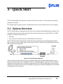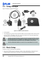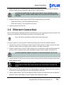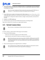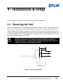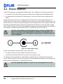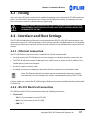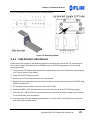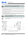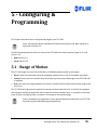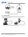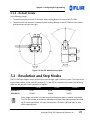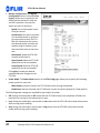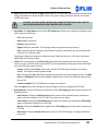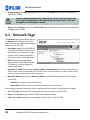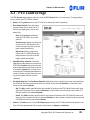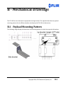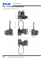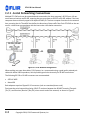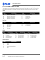
1
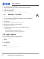
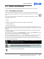
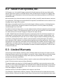
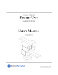
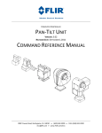
High‐Performance
Pan‐Tilt Unit
MODEL: PTU‐E46
VERSION: 1.00
REVISION DATE: September, 2014
User Manual
PTU‐E46 User Manual
DOCUMENTCONTROL
Date
09/2014
Author
A. Hernandez
Rev. #
1.00
Changes
Initial release
COPYRIGHTNOTICE
PTU‐E46 User’s Manual, version 1.00 (09/2014)
©2014 by FLIR Systems, Inc., 70 Castilian Drive, Goleta, CA 93117, (805)964‐9797, FAX: (805)690‐5933
www.FLIR.com/MCS
All rights reserved. Protected under numerous U.S. patents, including 5463432 and 5802412 with other
patents pending. No part of this book may be reproduced, stored in a retrieval system, or transcribed in
any form or by any means including but not limited to electronic, mechanical, photocopying, recording,
or otherwise, without the prior written permission of FLIR Systems, Inc.
The information in this manual is subject to change without notice and, except for the warranty, does
not represent a commitment on the part of FLIR Systems, Inc. FLIR Systems, Inc. cannot be held liable for
any mistakes in this manual and reserves the right to make changes.
Copyright 2014, FLIR Commercial Systems, Inc.
Table of Contents
1 ‐ Introduction ................................................................................................................................. 1
1.1 ‐ General PTU‐E46 Features ................................................................................................................ 1
1.2 ‐ E Series Features ........................................................................................................................... 2
1.3 ‐ Applications ....................................................................................................................................... 2
1.4 ‐ About This Manual ............................................................................................................................ 3
1.4.1 ‐ Formatting Conventions ........................................................................................................... 3
1.5 ‐ Models ............................................................................................................................................... 4
1.6 ‐ PTU‐E46 Package Contents ............................................................................................................... 4
1.7 ‐ Related Documentation .................................................................................................................... 5
1.8 ‐ Additional Resources ......................................................................................................................... 5
1.9 ‐ Technical Support .............................................................................................................................. 5
2 ‐ Safety ........................................................................................................................................... 7
2.1 ‐ Overview ........................................................................................................................................... 7
2.2 ‐ Safety Warnings and Cautions ........................................................................................................... 7
3 ‐ Quick Start ................................................................................................................................... 9
3.1 ‐ System Overview ............................................................................................................................... 9
3.2 ‐ Setup Example ................................................................................................................................. 10
3.3 ‐ Basic Setup ...................................................................................................................................... 10
3.4 ‐ Ethernet Connection ....................................................................................................................... 11
3.5 ‐ Serial Connection ............................................................................................................................ 12
4 ‐ Installation & Setup .....................................................................................................................15
4.1 ‐ Mounting the Unit ........................................................................................................................... 15
4.2 ‐ Power Sources ................................................................................................................................. 16
4.3 ‐ Fusing .............................................................................................................................................. 17
4.4 ‐ Interface and Host Settings ............................................................................................................. 17
4.4.1 ‐ Ethernet Connection .............................................................................................................. 17
4.4.2 ‐ RS‐232 Electrical Connection .................................................................................................. 17
4.4.3 ‐ RS‐485 Electrical Connection .................................................................................................. 18
4.5 ‐ Initial Power‐Up and Test ................................................................................................................ 19
4.5.1 ‐ Web Interface ......................................................................................................................... 19
4.5.2 ‐ Terminal Interface .................................................................................................................. 19
4.6 ‐ Payload Mounting ........................................................................................................................... 20
4.6.1 ‐ Side Bracket Attachment ........................................................................................................ 21
4.6.2 ‐ Payload Attachment ............................................................................................................... 23
Copyright 2014, FLIR Commercial Systems, Inc.
iii
PTU‐E46 User Manual
5 ‐ Configuring & Programming ....................................................................................................... 25
5.1 ‐ Range of Motion .............................................................................................................................. 25
5.1.1 ‐ Nodal Rotation ....................................................................................................................... 26
5.1.2 ‐ Default Limits ......................................................................................................................... 27
5.2 ‐ Resolution and Step Modes ............................................................................................................ 27
5.3 ‐ User‐Programmable Settings .......................................................................................................... 28
5.3.1 ‐ High‐Speed Operation ............................................................................................................ 28
5.3.2 ‐ Heavy‐Payload Operation ....................................................................................................... 29
5.3.3 ‐ Battery Powered Operation ................................................................................................... 30
6 ‐ Web Interface ............................................................................................................................. 31
6.1 ‐ PTU Configuration Page .................................................................................................................. 31
6.2 ‐ Network Page .................................................................................................................................. 34
6.3 ‐ PTU Control Page ............................................................................................................................. 35
A ‐ Electrical Specifications .............................................................................................................A‐1
B ‐ Mechanical Drawings ................................................................................................................ B‐1
2.1 ‐ Payload Mounting Pattern .............................................................................................................B‐1
2.2 ‐ PTU‐E46 Dimensions ......................................................................................................................B‐2
2.3 ‐ PTU‐E46 Controller Dimensions .....................................................................................................B‐3
C ‐ Networking ............................................................................................................................... C‐1
3.1 ‐ Ethernet ..........................................................................................................................................C‐1
3.2 ‐ Serial ...............................................................................................................................................C‐1
3.2.1 ‐ Serial Networking Connections .............................................................................................C‐2
3.2.2 ‐ ASCII Command Syntax .........................................................................................................C‐3
3.2.3 ‐ Serial Command List ..............................................................................................................C‐4
D ‐ Troubleshooting ........................................................................................................................D‐1
4.1 ‐ Mechanical .....................................................................................................................................D‐1
4.2 ‐ Networking .....................................................................................................................................D‐1
4.3 ‐ Technical Support ...........................................................................................................................D‐2
E ‐ Regulatory & Warranty Information .......................................................................................... E‐1
5.1 ‐ Regulatory Information .................................................................................................................. E‐1
5.2 ‐ About FLIR Systems, Inc. ................................................................................................................ E‐2
5.3 ‐ Limited Warranty ........................................................................................................................... E‐2
iv
Copyright 2014, FLIR Commercial Systems, Inc.
1‐Introduction
The PTU‐E46 Pan‐Tilt Unit (PTU‐E46) from FLIR Systems, Inc. provides low‐cost, fast, and accurate posi‐
tioning of cameras and other payloads. This User Manual contains setup, general configuration, wiring, and mechanical interface information that is intended for use by design engineers and integrators who are configuring, installing, and programming the PTU‐E46. Please see “Related Documentation” on page 5 for a list of other documents related to the PTU‐E46.
Note: This manual describes setting up and using the PTU‐E46 unit. Optional modules are not included in these instructions. If your PTU‐E46 includes any optional modules, please refer to the documentation included with those modules for help with their setup and use.
1.1‐GeneralPTU‐E46Features
The PTU‐E46 series offers the following general features:
•
Small form factor
•
Serial communication capability via terminal or computer
•
PTU‐E46‐17 performance highlights include:
•
‐
Payload capacity: 6lbs
‐
Speed: over 300° per second
‐
Resolution: 0.129° PTU‐E46‐70 performance highlights include:
‐
Payload capacity: 9lbs ‐
Speed: over 60° per second
‐
Resolution: 0.0032°
•
Precise position, speed, and acceleration control
•
On‐the‐fly position and speed changes
•
Self‐calibration on reset with reduced motion
•
Host‐controllable power consumption
•
Simple ASCII command mode
Copyright 2014, FLIR Commercial Systems, Inc.
1
PTU‐E46 User Manual
•
High‐speed binary command interface
•
Constant‐current DMOS motor drives for increased performance and control
•
Unregulated 12‐30 VDC power input
•
Flexible connectivity options
Please refer to the PTU‐E46 Product Datasheet for complete specifications.
1.2‐ ESeriesFeatures
The PTU‐E46 includes the following new features:
•
Built‐in Ethernet/Web IP interface for easy configuration, control, and diagnostics
•
Built‐in geo‐pointing (GPM) support
•
Pelco‐D support
•
Compatible with the PTU‐SDK software development kit
•
Higher command rates with lower latency and jitter
•
Reduced calibration movement
•
Full backward compatibility with previous PTU‐D46 models that includes:
‐
Mounting pattern
‐
ASCII and binary application command interface
‐
Overlapped capabilities with previous PTU‐D46 models.
1.3‐Applications
The PTU‐E46 is well suited for the following applications:
•
Robotics & computer vision
•
Webcam
•
Security camera control
•
Teleconferencing
•
Advanced monitoring systems
•
tracking
•
Photography, videography, and special effects
2
Copyright 2014, FLIR Commercial Systems, Inc.
E
Chapter 1: Introduction
1.4‐AboutThisManual
This section describes the formatting conventions and information contained in this manual.
1.4.1‐FormattingConventions
This manual uses several formatting conventions to present information of special importance.
Commands and other information that is new for the E Series PTUs include the “E” icon shown here.
E
Lists of items, points to consider, or procedures that do not need to be performed in a specific order appear in bullet format:
•
Item 1
•
Item 2
Procedures that must be followed in a specific order appear in numbered steps:
1. Perform this step first.
2. Perform this step second.
Specific keyboard keys are depicted in square brackets and are capitalized, for example: [ESC]. If more than one key should be pressed simultaneously, the notation will appear as [KEY1]+[KEY 2], for example [ALT]+[F4].
Interface elements such as document titles, fields, windows, tabs, buttons, commands, options, and icons appear in bold text.
Menus and submenus have the notation Menu>Submenu. For example, “Select File>Save” means that you should first open the File menu, and then select the Save option.
Specific commands appear in standard Courier font. Sequences of commands appear in the order in which you should execute them and include horizontal or vertical spaces between commands.
This manual also contains important safety information and instructions in specially formatted callouts with accompanying graphic symbols:
WARNING: CAUTIONS ALERT YOU TO THE POSSIBILITY OF PERSONAL INJURY IF THESE INSTRUCTIONS ARE NOT FOLLOWED.
CAUTION: CAUTIONS ALERT YOU TO THE POSSIBILITY OF EQUIPMENT OR PROPERTY DAMAGE IF THESE INSTRUCTIONS ARE NOT FOLLOWED.
Note: Notes provide helpful information.
Copyright 2014, FLIR Commercial Systems, Inc.
3
PTU‐E46 User Manual
1.5‐Models
Each PTU‐E46 unit includes a model number that is located on the base of the unit. This number lists the options present on that particular unit. Different options may require specialized instructions, and this manual will refer to this section where necessary to ensure that you are following the appropriate direc‐
tions.
The PTU‐E46 model number appears as follows:
Figure 1‐1: PTU‐E46 Part Numbering
1.6‐PTU‐E46PackageContents
Your PTU‐E46 package includes the fol‐
lowing items:
•
PTU‐E46 pan‐tilt unit (1) with external controller (PTU‐E46) (2)
•
7ft cable (PT‐CABLE‐CE or PT‐CABLE‐
CE‐W) (3)
•
RS232 cable (4)
•
User Manual (NS)
•
Command Reference Manual (NS)
•
CD containing the PTU Finder utility (NS)
•
(Optional) AC/DC power supply (PT‐
PS‐INT30V‐NA or –EC) (5)
Figure 1‐2: PTU‐E46 components
4
Copyright 2014, FLIR Commercial Systems, Inc.
Chapter 1: Introduction
•
(Optional) USB to RS485 adapter cable (PTU‐CONV‐USB‐RS485) (6)
•
(Optional) Alternate length controller cables (not shown)
•
(Optional) Software Development Kit (PTU‐SDK) (not shown)
•
(Optional) Side bracket (D46‐BKT‐ZSTD) (7)
1.7‐RelatedDocumentation
The following additional documentation is available for your PTU‐E46 unit:
•
PTU‐E46 Configuration Guide: options and accessories ordering guide
•
PTU‐E46 Product Datasheet: product specifications
•
Pan‐Tilt E Series Command Reference Manual: command instructions
1.8‐AdditionalResources
FLIR Systems, Inc. also maintains a technical support Web site with additional resources for customers in the Support section at www.FLIR.com/MCS. Resources include electronic copies of user manuals, firm‐
ware downloads, 3D CAD models, technical notes, and other information.
1.9‐TechnicalSupport
FLIR Systems, Inc. provides a range of technical support options:
•
Email: SBA‐[email protected]
•
Web: www.FLIR.com/MCS
•
Phone: (888)747‐3547
The preferred method of contacting Technical Support is via email, which helps ensure proper dispatch‐
ing and tracking to address your questions promptly.
When contacting Technical Support, please provide the following information:
•
PTU model and configuration
•
Payload (Please include photos, if possible.)
•
Parameter settings
•
Description of issue/symptoms
Copyright 2014, FLIR Commercial Systems, Inc.
5
PTU‐E46 User Manual
This page intentionally left blank.
6
Copyright 2014, FLIR Commercial Systems, Inc.
2‐Safety
2.1‐Overview
This chapter contains important safety instructions. You must read, understand, and comply with all of these safety instructions in order to protect both persons and property. The benefits of a safe installa‐
tion include increased usability, reliability, and reduced damage to the PTU, payload, and/or other prop‐
erty.
2.2‐SafetyWarningsandCautions
•
PTU‐E46 installation and setup should be only be performed by qualified personnel.
•
The installation must comply with all applicable codes (such as building codes, marine safety codes, etc.).
•
The installation must be free of obstructions throughout the entire range of pan‐tilt motion. When planning the installation, make sure to take the payload into account to ensure that the PTU‐E46 and payload remain unobstructed at all times.
•
All mounting methods and materials must be capable of supporting at least four times the combined weight of the PTU‐E46, mounted payloads, and cabling.
•
Corrosion‐resistant hardware (such as stainless steel screws) must be used for all outdoor installa‐
tions. •
Do not install the PTU‐E46 in any location that exceeds the PTU‐E46’s environmental specifications.
•
Always incorporate a readily accessible power disconnect into the installation wiring. (See Sections 3.4 and 3.5.)
•
Removing power by disconnecting the power cable or cable harness is not recommended and can result in damage to the system.
•
All service procedures must be performed by qualified service personnel in accordance with all appli‐
cable instructions.
•
If the PTU‐E46 is damaged, immediately remove power and contact FLIR Systems, Inc.
•
Only use replacement parts recommended by FLIR Systems, Inc.
•
Use caution when lifting the PTU‐E46 and/or payload.
Copyright 2014, FLIR Commercial Systems, Inc.
7
PTU‐E46 User Manual
•
Keep all persons and objects well away from the PTU‐E46’s panning and tilting radius with payload installed.
•
Do not touch or otherwise handle the PTU‐E46 while in motion or if there is a possibility of motion. Always remove power before servicing the PTU‐E46 and/or payload.
8
Copyright 2014, FLIR Commercial Systems, Inc.
3‐QuickStart
The PTU‐E46 provides direct Ethernet and serial control for all motions. You may also use a joystick or proprietary controller.
This chapter helps you power up your PTU‐E46 and test direct communications from a host computer.
3.1‐SystemOverview
The PTU‐E46 includes an integrated controller that can be accessed using a Web/Ethernet interface. The controller will also accept control commands from any host computer over a serial (RS‐232 or RS‐485) connection. The basic connections are:
•
DC power
•
Pan‐tilt control via either Ethernet or RS232/485 serial connection
The PTU‐E46 also allows payload pass‐through wiring that internally routes payload signals (payload power, video, etc.) from a single stationary connector in the PTU‐E46 base to a single payload connector that moves with your payload.
Figure 3‐1: Pan‐Tilt System Overview
You may control the PTU‐E46 from any host computer using either the built‐in Web interface or the ASCII protocol described in the included Series Pan‐Tilt Command Reference Manual. The PTU‐E46 also supports a binary protocol via a C Software Development Kit (PTU‐SDK) for high speed, hard real‐time controls such as tracking. Drivers are also available using third‐party software packages such as LabVIEW and digital video control systems.
Copyright 2014, FLIR Commercial Systems, Inc.
9
PTU‐E46 User Manual
3.2‐SetupExample
Figure 3‐2 displays a typical PTU‐E46 setup:
Figure 3‐2: Sample PTU‐E46 installation
•
In this example:
•
The PTU‐E46 unit (1) connects via the controller cable (2) to the PTU‐E46 controller, which uses the optional RS‐485 to USB adapter cable (4) to connect to the host PC (5). The power supply (6) pro‐
vides DC power to the PTU‐E46 unit and controller. CAUTION: ONLY MOVE THE PAN‐TILT AXES USING THE KNOBS MOUNTED ON THE PTU MOTORS WHILE THE UNIT IS POWERED OFF. MANUAL ROTATION OF PAN‐TILT AXES (CALLED BACKDRIVING) CAN DEGRADE UNIT PERFORMANCE AND ACCURACY.
CAUTION: REMOVING POWER BY PULLING THE PLUG CAN DAMAGE THE PTU‐E46.
3.3‐BasicSetup
To perform a basic PTU‐E46 setup and installation:
1. Mount the PTU‐E46 securely to a lab bench, tripod, or other stable platform. Verify that there is enough clearance around the unit. See Section 4.1 for detailed mounting instructions.
10
Copyright 2014, FLIR Commercial Systems, Inc.
Chapter 3: Quick Start
2. Attach one end of the included controller cable to the connector at the base of the PTU‐E46 unit, and then attach the other end of the cable to the PTU‐E46 controller.
CAUTION: DISCONNECTING THE CABLE WHILE THE PTU‐E46 IS POWERED ON CAN DAMAGE THE UNIT. ALWAYS POWER DOWN THE PTU‐E46 BEFORE DISCONNECTING THE CABLE.
3. Establish Ethernet or serial wiring to the PTU‐E46 as appropriate for your needs.
‐
Please see Section 3.4 for Ethernet/Web instructions.
‐
Please see Section 3.5 for serial/ASCII instructions.
4. Power on and test the PTU‐E46.
3.4‐EthernetConnection
The PTU‐E46 contains a Web‐based interface that allows you to test and program various functions. This interface is accessible via the Ethernet connection on the breakout cable.
Note: You may use simultaneous Ethernet and serial connections.
To connect, power on, and test the PTU‐E46 using the Ethernet connection and Web interface:
1. Connect one end of an RJ‐45 Ethernet cable to the PTU‐E46 controller, and then connect the other end of the cable to the host computer, either directly or through a router/hub.
2. Connect a power source to the PTU‐E46, making sure to incorporate a readily accessible power dis‐
connect (such as a power strip) to allow safe power removal from the system. See Section 4.3.
CAUTION: REMOVING POWER BY PULLING THE PLUG CAN DAMAGE THE PTU‐E46.
3. Ensure that the PTU‐E46 is clear to move in both axes (pan and tilt) without hitting any obstructions before applying power.
WARNING: HITTING AN OBSTACLE WHILE THE PTU‐E46 IS IN MOTION COULD CAUSE A MOUNTING OR OTHER STRUCTURAL FAILURE THAT COULD RESULT IN INJURY OR DEATH.
4. Power on the PTU‐E46. By default, the PTU‐E46 will begin a calibration sequence that will cause it to move from its current position to the center (0) positions in both axes.
5. Launch a Web browser. The PTU‐E46 supports modern versions of the Microsoft Internet Explorer®, Mozilla® Firefox®, and Google® Chrome® browsers with JavaScript enabled.
Copyright 2014, FLIR Commercial Systems, Inc.
11
PTU‐E46 User Manual
6. Run the PTU Finder utility from the CD included with your PTU‐E46 package. A list of the individual PTU‐E46 units currently connected to the network and their corresponding IP addresses will appear in the application window.
Note: If you have simultaneous Ethernet and serial connections to a PTU‐E46 unit, you may enter NI in the terminal to retrieve the IP address of the PTU‐E46 unit.
7. In your Web browser, navigate to the appropriate IP address (such as http://192.168.1.101). A Web page appears when you are connected to the selected PTU‐E46 unit. The PTU‐E46 Web inter‐
face allows you to configure the network interface, configure various parameters, and control the PTU‐E46.
8. Navigate to the PTU Control page.
9. Click the arrows to pan and tilt the PTU‐E46 and verify that it is working properly.
Please refer to Section 6 for instructions on using the Web interface.
3.5‐SerialConnection
Note: You may use simultaneous Ethernet and serial connections.
To connect, power on, and test the PTU‐E46 using the serial interface:
1. Connect the PTU‐E46 as follows:
‐
Attach one end of the RS‐232 cable to the PTU‐E46 controller.
‐
Attach the other end of the RS‐232 cable to a serial port on the host PC.
Note: Alternatively, you may connect one end of an RS‐485 to USB converter to the PTU‐
E46 controller and the other end to a USB port on the host computer. Driver installation should be automatic; if not, you may download a driver from http://www.ftdichip.com/
Drivers/VCP.htm.
2. Open a terminal program such as HyperTerminal® or TeraTerm®.
Note: HyperTerminal is available with Microsoft® Windows XP® and previous versions. You may download TeraTerm from http://ttssh2.sourceforge.jp/.
12
Copyright 2014, FLIR Commercial Systems, Inc.
Chapter 3: Quick Start
3. Create a new connection with the following communications parameters:
‐
9600 baud
‐
8 data bits
‐
1 stop bit
‐
no parity
‐
no handshaking
4. Provide DC power to the PTU‐E46. You may use the factory AC/DC power supply (PT‐PS‐INT30V‐NA or –EC). Alternatively, you may provide your own DC power source if appropriate, as described in Section 4.3.
CAUTION: USE AN APPROPRIATELY RATED POWER STRIP WITH SURGE PROTECTION TO ALLOW SAFE POWER REMOVAL WHEN YOU ARE READY TO POWER DOWN.
5. Power on the PTU‐E46 by turning on the switch on the power strip. If power is working, the unit will begin a self‐calibration and text will appear on your terminal identifying the unit’s configuration.
6. Test pan‐tilt operation by typing commands into your terminal program. The following command sequence will familiarize you with basic PTU‐E46 operation:
pp2500 *
tp-900 *
PS1900 *
pp0 *
This sequence:
‐
sets the pan axis to position 2500
‐
sets the tilt axis to position ‐900
‐
sets the pan speed to 1900 positions per second, and
‐
sets the pan position back home.
7. Power down the PTU‐E46 by turning off the switch on the power strip.
8. Mount and wire your payload (e.g. camera) on the PTU‐E46, as described in Section 4.8.
Please see Appendix C.2.2 for an overview of the ASCII command syntax and a list of commonly used commands. The Pan‐Tilt E Series Command Reference Manual contains complete command interface instructions.
Copyright 2014, FLIR Commercial Systems, Inc.
13
PTU‐E46 User Manual
This page intentionally left blank.
14
Copyright 2014, FLIR Commercial Systems, Inc.
4‐Installation&Setup
This section describes proper mechanical and electrical PTU‐E46 installation.
4.1‐MountingtheUnit
The basic mounting pattern uses two #1/4‐20 socket‐head cap screws in a 0.75” (19.05mm) side by side pattern. Both mounting screws must be used, and the mount must be strong enough to support the combined load of the PTU‐E46 unit, payload, and additional forces exerted on the system (such as wind, G forces, etc.). A good rule of thumb is that the mount must be capable of supporting at least four times the combined weight of the PTU‐E46 and payload. For example, a mount for a PTU‐E46 with a 15 lb. pay‐
load must be able to support at least 104 lbs.
WARNING: FAILURE TO USE BOTH MOUNTING SCREWS AND/OR TO SECURE THE PTU‐
E46 AND ITS PAYLOAD TO A SUFFICIENTLY STRONG MOUNTING CAN CAUSE THE INSTALLATION TO FAIL. THIS CAN RESULT IN PERSONAL INJURY OR DEATH, AND/OR DAMAGE TO THE PTU‐E46 UNIT AND/OR PAYLOAD.
1.721"
¼ ‐20
1.220"
.475"
.75"
Figure 4‐1: Hole Mounting Pattern
Copyright 2014, FLIR Commercial Systems, Inc.
15
PTU‐E46 User Manual
4.2‐PowerSources
The PTU‐E46 requires an unregulated 12‐30VDC power source capable of 17 continuous peak watts.
•
For maximum PTU‐E46 performance, use the highest motor voltage within the allowable range.
•
For the quietest and smoothest PTU‐E46 operation, you can use a lower motor voltage, such as 24VDC.
Alternative power sources that can supply at least 17W continuous can be used by attaching a 2.1/
5.5mm coaxial connector cable to a suitable DC power source (e.g., battery power, vehicle power, or an AC/DC converter). In order to achieve the highest pan‐tilt unit performance, use the highest motor volt‐
age within the allowable range. To achieve the quietest pan‐tilt operation, use a lower motor voltage (e.g., 12VDC). Operation at 12VDC limits the highest unloaded pan‐tilt speed to about 2/3 the rated max‐
imum speed (i.e., 600°/second for the PTU‐E46‐17, and 60°/second for the PTU‐E46‐70).
CAUTION: WHEN WIRING YOUR OWN POWER SOURCE, FAILURE TO COMPLY WITH WIRING AND POWER SOURCE REQUIREMENTS DESCRIBED IN THIS MANUAL CAN RESULT IN DECREASED UNIT PERFORMANCE OR DAMAGE NOT COVERED UNDER THE LIMITED WARRANTY.
Figure 4‐2: Power supply wiring
If you are providing your own DC power source, then either:
•
The power source must never supply more than 3A of current.
•
You must add a 3A fast‐blow fuse in series with your DC power source.
For example, when connecting to a vehicle battery or lighter plug, you must fuse the incoming DC source. Failure to properly fuse your input power source could cause overloading of internal protection devices, pose a safety hazard, or void product warranties.
CAUTION: REMOVING POWER BY PULLING THE PLUG CAN DAMAGE THE PTU‐E46.
16
Copyright 2014, FLIR Commercial Systems, Inc.
Chapter 4: Installation & Setup
4.3‐Fusing
If you are using a DC power source that is capable of supplying current beyond the PTU‐E46 rated maxi‐
mums, you must add an appropriate fuse in series with the DC power source. For example, you must fuse a connection made to a vehicle battery or lighter plug.
WARNING: FAILURE TO PROPERLY FUSE THE PTU‐E46 POWER SOURCE COULD OVER‐
LOAD INTERNAL PROTECTION DEVICES AND CAUSE DEATH, PERSONAL INJURY, AND/
OR DAMAGE TO THE UNIT.
4.4‐InterfaceandHostSettings
The PTU‐E46 includes both an Ethernet connection and either RS‐232 or RS‐485 communications. You may connect to your PTU‐E46 using either or both of these methods; the Web interface is only available when using an Ethernet connection, and the terminal interface is only available when using a serial con‐
nection.
4.4.1‐EthernetConnection
The PTU‐E46 Ethernet connection uses a standard Cat‐5 (RJ‐45) network cable.
•
You may connect the PTU‐E46 directly to a host computer or indirectly through a router, hub, etc.
•
The PTU‐E46 will either accept IP addresses from a DHCP server or select its own IP address if con‐
nected directly to the host computer.
•
You do not need a crossover cable.
•
If needed, you may use a coupling to extend the Ethernet connection on the breakout cable.
Note: The Ethernet and serial interfaces may be connected simultaneously; however, you should only use one interface at a time for command and control of the PTU‐E46.
Connect, power on, and test the PTU‐E46 using the Ethernet connection and Web interface as described in Section 3.4.
4.4.2‐RS‐232ElectricalConnection
PTU‐E46 units with RS‐232 communications have the following connections:
•
25‐pin serial:
‐
TxD: Pin 2 (carries data from the PTU‐E46)
‐
RxD: Pin 3 (carries data to the PTU‐E46)
‐
GND: Pin 7
Copyright 2014, FLIR Commercial Systems, Inc.
17
PTU‐E46 User Manual
•
•
‐
DTR: Pin 20
‐
DSR: Pin 6
9‐pin serial:
‐
RxD: Pin 2 (carries data to the PTU‐E46)
‐
TxD: Pin 3 (carries data from the PTU‐E46)
‐
GND: Pin 5
‐
DTR: Pin 4
‐
DSR: Pin 6
8‐pin serial (Macintosh mini‐DIN):
‐
TxD: Pin 3 (carries data from the PTU‐E46)
‐
RxD: Pin 5 (carries data to the PTU‐E46)
‐
GND: Pin 4
‐
DTR: Pin 1
‐
DSR: Pin 2:
Note: TxD and RxD assignments can vary depending on your host computer. If your ini‐
tial connection does not work, try using a null modem.
Serial communication between the PTU‐E46 and your host computer should be set as follows:
•
Baud rate: 9600. You may adjust the baud rate using software commands. Please refer to the Pan‐
Tilt E Series Command Reference Manual for instructions.
•
Start bit: 1
•
Data bits: 8
•
Stop bit: 1
•
Handshaking: off
•
XON/XOFF: not used
4.4.3‐RS‐485ElectricalConnection
PTU‐E46 units with RS‐485 communications have the following connections:
•
Duplex: full
•
Connections: Tx+, Tx‐, Rx+, and Rx‐
•
Voltage: RS‐422 or RS‐485 levels
18
Copyright 2014, FLIR Commercial Systems, Inc.
Chapter 4: Installation & Setup
Serial communication between the PTU‐E46 and your host computer should be set as follows:
•
Baud rate: 9600. You may adjust the baud rate using software commands. Please refer to the Pan‐
Tilt E Series Command Reference Manual for instructions.
•
Start bit: 1
•
Data bits: 8
•
Stop bit: 1
•
Handshaking: off
•
XON/XOFF: not used
4.5‐InitialPower‐UpandTest
This section describes how to power up and test your PTU‐E46 using either the Web or serial interface. Test and verify all cable connections and connector wiring before power‐up.
Note: Complete the initial installation and testing, then exercise the PTU‐E46 and famil‐
iarize yourself with its operations and commands before mounting your payload (such as a camera).
4.5.1‐WebInterface
To test the PTU‐E46 using the Web interface, follow the procedure in Section 3.4 to connect the PTU‐
E46, power on the unit, and access the Web interface.
The Web interface has the following pages:
•
PTU Config: Allows you to configure speed, acceleration, and power options.
•
Network: Allows you to configure the PTU‐E46 unit’s IP and MAC addresses.
•
PTU Control: Allows you to control the PTU‐E46.
Please see Section 6 for more information about the Web interface. Use the PTU Control page (see Sec‐
tion 6.3) to test PTU‐E46 motion and exercise the unit.
4.5.2‐TerminalInterface
To test the PTU‐E46 using the serial interface:
1. Configure the RS‐232 or RS‐485 port on the host computer as described in Section 3.5.
2. Power up the PTU‐E46. A boot message will appear on your terminal screen and the unit will begin a reset cycle. An asterisk (*) appears on your screen when the reset cycle is finished. If the PTU‐E46 did not reset properly, please refer to the troubleshooting instructions below.
Copyright 2014, FLIR Commercial Systems, Inc.
19
PTU‐E46 User Manual
3. Please see Appendix C.2.3 for a list of basic commands, and the Pan‐Tilt E Series Command Refer‐
ence Manual for a complete list of commands and associated parameters and other usage instruc‐
tions.
4.6‐PayloadMounting
The PTU‐E46 payload bracket system can be configured in a number of ways to support a variety of pay‐
loads including cameras, lasers, antennas, and other equipment. Figure 3 shows all bracket configura‐
tions available for the PTU‐E46.
WARNING: FAILURE TO FOLLOW ALL PAYLOAD MOUNTING INSTRUCTIONS COULD RESULT IN A STRUCTURAL FAILURE THAT MAY RESULT IN DEATH, PERSONAL INJURY, AND/OR DAMAGE TO THE UNIT.
The following guidelines apply to all payload mounts:
•
The maximum payload mounting screw size is ¼”.
•
Always use washers, lock washers, etc. as appropriate.
•
If the PTU‐E46 is being mounted in an outdoor location, use corrosion‐resistant hardware (such as stainless steel).
•
Apply thread locking compound to all screws, such as Loctite® 242, which is suitable for applications that are field serviceable since it is easily removable with common hand tools and works with both stainless and plated metals. Consider other compounds for high‐shock/vibration applications where field service is not a concern.
20
Copyright 2014, FLIR Commercial Systems, Inc.
Chapter 4: Installation & Setup
The PTU‐E46 allows the following bracket mounting options:
Figure 4‐3: Bracketing Options 4.6.1‐SideBracketAttachment
Please refer to the images on the following page when attaching the side bracket. The numbered call‐
outs in these images correspond to the numbered steps in the following procedure. To attach side mounting brackets:
1. Verify that the PTU‐E46 has been powered on and allowed to reset, which places the mounting hub in its “home” position (not shown).
2. Power off the PTU‐E46 (not shown).
3. Remove the 1/4” bolt from the center of the top bracket.
4. Remove the four socket head cap screws (not shown) securing the top bracket to the PTU‐E46 using a 7/64” hex head drive.
5. Tilt and slide the top bracket to remove it from the PTU‐E46.
6. Remove the 6/32 x 3/16” stainless steel truss screw from the side of the PTU‐E46 (see images).
7. Insert the 1/4” x 3/8” bolt that you removed from the top bracket in Step 4 through any of the holes in the side bracket, from the bottom.
8. Place two drops of thread locking compound (such as Loctite 242) in each of the four screw holes that will secure the side bracket.
Copyright 2014, FLIR Commercial Systems, Inc.
21
PTU‐E46 User Manual
9. Lay the side bracket on top of the PTU‐E46, and then attach the side bracket using the four socket head screws that you removed in Step 3, above (not shown). Torque these screws to 12 inch‐pounds.
CAUTION: YOU MUST SECURE THESE SCREWS NOW IN ORDER TO ENSURE PROPER PRELOADING. FAILURE TO DO THIS CAN DAMAGE THE PTU‐E46.
10. Insert 1‐2 drops of thread locking compound into the truss screw hole on the side of the PTU‐E46.
11. Insert the 6/32 x 3/16” stainless steel truss screw, and then tighten until finger tight. Next, torque the screw to between 1 and 4 inch‐pounds.
12. Mount your payload onto the side bracket using the 1/4” bolt you inserted in Step 6, above, and then mount the PTU‐E46 in a location that ensures adequate clearance for the payload throughout the entire ranges of pan and tilt motion.
13. Reset the PTU‐E46 and ensure that the bracket moves properly throughout the entire range of motion by testing in increments of 100 pan and tilt units to ensure that the payload does not strike any portion of the PTU‐E46 or any other object or obstacle.
CAUTION: USE THE H COMMAND IF THE PAYLOAD IS ABOUT TO STRIKE AN OSTACLE TO IMMEDIATELY HALT THE PTU‐E46.
Note: If you ordered your PTU‐E46 with a top bracket, the unit will arrive with the bracket already attached.
Figure 4‐4: PTU‐E46 side bracket mounting
22
Copyright 2014, FLIR Commercial Systems, Inc.
Chapter 4: Installation & Setup
4.6.2‐PayloadAttachment
The following guidelines apply to all payload attachments:
•
Mount all payloads as close to the PTU‐E46 as possible. This minimizes the distance between the payload Center of Gravity (CG) and the center of rotation of the axes, which reduces stress on the PTU‐E46 unit and mounting. It also improves performance by reducing the amount of torque required to move the payload.
•
Verify that the payload will clear the PTU‐E46 housing and all surrounding objects throughout the entire range of motion.
•
The PTU‐E46 is rated for a maximum load of 6 lbs (PTU‐E46‐17) or 9 lbs (PTU‐E46‐70); however, load distribution affects the actual weight that the PTU‐E46 can safely move. The amount of torque needed to move a payload depends on a number of factors such as payload weight, distance from the payload CG to the center of rotation, acceleration and speed settings, power levels, environmen‐
tal factors, etc.
•
The PTU‐E46 allows full control over acceleration, speed, and power levels. Mount your payload and configure these parameters appropriately to ensure reliable operation.
To attach and test your payload:
1. Mount your payload. Side mounting is preferable for heavy loads because this keeps the payload CG closer to the tilt axis, thereby minimizing torque requirements.
2. Verify that the payload is securely attached to the payload bracket.
3. Move the PTU‐E46 tilt axis through its entire range to test its ability to carry the load.
CAUTION: THE CG OF TOP‐MOUNTED PAYLOADS IS FURTHER FROM THE TILT AXIS AND MAY REQUIRE MORE TORQUE THAN A SIMILAR SIDE‐MOUNTED PAYLOAD.
‐
If you are using the Web interface, open the PTU Control page and click the arrows to move the PTU‐E46 through its full range of tilt motion, as described in Section 6.3. If needed, click Halt to stop the PTU‐E46 immediately.
‐
If you are using the terminal interface, enter TN TX to query the tilt minimum and maximum limits, then enter TP<min> A TP<max> to cycle the PTU‐E46 through its entire tilt range (where <min> is the number returned by the TN query and <max> is the number returned by the TX query). If needed, enter H to stop the PTU‐E46 immediately.
WARNING: STOP THE PTU‐E46 IMMEDIATELY BY EITHER CLICKING HALT (WEB INTER‐
FACE) OR ISSUING AN H COMMAND (SERIAL INTERFACE) IF THE PAYLOAD IS ABOUT TO COLLIDE WITH THE PTU‐E46 AND/OR ANOTHER OBSTACLE. A COLLISION COULD CAUSE A STRUCTURAL FAILURE THAT MAY RESULT IN INJURY OR DEATH.
Copyright 2014, FLIR Commercial Systems, Inc.
23
PTU‐E46 User Manual
If the load is too heavy or moving too quickly, the PTU‐E46 will lose synchronization, which will be audible as a grinding sound from the PTU‐E46 motors. Stop the test immediately if this occurs, and refer to Sections 5.3.2 and 5.3.3. This does not damage the PTU‐E46 but does indicate that the pay‐
load is not mounted and/or the PTU‐E46 is not configured correctly to move the payload.
Note: Please refer to Section 5.3.2 for more information on configuring the PTU‐E46 for heavier payloads.
CAUTION: DO NOT PROCEED BEYOND THIS STEP UNLESS AND UNTIL THE PTU‐E46 PASSES THE TILT AXIS MOTION TEST.
4. Move the PTU‐E46 pan axis through its entire range to test its ability to carry the load.
‐
If you are using the Web interface, open the PTU Control page and click the arrows to move the PTU‐E46 through its full range of pan motion, as described in Section 6.3. If needed, click Halt to stop the PTU‐E46 immediately.
‐
If you are using the terminal interface, enter PN PP to query the pan minimum and maximum limits, then enter PN<min> A PP<max> to cycle the PTU‐E46 through its entire tilt range (where <min> is the number returned by the PN query and <max> is the number returned by the PX query). If needed, enter H to stop the PTU‐E46 immediately.
WARNING: STOP THE PTU‐E46 IMMEDIATELY BY EITHER CLICKING HALT (WEB INTER‐
FACE) OR ISSUING AN H COMMAND (SERIAL INTERFACE) IF THE PAYLOAD IS ABOUT TO COLLIDE WITH THE PTU‐E46 AND/OR ANOTHER OBSTACLE. A COLLISION COULD CAUSE A STRUCTURAL FAILURE THAT MAY RESULT IN INJURY OR DEATH.
If the load is too heavy or moving too quickly, the PTU‐E46 will lose synchronization, which will be audible as a grinding sound from the PTU‐E46 motors. Stop the test immediately if this occurs, and refer to Sections 5.3.2 and 5.3.3.
5. If the PTU‐E46 passes the above pan and tilt axis load handling tests, you are ready to begin con‐
trolling your payload using the commands described in the Pan‐Tilt E Series Command Reference Manual.
24
Copyright 2014, FLIR Commercial Systems, Inc.
5‐Configuring&
Programming
This chapter describes how to configure and program your PTU‐E46.
Note: You may also have a simultaneous Ethernet connection to the Web interface, as described in Section 3.4.
Follow the appropriate instructions to connect the PTU‐E46 to the host computer, power it on, and access it via:
•
Web: Section 3.4.
•
Serial: Section 3.5.
5.1‐RangeofMotion
The PTU‐E46 range of motion can be limited in the following ways (see XX on bext page):
•
Hard: A hard limit physically cannot be exceeded. A physical pin on the PTU impedes movement.
•
Factory: Factory limits are smaller than hard limits to prevent physical damage to the PTU‐E46 and/
or payload.
•
User: User limits are programmable limits that are smaller than hard limits and can be as large as fac‐
tory limits.
The PTU‐E46 uses high‐precision optical limit sensors to determine the limits. It can also be equipped with optional mechanical stops that will limit pan/tilt motion to preset limits. It is possible to set these stops to allow overlapping limits, as shown in the image on the previous page.
Note: If needed for your application, order optional mechanical stops with your PTU‐E46 because they are installed during manufacturing.
Copyright 2014, FLIR Commercial Systems, Inc.
25
PTU‐E46 User Manual
Origin
User Range
Factory Range
Hard Range
+
-
Negative max.
Positive max.
Non-Overlapping,
Overlapping
Non-Continuous
Range of Motion
Range of Motion
Figure 5‐1: Standard PTU‐E46 ranges of motion
5.1.1‐NodalRotation
The PTU‐D46 can be configured for standard or nodal (gimbal) rotation. Nodal rotation allows the payload to be mounted at the center of rotation of both pan and tilt axes, which allows you to program payload movement as pure rotation in both axes without translation.
Figure 5‐2: Standard (left) and nodal (right) rotation
26
Copyright 2014, FLIR Commercial Systems, Inc.
Chapter 5: Configuring & Programming
5.1.2‐DefaultLimits
In the following image:
•
The positive pan axis direction is clockwise when looking down at the top of the PTU‐E46.
•
The positive tilt axis direction is clockwise when looking sideways at the PTU‐E46 with the motors and connectors facing to the right.
Figure 5‐3: Pan‐Tilt Default Factory Limits
5.2‐ResolutionandStepModes
The PTU‐E46 uses stepper motors that drive the unit through a gear reduction system. The internal con‐
troller allows stepper motor control in manual (½, ¼, and 1/8) or automatic step modes. The following table lists the pan and tilt axis resolution in degrees.
½ STEP
PTU‐E46‐17
PTU‐E46‐70
0.516°
0.0128°
¼ STEP
0.258°
0.0064°
1/8 STEP
0.129°
0.0032°
Note: Larger step modes increase torque and maximum speed vs. smaller step modes. The PTU‐E46 includes an automatic stepping mode (auto‐step) that optimizes this trade‐
off for many applications. You may command the PTU‐E46 in 1/8 steps when in auto‐
matic stepping mode.
Copyright 2014, FLIR Commercial Systems, Inc.
27
PTU‐E46 User Manual
5.3‐User‐ProgrammableSettings
The PTU‐E46 has a number of user‐programmable parameters that can significantly affect performance for a given payload and application. These parameters should be set to values that are appropriate for your payload and application needs. This section provides an overview of how to optimize your PTU‐E46 for high‐power and/or high‐speed operation. Please refer to the Pan‐Tilt E Series Command Reference Manual for complete instructions.
CAUTION: USE HIGH‐SPEED AND/OR HIGH‐POWER SETTINGS WITH CARE, PARTICU‐
LARLY WHEN MOUNTING A HEAVY AND/OR BULKY PAYLOAD.
WARNING: FAILURE TO ADEQUATELY SECURE THE PTU‐E46 TO A MOUNTING THAT CAN WITHSTAND THE FORCES APPLIED BY BOTH HIGH‐SPEED, HIGH‐POWER MOVE‐
MENT AND ENVIRONMENTAL FASCTORS SUCH AS VEHICLE MOVEMENT OR WIND CAN CAUSE A STRUCTURAL FAILURE RESULTING IN INJURY OR DEATH
5.3.1‐High‐SpeedOperation
The following factors should be considered when planning high speed operation:
•
Load weight, weight distribution, and dynamics.
‐
Move the payload as close to the axis centers of rotation as possible. Doing this will reduce the torque required to move the payload and allow a higher top speed.
‐
Balancing the load, such as by using a counterweight or splitting the payload into two pieces can also help significantly.
•
Desired upper speed limit.
•
Rate of acceleration.
•
The base (start‐up) speed.
•
Power supply voltage. Higher voltages within the permissible range significantly improve axis speed and acceleration performance. •
In‐motion power modes. If the duty cycle is less than 20%, you may use high move power to increase the top speed.
•
Multi‐axis dynamics. Simultaneously moving the tilt and pan axes affects the forces exerted on the PTU‐E46.
•
Always begin high‐speed tests on each axis in isolation. Only perform simultaneous pan‐tilt move‐
ments once each individual axis is optimized.
•
The base speed is the PTU‐E46 minimum speed. In practice, the unit will instantly accelerate to this speed. Setting a base speed can help speed up movement by eliminating a segment of acceleration time.
28
Copyright 2014, FLIR Commercial Systems, Inc.
Chapter 5: Configuring & Programming
•
Aggressive acceleration settings with heavy payloads can cause increased wear on the PTU‐E46.
An example configuration string for high speed operations is:
PA9000
PU6000
TA9000
PU6000
DS
5.3.2‐Heavy‐PayloadOperation
If the PTU‐E46 fails the initial load handling tests, you may be able to program it for higher‐power opera‐
tions. The speed and acceleration of a mechanical system depend on the inertial properties of the pay‐
load. The ability of the PTU‐E46 to successfully move the payload without losing synchronization depends upon the inertial payload factors and their relationship to power supply voltage, unit speed, acceleration, position, motor torque, etc.
To increase payload capacity:
Configure the PTU‐E46 for increased motor current and torque. If your move duty cycle is less than 20%, you can set the Move Power to High (Web) or use the following serial commands: PPU2000
PA2000 PB60
TU2000
TA2000
TB60 PMR
TMR
%%1R600
DS.
You may also:
•
Move the payload CG closer to the PTU‐E46 tilt axis. See Section 4.8.2.
•
Use a higher‐voltage power source in the permissible range
•
Determine if the payload can be modified to lighten it.
•
Set the base speed to 0.
•
If the PTU‐E46 is having trouble resetting the tilt axis, try using user limits to reduce the tilt‐axis range of motion.
•
Reduce speed and/or acceleration.
Please refer to the Pan‐Tilt E Series Command Reference Manual for more information.
Copyright 2014, FLIR Commercial Systems, Inc.
29
PTU‐E46 User Manual
5.3.3‐BatteryPoweredOperation
The PTU‐E46 can be battery powered. Battery‐powered applications must conserve as much power as possible. The PTU‐E46 includes commands that control pan‐tilt motor power consumption both while moving and when stopped. Please refer to the Pan‐Tilt E Series Command Reference Manual for more information.
CAUTION: ALWAYS USE A FUSE WHEN CONNECTING THE PTU‐E46 TO A BATTERY.
30
Copyright 2014, FLIR Commercial Systems, Inc.
6‐WebInterface
This chapter describes how to configure and program your PTU‐E46 using the Web interface.
Note: You may also have a simultaneous serial connection to a terminal, as described in Section 3.4.
Follow the instructions in Section 3.4 to connect the PTU‐E46 to the host computer and power it on, obtain the IP address, and launch the Web interface in a browser window. If your PTU‐E46 includes the optional ISM module, please refer to the ISM documentation.
Note: Commands issued via the Web interface correspond to commands issued via the serial interface. Please refer to the Pan‐Tilt E Series Command Reference Manual for a complete list of serial commands.
6.1‐PTUConfigurationPage
The PTU Config page appears when you click the PTU Config link in the top menu. To use this page:
1. Make your desired changes.
2. Click the appropriate Apply button to apply certain changes (see below).
3. Click the appropriate action button at the bottom of the page.
This page allows you to view and configure the following options for your PTU‐E46:
•
General: The General section of the PTU Config page displays the following information:
‐
Firmware: The PTU‐E46 installed firmware revision.
‐
Model: The PTU‐E46 model number.
‐
Pan Resolution: Horizontal motion resolution, in degrees. This number varies depending on your selected step mode (see below). Each unit of resolution equals one “position.”
‐
Tilt Resolution: Vertical motion resolution, in degrees. This number varies depending on your selected step mode (see below). Each unit of resolution equals one “position.”
Copyright 2014, FLIR Commercial Systems, Inc.
31
PTU‐E46 User Manual
•
Motion Configuration: The Motion Configuration section of the PTU Con‐
fig page allows you to specify the fol‐
lowing motion options for both pan and tilt in positions. One position equals one unit of resolution:
‐
Speed: Pan and tilt speed, in posi‐
tions per second.
‐
Acceleration: Pan and tilt accelera‐
tion and deceleration in positions per second per second. The PTU‐
E46 will accelerate at this rate to the selected speed, maintain this speed as long as necessary, and then slow back down at the same rate.
‐
Base Speed: Speed the PTU‐E46 instantly accelerates to.
‐
Upper Speed: Maximum PTU‐E46 speed that can be commanded.
‐
Lower Speed: Minimum PTU‐E46 speed that can be commanded.
Click Apply to make your desired speed/acceleration changes on the PTU‐E46.
•
Power Mode: The Power Mode section of the PTU Config page allows you to specify the following power options for each axis:
‐
Move Power: Amount of power the PTU‐E46 uses when moving the payload.
‐
Hold Power: Amount of power the PTU‐E46 uses in order to hold the payload in a fixed position. The following power settings are available for pan and/or tilt power:
•
Off: Setting the hold power to Off means that the PTU‐E46 motor(s) are completely off when the payload is not moving in the selected axis or axes. •
Low: Setting the hold and/or move power to Low means that the PTU‐E46 motors draw lower power while moving and/or holding.
•
Reg: Setting the hold and/or move power to Reg means that the PTU‐E46 motors draw normal power while moving and/or holding.
32
Copyright 2014, FLIR Commercial Systems, Inc.
Chapter 6: Web Interface
•
High: Setting the move power to High means that the PTU‐E46 motors draw maximum power while moving the payload in the pan and/or tilt axis. This power setting should be used for intermittent (<20%) duty cycles.
CAUTION: USE HIGH‐SPEED AND/OR HIGH‐POWER SETTINGS WITH CARE, PARTICU‐
LARLY WHEN MOUNTING A HEAVY AND/OR BULKY PAYLOAD.
•
Step Mode: The Step Mode section of the PTU Config page allows you to specify the following reso‐
lution options for each axis:
‐
Full: Low resolution.
‐
Half: Medium resolution.
‐
Quarter: High resolution.
‐
Eighth: Maximum resolution. This setting provides the greatest aiming accuracy.
‐
Auto: Internally switches between step modes for optimal movements, but all commands and accuracy are in 1/8 step mode.
Changing the step mode requires a calibration reset. Please see Section 5.2 for more information about steps and fractional steps.
•
Limits: The Limits section of the PTU Config page allows you to specify the pan and tilt range of motion for your PTU‐E46. Please see Section 5.1 for an explanation of limit types and a visual depic‐
tion of the PTU‐E46 range of motion.
‐
Factory: Checking the Factory radio button sets the PTU‐E46 range of motion to its factory default. The range of motion appears below.
‐
User: Checking the User radio button allows you to program your own range of motion. The Min‐
imum and Maximum fields become editable, allowing you to enter your desired range for both pan and tilt.
‐
Continuous Mode: The PTU‐E46 does not support this feature.
Click the Apply button after setting your desired range of motion to program the PTU‐E46.
•
Action Buttons: The action buttons at the bottom of the PTU Config page allow you to perform the following actions:
‐
Reset Factory: Clicking the Reset Factory button restores factory default speed, acceleration, power, and limit settings to the PTU‐E46. This erases any user limits.
‐
Save Default: Clicking the Save Default button saves the changes you made on the PTU Config page as the default settings for the PTU‐E46.
‐
Refresh: Clicking the Refresh button updates the PTU Config page with the values stored on the PTU‐E46.
‐
Reset Axes: Clicking the Reset Axes button cycles the PTU‐E46 through a complete calibration reset cycle.
Copyright 2014, FLIR Commercial Systems, Inc.
33
PTU‐E46 User Manual
•
Reprogramming: The Reprogramming section of the PTU Config page allows you to upload firm‐
ware to the PTUE46.
CAUTION: REPROGRAMMING NEW FIRMWARE IN THE PTU‐E46 CAN DAMAGE THE UNIT IF NOT DONE PROPERLY. ONLY REPROGRAM YOUR UNIT UNDER THE DIRECT GUIDANCE OF FLIR TECHNICAL SUPPORT.
•
Dialogue: The Dialogue section of the PTU Config page displays information that can be useful when debugging the PTU‐E46.
6.2‐NetworkPage
The Network page appears when you click the Network link in the top menu. This page allows you to configure the following options for your PTU‐E46:
•
Host Name: Name of the PTU‐E46 unit. If you have multiple PTU‐E46 units on the network, you may enter a unique name for the currently selected PTU‐
E46 unit to make reconnection faster.
•
MAC: Displays the unique Media Access Control (MAC) address for the PTU‐E46 unit. You may change this address if necessary.
•
Automatic IP Address: Checking the Obtain IP address Automatically radio button allows the PTU‐
E46 to either accept IP information from a DHCP server (such as a router) or select its own IP infor‐
mation (if connected directly to a host computer).
•
Manual IP Address: Checking the Manual IP Address radio button lets you specify the following information:
‐
IP Address: IP address for the PTU‐E46 unit.
‐
Subnet Mask: Subnet mask of the network the PTU‐E46 is connected to.
After changing network information, click the appropriate action button at the bottom of the page:
•
Set: Clicking Set implements your changes but does not save them to the PTU‐E46.
•
Reset: Clicking Reset reverts the PTU‐E46 to factory default settings.
•
Save: Clicking Save implements your changes and saves them to the PTU‐E46.
34
Copyright 2014, FLIR Commercial Systems, Inc.
Chapter 6: Web Interface
6.3‐PTUControlPage
The PTU Control page appears when you click the PTU Control link in the top menu. This page allows you to control your PTU‐E46 as follows: •
Home: Clicking Home returns the PTU‐E46 to its home pan and tilt positions.
•
Directional controls: The directional controls allow you to move the PTU‐
E46 left and right (pan), and up and down (tilt).
‐
Halt: Clicking Halt immediately stops the PTU‐E46 in its current position.
‐
Small Arrow: Clicking a small arrow moves the PTU‐E46 by either the smaller position step size or at the lower speed (see below).
‐
Big Arrow: Clicking a big arrow moves the PTU‐E46 by either the larger position step size or at the higher speed (see below).
•
Speed/Position selection: Check the appropriate radio button to control the PTU‐E46 by Position (the unit will move by the selected amount when an arrow is clicked) or Speed (the unit will accel‐
erate up to the selected speed when an arrow is clicked, and will continue mov‐
ing at that speed until the arrow is released).
•
Set Arrow Step Size: The Set Arrow Step Size fields allow you to specify either how many positions the PTU‐E46 will move each time an arrow is clicked (if you selected Position), or how fast it will move (if you selected Speed).
•
‐
Big: The Big number specifies either the number of positions the PTU‐E46 will move each time you click a big arrow (if you selected Position) or the number of positions per second the PTU‐
E46 will move (if you selected Speed).
‐
Small: The Small number specifies either the number of positions the PTU‐E46 will move each time you click a small arrow (if you selected Position) or the number of positions per second the PTU‐E46 will move (if you selected Speed).
Status: The Status section of the PTU Control page displays the PTU‐E46 position and speed in real time. Click the appropriate link to see this information in Degrees or Positions.
Copyright 2014, FLIR Commercial Systems, Inc.
35
PTU‐E46 User Manual
•
‐
Position: Pan and tilt location of the PTU‐E46 in degrees or positions.
‐
Speed: Pan and tilt speed of the PTU‐E46 in degrees or positions per second.
‐
Start/Stop: Clicking the Start/Stop button toggles updating the PTU‐E46 status on and off.
Set Position: The Set Position section of the PTU Control page allows you to manually enter position and/or speed information. Please see Section 5.1 for an explanation of limit types and for a visual depiction of the PTU‐E46 range of motion.
‐
Speed: Enter your desired pan and/or tilt speeds in the Speed fields.
‐
Position: Enter your desired pan and/or tilt position in the Position fields.
Click the Apply button to move the PTU‐E46 to the specified position at the specified speed.
36
Copyright 2014, FLIR Commercial Systems, Inc.
A‐ElectricalSpecifications
This Appendix describes the base connector and host computer wiring. In general:
•
TX lines carry data from the PTU‐E46.
•
RX lines carry data to the PTU‐E46.
25‐pin serial host connector
TxD
RxD
GND
DTR
DSR
Pin 2
Pin 3
Pin 7
Pin 20
Pin 6
9‐pin serial host connector
Pin 2
Pin 3
Pin 5
Pin 4
Pin 6
8‐pin serial (Macintosh mini‐
DIN) host connector
Pin 3
Pin 5
Pin 4
Pin 1
Pin 2
PTU‐E46 base connector
Pin 2
Pin 3
Pin 5
Pin 4
Pin 6
Copyright 2014, FLIR Commercial Systems, Inc.
A‐1
PTU‐E46 User Manual
This page intentionally left blank.
A‐2
Copyright 2014, FLIR Commercial Systems, Inc.
B‐MechanicalDrawings
The PTU‐E46 can use side and/or top payload mounting brackets. This Appendix describes the payload mounting patterns for the different brackets and displays the PTU‐E46 unit dimensions.
B.1‐PayloadMountingPattern
The following images display the dimensions and mounting patterns for both the top and side brackets.
Copyright 2014, FLIR Commercial Systems, Inc.
B‐1
PTU‐E46 User Manual
B.2‐PTU‐E46Dimensions
This image displays the PTU‐E46 dimensions.
B‐2
Copyright 2014, FLIR Commercial Systems, Inc.
Appendix B: Mechanical Drawings
B.3‐PTU‐E46ControllerDimensions
his image displays the PTU‐E46 controller dimensions.
Copyright 2014, FLIR Commercial Systems, Inc.
B‐3
PTU‐E46 User Manual
This page intentionally left blank.
B‐4
Copyright 2014, FLIR Commercial Systems, Inc.
C‐Networking
This section describes the basic installation and setup steps required to network your pan‐tilt units.
C.1‐Ethernet
To connect multiple PTU‐E46 units to a single host computer via Ethernet:
1. Plan the physical placement of each PTU‐E46 and the host computer.
2. Connect each PTU‐E46 to your network using the Ethernet connection on each unit.
3. On the host computer, run the PTU Finder utility to locate the PTU‐E46 unit IP addresses.
4. Launch a Web browser and point it to the IP address of the unit you want to connect to. You may open multiple browser windows/tabs to connect to multiple units at once.
Please see Section 3.4 for more information about connecting to a PTU‐E46 using the Web interface.
C.2‐Serial
You may connect up to 127 PTU‐E46 units to a single host computer port. The host computer can then address each connected PTU‐E46 as if it were the only unit on the network. This makes it easy to migrate code developed for a single PTU‐E46 to a network of PTU‐E46 units controlled by one host computer.
To connect multiple PTU‐E46 units to a single host computer via serial:
1. Assign a unique network ID number to each PTU‐E46.
2. Connect the PTU‐E46 units and host computer to the serial network.
3. Test the configuration by addressing each PTU‐E46 by its unit ID and issuing commands and queries.
Copyright 2014, FLIR Commercial Systems, Inc.
C‐1
PTU‐E46 User Manual
C.2.1‐SerialNetworkingConnections
Multiple PTU‐E46 units can be networked and connected to the host computer’s RS‐232 port. All net‐
work communications use RS‐485, meaning that you must have an RS‐232 to RS‐485 adapter if the host computer does not directly support full‐duplex RS‐485 I/O. The host computer functions as the network host, meaning that its TX and RX lines define the directions of data traffic flow. Each PTU‐E46 on the net‐
work is a client that communicates with the host using a full‐duplex connection.
Figure C‐1: PTU Network Configuration
When making your own data cables, FLIR Systems, Inc. recommends using a good quality twisted pair cable with about 100Ω impedance, which provides good noise immunity for RS‐485 connections.
The following RS‐232 to RS‐485 converters are recommended:
•
ATEN IC‐485S
•
Moxa A50
Both adapters require a flipped RJ‐12 connector (such as a standard phone cord).
Terminate the serial network by placing 120 Ω 1% resistors between the RS‐485 Transmit+/Transmit‐ (Tx+/Tx‐) and Receive+/Receive‐ (Rx+/Rx‐) wires at each end of the network, as shown in Figure 5.
C‐2
Copyright 2014, FLIR Commercial Systems, Inc.
Appendix C: Networking
C.2.2‐ASCIICommandSyntax
This section provides a brief overview of the ASCII command syntax. Please refer to the Pan‐Tilt E Series Command Reference Manual for complete information and instructions.
The PTU‐E46 uses both commands and queries. A command tells the PTU‐E46 to do something (such as pan to a specific angle). A query asks the PTU‐E46 to return the requested value (such as reporting the current pan angle).
The basic ASCII command syntax is <command><parameter><delimiter>, where:
•
<command> is the actual command (such as PP for pan position), •
<parameter> is a numerical value (such as the desired pan position), and
•
<delimiter> is a character used to denote the end of a command. Valid delimiter characters can be either [SPACE] or [ENTER].
The basic ASCII query syntax is <command><delimiter>, where:
•
<command> is the actual command (such as PP for pan position), •
<delimiter> is a character used to denote the end of a query. Valid delimiter characters can be either [SPACE] or [ENTER].
For example:
•
Command: PP<position><delim> sets the desired absolute pan position.
•
Query: PP<delim> returns the current absolute pan position.
Commands and queries return results that display on the terminal screen, as follows:
•
A successfully executed command displays * on the terminal screen.
•
A successfully executed query displays <QueryResult> (where <QueryResult> is the result of the query you just executed).
•
A failed command displays! <ErrorMessage> (where <ErrorMessage> describes the error encountered).
•
A pan axis limit hit asynchronously displays !P.
•
A tilt axis limit hit asynchronously displays !T.
This sample command sequence pans the PTU‐E46 to the left, waits, and then pans it back to the right:
S
PP-2500 *
A *
PP * Current Pan position is -2500
PP2500 *
A *
PP * Current Pan position is 2500
Copyright 2014, FLIR Commercial Systems, Inc.
C‐3
PTU‐E46 User Manual
C.2.3‐SerialCommandList
These tables list the most commonly used serial commands. Please refer to the Pan‐Tilt E Series Com‐
mand Reference Manual for complete information about the available commands and their usage.
LIMITS
CMD
DESCRIPTION
PN
PX
TN
TX
Minimum pan position
Maximum pan position
Minimum tilt position
Maximum tilt position
CMD
L
LE
LD
LU
DESCRIPTION
Query limit status
Enable limits
Disable limits
User limits
POSITION
CMD
PP
TP
PO
TO
DESCRIPTION
Pan position
Tilt position
Pan offset
Tilt offset
CMD
PR
TR
DESCRIPTION
Pan resolution
Tilt resolution
SPEED
CMD
PS
TS
PD
TD
DESCRIPTION
Pan speed
Tilt speed
Pan speed offset
Tilt speed offset
CMD
PA
TA
PB
TB
DESCRIPTION
Pan acceleration
Tilt acceleration
Pan base speed
Tilt base speed
MISCELLANEOUS
CMD
A
R
DF
H
C‐4
DESCRIPTION
Await
Reset
Restore factory defaults
Halt.
Copyright 2014, FLIR Commercial Systems, Inc.
CMD
PU
PL
TU
TL
DESCRIPTION
Pan upper speed
Pan lower speed
Tilt upper speed
Tilt lower speed
D‐Troubleshooting
This appendix presents common mechanical, power, and networking challenges and resolutions, and also provides information about contacting FLIR Technical Support.
D.1‐Mechanical
After powering on, the PTU‐E46 stops moving with a grinding noise.
•
•
If you have a payload attached:
‐
The payload may be too heavy. Try moving the payload closer to the center of rotation of the affected axis and/or reducing the payload weight.
‐
The movement settings may be too aggressive. Reduce the upper speed limit and/or accelera‐
tion.
If you do not have a payload attached, contact FLIR Technical Support.
D.2‐Networking
Unable to determine the PTU‐E46 IP address to access the onboard Web page.
•
If you are running Windows, use the PTU Finder tool included on the CD that shipped with your PTU‐
E46.
•
If you are not running Windows, attach a serial device to the PTU‐E46 host port and then issue the NI command to query the IP address of the PTU‐E46.
PTU‐E46 Web page controls are sluggish.
•
Adjust the speeds and/or step size by clicking the Set Arrow Step Size or Set Arrow Speed headers in the PTU Control Web page, as described in Section 6.3.
•
Try closing other programs on your computer to free up resources.
Copyright 2014, FLIR Commercial Systems, Inc.
C‐1
PTU‐E46 User Manual
Unable to establish serial communications with the PTU‐E46.
•
•
If you are using RS‐232:
‐
Make sure that the PTU‐E46 is equipped with RS‐232 communications at the port you are using. Units with PL01 wiring have RS‐232 at the base, while units with PL02 wiring have RS‐232 at the payload port.
‐
Try using a null‐modem adapter.
‐
If you are using a laptop, make sure that it is plugged in. RS‐232 will not work if the PTU‐E46 and host computer grounds are too far apart.
‐
Verify that the RS‐232 port is working using a loop‐back adapter. If you do not have a loop‐back adapter, connect pins 2 and 3 of the DB‐9 RS‐232 connector. Any characters typed into the serial terminal should be echoed back when the loop‐back adapter is attached.
If you are using the RS‐232 to RS‐485 adapter provided by FLIR Systems, Inc:
‐
Set the switches to T RxON and DCE.
‐
Make sure the adapter is powered.
‐
Try using a null‐modem adapter
‐
If you are using a laptop, make sure that it is plugged in. RS‐232 will not work if the PTU‐E46 and host computer grounds are too far apart.
‐
Verify that the RS‐232 port is working using a loop‐back adapter. If you do not have a loop‐back adapter, connect pins 2 and 3 of the DB‐9 RS‐232 connector. Any characters typed into the serial terminal should be echoed back when the loop‐back adapter is attached.
D.3‐TechnicalSupport
FLIR Systems, Inc. provides a range of technical support options:
•
Email: SBA‐[email protected]
•
Web: www.FLIR.com/MCS
•
Phone: (888)747‐3547
The preferred method of contacting Technical Support is via email, which helps ensure proper dispatch‐
ing and tracking to address your questions promptly.
When contacting Technical Support, please provide the following information:
•
PTU model and configuration
•
Payload (Please include photos, if possible.)
•
Parameter settings
•
Description of issue/symptoms
C‐2
Copyright 2014, FLIR Commercial Systems, Inc.
E‐Regulatory&Warranty
Information
E.1‐RegulatoryInformation
Electromagnetic Interference (EMI) is any signal or emission, either radiated in free space or conducted along power or signal leads, that endangers the function of a radio navigation or other safety service or that seriously degrades, obstructs, or repeatedly interrupts a licensed radio communications service.
Class A
Class A equipment has been tested and found to comply with the limits for a Class A digital device, pur‐
suant to Part 15 of the FCC Rules. These limits are designed to provide reasonable protection against harmful interference in a commercial environment. This equipment generates, uses, and can radiate radio frequency energy and, if not installed and used in accordance with the instructions, may cause harmful interference to radio communications. However, there is no guarantee that interference will not occur in a particular installation. Operation of this equipment in a residential area is likely to cause harmful interference, in which case the user will be required to correct the interference at his/her own expense.
FLIR PTU‐E46 pan‐tilt devices using a cable length of 7’ or less, and using the PT‐PS‐INT30V power supply have been tested to comply with FCC Class A requirements. Full compliance in systems using a 3’ motor cable requires an external direct connection from either the controller or the PTU head to earth ground.
Caution: Changes or modifications of this equipment not expressly approved by manufacturer could result in violation of Part 15 of the Federal Communication Commission’s rules. The FCC has prepared the following booklet: “How to Identify and Resolve Radio‐TV Interference Problems.” It is available from the US Government Printing Office, Washington DC, 20402. Stock Number 004‐00‐00345‐4.
FCC Notice
According to 47CFR, Parts 2 and 15, Subpart B Class A: This device complies with FCC Part 15, Subpart B Class A of the FCC Rules. Operation is subject to the fol‐
lowing two conditions: (1) This device may not cause harmful interference, (2) This device must accept any interference received including interference that may cause undesired operations.
CE Notice
This is a Class A product. In a domestic environment, this product may cause radio interference, in which case the user may be required to take adequate measures. Copyright 2014, FLIR Commercial Systems, Inc.
C‐1
E.2‐AboutFLIRSystems,Inc.
FLIR Systems, Inc. is the world’s largest commercial infrared company with the more high quality thermal night vision systems in the field than all other manufacturers combined. Our rugged, stabi‐
lized imagers are on thousands of civil and military surface and airborne platforms in the USA and around the world.
With thousands of our thermal cameras on the job in military, scientific, law enforcement, and secu‐
rity applications, FLIR brings an unmatched level of experience and dedication to the creation of cut‐
ting edge thermal night vision systems.
We design and manufacture all of the critical technologies inside our products, including detectors, electronics, special lenses, and pan/tilt motion control systems. All of our products are proudly assembled right here in the USA.
For additional technical information, or to see a demonstration of these revolutionary thermal night vision systems, contact a FLIR representative today. You can also visit www.FLIR.com to watch prod‐
uct videos and see how thermal imaging can help you see night and day.
In 1992, FLIR MCS (formerly Directed Perception) created one of the first miniature computer‐con‐
trolled pan/tilt tracking mounts and continues to lead the field in innovation, applied design, and service. Our patented pant/tilt units are in use in a wide range of industries including security and surveillance, industrial automation, robotics, communications, military/aerospace, law enforce‐
ment, education, R&D, webcams, and teleconferencing/distance learning applications. Some of the payloads that can be precisely controlled include sensors like video cameras, thermal imagers, laser rangefinders, microwave antennas, and many more. FLIR MCS maintains engineering capabilities in mechanical design, electronics, and embedded and network software development. Find out more at www.FLIR.com/mcs.
E.3‐LimitedWarranty
FLIR warrants that the Goods, at Delivery and for 365 days (Warranty Period), will conform to pub‐
lished specifications and be free from defects in materials, unless another Warranty Period is stated on the Front of the Acknowledgment. Buyer shall report any claimed defect in writing to FLIR promptly upon discovery and within
the Warranty Period. FLIR shall elect either to repair or replace nonconforming Goods at the appro‐
priate FLIR service center nearest to Buyer (Remedy).
This warranty does not extend to: (a) Goods repaired or modified in any manner by persons other than FLIR or FLIR's authorized designee; and (b) Goods that are defective due either to normal wear and tear, or Buyer's failure to properly store, install, operate or maintain the Goods. The Remedy is FLIR's sole obligation, and Buyer's
exclusive recourse, for all claims of defects with respect to the Goods.
If the Remedy is adjudicated insufficient, however, FLIR shall refund the Price paid without further liability to Buyer relating to the subject Goods. Buyer shall pay costs of returning Goods under a war‐
Appendix E: Regulatory Information
ranty claim, and FLIR shall pay the costs of sending Goods to Buyer after the Remedy is performed. SELLER MAKES NO OTHER WARRANTY OF ANY KIND WITH RESPECT TO THE GOODS OR SERVICES.
ALL OTHER WARRANTIES, EXPRESS OR IMPLIED, INCLUDING BUT NOT LIMITED TO, IMPLIED WARRAN‐
TIES OF MERCHANTABILITY AND FITNESS FOR A PARTICULAR PURPOSE, and NONINFRINGEMENT ARE HEREBY DISCLAIMED.
Copyright 2014, FLIR Commercial Systems, Inc.
C‐3
PTU‐E46 User Manual v. 1.00 (09/2014)
70 Castilian Drive
Goleta, CA 93117
p: (805) 964‐9797
f: (805) 690‐5933
www.FLIR.com/MCS