1
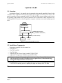
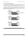
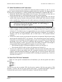
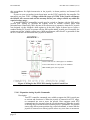
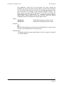
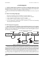
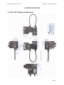
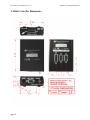
Computer Controlled
PAN-TILT UNIT
Model PTU-D46
USER’S MANUAL
Version 2.15
www.flir.com/MCS
Pan-Tilt Unit (Model PTU-D46) User’s Manual, Version 2.15,
November 22, 2006
©1991,2006, 2011 by FLIR Motion Control Systems, Inc., 890C
Cowan Road, Burlingame, California 94010, (650)692-3000, FAX:
(650)692-3930, URL: http://www.flir.com/MCS.
All rights reserved. Protected under U.S. Patents 5463432 and
5802412. No part of this book may be reproduced, stored in a
retrieval system, or transcribed, in any form or by any means,
electronic, mechanical, photocopying, recording, or otherwise,
without the prior written permission of FLIR Motion Contorl
Systems, Inc.
The information in this manual is subject to change without notice
and, except for the warranty, does not represent a commitment on
the part of FLIR Motion Control Systems, Inc. FLIR Motion
Control Systems, Inc. cannot be held liable for any mistakes in this
manual and reserves the right to make changes.
Table of Contents
Pan-Tilt User’s Manual Version 2.15
1
INTRODUCTION ...................................................................................................1
2
QUICK START........................................................................................................2
2.1
Overview......................................................................................................2
2.2
Installation Components ..............................................................................2
2.3
Basic Setup Steps.........................................................................................3
3
INSTALLATION & INITIAL SETUP ....................................................................4
3.1
Power Source ...............................................................................................4
3.2
RS-232 Cable and Host Settings..................................................................5
3.3
Initial Installation and Connections .............................................................6
3.4
Basic Pan-Tilt Unit Commands ...................................................................6
3.5
Mounting Your Camera or Other Payload ...................................................7
4
SPECIAL CONFIGURATIONS..............................................................................8
4.1
High-Speed Operation .................................................................................8
4.2
High-Payload Operation ..............................................................................8
4.3
Battery-Powered Operation .........................................................................8
5
PTU OPTIONS ........................................................................................................9
5.1
EIO Option: Expansion Serial Ports and Control ........................................9
5.1.1 Select Serial Communications Target ..............................................9
5.1.2 Configuring Expanded Serial Port Communications.....................10
5.1.3 Attaching a Mouse/Trackball to an Expanded Serial Port.............11
5.1.4 Expansion Analog Joystick Control Port and Pin-Out ..................11
5.1.4.1 Expansion Analog Joystick Commands ............................12
6
NETWORKING ....................................................................................................14
6.1
Basic Networking Setup Steps...................................................................14
6.2
PTU Network Connections ........................................................................14
6.3
PTU Network Software Commands ..........................................................15
6.3.1 Unit Network ID ............................................................................15
6.3.2 Unit Select/Deselect.......................................................................16
A.
SPECIFICATIONS ................................................................................................17
A.1
Pan-Tilt Mechanical Dimensions..............................................................17
A.2
D46 Controller Dimensions .......................................................................18
REGULATORY INFORMATION.........................................................................20
LIMITED WARRANTY .......................................................................................22
PTU-D46 User’s Manual (v2.15)
INTRODUCTION
1 INTRODUCTION
The Computer-Controlled Pan-Tilt Unit from FLIR Motion Control Systems, Inc. (FLIR
MCS) provides low-cost, fast and accurate positioning of cameras and other payloads. Some
general features:
• Simple to command from any RS-232 terminal or computer
• Small form factor
• PTU-D46-17 performance highlights:
• Load capacity over 6 lbs. (2.72kg)
• Speeds over 300°/second
• Resolution of 0.129 degrees (46.29 arc seconds)
• PTU-D46-70 performance highlights:
• Load capacity over 9 lbs. (4.08kg)
• Speeds over 60°/second
• Resolution of 0.0032 degrees (11.57 arc seconds)
• Precise control of position, speed & acceleration
• On-the-fly position and speed changes
• Self calibration upon reset
• Power consumption can be controlled from host
• ASCII command mode for simplicity, binary commands available for efficient program
control
• Constant current DMOS motor drives for increased performance and control
• DC power input from an unregulated source
The PTU-D46 series is electrically and software compatible with the earlier PTU-46 series. The
PTU-D46 provides a smaller controller, higher payload capacity, greater power control, smoother
movement, flash reprogrammability, and cooler operation for hot or more hostile environments.
Applications of the PTU include:
• Robotics & computer vision
• Webcam
• Security camera control
• Teleconferencing
• Advanced monitoring systems
• Tracking
• Photography, videography and special effects.
In addition, the PTU has flexible connectivity options.
This User’s Manual provides information needed to set up and operate the PTU unit. The
next section provides a quick overview to allow you to get started as quickly as possible. More
detailed technical information is provided in the remaining sections.
page 1
QUICK START
PTU-D46 User’s Manual (v2.15)
2 QUICK START
2.1 Overview
As shown in Figure 1, the pan-tilt unit is connected to the pan-tilt controller. Power for the
controller can be supplied from an optional AC/DC power supply or a battery power source. The
pan-tilt controller accepts commands via RS-232 or RS-485 from a host computer, and it drives
the position of the pan-tilt unit. A pan-tilt controller can be connected to other controllers via a
multidrop RS-485 network so that a single host computer serial port can control multiple pan-tilt
units.
payload
Pan-Tilt Unit
(model PTU)
Pan-Tilt Controller
(model PTU-D46)
RS-232
Host
Computer
8-30VDC power source
(e.g., model PT-PS-INT30V)
RS-485 (controller network)
other PTU
or host
Figure 1: Pan-Tilt System Overview.
2.2 Installation Components
•
•
•
•
•
Components supplied with this manual are:
Pan-Tilt Unit
Pan-Tilt Controller
Pan-Tilt Cable
(optional) AC/DC Power Supply (model PT-PS-INT30V)
(optional) C Programmer’s Interface (model PTU-CPI)
Only move the pan-tilt axes using the knobs mounted on the pan-tilt unit motors
while the unit is powered off. Manual rotation of pan-tilt axes (called backdriving)
can degrade unit performance and accuracy.
CAUTION! Removing power by pulling the plug can damage the PTU-D46.
page 2
PTU-D46 User’s Manual (v2.15)
QUICK START
2.3 Basic Setup Steps
The following outlines the basic pan-tilt set-up and installation steps. Section 3 details each
of these steps.
1. Obtain a DC power source. The optional Pan-Tilt Power Supply (model PT-PS-INT30V) or
an alternate power source may be used (see Sections 3.1 and 5).
2. An RS-232 cable is provided to connect your terminal or host computer to the Pan-Tilt
Controller (see Section 3.2).
3. The pan-tilt unit should then be connected to power, the RS-232 host, and the controller.
Pan-tilt operation can then be tested (See Section 3.3).
4. Section 3.4 describes some basic pan-tilt commands to get you going. The separate
Command Reference Manual provides a full description of all pan-tilt unit commands and
queries.
5. You can now mount your payload (e.g., camera) on the pan-tilt unit (see Section 3.5).
Section 4 describes how to configure your pan-tilt for high speed operation.
page 3
INSTALLATION & INITIAL SETUP
PTU-D46 User’s Manual (v2.15)
3 INSTALLATION & INITIAL SETUP
This section describes the basic installation and setup steps required to get your pan-tilt
operational as quickly as possible.
3.1 Power Source
A DC power source connects to the 2.1mm coaxial connector on the Pan-Tilt Controller. Two
DC power source options are available:
• AC Source
• DC source: 9-30VDC (unregulated) capable of 13W continuous
To use an AC source, simply plug the optional Pan-Tilt Power Supply (model PT-PSINT30V) connector to the controller and plug it into an AC power outlet.
Alternative power sources that can supply at least 17W continuous can be used by attaching a
2.1/5.5mm coaxial connector cable to a suitable DC power source (e.g., battery power, vehicle
power, or an AC/DC converter). In order to achieve the highest pan-tilt unit performance, use the
highest motor voltage within the allowable range. To achieve the quietest pan-tilt operation, use a
lower motor voltage (e.g., 12VDC). Operation at 12VDC limits the highest unloaded pan-tilt
speed to about 2/3 the rated maximum speed (i.e., 200°/second for the PTU-D46-17, and 40°/
second for the PTU-D46-70). Figure 2 shows the DC power connector wiring.
CAUTION! When wiring your own power source, failure to comply with
wiring and power source requirements described in this manual can result
in decreased unit performance or damage not covered under the limited
warranty.
9-30VDC
Figure 2: DC plug uses a 2.1/5.5mm connector
If you are providing your own DC power source, the power source must never supply more than
3A of current, and if so, you must add a 3A Fast-Blow fuse in series with your DC power
source. For example, when connecting to a vehicle battery or lighter plug, you must fuse the
incoming DC source. Failure to properly fuse your input power source could cause overloading of
internal protection devices, pose a safety hazard, or void product warranties.
CAUTION! Removing power by pulling the plug can damage the PTU-D46.
page 4
PTU-D46 User’s Manual (v2.15)
INSTALLATION & INITIAL SETUP
3.2 RS-232 Cable and Host Settings
An RS-232 terminal or host computer connects to the female DB-9 connector on the Pan-Tilt
Unit Controller (PTU-C). The host terminal or computer should be set to 9600 baud, 1 start bit, 8
data bits, 1 stop bit, and no parity. Hardware handshaking and XON/XOFF are not used.
The RS-232 connections to the Pan-Tilt Controller female DB-9 are: TxD (pin 2), RxD (pin
3), and GND (pin 5). You will need to obtain a cable that connects the host RS-232 port to the
controller DB-9 connector. Figure 3 shows cable configurations for some common computer
hosts. Since TxD and RxD assignments to pins 2 and 3 can vary on host computers, try using a
null modem if your initial connection does not work.
IBM PC, XT
Asynch Card DB-25S
TxD (pin 2)
RxD (pin 3)
GND (pin 7)
DTR (pin 20)
DSR (pin 6)
PTU-C
(female DB-9)
RxD (pin 3)
TxD (pin 2)
GND (pin 5)
(pin 4)
(pin 6)
IBM AT
Asynch Card DB-9S
RxD (pin 2)
TxD (pin 3)
GND (pin 5)
DTR (pin 4)
DSR (pin 6)
PTU-C
(female DB-9)
TxD (pin 2)
RxD (pin 3)
GND (pin 5)
(pin 4)
(pin 6)
Apple Macintosh
8 Pin Mini-DIN
TxD (pin 3)
RxD (pin 5)
GND (pin 4)
DTR (pin 1)
DSR (pin 2)
PTU-C
(female DB-9)
TxD (pin 2)
RxD (pin 3)
GND (pin 5)
(pin 4)
(pin 6)
Null modem may
be required.
Figure 3: RS-232 Pan-Tilt Controller Connection to Common Hosts
page 5
INSTALLATION & INITIAL SETUP
PTU-D46 User’s Manual (v2.15)
3.3 Initial Installation and Connections
If you have the power source and RS-232 cables described in Sections 3.1 and 3.2, you are
ready to connect the pan-tilt unit components together and test its operation. We suggest that you
do not mount your payload (e.g., camera) until the initial installation is completed and tested.
1. Mount the Pan-Tilt Unit using standard #1/4-20 screws. The unit has two front and two
bottom threaded holes. A camera tripod may be used for bottom mounting.
2. Connect the Pan-Tilt Unit to the Pan-Tilt Controller using the supplied cable. Note that the
smaller cable connector attaches to the pan-tilt unit, and the larger cable connector attaches
to the controller box. Securely screw the cable connectors to the pan-tilt unit and controller.
CAUTION! Failure to securely screw the supplied cable
connectors to the pan-tilt unit and controller can cause damage to
the controller when power is applied.
3. Connect the host terminal or computer to the Pan-Tilt Controller (PTU-C) using the RS-232
cable you supply (as described in Section 3.2). Configure the host RS-232 port as described
in Section 3.2. For initial set-up, it is suggested that you use a terminal or terminal emulator
on a host computer to become acquainted with the unit and its commands. For example, in
Windows you can use HyperTerminal, and in UNIX there is TIP (terminal interface
program).
4. You are now ready to power up the pan-tilt unit and test its operation. Plug the power plug
into the pan-tilt controller PTU-C (see Section 3.1 for a discussion of power source options).
Upon power up, introduction text should appear on your screen, and the pan-tilt unit should
go through a reset cycle. This reset is completed when an asterisk (‘*’) appears. If the unit
did not reset properly, recheck your power source and cabling. If the unit went through its
reset procedure, but no text or garbled text appears on your screen, then:
• Check that the host RS-232 host port settings are correct (see Section 3.2)
• Check that the RS-232 cable is correct for your host (see Section 3.2)
5. You are now connected to the pan-tilt controller. The next section describes some basic
commands to help you get going, and a full command description may be found in the
separate Command Reference Manual. We suggest that you exercise the unit and become
familiar with its operation and commands before mounting your payload (e.g., camera) as
described in Section 3.5.
3.4 Basic Pan-Tilt Unit Commands
Below are some pan-tilt commands that will familiarize you with the pan-tilt unit and its
operation:
pp2500 *
tp-900 *
ps2500 *
pp0 *
This sets the pan axis to position 2500, the tilt axis to position -900, the pan speed to 2500
positions a second, and sets the pan position back home. A detailed description of pan-tilt
commands and queries may be found in the separate Command Reference Manual.
page 6
PTU-D46 User’s Manual (v2.15)
INSTALLATION & INITIAL SETUP
3.5 Mounting Your Camera or Other Payload
Your camera or other load attaches to the top mounting plate on the Pan-Tilt Unit. A centered
hole and standard #1/4-20 bolt and nut is provided for simple mounting of cameras. Custom
mounting is easily performed by removing the four hex screws holding the mounting plate,
machining or drilling it to your requirements, and re-screwing the mounting plate back on the
pan-tilt unit.
Though the pan-tilt unit is rated to a maximum load of 6 lbs, the distribution of the load
clearly affects the actual load capable of being moved by the pan-tilt unit. The steps to determine
whether your load is within the maximum load capacity and dynamics are:
• Mount your load. Attempt to center the load’s center of mass close to the hole in the
mounting plate. Ensure that the load is securely attached to the mounting plate.
• First move the pan axis through its range to test whether the pan-tilt can handle the load
(e.g., enter “dr pp2700 a pp-2700 a pp0 ”). A load that is too heavy or moved too
quickly will cause the unit to lose synchrony, and this will be accompanied by an audible
“rrrr” sound from the pan-tilt unit motors.
• If your load passed the pan axis load test, you can then test the tilt axis load handling
capability. Because the tilt axis requires more power to move the load, it is more likely to
lose synchrony for excessive loads or load weight distributions. Move the tilt axis through
its range to test whether the pan-tilt can handle the load (e.g., enter “dr tp-900 a
tp600 a tp0 “). A load that is too heavy or moved too quickly will cause the unit to lose
synchrony, and this will be accompanied by an audible “rrrr” sound from the pan-tilt unit
motors.
• If your load fails the above pan or tilt axis load handling tests, contact FLIR MCS for further
assistance.
• If your load passes the above pan and tilt axis load handling tests, you are ready to begin
controlling you load using the commands described in the separate Command Reference
Manual.
• The initial pan-tilt unit parameters ensure the highest load movement torque that can be
generated from the pan-tilt unit. Significantly faster or lower power control can be obtained
via commands to the pan-tilt unit. The speed and acceleration of a mechanical system
depends upon the inertial properties of your load. The ability of the pan-tilt unit to
successfully move your load without losing synchrony depends upon the inertial load
factors and their relationship to power supply voltage, unit speed, acceleration, position,
motor torque, etc. Section 4 discusses how to configure pan-tilt parameters to achieve more
optimal pan-tilt unit performance for your load.
If these steps do not resolve the problem, try the following steps:
1. Try reducing PTU speed.
2. Reduce PTU acceleration.
3. Move the payload closer to the center of rotation.
4. Call FLIR Motion Control Systems for further assistance if needed.
page 7
SPECIAL CONFIGURATIONS
PTU-D46 User’s Manual (v2.15)
4 SPECIAL CONFIGURATIONS
4.1 High-Speed Operation
This section discusses how to improve high speed pan-tilt unit performance for your load.
The primary factors that affect high speed operation are:
• Load weight, weight distribution and dynamics
• Desired upper speed limit
• Rate of acceleration
• The base (start-up) speed
• The voltage of the source power supply. Use of the highest available voltage in the range 930VDC significantly improves axis speed and acceleration performance.
• The in-motion power mode and stationery power mode.
• Multiaxis dynamics. Simultaneously moving the tilt and pan axes affects the forces exerted
on the pan axis.
High speed operation tests should always begin on each axis in isolation. When the best
performance for each axis in isolation is understood, high speed operation of simultaneous pan-tilt
axis movements can be performed.
An example configuration string for high speed operations is:
PA9000 PU6000 TA9000 PU6000 DS
4.2 High-Payload Operation
This section discusses how to improve high payload weight operation of the pan-tilt. The
payload factors listed in the previous section outlined factors that affect payload carry capacity.
The primary factor affecting payload capacity is the tilt axis, as it is a lever which is an
efficient force multiplier. The primary means to increase payload capacity are:
• Configure the pan-tilt controller for maximum torque. An example configuration string to
maximize payload capacity is:
PU2000 PA2000 PB60 TU2000 TA2000 TB60 PMR TMR %%1R600 DS
•
•
•
•
If your move duty cycle is less than 50%, you can alternatively use the highest move current
settings and regular hold power settings of PMH TMH PHR THR .
Move the payload center of gravity closer to the tilt axis
Use a higher voltage power source in the range 9-30VDC
Use the PTU-D46-70 which has a higher payload rating than the PTU-D46-17
Determine if the payload can be modified to lighten it.
4.3 Battery-Powered Operation
The Pan-Tilt Unit and Controller have been designed for battery powered operation. Battery
powered applications need to conserve power when possible. The pan-tilt unit has commands to
control pan-tilt motor power consumption while in transit and when stationary. Careful testing can
be used to determine the lowest power modes that assure your load can be moved and held
without losing synchrony (see Section 3.5).
page 8
PTU-D46 User’s Manual (v2.15)
PTU OPTIONS
5 PTU OPTIONS
5.1 EIO Option: Expansion Serial Ports and Control
In many cases, other serial devices are attached or proximal to the pan-tilt. In these cases, you
can directly connect these other devices to your host computer serial ports. Doing this requires
more serial ports on your host computer, and additional serial cabling is required. To reduce the
host computer port and cabling requirements, an option for the PTU Controller is provided which
adds two additional serial ports to the PTU controller.
A mouse or trackball can be connected to one of the expanded serial ports to allow direct user
control of pan-tilt position without requiring an external host computer.
A PTU controller with additional serial ports may be identified by the two DB9 male
connectors on the controller housing, and the firmware version number will include a “/D” (see
Section 4.5.5 for querying PTU firmware). These additional RS232C DTE ports are designated
Channel A (CHA) and Channel B (CHB).
The serial port expansion channels are controlled from the main PTU controller serial port.
CHA/CHB RS232C ports may be configured from the PTU controller serial port to set expanded
port baud rate, data bits, parity, and handshaking. Each channel operates independently, and the
PTU controller fully buffers bi-directional data flow to allow for communications rate mismatch.
Point-to-point communications between the PTU controller serial port and an expansion channel
(e.g., CHB) is initiated by the host computer. Point-to-point communications is broken upon
command from the host computer.
Communications from a serial device attached to an expansion serial channel is buffered (at
least 200 characters). When hardware handshaking is not used, this buffer can overflow, so care
should be taken to ensure that attached devices do not exceed the buffer size before its data on the
serial channel is read by the host computer.
5.1.1 Select Serial Communications Target
Description
Command establishes point-to-point communications between the host
computer connected to the PTU controller serial port and the expanded serial
port (CHA/ CHB) or pan-tilt controller. When an expansion port channel is
selected, the host computer is no longer communicating with the PTU
controller, but instead with the external device connected to the expanded
serial port. To resume communicating with the PTU controller, the host
computer need only issue a command selecting the PTU controller as its
desired communications target.
The baud rate of an expansion port does not affect the communications
with the serial port connecting the host computer to the pan-tilt controller
(which defaults to 9600 baud).
Syntax
Establish communications with CHA:
@A<delim>
Establish communications with CHB:
@B<delim>
Resume communications with the PTU controller: @<delim>
The modified commands below ensure that <# raw bytes> bytes will be
passed directly from the host computer to the expanded serial port without
any attempt to change the communications target. This allows strings like @B
to be embedded in communications between the host computer and the
expanded serial port device, without causing communications between the
two to be inadvertently interrupted.
page 9
PTU OPTIONS
PTU-D46 User’s Manual (v2.15)
Establish communications with CHA: @A<# raw bytes><delim>
Establish communications with CHB: @B<# raw bytes><delim>
where <# raw bytes> is the number of bytes to follow that will be received
from the host computer which will not be scanned for changes in the serial
communications target.
Example
@ *
PP * Current pan position is 0
@A *
This text is sent directly to the serial device on CHA
@B *
This text is sent directly to the serial device on CHB
@A20 *
This @B text is sent to CHA without choosing CHB
@ *
PP * Current pan position is 0
Related Topics
• To set expanded serial port communications parameters: See Section 5.1.1
5.1.2 Configuring Expanded Serial Port Communications
Description
Command specifies the communications parameters for an expanded serial
port RS232C communications. These commands only affect the serial data
rates for the expansion port connected to the external serial device; the PTU
controller serial port default communicates at 9600 baud, 8 databits, no
parity, and no handshaking. See section 4.7 for modifying host port
communications speed.
Syntax
@A(<baud>,<databits>,<parity>,<handshaking>)<delim>
@B(<baud>,<databits>,<parity>,<handshaking>)<delim>
where A and B indicate RS232C expansion port CHA and CHB, and:
<baud> may be 300, 1200, 2400, 4800, 9600 or 19200 bits
per second
<databits> may be 7 or 8 databits per byte
<parity> is case insensitive and may be N (none), E (even), or O (odd)
<handshaking> is case insensitive and may be N (none), H (hardware
handshaking), X (XON/XOFF software handshaking), or F (both
hardware/software handshaking)
Example
The following command sets the expansion serial port channel CHA to a
baud rate of 9,600 bits/second, 8 data bits per byte, no parity, and no
handshaking:
@A(9600,8,N,n) *
The following command sets the expansion serial port channel CHB to a
baud rate of 19,200 bits/second, 8 data bits per byte, no parity, and hardware
handshaking:
@B(19200,8,n,H) *
page 10
PTU-D46 User’s Manual (v2.15)
PTU OPTIONS
Related Topics
• To communicate with an expansion serial port channel : See Section 5.1.1
5.1.3 Attaching a Mouse/Trackball to an Expanded Serial Port
Description
A mouse or trackball can be connected to one of the expanded serial ports to
allow direct user control of pan-tilt position without requiring an external
host computer. When a host computer and mouse/trackball are both attached
and enabled, the most recent pan-tilt movement command is processed. The
host computer can control when the mouse/trackball is enabled, and the host
can query the pan-tilt position while the pan-tilt is actively being controlled
by the mouse/trackball.
Any Microsoft format compatible mouse or trackball can be used.
These devices default the communications to be 1200 baud, 7 bits per
character, no parity and hardware handshaking (which powers the device).
The default is for mouse/trackball control is enabled for CHA. If the
mouse/trackball is enabled for both CHA/CHB expansion ports, only the
CHA port will be used to effect pan-tilt control. A Default Save (see Section
4.5.2) will restore this state at power-up. Whenever expansion port
communications are modified using the commands in Section 5.1.2, mouse/
trackball control is disabled; the command in this section must be used to
reenable mouse/trackball control.
Syntax
@A(M)<delim>
@B(M)<delim>
where A and B indicate RS232C expansion port CHA and CHB. @A(M) is
the system default.
Example
PH * Pan in LOW hold power mode
@A(M) *
DS *
Configures the pan-tilt controller to look for a mouse/trackball on the CHA
expansion port. After power up,
V * Pan-Tilt Controller v2.12.1d1(C14/EM), (C)2003 FLIR MCS, Inc., All Rights Reserved
where “/EM” indicates the presence of the EIO option and the detection of a
Mouse/trackball.
Related Topics
• To change expansion serial port communications : See Section 5.1.2
5.1.4 Expansion Analog Joystick Control Port and Pin-Out
The PTUC-EIO provides an analog joystick control port using a DB15 female receptacle.
FLIR MCS offers an analog joystick for use with this EIO port (model PT-EIO-JOY-DB).
A digital mouse/trackball using the EIO serial ports, described above, is superior to analog
voltage controls, though an analog voltage control option is provided for those applications in
which voltage control is required. The wiring diagram for the analog voltage control port is shown
in Figure 4. X controls the pan axis and Y controls the tilt axis. X=0VDC is maximum pan left,
and X=5VDC is maximum pan right. Similarly, Y=0 is maximum tilt down, and Y=5VDC is
maximum tilt up. For both axes, about 2-3VDC is a deadband in which no axis movement occurs;
page 11
PTU OPTIONS
PTU-D46 User’s Manual (v2.15)
this accomodates for slight inaccuracies in the joystick, its home position, and internal A/D
conversion.
If you wire your own analog joystick port input, use the 5VDC supplied by the controller. Do
not supply your own 5VDC. A voltage outside the range of 0-5VDC to the joystick will damage
the internal A/D converter and void the warranty. Ensure your voltage controls stay within the
required voltage range.
A standard IBM PC compatible joystick may be rewired to function with the EIO analog
joystick port. Analog PC joysticks are actually wired as variable resistors rather than
potentiometers. (Historically, this is because A/D converters were expensive when the PC joystick
was designed, so they kludged a shift register to do the job.) Figure 4 shows how to rewire a
standard analog PC joystick to operate with the EIO option analog joystick port. Essentially, the
rewire converts the variable resistor into a 100K potentiometer, and switch 2 is grounded so that
the PTU controller can determine that a joystick is attached.
JOYSTICK
Vcc
Y_POT
100K
X_POT
100K
GND
Vcc
GND
button1
GND
Vcc
shield
X: 0V is max left, 5V is max right, 2-3V deadband
Y: 0V is max down, 5V is max up, 2-3V deadband
SW: normally open, close to ground
joystick
DB15M
Figure 4. Wiring for the PTUC-EIO Analog Joystick Control Port
5.1.4.1 Expansion Analog Joystick Commands
Description
Two PTU controller commands were added to support the EIO joystick port
to activate and deactivate it. When the joystick is centered in its X-Y range,
no commands are sent to move the pan-tilt. Host computer serial PTU
commands may be executed when the joystick is centered. When the joystick
is moving, they override the most recent serial PTU commands. The joystick
center range allows some position slop, called a deadband, to ensure that the
joystick is centered even when joystick values vary over time or movement.
page 12
PTU-D46 User’s Manual (v2.15)
PTU OPTIONS
This deadband is about 20% of each joystick axis range. Outside the
deadband, the joystick position is linearly related to speed of the pan and tilt
axes. The fastest joystick speed is set by the lowest Upper Speed Limit for the
pan and tilt axes. For example, for the command “PU6000 TU4000 “, the
fastest joystick movement will be 4000 pos/sec. Note that if you change the
Upper Speed Limit, you must issue a “JE “ command for the new limit to
affect joystick control speeds. In this way, you can control the joystick
commanded speeds by setting desired Upper Speed Limits.
Syntax
JE<delim>
JD<delim>
Enable EIO analog port joystick control
Disable EIO analog port joystick control
Example
JE *
DS *
Activates EIO analog port joystick control, and Default Saves so that joystick
control is activated upon power up of the pan-tilt.
Related Topics
• To change pan-tilt axis upper speed bounds, refer to the separate Command
Reference Manual
page 13
NETWORKING
PTU-D46 User’s Manual (v2.15)
6 NETWORKING
The PTU controller lets you connect up to 127 PTUs to a single host computer port. Your
host computer can then address each PTU on the network as though the PTU were the only
controller attached to the host. In this way, it is simple to migrate existing code developed for a
single PTU to a network of PTUs controlled by a single host computer.
This section describes the basic installation and setup steps required to network your pan-tilt
units.
6.1 Basic Networking Setup Steps
1.
2.
3.
4.
The steps in networking your PTU controllers to your host computer are:
Sketch out the physical placement of your PTU controllers and host computer.
Assign a unique network ID number to each PTU controller.
Connect the PTU controllers and host computer to the PTU network.
Test the configuration by addressing each PTU controller by its unit ID and commanding
and querying its attached pan-tilt unit.
6.2 PTU Network Connections
Figure 5 illustrates how PTU controllers can be networked and connected to a host computer
via its RS-232 port. Each PTU controller has a built-in RS-232 to RS-485 converter, and the host
computer can be connected to the RS-485 controller network by simply connecting to the RS-232
connector on a PTU controller box. The PTU controllers are then connected together via an RS485 multi-drop network (full duplex).
R S - 4 8 5 M u l t i - D ro p N e t w o r k
120Ω 1% terminator
120Ω 1% terminator
(full duplex)
•••
HOST
COMPUTER
net/termin.
network
PTU-NCONN
•••
net/termin.
network
PTU-NCONN
PTU
Controller
network
net/termin.
PTU-NCONN
PTU
Controller
Figure 5: Making PTU Network Connections
The basic start configuration for networking PTU-controllers may be made using the PTU
Network Starter Kit (model PTU-D46-NET-SK). This starter kit includes two Y-connectors used
to connect to each of two PTU controllers, a data connection cable, and two network terminators.
Additional PTU controllers may be networked using the PTU Network Addition Unit Kit (model
PTU-D46-NET-AU), and this includes an additional Y-connector and data connector cable.
Figure 6 shows the wiring from the PTU RS-485 controller network receptacle (RJ-12,
6P6C). Several issues are important to note when you make your own data cables. First, use a
page 14
PTU-D46 User’s Manual (v2.15)
1 Shield
2 R+
3 R4 T5 T+
6 Shield
NETWORKING
1 2 3 4 5 6
view looking into
RJ12 (6P6C) receptacle
Figure 6: RS-485 Wiring
good quality cable. Though a good quality telephone cord cable can be used, use of a twisted pair
cable is highly recommended. A twisted pair whose impedance is about 100Ω is typically used for
longer RS-485 runs. The twisted pair provides good noise immunity owing to the relative signals
used by the RS-485 standard.
For some applications, the host computer may directly provide RS-485 full-duplex I/O. In
this case, you may use the RS-485 wiring diagram shown in Figure 6 to directly connect your host
computer to the PTU controller network. For computers with only RS-232, RS-485 connections
may be simply made using an external RS-232 to RS-485 converter. FLIR MCS has tested/
qualified two coverters: ATEN IC-485S and Moxa A50 which both require a flipped RJ-12
connector (such as a standard phone cord). It is important to note that the network should be
terminated using 120Ω 1% resistors to protect against signal ringing on the network. Termination
is achieved by placing the resistors between the RS-485 Transmit+/Transmit- and Receive+/
Receive- wires at each end of the multidrop wiring network.
6.3 PTU Network Software Commands
This section describes the pan-tilt command set used to configure, set and query the network
configuration of your PTU controllers.
6.3.1 Unit Network ID
Description
Specify or query the PTU controller network unit ID number. By default, the
PTU unit ID is set to zero which indicates the PTU controller is not
networked, and the PTU controller is in the default interactive
communications mode. When assigning a unit ID number to a controller, the
unit ID number should be unique, the controller should be the only PTU
controller attached to the host computer or terminal (otherwise other
controllers may be set to the same unit ID number). A unit ID of zero may be
used to put a PTU controller back in interactive (non- networked) mode.
Syntax
Query current PTU network unit ID:
U<delim>
Set PTU to interactive mode (non-networked): U0<delim>
Set PTU network unit ID:
U<unit_ID><delim>
where 1 ≤ <unit_ID> ≤ 127
page 15
NETWORKING
PTU-D46 User’s Manual (v2.15)
Example
The following queries a PTU unit ID, then sets and stores the unit ID
configuration so that upon power-up the new unit ID will be used.
U * Unit ID is 0
U1 *
U * Unit ID is 1
U1 *
DS *
Related Topics
• Unit Select/Deselect: See Section 6.3.2.
6.3.2 Unit Select/Deselect
Description
Command is used to select the PTU to be controlled. A PTU controller will
execute incoming host computer commands only when the preceding unit_ID
selected by the host is (a) equal to the PTU controller’s assign unit ID, or, (b)
equal to 0. A host computer can broadcast instructions to be executed by all
PTO controllers using unit_ID=0. Only one PTU controller can provide
feedback to the host computer at a time. A PTU controller provides feedback
to the host computer only when the host computer has selected its unit ID. A
PTU controller buffers its outgoing data until the host computer polls it -- the
current PTU controller buffer size is about 100 bytes.
Syntax
Select a PTU controller for bi-directional data: _<unit_ID><delim>
Broadcast to all networked PTU controllers:
_0<delim>
where 0 ≤ <unit_ID> ≤ 127
Example
_1
pp300 *
_0
pp300
_1
*
Related Topics
• Unit Network ID: See Section 6.3.1
page 16
PTU-D46 User’s Manual (v.2.14.1)
Appendix A.: SPECIFICATIONS
A. SPECIFICATIONS
A.1 Pan-Tilt Mechanical Dimensions
page 17
PTU-D46 User’s Manual (v2.14.1)
A.2D46 Controller Dimensions
page 18
Appendix A.: SPECIFICATIONS
PTU-D46 User’s Manual (v.2.14.1)
Appendix A.: SPECIFICATIONS
page 19
REGULATORY INFORMATION
Electromagnetic Interference (EMI) is any signal or emission, radiated in free space or conducted along power or signal leads that enganders the function of a radio navigation or other safety service or seriously degrades, obstructs, or
repeatedly interrupts a licensed radio communications service.
Class A
Class A equipment has been tested and found to comply with the limits for a Class A digital device, pursuant to Part
15 of the FCC Rules. These limits are designed to provide reasonable protection against harmful interference in a
commercial environment. This equipment generates, uses and can radiate radio frequency energy and, if not installed
and used in accordance with the instructions, may cause harmful interference to radio communications. However,
there is no guarantee that interference will not occur in a particular installation. Operation of this equipment in a residential area is likely to cause harmful interference, in which case the user will be required to correct the interference
at his/her own expense.
All FLIR MCS products have been tested to comply with FCC Class A requirements.
Class B
Class B equipment has been tested and found to comply with the limits for a Class B digital device, pursuant to Part
15 of the FCC Rules. These limits are designed to provide reasonable protection against harmful interference in a residential installation. This equipment generates, uses and can radiate radio frequency energy and, if not installed and
used in accordance with the instructions, may cause harmful interference to radio communications. However, there is
no guarantee that interference will not occur in a particular installation. If this equipment does cause harmful interference to radio or television reception, which can be determined by turning the equipment off and on, the user is
encouraged to try to correct the interference by one or more of the following measures:
•
Reorient or relocate the receiving antenna.
•
Increase the separation between the equipment and receiver.
•
Connect the equipment into an outlet on a circuit different from that to which the receiver is connected.
•
Consult the dealer or an experienced radio/TV technician for help.
FLIR MCS D46 pan-tilt devices using a cable length of 7’ or less, either with or without the EIO option, and using the
PT-PS-INT30V power supply (including PT-PS-FERRITE) have been tested to comply with FCC Class B requirements.
Caution: Changes or modifications of this equipment not expressly approved by manufacturer could result in violation of Part 15 of the Federal Communications Commissions rules. The FCC has prepared the following booklet:
"How to Identify and Resolve Radio-TV Interference Problems.” It is available from the US Government Printing
Office, Washington DC, 20402. Stock Number 004-00-00345-4.
FCC Notice
According to 47CFR, Parts 2 and 15, Class B Computer Peripherals:
This device complies with Part 15 of the FCC Rules. Operation is subject to the following two conditions: (1) This
device may not cause harmful interference, (2) This device must accept any interference received including interference that may cause undesired operations.
page 20
page 21
LIMITED WARRANTY
FLIR MCS, Inc. warrants this product against defects in material or workmanship, as follows:
For a period of one year from date of purchase, FLIR MCS, Inc. will repair the defective product
and provide new or rebuilt replacements at no charge. Warranty repairs require the issuance of an
repair authorization number from FLIR MCS prior to the return of merchandise, and the buyer
assumes responsibility for freight charges.
After the one year period, you must pay for all parts, labor and freight.
This warranty does not cover any damage due to accident, misuse, abuse or negligence. You
should retain your original bill of sale as evidence of the date of purchase.
REPAIR OR REPLACEMENT AS PROVIDED UNDER THIS WARRANTY IS THE
EXCLUSIVE REMEDY OF THE PURCHASER. FLIR MCS SHALL NOT BE LIABLE FOR
ANY INCIDENTAL OR CONSEQUENTIAL DAMAGES FOR BREACH OF ANY EXPRESS
OR IMPLIED WARRANTY ON THIS PRODUCT, EXCEPT TO THE EXTENT PROHIBITED
BY APPLICABLE LAW, ANY IMPLIED WARRANTY OF MERCHANTABILITY OR
FITNESS FOR A PARTICULAR PURPOSE ON THIS PRODUCT IS LIMITED IN
DURATION TO THE DURATION OF THIS WARRANTY.
Some states do not allow the exclusion or limitation of incidental or consequential damages, or
allow limitations on how long an implied warranty lasts, so the above limitations or exclusion
may not apply to you. This warranty gives you specific legal rights, and you may also have other
rights which vary from state to state.
page 22