1
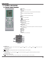
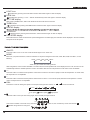
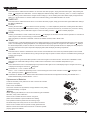
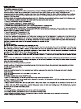
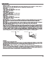
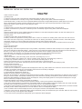
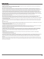
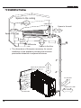
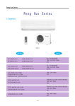
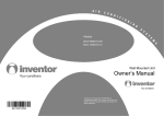
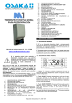
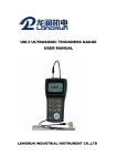
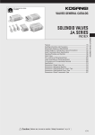
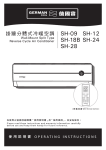
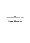
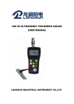
USER/INSTALLATION MANUAL
MODELS:
QSFMI-09A
QSFMI-12A
QSFMI-18A
1
ON/OFF
Press it to start or stop operation.
2
MODE
Press it to select operation mode (AUTO/COOL/DRY/FAN/HEAT).
3
+
Press it to increase temperature setting.
4
-
Press it to decrease temperature setting.
5
2
1
FAN
Press it to set fan speed.
6
3
4
6
5
9
10
Press it to set swing angle.
7
11
12
13
TIMER ON
Press it to set auto-on timer.
7
8
8
9
TIMER OFF
Press it to set auto-off timer.
CLOCK
Press it to set clock.
14
10
X-FAN
X-FAN is the alternative expression of BLOW for the purpose
of understanding.)
11
12
13
14
TEMP
TURBO
SLEEP
LIGHT
Press it to turn on/off the light.
25
24
23
22
21
15
16
20
17 18 19
15
MODE icon:
If MODE button is pressed, current operation mode icon
(AUTO),
( COOL),
(DRY),
(FAN) or
(HEAT is only for heat
pump models) will show.
16
SLEEP icon :
is displayed by pressing the SLEEP button. Press this button again to clear the display.
17
TEMP icon:
Pressing TEMP button,
(set temperature),
(indoor ambient temperature),
(outdoor ambient temperature) and blank is
displayed circularly.
18
Up & down swing icon:
is displayed when pressing the up & down swing button. Press this button again to clear the display.
19
LIGHT icon:
is displayed by pressing the LIGHT button.Press LIGHT button again to clear the display.
20
LOCK icon:
is displayed by pressing "+" and “-” buttons simultaneously.Press them again to clear the display.
21
SET TIME display:
After pressing TIMER button, ON or OFF will blink.This area will show the set time.
22
TURBO icon:
23
DIGITAL display:
is displayed when pressing theTURBO button.Press this button again to clear the display.
This area will show the set temperature. In SAVE mode,"SE" will be displayed. During defrosting operation, “H1” will be displayed.
24
X-FAN icon:
25
FAN SPEED display:
is displayed when pressing the X-FAN button. Press this button again to clear the display.
Press FAN button to select the desired fan speed setting(AUTO-Low-Med-High).Your selection will be displayed in the LCD windows,
except the AUTO fan speed.
1
ON/OFF:
Press this button to turn on the unit. Press this button again to turn off the unit.
2
MODE:
Each time you press this button,a mode is selected in a sequence that goes from AUTO, COOL,DRY, FAN, and HEAT *, as the
following:
AUTO COOL
DRY FAN
HEAT*
*Note: Only for models with heating function.
After energization, AUTO mode is defaulted. In AUTO mode, the set temperature will not be displayed on the LCD, and the unit will
automatically select the suitable operation mode in accordance with the room temperature to make indoor room comfortable.
3
+:
Press this button to increase set temperature. Hold it down for above 2 seconds to rapidly increase set temperature. In AUTO mode,
set temperature is not adjustable.
4
-:
Press this button to decrease set temperature. Hold it down for above . 2 seconds to rapidly decrease set temperature. In AUTO
mode, set temperature is not adjustable.
5
FAN :
This button is used for setting fan speed in the sequence that goes from AUTO,
,
,
to then back to Auto.
AUTO
Low speed
Medium speed
High speed
6
Press this button to set up & down swing angle, which circularly changes as below:
OFF
This remote controller is universal. If any command
indicates the guide louver swings as:
,
or
is sent out, the unit will carry out the command as
7
TIMER ON:
Press this button to initiate the auto-ON timer. To cancel the auto-timer program, simply press this button again. After pressing this
button,
disappears and "ON" blinks . 0 0:00 is displayed for ON time setting. Within 5 seconds, press + or - button to adjust the
time value. Every press of either button changes the time setting by 1 minute. Holding down either button rapidly changes the time
setting by 1 minute and then 10 minutes. Within 5 seconds after setting, press TIMER ON button to confirm.
8
TIMER OFF:
Press this button to initiate the auto-off timer. To cancel the auto-timer program, simply press the button again.TIMER OFF setting is
the same as TIMER ON.
9
CLOCK :
Pressing CLOCK button,
blinks. Within 5 seconds, pressing + or - button adjusts the present time. Holding down either button
above 2 seconds increases or decreases the time by 1 minute every 0.5 second and then by 10 minutes every 0.5 second. During
blinking after setting, press CLOCK button again to confirm the setting, and then
10
X-FAN:
Pressing X -FAN button in COOL or DRY mode,the icon
will be constantly displayed.
is displayed and the indoor fan will continue operation for 10 minutes in
order to dry the indoor unit even though you have turned off the unit.
After energization, X-FAN OFF is defaulted. X-FAN is not available in AUTO, FAN or HEAT mode.
11
TEMP:
Press this button, could select displaying the indoor setting temperature or indoor ambient temperature.When the indoor unit firstly
power on it will display the setting temperature, if the temperature's displaying status is changed from other status to"
",displays
the ambient temperature, 5s later or within 5s, it receives other remote control signal that will return to display the setting temperature. if the users haven't set up the temperature displaying status,that will display the setting temperature.
12
TURBO:
Press this button to activate / deactivate the Turbo function which enables the unit to reach the preset temperature in the shortest
time. In COOL mode, the unit will blow strong cooling air at super high fan speed. In HEAT mode, the unit will blow strong heating air
at super high fan speed.
13
SLEEP:
Press this button to go into the SLEEP operation mode. Press it again to cancel this function. This function is available in COOL,
HEAT (Only for models with heating function) or DRY mode to maintain the most comfortable temperature for you.
14
LIGHT:
Press LIGHT button to turn on the display's light and press this button again to turn off the display's light. If the light is turned on ,
is displayed. If the light is tunrned off,
disappears.
15 Combination of "+" and "-" buttons: About lock
Press "+ " and "-" buttons simultaneously to lock or unlock the keypad. If the remote controller is locked,
case, pressing any button,
is displayed. In this
blinks three times.
16 Combination of "MODE" and "-" buttons:About switch between Fahrenheit and Centigrade At unit OFF, press "MODE" and "- "
buttons simultaneously to switch between ℃ and ℉.
Replacement of Batteries
1.Remove the battery cover plate from the rear of the remote controller.
(As shown in the figure)
2.Take out the old batteries.
3.Insert two new AAA1.5V dry batteries, and pay attention to the polarity.
4. Reinstall the battery cover plate.
★Notes:
●When replacing the batteries, do not use old or different types of batteries.
Otherwise, it may cause malfunction.
●If the remote controller will not be used for a long time,
please remove batteries to prevent batteries from leaking.
●The operation should be performed in its receiving range.
●It should be kept 3.3ft. away from the TV set or stereo sound sets.
●If the remote controller does not operate normally, please take the
batteries out and reinsert them after 30 seconds. If it still can't operate
properly, replace the batteries.
Sketch map for
replacing batteries
QSFMI-09A QSFMI-12A QSFMI-18A
heating angle
O(0 )
cooling angle
L
A
B
C
D
O(0 )
L1
A1
B1
C1
D1
QSFMI-09A QSFMI-12A QSFMI-18A
1.Basic function of system
(1)Cooling mode
1.Under this mode, fan motor, swing will work under setting status, the temp. range is 61-86°F.
2.Outdoor unit malfunction or unit stop running, indoor unit will keep original running status, malfunction displayed.
3.When0(Tset-Tamb.), if indoor fan motor is highspeed,thatthe fanmotorist runninginmiddle speed, the middle speed or low speed
will be maintained;(this condition should be executed when compressor start up);the super high speed will not rotate; When
(Tamb-Tset) ≥33.8°F the fan will return to the setting fan speed.
(2)Drying mode
1.Under thismode, fan motor will run atlow speed,swing will work at setting status,setting temp. range is61-86 °F.
2.Outdoor unit malfunction or protection, unit will stop, indoor unit will keep original running status, malfunction displayed.
(3)Fan mode
Under this mode,indoor fan motor couldbe setted athigh,middle,low or auto speed,compresso,outdoor unit and valve will stop to run.
Under this mode, temp. range should be 61-86 °F.
(4)Heating mode
1.Under this mode, temp. range should be 61-86 °F.
2.Working condition and procedure of heating mode: When unit turn on and enter into Heating mode, indoor unit enter into anti-cool
wind mode, when unit is stop running, and indoor fan motor turns on, blowing heat will act. 3.Protection function, under heating mode,
compressor will stop to run due to malfunction happened, indoor fan motor will blow surplus heat.
4.Defrosting control: When receiving the defrosting signal from outdoor unit,displayer will display H1,10s later,indoor fan motor will
stop to run.
5.Anti-coold wind function
6.Blow heat air function
a.If heating temp. meets the compressor stop running condition, compressors, outdoor fan motor will stop to run, the upper and lower
guide louver will rotate to horizontal position L, indoor fan motor run at setting fan speed for 60s, then the indoor fan motor will stop to run.
b.Due to 内风机 block running, the air guide board will keep the position when it stopping. (under each mode),
other malfunction unit will stop to run, the upper and lower air guide louver will rotate to horizontal position L,
indoor fan unit will run at setting fan speed and run for 60s, indoor fan unit will stop to run.
(5)Auto mode
1.When Tamb≥78.8°F, select the cooling mode, at this time, the setting temp. is 77 °F.
2.Cooling and heating units: Tamb≤71.6°F. will run at heating mode, at this time, the setting temp. is 68-73 °F.
3. Cooling only unit: When Tamb≤71.6 °F. it will run at Fan mode, the setting temp. is 77 °F.
4.When 73.4°F≤Tindoor amb. ≤ 77 °F,firstly enter into auto mode and run at auto fan speed,
other modes will run at auto mode, will keep the previous running mode. (When entering into Dehumidifying mode,
it will run at auto fan speed)
2. Display state of indoor indicators
(1) State of indoor display board
1. When the unit is powered on, all patterns will be displayed and then only power indicator is on. When the unit is turned on with a remote
controller, the operating indicator is on and operation mode which is set currently is displayed.
2. In defrosting mode, "H1" is displayed on "Double 8".
3. Set temperature is displayed on "Double 8".
●Display of operation patterns and mode patterns
When the unit is powered on, all patterns will be displayed and the standby operation indicator will become red. When the unit is turned on
through a remote controller, the operation indicator is light. At the same time, operating mode patterns (mode indicators include cooling,
heating and dehumidification modes) set currently are displayed, and dynamic display patterns of wind speed are displayed. If the light
button is switched off, all display will be turned off.
●Temperature display control mode of separated air conditioner
①When user sets the remote controller at set temperature display, currently set temperature will be displayed.
②Only when remote signals are converted from other display states into indoor ambient temperature display state, the remote controller
will display indoor ambient temperature for 5 seconds and then return to set temperature display.
③Only when remote signals are converted from other display states into outdoor ambient temperature display state, the remote controller
will display outdoor ambient temperature for 5 seconds and then return to set temperature display.
④If the controller is lack of outdoor display functions, as the signal is received, set temperature will be displayed.
⑤When the unit is turned off, temperature display will be compulsively set at given temperature by the controller. When the unit is turned
on, patterns as set by remote signals will be displayed.
⑥If user does not set up temperature display state, given temperature will be displayed.
(2) Failure display of indoor unit
1. Requirements for failure display When multiple failures appear at the same time, failure protection codes shall be displayed alternatively.
①Hardware failures shall be displayed immediately, referring to requirements in "Failure State Display Table";
②Operation states shall be displayed immediately, referring to requirements in "Failure State Display Table";
③Other failures shall be displayed 200s after the compressor stops, referring to requirements in "Failure State Display Table".(Note: in
the case that the unit is switched off with the remote controller, or the compressor is switched on again, failure display waiting time
(200s) shall be cleared.)
④Frequency limitation and reduction states shall be displayed by means of remote calling.
2. Failure display control Indicator failure display shall be kept synchronous with Double 8 failure display, that is, during indicator blinking,
failure code corresponding to such indicator shall be displayed on Double 8.
3. Method of remote calling of failure display
Entering the failure remote calling mode: push the light button four times within 3s to call out relevant failure protection code;Quit the
failure remote calling mode: push the light button four times within 3s or call out failure display to enter it for 5 minutes and then quit.
3. Other control targets
(1) Up and down wind blow functions
When the unit is powered on, the up and down wind blow motor will turn a wind deflector anti-clockwise to Position 0 to shut down the
air outlet. When the unit is switched on and wind blow function is not preset, under the heating mode, up and
down wind blades will turn clockwise to position D; and under other modes, the up and down wind blades will
turn clockwise to position L. If wind blow function is set at the same time as the unit is switched on, the wind
blades will swing between positionL and D. The wind blades can be kept in seven states: position L, position A,
position B, position C, position D, swing betweenposition L and D, stop at one position from L to D. When the
unit is turned off, the wind deflector will be closed up to position 0. Wind blow action is effective only when wind
blow commands are set and the indoor unit is running.
Note: When the wind blades are set at position L to B, position A to C, or position B to D through
remote setting, the wind deflector will swing between position L and D. L—A—B—C—D.
(2) Buzzer
When the controller is powered on, signals from a remote controller are received, or the auto button is pushed, a buzzer will give out
prompt tone.
(3) Auto button
When the button is pushed, the unit will operate in auto mode and the indoor fan will run in auto state. When the indoor fan is
running, the wind blow motor will work. When the button is pushed again, the unit will be switched off. At the same time as the
button is pushed, the whole unit will be powered on and enter into fast test mode; when the unit is powered on and detects for
continuous 20s (such time shall not be fast tested) that the auto button is pushed, and if the unit is currently at fast test state,
the unit will quit the fast test state.
(4)Sleep function
In this mode, the unit will select the suitable sleep curve to run according to the different setting temperature.
(5) Timing function
The main board integrates general timing and moment timing. Such two timing functions can be selected through a remote controller on
which different functions are arranged.
1. General timing:
Timing start: timing start can be set when the unit is off. When preset time is reached, the controller will operate in a preset mode. Timing
can be set at an interval of 0.5 hour in a scope of 0.5 - 24 hours.
Timing stop: timing stop can be set when the unit is on. When preset time is reached, the system will be turned off. Timing can be set at
an interval of 0.5 hour in a scope of 0.5 - 24 hours.
2. Moment timing
Timing start: if timing start is set when the system is at operation state, the system will continue to operate; if timing start is set when the
system is at stop, as the preset time is reached, the system will start to run in preset mode. Timing stop: if timing stop is set when the
system is at stop state, the system will keep standby; if timing stop is set when the system is in operation, as the preset time is reached,
the system will stop running.
Timing change:
When the system is in timing mode, start and stop can be set through the On/Off button on the remote controller; or timing time can be
reset and the system will operate according to the latest setting. When the system is in operation and both timing start and stop are set,
the system will stay at currently set operation state. When preset timing stop time is reached, the system will stop working. When the
system is at stop state and both timing start and stop are set, the system will keep at stop state. When preset timingstart time is reached,
the system will start operation. From then on, the system will operate in preset mode at a preset start time and stop at a preset stop time
everyday. If timing stop time is set as the same as timing start time, a stop command will be executed.
(6) Dry and mildew proof function
Dry and mildew proof function can be set in cooling and dehumidification modes.
(7) Control of indoor fan
Indoor fan can be set at four levels, super-high, high, middle and low, with a remote controller. When one level is set, the fanwill thus
operate at such level. The fan can also be set at auto state.
(8) Power-failure memory function
What will be memorized includes modes, up and down wind blow, light, preset temperature, preset wind speed, general timing (no
memory for moment timing), and Fahrenheit /Celsius degree. When the unit is powered on again after power failure, operation continues
according to memorized content. If timing is not set by the last remote control command, the system will memorize the last remote
control command and operate in the mode specified in the last remote control command. If timing is set by the last remote control
command and power failure happens before the preset time, the system, as powered on again, will memorize the timing function set by
the last remote control command. Timing will be re-counted from the time at which the system is powered again. If timing is set by the
last remote control command and timing of start or stop is reached before power failure, the system, as powered on again, will memorize
operation state before power failure and will not perform timing action. Moment timing is out the range of memory.
(9) Locked Protection of indoor fan
When starting up the fans, if the motor has run at a lower speed continuously for a period, for preventing automatic protection of the
motor, stop running, and display the locked operation; if the machine is running at present, the code of the locked fault---H6 of
double-eight digital tubes will be displayed; if the machine is shut down at present, the information of the locked fault will not be displayed.
(10) Super Power Function
In cooling and heating modes (automatic, dehumidifying and air-supplying modes are without strong power), press the button of Super
Power, the wind speed on the remote controller is displayed as super-high air flow, and the inner fans are also turned to super-high air
flow;
(11) Health Function
When the inner fans are running, the remote controller is set at the Health function at this time (if there is no Health button on the remote
controller, the Health On order is defaulted), then start the Health function device.
3. Fault Detection of Thermo-bulb
(1) Indoor Environment Thermo-bulb: Detect the fault of thermo-bulb at any time;
(2) Indoor Pipe Temperature Thermo-bulb: During the defrosting period, the fault of the thermo-bulb will be not detected, which shall be
detected in 5 minutes after defrosting is completed; the fault of the thermo-bulb will be detected at other times;
(3) Protecting Treatments of Thermo-bulb
1.When the thermo-bulb is detected to be short-circuited continuously for 30 seconds: It is regarded that the temperature detected by
the thermo-bulb is over-high (or unlimited), then the whole machine will exert corresponding safety stops according to the over-high
temperature sensed by the thermo-bulb, and display corresponding temperature safety stops and faults of the thermo-bulb
simultaneously.
2.When the thermo-bulb is detected in open circuit continuously for 30 seconds: stop the machine in protection, directly display
corresponding faults of the thermo-bulb.
4. Forced Running Function of the Indoor Units
(1) Enter into Forced Running Control Within 5 minutes after power-up, press the Lights Off button on the remote controller continuously
for three times within 3 seconds to enter into the fluorine collecting mode, and display Fo, send the fluorine-collecting mode for 25
minutes continuously, each load will be treated as cooling when starting the machine (set the air flow as High, set the temperature
as 61 °F).
(2) Exit from the Forced Running Control After receiving any remote signal, or signal of keys, the fluorine-collecting mode will exit, and
operate in accordance with the current orders set; or exit the fluorine-collecting mode after running for 25 minutes, and the machine will
be shut down automatically.
Space to the ceiling
6in.
Above
Space to the wall
6in. Above
6in. Above
Space to the wall
118in.
Above
Air outlet side
Space to the floor
The dimensions of the space necessary for correct
installation of the appliance including the minimum
permissible distances to adjacent structures
Space to the obstruction
20in. Above
●
66
in.
Above
12in. Above
Air inlet side
ve
Space to the wall
.
9in
ve
o
Ab
7
Air outlet side
.
in
12
o
Ab
Space to the wall
20in. Above
Wall
Space
to the
wall
59.1ft.
above
Left
Ф2.2 or
Ф2.8 in.
Mark on the middle of it
(Rear piping hole)
Fig.1
Wall
Gradienter
Space
to the
wall
59.1ft.
above
(Rear piping hole)
Indoor
Right
Ф2.2 or
Ф2.8 in.
Outdoor
Wall pipe
Seal pad
outlet pipe of
indoor unit
rubber belt
outlet pipe of
indoor unit
drain hose
outlet pipe of
indoor unit
drain hose
rubber belt insulating tube
rubber belt
outlet pipe of
indoor unit
connected
bulge
insulating tube
distortion
Flooded
Wiring Cover
N(1)
2
3
N(1)
2
3
outdoor unit connection
Fig.2
Gas side pipe
Tailing 2
Tailing 1
Fig.3
External connection
electric wire
Liquid side piping
Gas side piping
insulation
Liquid side
Piping insulation
Finally wrap it
Water drainage pipe
with tape
Left
Left rear
Right
Right rear
Fixing hook
Mounting
plate
Fig.4
Mounting
plate
Fig.5
Indoor unit piping
Spanner
Taper nut Piping
Torque
wrench
Fig.a
Fig.b
Air filter
Healthy filter
Fig.c