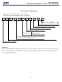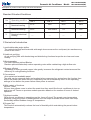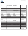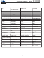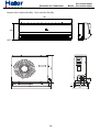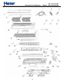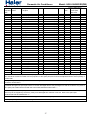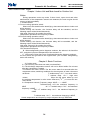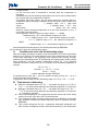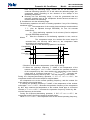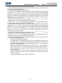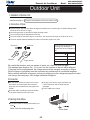
1
Domestic Air Conditioner
SERVICE MANUAL
Models
HSU-12HS03/R2( DB)
HSU-09HS03/R2( DB)
l Features
l
l
l
l
Comfortable:wide-angle airflow
health air purifying
quiet operation
energy efficient
Serial Number: 0010540329
Version:00.00
1
Edition: 2004-10-26
HSU-12HS03/R2(DB)
Domestic Air Conditioner
Model: HSU-09HS03/R2(DB)
Content
1.
2.
3.
4.
Description of product model coding and series introduction--3
Specifications -------------------------------------------------------------6
Curves of performance---------------------------------------------------9
Description,net dimensions and functions of main component s
and accessories------------------------------------------------------------12
5. Knock-down drawings and part lists---------------------------------15
6. Brief introduction to electrical control functions-------------------22
7. Wiring diagram ----------------------------------------------------------38
8. Circuit diagram------------------------------------------------------------ 41
9. Abnormity diagnose-------------------------------------------------------44
10. Trouble shooting------------------------------------------------------------49
11. Refrigerating cycle diagram------------------------------------------51
12. Noise level test chart and air veloc ity distribution-------------------------53
13. Installation manual -----------------------------------------------------56
2
HSU-12HS03/R2(DB)
Domestic Air Conditioner
Model: HSU-09HS03/R2(DB)
DESCRIPTION OF
PRODUCT MODEL CODING
& SERIES INTRODUCTION
3
HSU-12HS03/R2(DB)
Domestic Air Conditioner
Model: HSU-09HS03/R2(DB)
Introductory Remarks
Description of coding rules of unit model
Coding rules and descriptions are as follows:
1
2
3
4
5
6
7
8
9
10
11
Inverter type:(DB),(B)
Refrigerant type:R1(R407C),R2(R410A)
Applicable voltage:3(220~230V),4(240V)
Applicable frequency:0(50HZ),1(60HZ)
Developing sequence :A,B,C,D...
L/C-cooling only
Function code R/H-heat pump
E-electric aided heating
Nominal cooling capacity (BTU/h)with the first two
numbers based on thousand unit
The structure code of indoor & outdoor unit: S(wall-mounted),W(window type),P (cabinet type)
H-Abbreviation of Haier
Examples:
HSU-12H03/R2(DB),It represents wall-mounted split type heat pump DC inverter air conditioner .
The cooling capacity is 12000BTU/h,and the power supply is 220-230V/50Hz, and "R2" means
the refrigerant is R410A.
4
HSU-12HS03/R2(DB)
Domestic Air Conditioner
Model: HSU-09HS03/R2(DB)
Description of product model coding and series introduction
Standard Situation/Conditions
No.
Operating condition
indoor air status
DB C
WBOC
outdoor air status
DB C
WBOC
1
Norminal cooling
27OC
19OC
35OC
24OC
2
Norminal heating
20OC
Not control
7OC
6OC
3
Norminal electrical
heating
---
---
O
---
---
O
C.Series brief introduction
1.comfortable:wide-angle airflow
The vertical dual-flap and horizontal wide-angle louvers ensure the cool(warm) air reaches every
corner of the room.
2.Health air purifying
An air purifying filter with deodorizing and disinfecting functions keeps the air clean and users
healthy.
3.Quiet operation
Fan With Random-pitched Blades.
Random-pitched blades help reduce operating noise while maintaining a high airflow rate.
4.Engergy efficient
The design of inner-grooved copper tube greatly increases the refrigerant contact area and the
efficiency of cooling/heating functions.
5.Convenience
Auto restart and washable panel:
The grille can be removed easily and washed when necessary.Any series have the function then
even if the power falls when the unit is operating unit will automatically return to the operating
settings in use before the power failure when power is restored.
6.Wide variety of functions
24-Hour Timer:
24-hour timer allows users to select the exact time they would like the air conditioner to turn on
and to turn off.Timers on previous models operation based on the number of hours of desired
operation.
7.Night-set models
When the air conditioner is operationg on the timer-off circuit.The preset room temperature
gradually rises(going down in heating)before the unit stops as shown delow.Users can sleep
comfortably without sudden change in temperature.
8.Program”dry”
This function automatically reduces the level of humidity while maintaining the preset indoor
temperature.
5
HSU-12HS03/R2(DB)
Domestic Air Conditioner
Specifications
6
Model: HSU-09HS03/R2(DB)
HSU-12HS03/R2(DB)
Domestic Air Conditioner
Model: HSU-09HS03/R2(DB)
Specification:
Model:
(HSU-12HS03/R2(DB))
Appearance color
(indoor/outdoor):
Cooling capacity:
3440(460-3920)W
Heating capacity:
3820(700-5100)W
Cooling coefficient:
Cooling power input:
Moisture removal
3.21
1070(185-1420)W
1.5X10⁻³m3/h
Heating coefficient:
Heating power input:
Frequency range
3.00
1270(666-1520)W
12~120 Hz
Operating voltage range
1PH, 220-230V~,50Hz
Refrigerant type
R410A
Operating temp. range
-7 C-43 C
Air sending angle/distance
60
Variation of temp. adjust
O
O
+1 C
O
Fan type/quantity
White/White
O
Cross flow fan(indoor unit)
Axial fan(outdoor unit)
Climate type:
T1
Class of electric shock protection:
I
Indoor unit noise
(cooling)
42/38/35dB(A)
outdoor unit noise
(cooling)
56/48dB(A)
Indoor unit noise
(heating)
42/38/35dB(A)
outdoor unit noise
(heating)
58/48dB(A)
net dimensions
760x182x285mm
net dimensions
780 x245x540mm
Packaging dimensions
(indoor unit)
837 x282x312 mm
Packaging dimensions
(outdoor unit)
908x342x619mm
weight(indoor unit )
8.6/10.8(net/gross)kg
Piling layers for indoor/outdoor
unit
8/4
Max. mounting height
difference:
15m
Outdoor unit net/gross weights:
33/36(net/gross) kg
Refrigerant charge
R410A 940g
Current entering side
(indoor/outdoor)
indoor
Max. refrigerant charge
-------------
Frequency of filter cleaning Once/2 weeks
Compressor model
C-6RZ092H1A
Compressor manufacturer
SANYO
Compressor oil charge
320ml
Compressor protector type
INTERNAL
Maxi. length of connecting
pipe:
Cap. tube type muffle
model:
15m
model of 4-way valve:
-------------
TP2Y copper tube
Length/diameter of drain hose
2000mm/O16mm
Type/size of evaporator and
condenser
Max. operating pressure at cool
side:
Internal treaded pipe
O7/O7mm
Appearance features
Indoor unit:Plastic
Outdoor unit: Metal
Fan speed: (r/min)
1300(h)/1250(c)1100/950 (indoor)
800/500 (outdoor)
Max. operating pressure at
warm side:
4.15MPa
cut-off valve:
1/4”,1/2”
7
4.15MPa
HSU-12HS03/R2(DB)
Domestic Air Conditioner
Specification:
Model:
(HSU-09HS03/R2(DB))
Model: HSU-10HS03/R2(DB)
Appearance color
(indoor/outdoor):
White/White
Cooling capacity:
2700(950-3400)W
Heating capacity:
3300(1000-4200)W
Cooling coefficient:
Cooling power input:
Moisture removal
3.21
840(300-1150)W
1.2X10⁻³m3/h
Heating coefficient:
Heating power input:
Frequency range
3.44
960(450-1300)W
12~120 Hz
Operating voltage range
1PH, 220-230V~,50Hz
Refrigerant type
R410A
Operating temp. range
-7 C-43 C
Air sending angle/distance
60
Variation of temp. adjust
O
O
+1 C
O
Fan type/quantity
O
Cross flow fan(indoor unit)
Axial fan(outdoor unit)
Climate type:
T1
Class of electric shock protection:
I
Indoor unit noise
(cooling)
38/37/30dB(A)
outdoor unit noise
(cooling)
54dB(A)
Indoor unit noise
(heating)
39/36/32dB(A)
outdoor unit noise
(heating)
55dB(A)
net dimensions
760x285x182mm
net dimensions
780 x245x540mm
Packaging dimensions
(indoor unit)
837 x282x312 mm
Packaging dimensions
(outdoor unit)
790x366x484 mm
weight(indoor unit )
8.6/10.8(net/gross)kg
Piling layers for indoor/outdoor
unit
8/4
Max. mounting height
difference:
15m
Outdoor unit net/gross weights:
31/34(net/gross) kg
Refrigerant charge
R410A 640g
Current entering side
(indoor/outdoor)
indoor
Max. refrigerant charge
-------------
Frequency of filter cleaning Once/2 weeks
Compressor model
DA89X1C-20FZ
Compressor manufacturer
TOSHIBA
Compressor oil charge
370ml
Compressor protector type
INTERNAL
Maxi. length of connecting
pipe:
Cap. tube type muffle
model:
15m
model of 4-way valve:
-------------
TP2Y copper tube
Length/diameter of drain hose
2000mm/O16mm
Type/size of evaporator and
condenser
Max. operating pressure at cool
side:
Internal treaded pipe
O7/O7mm
Appearance features
Indoor unit:Plastic
Outdoor unit: Metal
Fan speed: (r/min)
1250/950/730 (indoor)
730 (outdoor)
Max. operating pressure at
warm side:
4.15MPa
cut-off valve:
1/4”,3/8”
8
4.15MPa
HSU-12HS03/R2(DB)
Domestic Air Conditioner
Model: HSU-09HS03/R2(DB)
Curves of performance of compressor
9
HSU-12HS03/R2(DB)
Domestic Air Conditioner
Model: HSU-09HS03/R2(DB)
Curves of compressor performance
DA89X1C-20FZ
Compressor:DA89XIC-20FZ
Model:HSU-09HS03/R2(DB)
SUCTION GAS TEMP OC
35
UNDER COOL OC
8.3
Ambient temp OC
35
60.0
60.0
55.0
50.0
45.0
5.5
4.5
3.5
2.5
input (W)
1200
1000
60.0
800
55.0
50.0
45.0
capacity (W)
600
4000
45.0
50.0
55.0
60.0
3500
3000
2500
2000
1500
1000
500
-5
5
-0
evaporating temp C
O
10
10
Condensing temp OC
curent (A)
6.5
HSU-12HS03/R2(DB)
Domestic Air Conditioner
Model: HSU-09HS03/R2(DB)
Curves of compressor performance
Model:HSU-12HS03/R2(DB)
COMPRESSOR:C-6RZ092H1A
SERIAL NUMBER
FREQUENCY
INPUT POWER
1
30
1244
2
50
2321
3
60
2833
4
80
3983
5
90
4502
6
110
5565
7
120
6246
COOLING CAPACITY
7000
6000
5000
4000
3000
2000
1000
0
1
2
3
4
5
6
7
COOLING CAPACITY
SERIAL NUMBER
FREQUENCY
INPUT POWER
1
30
387
2
50
570
3
60
691
4
80
973
5
90
1109
6
110
1465
7
120
1605
INPUT POWER
1800
1600
1400
1200
1000
800
600
400
200
0
1
2
3
4
5
6
7
INPUT POWER
11
Domestic Air Conditioner
Model:
HSU-12HS03/R2(DB)
HSU-09HS03/R2(DB)
Description,dimension and function of
main components and accessories
12
HSU-12HS03/R2(DB)
Domestic Air Conditioner
Model: HSU-09HS03/R2(DB)
Outdoor unit
INLET
CONNECTING PIPING AND ELECTRICAL WIRING
OUTLET
DRAIN HOSE
13
HSU-12HS03/R2(DB)
Domestic Air Conditioner
Model: HSU-09HS03/R2(DB)
NE T DIME NSIONS FOR INDOOR UNIT
Models: HSU-12HS03/ R2(DB) HSU-09HS03/R2(DB)
760
Fr esh air conditioner
285
68
540
NE T DIME NSIONS FOR OUT DOOR UNIT
140
500
780
62
845
15
123
55
256
286
14
67
Domestic Air Conditioner
Model: HSU-12HS03/R2(DB)
HSU-09HS03/R2(DB)
Knock-down drawings
15
HSU-12HS03/R2(DB)
Domestic Air Conditioner
16
Model: HSU-09HS03/R2(DB)
Domestic Air Conditioner
No. in
exploded
view
1
2
3
4
5
6
7
8
9
10
11
12
13
14
15
16
17
18
19
20
21
22
23
24
25
26
27
28
29
30
31
32
33
Spare parts
number
Spare parts description QTY. Model
in english
001A1434039
0010803981
0010402394
001A1433307
001A4600001
0010600115
0010203320
0010203390
0010201841
0010202788
0010202643
0010201857
0010403014
0010704804
0010801543
0010202133
0010401985
0010805655
0010201995
0010201858
0010401869
0010201852
0010201853
0010201860
0010202791
0010202792
0010802568
0010401823
--------0010101274
0010403518
0010201851
001A4000161
Drain hose
Air purifying
Remote controller
Guarding ring
Battery
Screw assembly
Inlet grille
Decorate panel
Air filter
Front panel
Display panel fixation 1
Display panel fixation 2
Display panel
Evaporator assy.
Bearing
Cross flow fan
Negative ion generator
Drain pan assy.
Wiring clip
Piping support
Stepping motor
Electric box cover I
Electric box cover II
Cover for fan motor
Louver 1
Louver 2
Frame assy.
Fan motor
Fix board
Mounting plate
PCB
Electric box
Terminal block
1
1
1
1
2
1
1
1
2
1
1
1
1
1
1
1
1
1
1
1
1
1
1
1
1
1
1
1
1
1
1
1
Model: HSU-09HS03/R2(DB)
Edition:2004/10/26
Price list Failure The proportion remark
rate
of the spare
part stock
HSU-09HS03/R2(DB)
HSU-09HS03/R2(DB)
HSU-09HS03/R2(DB)
HSU-09HS03/R2(DB)
HSU-09HS03/R2(DB)
HSU-09HS03/R2(DB)
HSU-09HS03/R2(DB)
HSU-09HS03/R2(DB)
HSU-09HS03/R2(DB)
HSU-09HS03/R2(DB)
HSU-09HS03/R2(DB)
HSU-09HS03/R2(DB)
HSU-09HS03/R2(DB)
HSU-09HS03/R2(DB)
HSU-09HS03/R2(DB)
HSU-09HS03/R2(DB)
HSU-09HS03/R2(DB)
HSU-09HS03/R2(DB)
HSU-09HS03/R2(DB)
HSU-09HS03/R2(DB)
HSU-09HS03/R2(DB)
HSU-09HS03/R2(DB)
HSU-09HS03/R2(DB)
HSU-09HS03/R2(DB)
HSU-09HS03/R2(DB)
HSU-09HS03/R2(DB)
HSU-09HS03/R2(DB)
HSU-09HS03/R2(DB)
HSU-09HS03/R2(DB)
HSU-09HS03/R2(DB)
HSU-09HS03/R2(DB)
HSU-09HS03/R2(DB)
HSU-09HS03/R2(DB)
1,The failer rate and the proportion of the spare-part stock are regarded as the reference of the stock for spare-parts;The first
time should be stocked accroded with the proportion of the spare-parts,and it should be adjusted with the actual quantity 3
months later.
2,easy-damaged;The spare-part which is often damaged and the customer must stock in the spare-parts warehouse,and
should be marked with"*"
3,possible damaged:The spare-part which is not often damaged like the easy damaged one and the customer may stock in
the spare-part warehouse accord with the actual case,should be marked with " ".
4,not need provided :The spare-part which is seldom damaged or the maintenance man could not maitmains.The spare
parts may be air freighted by the factory if they were damaged.The customer nees not stock in the spare-part
warehouse,should be marked with " x ".
5,Above should be improved accord with the reply of the market half a year per time.
6.The spare parts price on net is FOB Qingdao term.
17
Domestic Air Conditioner
No. in
exploded
view
1
2
3
4
5
6
7
8
9
10
11
12
13
14
15
16
17
18
19
20
21
22
23
24
25
26
27
28
29
30
31
32
33
Spare parts
number
Spare parts description QTY. Model
in english
001A1434039
0010803981
0010402394
001A1433307
001A4600001
0010600115
0010202789
0010203135
0010201841
0010202788
0010202643
0010201857
0010403014
0010705102
0010801543
0010202133
0010401985
0010805655
0010201995
0010201858
0010401869
0010201852
0010201853
0010201860
0010202791
0010202792
0010802568
0010401823
--------0010101274
0010403518
0010201851
001A4000161
Drain hose
Air purifying
Remote controller
Guarding ring
Battery
Screw assembly
Inlet grille
Decorate panel
Air filter
Front panel
Display panel fixation 1
Display panel fixation 2
Display panel
Evaporator assy.
Bearing
Cross flow fan
Negative ion generator
Drain pan assy.
Wiring clip
Piping support
Stepping motor
Electric box cover I
Electric box cover II
Cover for fan motor
Louver 1
Louver 2
Frame assy.
Fan motor
Fix board
Mounting plate
PCB
Electric box
Terminal block
1
1
1
1
2
1
1
1
2
1
1
1
1
1
1
1
1
1
1
1
1
1
1
1
1
1
1
1
1
1
1
1
Model: HSU-12HS03/R2(DB)
Edition:2004/10/26
Price list Failur The proportion remark
e rate of the spare
part stock
HSU-12HS03/R2(DB)
HSU-12HS03/R2(DB)
HSU-12HS03/R2(DB)
HSU-12HS03/R2(DB)
HSU-12HS03/R2(DB)
HSU-12HS03/R2(DB)
HSU-12HS03/R2(DB)
HSU-12HS03/R2(DB)
HSU-12HS03/R2(DB)
HSU-12HS03/R2(DB)
HSU-12HS03/R2(DB)
HSU-12HS03/R2(DB)
HSU-12HS03/R2(DB)
HSU-12HS03/R2(DB)
HSU-12HS03/R2(DB)
HSU-12HS03/R2(DB)
HSU-12HS03/R2(DB)
HSU-12HS03/R2(DB)
HSU-12HS03/R2(DB)
HSU-12HS03/R2(DB)
HSU-12HS03/R2(DB)
HSU-12HS03/R2(DB)
HSU-12HS03/R2(DB)
HSU-12HS03/R2(DB)
HSU-12HS03/R2(DB)
HSU-12HS03/R2(DB)
HSU-12HS03/R2(DB)
HSU-12HS03/R2(DB)
HSU-12HS03/R2(DB)
HSU-12HS03/R2(DB)
HSU-12HS03/R2(DB)
HSU-12HS03/R2(DB)
HSU-12HS03/R2(DB)
1,The failer rate and the proportion of the spare-part stock are regarded as the reference of the stock for spare-parts;The first
time should be stocked accroded with the proportion of the spare-parts,and it should be adjusted with the actual quantity 3
months later.
2,easy-damaged;The spare-part which is often damaged and the customer must stock in the spare-parts warehouse,and
should be marked with"*"
3,possible damaged:The spare-part which is not often damaged like the easy damaged one and the customer may stock in
the spare-part warehouse accord with the actual case,should be marked with " ".
4,not need provided :The spare-part which is seldom damaged or the maintenance man could not maitmains.The spare parts
may be air freighted by the factory if they were damaged.The customer nees not stock in the spare-part warehouse,should
be marked with " x ".
5,Above should be improved accord with the reply of the market half a year per time.
6.The spare parts price on net is FOB Qingdao term.
18
HSU-12HS03/R2(DB)
Domestic Air Conditioner
Model: HSU-09HS03/R2(DB)
19
22
25 26
1
2
3
4
23
5
7
10
8
24
6
27 28 29
15
16
30
21
20
9
13
18
14
17
11
12
KNOCK-DOWN DRAWINGS FOR OUTDOOR UNIT(HSU-09/12HS03/R2(DB))
19
Domestic Air Conditioner
Model: HSU-09HS03/R2(DB)
Edition:2004/10/26
No. in
explode
d view
1
2
3
4
5
6
Spare parts
number
Spare parts description in english
Model
001A0100017
001A1101009
0010203662
0010403487
0010100419
0010706498
Front grille
Front panel
Fan
Motor
Frame for motor
Heat exchanger
HSU-09HS03/R2(DB)
HSU-09HS03/R2(DB)
HSU-09HS03/R2(DB)
HSU-09HS03/R2(DB)
HSU-09HS03/R2(DB)
HSU-09HS03/R2(DB)
1
1
1
1
1
1
7
001A5736055
Fixed clip
sensor
HSU-09HS03/R2(DB)
1
8
9
10
11
12
13
14
15
16
17
18
19
20
21
22
23
24
25
26
27
28
29
30
001A3800082
0010101388
001A1101010
001A3900056
001A3900055
0010706509
0010706497
0010403022
0010704488
0010705988
0010705255
001A5102050
0010706492
001A17621544
001A1101014
001A1436042
0010804196
001A0100427
0010403365
0010403368
0010403521
0010403520
001A4000105
Temperature sensor
Back panel
Top panel
Compressor temperature sensor
Tube temperature sensor
Entering gas pipe
Capillary Tube
4-way valve coil
4-way valve
Stop valve
Stop valve
Flange Nut
Compressor
Cushion
Bottom plate
Service cover
Separating plate
Reactor box
Reactor
Power Module
PCB
Capacitor board
Terminal Block
HSU-09HS03/R2(DB)
HSU-09HS03/R2(DB)
HSU-09HS03/R2(DB)
HSU-09HS03/R2(DB)
HSU-09HS03/R2(DB)
HSU-09HS03/R2(DB)
HSU-09HS03/R2(DB)
HSU-09HS03/R2(DB)
HSU-09HS03/R2(DB)
HSU-09HS03/R2(DB)
HSU-09HS03/R2(DB)
HSU-09HS03/R2(DB)
HSU-09HS03/R2(DB)
HSU-09HS03/R2(DB)
HSU-09HS03/R2(DB)
HSU-09HS03/R2(DB)
HSU-09HS03/R2(DB)
HSU-09HS03/R2(DB)
HSU-09HS03/R2(DB)
HSU-09HS03/R2(DB)
HSU-09HS03/R2(DB)
HSU-09HS03/R2(DB)
HSU-09HS03/R2(DB)
1
1
1
1
1
1
1
1
1
1
1
3
1
1
1
1
1
1
1
1
1
1
1
forenviroment
temp.
QTY Failure
.
rate
The proportion remark
of the spare part
stock
*
*
*
*
*
*
*
*
*
*
*
1,The failer rate and the proportion of the spare-part stock are regarded as the reference of the stock for spare-parts;The first
time should be stocked accroded with the proportion of the spare-parts,and it should be adjusted with the actual quantity 3
months later.
2,easy-damaged;The spare-part which is often damaged and the customer must stock in the spare-parts warehouse,and
should be marked with"*"
3,possible damaged:The spare-part which is not often damaged like the easy damaged one and the customer may stock in
the spare-part warehouse accord with the actual case,should be marked with " ".
4,not need provided :The spare-part which is seldom damaged or the maintenance man could not maitmains.The spare
parts may be air freighted by the factory if they were damaged.The customer nees not stock in the spare-part
warehouse,should be marked with " x ".
5,Above should be improved accord with the reply of the market half a year per time.
6.The spare parts price on net is FOB Qingdao term.
20
Domestic Air Conditioner
Model: HSU-12HS03/R2(DB)
Edition:2004/09/20
No. in
exploded
view
1
2
3
4
5
6
7
8
9
10
11
12
13
14
15
16
17
18
19
20
21
22
23
24
25
26
27
28
29
30
Spare parts
number
001A0100017
001A1101009
0010203662
0010403508
0010100419
0010706505
001A5736055
001A3800082
0010101388
001A1101010
001A3900056
001A3900055
0010706502
0010706504
001A2500076
0010703501
0010705256
0010705255
001A5102050
0010706499
001A17621544
001A1101014
001A1436042
0010804196
001A0100427
0010403365
0010403368
0010403519
0010403520
001A4000105
Spare parts description in english
Model
QTY Failure The proportion remark
.
rate
of the spare
part stock
Front grille
HSU-12HS03/R2(DB) 1
Front panel
HSU-12HS03/R2(DB) 1
Fan
HSU-12HS03/R2(DB) 1
*
Motor
HSU-12HS03/R2(DB) 1
*
Frame for motor
HSU-12HS03/R2(DB) 1
Heat exchanger
HSU-12HS03/R2(DB) 1
Fixed clip forenviroment temp. sensor HSU-12HS03/R2(DB) 1
Temperature sensor
HSU-12HS03/R2(DB) 1
*
Back panel
HSU-12HS03/R2(DB) 1
Top panel
HSU-12HS03/R2(DB) 1
Compressor temperature sensor
HSU-12HS03/R2(DB) 1
*
Tube temperature sensor
HSU-12HS03/R2(DB) 1
*
Entering gas pipe
HSU-12HS03/R2(DB) 1
Capillary Tube
HSU-12HS03/R2(DB) 1
4-way valve coil
HSU-12HS03/R2(DB) 1
*
4-way valve
HSU-12HS03/R2(DB) 1
Stop valve
HSU-12HS03/R2(DB) 1
Stop valve
HSU-12HS03/R2(DB) 1
Flange Nut
HSU-12HS03/R2(DB) 3
Compressor
HSU-12HS03/R2(DB) 1
*
Cushion
HSU-12HS03/R2(DB) 1
Bottom plate
HSU-12HS03/R2(DB) 1
Service cover
HSU-12HS03/R2(DB) 1
Separating plate
HSU-12HS03/R2(DB) 1
Reactor box
HSU-12HS03/R2(DB) 1
Reactor
HSU-12HS03/R2(DB) 1
*
Power Module
HSU-12HS03/R2(DB) 1
*
PCB
HSU-12HS03/R2(DB) 1
*
Capacitor board
HSU-12HS03/R2(DB) 1
*
Terminal Block
HSU-12HS03/R2(DB) 1
1,The failer rate and the proportion of the spare-part stock are regarded as the reference of the stock for spare-parts;The first
time should be stocked accroded with the proportion of the spare-parts,and it should be adjusted with the actual quantity 3
months later.
2,easy-damaged;The spare-part which is often damaged and the customer must stock in the spare-parts warehouse,and
should be marked with"*"
3,possible damaged:The spare-part which is not often damaged like the easy damaged one and the customer may stock in
the spare-part warehouse accord with the actual case,should be marked with " ".
4,not need provided :The spare-part which is seldom damaged or the maintenance man could not maitmains.The spare
parts may be air freighted by the factory if they were damaged.The customer nees not stock in the spare-part
warehouse,should be marked with " x ".
5,Above should be improved accord with the reply of the market half a year per time.
6.The spare parts price on net is FOB Qingdao term.
21
HSU-12HS03/R2(DB)
Domestic Air Conditioner
Model: HSU-09HS03/R2(DB)
Brief introduction to electrical
control functions
22
HSU-12HS03/R2(DB)
Domestic Air Conditioner
Model: HSU-09HS03/R2(DB)
INDOOR UNIT PART
1. Application Range
This function guide can be used for the HSU-09HS03/R2(DB) air-conditioners and
other frequency-convertings made by Headquarters of
Qingdao Haier
Air-conditioner Co.,Ltd
Indexes in this guide (symblised by parameters) refer to the indexes stored in the
EEPROM. Please refer to the EEPROM index chart.
2. Temperature Ajusting function
. This function will decide the outdoor-set’s running speed according to the
domestic temperature and the set temperature.
. Control the domestic blower fan according to the need for temperature adjusting
when the wind rate is automatic
. Control the domestic blower fan according to the disc-tube temperature when it’s
running for heating.
2.1.1 Indoor environment temperature sensor specification
Under the conditions of short circuit or open circuit, the indicative light will flash an alarm and
the indoor blower fan stops. When it returns to normal condtions, the operation will come
back to normal.
Short circuit
Temperature: over 126℃. Sixteen scales: over F8H. Resistance value: below 0.65 K.
Voltage: over 4.85 V
Normal temperature
Temperature: 25 ℃. Sixteen scale: 40H Resistance value: 23K . Voltage: 2.33 V
Disconnection
Temperature : below minus 31 ℃. Sixteen scale: belo w 08H . Resistance value:
below 620K. Voltage: below 0.15 V
.B index=4200
R(25℃)=23K
2.1.2 During the time when the heat running starts and indoor blower fan stops or
when the warm boot starts and within 30 seconds after the indoor blower fan starts,
the resistance value for indoor environment temperature sensor will be neglected.
2.2 The frequency kept when the frequency rises.
. When the operation enters into the work mode, in order to insure the full
oil-returning, some frequency should be kept for some time.
Indication time
Indication
frequency
Cooling & moisture
Heating
Heating
Frequency kept
removing
& Frost removing
60 seconds
60 seconds
30 seconds
58 Hz
When the unit is switched on and the forcible running is over, the temperature level
control starts.
2.3 Modify the set temperature
The set temperature can be modified according to the unit’s operation mode, wind
volume or whether it is under forceful running condition.
The modification of wind volume is only limited within the switch between weak
23
HSU-12HS03/R2(DB)
Domestic Air Conditioner
Models: HSU-09HS03/R2(DB)
and medium of wind volume when it is under heating mode.
Modification index table for set temperature
Mode
Heating
Cooling &
moisture
removing
Content of modification
Modified variable
Operation mode modi hp
fication
Forceful operation modification
ETBL0
Weak wind volume
modification
Medium wind volume
modification
Operation mode modification
ETBL2
Forceful operation modification
ETBL5
Modified parameter
ETBL1
ETBL3
ETBL4
2.4 temperature level control
2.4.1 Deviation
Work out the deviation of temperature level as follows:
In heating mode: E=(Remote -control set temperature+ modified value)-room
temperature
In cooling & moisture removing mode: E= room temperature -(Remote-control set
temperature + modified value)
2.4.2 Compressor OFF
E is minus and |E|>ΔT
Heating
Cooling
ΔT
TCHAHL
TCHACL
afterΔT changes
TCHAHH
TCHACH
condition forΔT changes
The compressor stops after 120 seconds of continuous detection
When the operation starts,according to the table above, the unit will operate
according to the after-the-ΔT-change parameters before the compressor stops
for the first time.
From the time the compressor stops to the time it starts again, the operation will
follow the ΔT (except the moisture removing mode)
When the operation starts and the operation modes change (except when the idle
mode is over) and the deviation is bigger than –ΔT, the compressor starts.
When the compressor is working and the remote -controller set temperature falls
below –ΔT, the compressor stops.
2.4.3 Compressor operation
When the compressor is kept idle for 3 minutes, the deviation E will be higher
than -△T+0.67℃ and the compressor will start working.
2.4.4 DASH operation
When the operation starts or the operation mode changes (except when the
compressor is switched on after being off), the compressor is on and the indicated
maximum frequency should be as follows:
24
HSU-12HS03/R2(DB)
Domestic Air Conditioner
Model: HSU-09HS03/R2(DB)
Cooling
deviation to zero
Moisture removing
deviation to level G
Heating
deviation to level F
There will be no DASH operation under trial operation, emergency operation and
silent operation modes.
2.4.5 Temperature adjusting of different levels. (DASH operation conditions under
different modes)
cooling 制冷/ moisture removing 除湿 /heating 制热 /level 区段/ cooling 制冷/
moisture removing 除湿/heating 制热/Value E E 值/<120 seconds/ 3-minute idle
mode 3 分钟待机/compressor resta`1rt 压缩机再启动
2.4.6 Frequencies for different levels
Within different levels, the indicated frequencies are(the frequency the indoor unit
transmits to the outdoor unit) as follows;
Under the cooling & moisture-removing mode, level A and B have the same
frequency.
Under the silent mode, levels A-E have the same frequency with level F
Indicated frequency
Heating
Silent
heating
Moisture
removing
Cooling
Silent
cooling
FQHOT [0—7]
FQSHOT [0—2]
Frequency
range
Temperature
change level
A—H
F—H
FQDRY [0—7]
B—H
FQCOOL [0—7]
FQSCOOL [0—2]
B—H
F—H
25
HSU-12HS03/R2(DB)
Domestic Air Conditioner
Model: HSU-09HS03/R2(DB)
The maximum frequency value refers to the max value listed above.
The maximum and minimum values for cooling and heating are the maximum and
minimum values for correspondent items.
2.4.7 Controlled frequency for the same level
The indicated frequency when a level remains unchanged after the compressor
operates with the same frequency for 3 minutes.
The timing will start again when there is a different frequency input. If the
temperature level remains unchanged for 3 minutes, the indicated frequency will
change again (add FQUPH or FQUPL)
Controlling form for the same level
A B
C
Levels of temperature change
D
E
F
G
H
Heating
Cooling
moisture
removing
&
2-4-8. Select the wind volume when it is set automatic
When the wind volume is automatic, it can be switched between strong, medium
and weak according to the temperature adjusting levels.
Wind volume under the automatic wind volume mode
Heating
cooling
Moisture
removing
A
Str
on
g
B
Stro
ng
Temperature adjusting levels
C
D
E
F
G
Stro Stro Stron Med Wea
ng
ng
g
ium k
Stro
ng
Stro
ng
Stro
ng
Med
ium
Stro
ng
Med
ium
Medi
um
Medi
um
Med
ium
Wea
k
Wea
k
Wea
k
H
I
Wea SLO
k
Wea Weak
k
SLO SLO
2-5. Frost removing
Under the intensive-running protection mode, the protection control will be in
priority
The compressor does not stop
Under heating operation mode, the outdoor unit sends a frost-removing signal
(I21=10) and the indoor unit will start the frost-removing control until the outdoor
unit transmits the signal to end the frost-removing. Then the indoor unit starts the
heating operation, indication levels and wind volume control will operate following
the heating temperature levels.
2-6. Wind volume limit
. When the compressor is working and the max setting for indoor blower fan is
medium , the upper limit of indicated frequency is as follows:
26
HSU-12HS03/R2(DB)
Domestic Air Conditioner
Model: HSU-09HS03/R2(DB)
Frequency control form for wind volume
Limited frequency
Limited frequency
variables
Medium wind volume
FQLIMMD
Weak wind volume
FQLIMLO
When judging the conditions for frequency limit under the heating mode, first
judge if the unit has been set to weak wind volume mode. If it has been set to one
mode, then follow the table below for the limit modification.
Outdoor temperature
Indicated frequency
condition
011 (Below 20℃)
Limited frequency for weak
010(15-20℃)
Limited frequency for weak
001(10-15℃)
Limited frequency for weak
000(below10℃)
Normal frequency
3. Indoor blower fan control
3-0-1. Targeted running speed
Model 09
Running speed variable
Heating
Cooling
Ventilatio
n
Quota
Slightly weak
SSLO silent SSLO
FRPMTBL00
FRPMTBL01
Weak
Strong
Weak
Aut
Strong
oma
tic
Slightly weak
FRPMTBL02
FRPMTBL05
FRPMTBL04
FRPMTBL05
SSLO silentSSLO
Weak
Strong
Weak
Aut
Strong
oma
tic
Weak
FRPMTBL07
FRPMTBL08
FRPMTBL11
FRPMTBL10
Strong
FRPMTBL13
Cooling
Heating
FRPMTBL09
FRPMTBL03
running speed
(rpm)
FRPMTBL06
FRPMTBL11
FRPMTBL12
. When the wind volume is manually medium, the running speed is
(strong+weak)/2.
When it is automatically medium, the running speed is (strong automatic+ weak
automatic)/2(not counted if it is not up to 10rpm)
27
HSU-12HS03/R2(DB)
Domestic Air Conditioner
Model: HSU-09HS03/R2(DB)
3-1.heat running
3-1-1. Warm boot
When the heat running starts or the frost removing ends and the compressor starts
again, in order to avoid cold wind, warm boot wind volume control should be done.
Heat exchange temperature
THHOT3
37.0℃
THHOT2
35.2℃
THHOT1
25.2℃
THHOTR
16℃
4 minutes
Stop slightly weak weak
setting
weak
slightly weak
stop
To control the indoor blower fan as shown in the table above according to the heat
exchange temperature
When the heat exchange temperature rises to the level between THHOT1 and
THHOT2 and even after 4 minutes it cannot reach the level between THHOT2 and
THHOT3, enter into the next level without referring to the heat exchange
temperature.
the blower fan stops when the heat exchange temperature is below 25℃
the blower fan is working slightly weak when he heat exchange temperature is
above 25 ℃ and below 35℃
the blower fan is working weak if the he heat exchange temperature remains 35℃
for less than 4 minutes.
The blower fan works as set if the he heat exchange temperature remains 35℃ for
more than 4 minutes
the blower fan works as set if the he heat exchange temperature remains above
37℃
3-1-2. When the compressor stops and remains idle for 3 minutes
20 seconds after the compressor stops, the wind volume is weak(switching to
SSLO in silent running mode)and then slightly weak.
If the compressor stops when the heat running starts, the wind volume is weak
3-1-3. Restart of the compressor
The wind volume is set by the remote-controler after the warm boot.
.select the wind volume by the temperature in the automatic wind volume mode。
28
HSU-12HS03/R2(DB)
Domestic Air Conditioner
Model: HSU-09HS03/R2(DB)
Refer to the temperature level control function
3-1-4. Frost-removing operation
. The blower stops after 20 seconds
. When receiving the I21=11 signal from the outdoor unit in the heat frost-removing
mode, warm boot will be done according to the hear exchange sensor. The wind
volume control is the same with 3.1.1
When the frost-removing process if over, if the compressor is on,the wind volume
control will be warm-booted; if the compressor if switched off, the wind volume will
be weak.
3-2 cooling running
. The wind volume can be set to strong, medium and weak.
Automatica wind volume function will decide the wind volume according to the
temperature
Picture3.3
3-3. Moisture removing running
3-3-1. Compressor off, idle mode for 3 minutes
. The blower fan stops as the compressor stops
. The operation is wead after 3 minutes’ idle mode
. After 3 minutes’ ilde mode, the compressor is on.
3-3-2. Compressors on
The compressor operates as the set wind volume when the wind volume is set to
be strong, medium or weak
. The wind volume is decided according to the temperature adjusting when the
wind volume is set to be automatic.
Picture 3.4
Moisture removing running
Level H
3minutes idle mode
CompressorOFF
weak
weak
setting
Setting slightly weak OFF
4.Powerful Running
. Powerful running for 15 minutes
. The running stops or ends the powerful running after 15 minutes
. The mode switch ends the powerful running
. Enter into the silent mode, normal running mode or timed switching on mode to
end the powerful running
. When in automatic mode, there are powerful and silent functions for your choice.
When the main unit is in cooling mode, it operates with powerful cooling or silent
cooling. When the main unit is in heating mode, it operates with powerful heating
or silent heathing. When the main unit is in wind-sending mode, there are no
powerful or silent modes.
4-0-1. Powerful heating
29
HSU-12HS03/R2(DB)
Domestic Air Conditioner
Model: HSU-09HS03/R2(DB)
. Change the set temperature. With temperature adjusting function
. The wind volume is the automatic medium
. When in frost removing mode, the outdoor unit does not accept the
communication signal for powerful running
. After 15 minutes of powerful running, the compressor can not be off within 10
minutes
4-0-2. Powerful cooling
Change the set temperature. With temperature adjusting function
. The wind volume is the automatic strong
. After the compressor starts, there will be no low-intense running protection within
3 minutes
4-0-3.There is no powerful mode for wind-sending and moisture removing
5.Silent running
. Send the silent running signal to the outdoor unit
5-0-1. Silent hearing
The wind volume is SSLO after the compressor is on
The wind volume will be kept SSLO within 20 seconds after the compressor stops
and then changes to weak
5-0-2. Silent cooling
The wind volume is SSLO
5-0-3. There is no silent mode for moisture removing and wind-sending.
6. Timed running
. Set the time duration according to the time difference between the clock for
timing and the current clock
. In timing mode, the display panel will flash the light at fixed times
6-0-1. Timed OFF
When this function is set, operation modes on the panel display will not change.
The timing icon will show and the operation stops when the set time comes.
6-0-2. Timed ON
When this function is on, the panel display will only show a timing icon. The unit
will operate as the set mode when the time comes.
6-0-3. Timed ON/OFF
The unit will start operating or stop according to the order of your setting.
7. Automatic running
7-1. Automatic running mode
Under this mode, the MCU will choose the work mode according to the room
temperature so as to keep the set termperature ( set 23℃ for heating mode and
26℃ for cooling mode)
When the unit is powered on for the first time and the the room termperature is equal to or
below 23℃, it will start the heating mode or the cooling mode when the room temperature is
higher than 23℃
Enter into the heating mode and follow the heating process(supposed temperature 23℃).
When the temperature is high enough to stop the compressor, the compressor stops and there
30
HSU-12HS03/R2(DB)
Domestic Air Conditioner
Model: HSU-09HS03/R2(DB)
will 3 minutes of idle mode. If the compressor senses the incoming wind temperature is higher
than 23℃ after it stops for 15 minutes, the unit will switch to cooling mode. Otherwise it will
keep the heating mode.
Enter into the cooling mode and follow the cooling process( supposed temperature 26℃).
Compensation temperature difference will be cancelled automatically. When the temperature
is high enough to stop the compressor, the compressor stops and there will be 3 minutes for
idle mode. If the compressor senses the incoming wind temperature is equal to or below 23℃
after it stops for 15 minutes, the unit will switch to heating mode. The compensation
temperature will be added automatically. Otherwise it will keep the cooling mode.
When the unit switches from other modes to automatic mode, if the work state changes (judge
first and then work), there will be 3 minutes for idle mode. Ant then the temperature will change
to the judged level according to the incoming wind temperature.
8. Trial running
The indicated frequency for trial running is 58Hz, wind volume is strong.
The trial running will last for 30 minutes and then the unit will be powered off. The
unit will exit the trial running if it receives any remote-control signal during the trial
running period.
There is no low work-intense running protection.
9. Low Work-intense protection control
Specification for heat-exchange termperature sensor
B fixed number=3700 R(25℃)= 10KO
Under the cooling /moisture removing modes,the low work-intense protection will
be carried out according to the heat-exchange temperatures as shown in the table
below.
Low Work-intense protection control
Picture 11.1
Heat-exchange temperature
THLHEATBL3
THLHEATBL2
THLHEATBL1
THLHEATBL0
Indication
level
Normal level2 level 1
stop
level 1
level 2
normal
Low Work-intense protection control will be neglected in the trial running.
Low Work-intense protection control will be cancelled for 3 minutes temporarily
after the powerful cooling starts for 1 minute
(THLH[3 ,2,1,0]= 7℃ ,4.6 ℃,2.2℃,-0.5℃)
10. High Work-intense protection control
Under the heating mode, the high work-intense protection will be carried out
31
HSU-12HS03/R2(DB)
Domestic Air Conditioner
Model: HSU-09HS03/R2(DB)
according to the heat-exchange temperatures as shown in the table below.
High Work-intense protection control:
Picture 12.1
Heat-exchange temperature
frequency values when the high work-intense starts
THHEAT6
74.7
THHEAT5
70.3
THHEAT4
65.1
THHEAT3
62.2
THHEAT2
52.9
THHEAT1
51.6
THHEAT0
47.1
C D
Indicated
frequency
Normal
E
D
C B
idle mode
High Work-intense protection
A
B CD
E
stop
High Work-intense protection
alarm
High Work-intense protection alarm will start if there are two times of high work-intense
protection within 30 minutes.
.
. If the heat-exchange temperature does not reach THHEAT [2], it will resume to
the normal temperature level control
. The smaller one of the high work-intense frequency and level frequency will be
the operation data.
11. Low-temperture treatment for Heating mode
If the four-way valve can not switch or when the none-frost-removing
compressor starts again under the heating mode if the heat-exchange temperature
remains under"THHOTLTH"(-4.5 ℃)for 90 seconds, the compressor will start 3
minutes of idle mode and start again when the heat-exchange temperature is
above " THHOTLTH "(-4.5℃)
12. Remote control
. Start or stop running with the remote-control signals.
. Only OFF signal is accepted when there are emergencies or malfunctions.
1 second delay: Starting, stopping and signals except the wind direction signal all
begins 1 second after the receiption of the signal.
13.EEPROM control
. EEPROM is wrong when the EEPROM parameter sum does not accord with the
check sum after the outdoor unit is powered on.
. The outdoor unit EEPROM is wrong will be displayed when the indoor unit
32
HSU-12HS03/R2(DB)
Domestic Air Conditioner
Model: HSU-09HS03/R2(DB)
receives wrong EEPROM signals from the outdoor unit.
. In this case the control and emergency operation are not allowed.
. Power-off to disarm.
14 .Trouble Records
. There are no lists if there are no error code records.
. The malfunction display will automatically disappear after 10 seconds.
The remote control accepts stop signal only. The malfunction record may end
according to the ON/OFF or remote-control’s stop signal
. Models with EEPROM can store the records when they are replugged to the
power.
15. Special functions
1、The indoor unit operates only
a. To enter into this function please press the sleep key 6 times with 6 beeps in 7 seconds
under the none-power-failure-compensation mode.
b. :The indoor unit operates as follows after entering into the function.
The indoor unit operates and communicates according to the setting without processing the
signals from the outdoor unit but needs to send signals to the outdoor unit without stop.
c. To exit this function please press the OFF key of the remote-controller or the emergency key
to power off the unit. You can also unplug the machine to exit this function.
When the indoor unit operates independently, it imitates the outdoor unit to send the following
signals to the indoor unit.
Output frequency 58 Hz ,error frost removing state: 17654=0001,13=0,121=01 ,external
temperature level K54=00, the indoor heat-exchange temperature is fixed at 47℃
33
HSU-12HS03/R2(DB)
Domestic Air Conditioner
Model: HSU-09HS03/R2(DB)
OUTDOOR UNIT PART
Chapter I: Indoor Unit and Main board for Outdoor Unit
Notice:
During operations under any mode, if short circuit, open circuit and other
malfunctions of the temperature sensors are detected, the main engine should
come to a halt immediately.
1. Outdoor-board:
1.1.Forced cooling operation switch:
Short circuit this switch before electrifying, data communication to indoor unit
will be ignored:
Forced cooling will function, the 3-minute delay will be cancelled, and the
following output will be ON simultaneously:
High wind volume (H) for outdoor fan motor;
Compressor operates at the frequency of 80Hz.
1.2.Forced heating operation switch:
Short circuit this switch before electrifying, data communication to indoor unit
will be ignored:
Forced heating will function, the 3-minute delay will be cancelled, and the
following output will be ON simultaneously:
High wind volume (H) for outdoor fan motor;
Compressor operates at the frequency of 80Hz.
CPU checks all A/D ports
B.When safeguarding action happens outdoors, the actions in A should be
OFF, and other inputs are independent of the actions in A.
C.LED output: Goes along even if safeguarding action happens outdoors;
Cut this switch and go back to the original state. (The out-door safeguarding
action will continue)
Chapter II: Basic Functions
3. Cooling mode
3.1.The four-way valve does not work (not electrified)
3.2.The discharge temperature sensor will not be tested within five minutes
after the compressor is started
3.3.Outdoor fan motor control: The fan motor starts five seconds after the
compressor starts, switching conditions for the two gears of wind volume are
as follows:
T ambient temp. <21℃, Low wind volume
T ambient temp. >21 ℃ , High wind
volume
When the fan motor starts up, and
the ambient temperature is at the return difference (±2℃), it runs at the low
wind volume.
3.4.Compressor control: Frequency range: 30HZ---------120HZ
T ambient temp. <16℃, the maximum frequency is
65HZ
16℃≤T ambient temp.≤30℃,the maximum
frequency is 90HZ
30℃≤T ambient temp.≤41℃,the maximum frequency is
110HZ
T ambient temp.≥41℃,the maximum frequency is 85HZ
Actual temperature and frequency maybe adjusted through EEPROM
34
HSU-12HS03/R2(DB)
Domestic Air Conditioner
Model: HSU-09HS03/R2(DB)
4.Heating mode
4.1.The four-way valve is electrified 2 seconds after the compressor is
electrified
4.2.Malfunctions of the discharge temperature sensor will not be tested within
five minutes after the compressor is started
4.3.Outdoor fan motor control: The fan motor starts five seconds after the
compressor starts, switching conditions for the two gears of wind volume are
as follows:
T ambient temp. <16 ℃ , High wind
volume
T ambient temp. ≥ 16 ℃ , Low
wind volume
When the fan motor
starts up, and the ambient temperature is at the return difference (±2℃), it
runs at the low wind volume.
4.4.Compressor control: Frequency range: 30HZ---------120HZ
T ambient temp. >22℃, the maximum frequency is 70HZ
9℃≤T ambient temp.≤22℃,the maximum frequency is 90HZ
2 ℃ ≤ T ambient temp. ≤ 9 ℃, the maximum frequency is
100HZ
T ambient temp. <2℃,the maximum frequency is 110HZ
Actual temperature and frequency can be adjusted through EEPROM
4.5.Conditions to enter into the defrosting stage:
A.
Conditions to enter into the defrosting stage
After the heating operation has begun, and the operation time of the compressor
adds up to 45 minutes (The total operation time of the compressor will be reset
to zero after defrosting or the operating mode switched into cooling), through
examining the defrosting sensor TE (Examining the frosting status of the outdoor
heat exchanger) and the ambient temperature sensor TA, if the following
conditions are met continuously up to 5 minutes, then defrosting operation is
entered:
TE≤C×TA-α
Of which:C:TA<0℃,C=0.8
TA≥0℃,C=0.3
α maybe adjusted through EEPROM
For places easy to frost, set α as H; For places not easy to frost, set α as L; It
is set as M when leaving factory.
Temperature limit to enter into the defrosting stage -15℃E≤C×TA-α≤2℃E
B.Time interval of defrosting
While the calculated data of C×TA-α fall within the range of -15℃E≤C
×TA-α, the time interval between two defrosting operation is 45 minutes
l While the calculated data of C×TA-α fall within the range of C×TA-α
≤-15℃E, the time interval between two defrosting operation is 55 minutes
C.Defrosting operation
l When defrosting begins, the compressor and the outdoor fan motor stops,
and the four-way valve turns OFF 50 seconds later.
l The compressor starts and stays at the frequency of 60HZ for 30 seconds,
then operates towards the target frequency (Can be adjusted through
EEPROM)
l The current safeguard and the compressor discharge safeguard and
other means of safeguard remain valid while defrosting. If the compressor
l
35
HSU-12HS03/R2(DB)
Domestic Air Conditioner
Model: HSU-09HS03/R2(DB)
halts during the defrosting stage, remain still for 30 seconds, then
conducts defrosting operation if it is still within the defrosting stage, the
compressor starts according to the demand of the startup of the
defrosting compressor.
l Entering into the defrosting stage, it must be guaranteed that the
minimum operation time of the compressor should amount at least to 2
minutes before exit defrosting.
D. Conditions to exit the defrosting stage
The defrosting operation will return to heating operation if any of the following
conditions is met.
(1):The temperature of the outdoor heat exchanger remains above
7 ℃ (Can be adjusted through EEPROM) for over 80 seconds
continuously.
( 2 ): Keep defrosting operation for 9 minutes (Can be adjusted
through EEPROM) continuously.
E . After the condition to exit defrosting operation is met, work as
follows.
The compressor stops, the outdoor fan motor stops 50
seconds later, the four-way valve turns on, the compressor starts
according to the starting process.
Time sequence of the defrosting operation is as follows:
Compressor
Outdoors fan motor
Four-way valve
60×9Max
5.Outdoor condensation temperature control while cooling:
5.1.When the operation frequency F < 40HZ, if the temperature of the
outdoor coiled pipe T outdoor coil≥52℃, decrease the operation frequency
of the compressor by 2Hz,then examine the temperature of the outdoor
coiled pipe at 10-second intervals, if T outdoor coil ≥ 52 ℃ , decrease the
operation frequency further by 2Hz, until the frequency is the lowest;
During the frequency-decreasing operation, if 47 ℃ ≤ T outdoor coil < 52 ℃ , the
compressor and the fan motor keep their original states;
the compressor runs at the normal operating frequency, and the outdoor fan
motor returns to its original state,
5.2.When the operation frequency F≥40HZ, if the temperature of the outdoor
coiled pipe T outdoor coil≥57℃, decrease the operation frequency of the compressor
by 2Hz,then examine the temperature of the outdoor coiled pipe at 10-second
intervals, if T outdoor coil≥57℃, decrease the operation frequency further by 2Hz,
until the frequency is the lowest;
During the frequency-decreasing operation, if 52℃≤ T outdoor coil < 57 ℃ , the
compressor and the fan motor keep their original states;
When T outdoor coil≤51℃, the compressor runs at the normal operating frequency,
36
HSU-12HS03/R2(DB)
Domestic Air Conditioner
Model: HSU-09HS03/R2(DB)
and the outdoor fan motor returns to its original state;
The above temperature points, frequency-decreasing step and time interval can
all be adjusted through EEPROM
III. Anti over-loading operation while heating:
5.3.When the operation frequency F<40HZ, if the temperature of the outdoor
coiled pipe T outdoor coil≥52℃, the outdoor fan motor performs forced high-speed
operation and the operation frequency of the compressor should be decreased by
2Hz , then examine the temperature of the outdoor coiled pipe at 10-second
intervals, if T outdoor coil≥52℃, decrease the operation frequency further by 2Hz,
until the frequency is the lowest;
During the frequency-decreasing operation, if 47℃≤ T outdoor coil < 52 ℃ , the
compressor and the fan motor keep their original states;
When T outdoor coil≤46℃, the compressor runs at the normal operating frequency,
and the outdoor fan motor returns to its original state;
5.4.When the operation frequency F≥40HZ, if the temperature of the outdoor
coiled pipe T outdoor coil≥57℃, the outdoor fan motor performs forced high-speed
operation and the operation frequency of the compressor should be decreased by
2Hz , then examine the temperature of the outdoor coiled pipe at 10-second
intervals, if T outdoor coil≥57℃, decrease the operation frequency further by 2Hz,
until the frequency is the lowest;
During the frequency-decreasing operation, if 52℃≤ T outdoor coil < 52 ℃ , the
compressor and the fan motor keep their original states
When T outdoor coil≤51℃, the compressor runs at the normal operating frequency,
and the outdoor fan motor returns to its original state;
The above temperature points, frequency-decreasing step and time interval can
all be adjusted through EEPROM
6.. Compressor discharge safeguard:
5 minutes after the compressor starts, when the compressor temperature
rises above 105℃, decrease the compressor frequency by 2HZ/stop for 10
seconds, until the compressor temperature falls below 90℃, the compressor
returns to normal operation;
When the compressor temperature rises above 115 ℃ , the compressor
should stop at once, wait until the compressor temperature falls below 90℃
and the waiting time period exceeds 3 minutes, the compressor returns to
normal operation;
After the compressor restarts, if the compressor temperature rises above
115℃ once more within 15 minutes, the compressor should stop at once
and give an alarm.
The temperature points are stored in EEPROM
37
HSU-12HS03/R2(DB)
Domestic Air Conditioner
Wiring diagram
38
Model: HSU-09HS03/R2(DB)
HSU-12HS03/R2(DB)
Domestic Air Conditioner
Model: HSU-09HS03/R2(DB)
INDOOR UNIT DIAGRAM
0010552145
FAN MOTOR
POWER SUPPLY
NOTES THE PARTS OF DOTTED 1 , 2 AND 3
ARE OPTIONAL
THE UNIT WITHOUT THE HEALTH FUNCTION
HAS NOT 2
39
B BLACK
BL BLUE
BR BROWN
R RED
W WHITE
Y/G YELLOW/GREEN
HSU-12HS03/R2(DB)
Domestic Air Conditioner
Model: HSU-09HS03/R2(DB)
WIRING DIAGRAM OF OUTDOOR UNIT
WARNING
CAUTION
COMPRESSOR
DON'T TOUCH CAPACITOR, EVEN AFTER
PLUG-OFF ( DANGER OF ELECTRIC
SHOCK)
SPDU
CN10
INDUCTANCE
BL
OR
The capacitor retains high voltage even after
the plug-off. For your safety, be sure to wait at
least 5 minutes. after plug off and use a tester
to confirm the voltage between connector CN1
and CN2 is less than DC 10V before start
servicing.
4-WAY VALVE
1
CN9
AMBIENT TEMP.SENSOR
CN10
TEMP.SENSOR OF HEAT
CN11
COMP.TEMP.SENSOR
FAN MOTOR
20A/250VAC
2
FUSE
FAN MOTOR
B BLACK
R RED
OR ORANGE
BL BLUE
W WHITE
GR GRAY
Y/G YELLOW
/GREEN
FAN MOTOR ① IS FOR“9000BTU”UNITS;
TERMINAL
BLOCK
CAPACITOR PCB BOARD
TO INDOOR UNIT
40
FAN MOTOR ② IS FOR“12000BTU”UNITS;
Domestic Air Conditioner
Model:
CIRCUIT DIAGRAM
41
HSU-12HS03/R2(DB)
HSU-09HS03/R2(DB)
Domestic Air Conditioner
HSU-12HS03/R2( DB)
Model:HSU-09HS03/R2( DB)
INDOOR UNIT
3
Q7
S9013
1
2
3
Q6
S9013
BUZ1
104/50V
R27 10K
2
1
CN9
R30
10K
8
2
Q5
2SC2412
Q4
2SC2412
D14
IC7
D11 1N4007
+5
7805
3
D9
D12
E10
2200U/25V
2SC2412
C34
E15
C35
104
470U/25V
104
R18
4.7k
C17
CON12
ZE1
C40
C12
102
E4
S14K350
104/275V
CON13
FUSE1
220U/16V
C28
C46
104
104
+12V
E12
C11
104
1
T3.15A
10K
+5V
+5V
220V-N
220VL
+5
48
R 3 1K
应急开关
49
R42 10K
R29 10K
D 2 RLS4148
08
C1
102
C
03
E1
1UF/16V
21
C13
104
45
56
60
10
C2 104
C43
103
CN6
C16
102
220V-N
网络(红)
15
2UF 450V
1
2
3
+5V
Q3
220V-L
C39
CN13
RC1
IC10
R4
R38
R39
R40
2SC2412
+5
+12V
16
17
18
23
10K 2 4
R64
R93
RST
C41
102
复位脚
VSS
GND
AVSS/VRE
GND
VSSA
GND
PTC0
PTF7
应急开关
PTC1
遥控接收PTF0/TACH2
运行灯 PTC2/MCLK
制冷灯 PTD7
除湿灯 PTD6/TACLK
制热灯 PTD5
定时灯 PTC3
健康灯 PTC5
晶振 OSC1
+5
TLP3526
R19 4.7K
R20 22K
CGMXFC
NC
R1
1M
空
R73
4.7K
Q13
SW3
5v
Q12
+5v
XT1
C4
8M
104
55
54
20
右摆A
右摆B
右摆C
右摆D
左摆A
左摆B
左摆C
PA0 (单、冷暖) 上 摆 A
C
D
R48 22K A
B
C
D
R89 22K D
28
29
30
31
32
33
38
PA1 (面板选择1)上 摆 B
PA2
上摆C
PA3 (面板选择2)上 摆 D
PA4 (大、小机型)
下摆A
PA5
下摆B
PA6
下摆C
PA7
下摆D
PTB4
左摆D
50
PTD4
PTD3
PTD2
PTD1
PTD0
PTB7/ATD7
PTD6/ATD6
PTB5/ATD5
缩时/自检
PTC4
C19
104
+5V
4.7UF/50V
E6
4.7UF/50V
47
46
43
42
41
40
39
01
RED
Q14
BLU
Q15
16
15
14
13
12
11
10
9
R92
10K
Q16
C
POW
TIM
RED
GRN
BLU
CN5-1
面板
330 1/4W
Q9
2SC2412
+5
6
1
七彩K系列
330K 1/4W
5
2
D4
4
R80
IC14
TLP371
2.2k 1/4W
4
IC12
1N4007
D3
1
CN5
1N4007
+5
1
103/50V C49 R83
2
TLP521
B
N
2.2K
LED1
R84 6.8K 2W
+5V
GREEN
R7 10K
IC2
R8 10K
5v
1
2
3
4
5
6
7
8
9
10
+5V
R 6 9 330
R 8 8 220
R 6 8 220
R81
R82
C7
5 SDA
6
7 SCL
8 24C01A
C14
104
4
3
2
1
R25
22K
ZJ1
IC5
C20
104
2003
CON14(红)
+12
+12
1
FLZ对接线
1
2
D1
RLS4148
门开关
1
2
3
4
5
6
7
8
9
10
负离子
CN3
CN4
RL5
JQ1A-12V
CON15(白)
1
FLZ对接线
左摆步进 右摆步进
编 制:
3
102/50V
+5
C6
CN10
R32 1K
上摆步进电机
下摆步进电机
2
GRN
R77 4.7K
62
SW2
+5v
C21
102
1
C26
O3
RUN
REC
2SB1197
R76 4.7K
63
3
R26
4.7K
C27
102/50V
51
RED
GRN
BLU
R87
1K
103/50V
102/50V
+5V
2SB1197
R74 4.7K
+5
R46
C15
102
C25
52
(白)
CN5-2
A
B
C
D
A
B
C
+5
C32
53
REC
+5V
2SB1197
64
10K 1/4W
门开关
R33 10K
+12
CN2
3.3K 1%
E7
HG系列六指示灯
C3
103
R24
10K
MC68HC908AB32
+12
0010403517变频原理图
C31
102/50V
62
R43 330
C22
R85 2.2K 1/4W
102 R86 10K 1/4W
室外通信接收
自检/缩时
PTB0/ATD0 3 4
IC4
R35
EE时钟 PTF2/TBCH2 06
EE数据 PTF1/TACH3 05
电源 VDDAREF
44
27
2003
A
PTE7/SPSCK
PTG2/KBD2
PTE3/TACH1 PG输出
PTE4/SS
PTE5/MISO 负离子
PTG0/KBD0
PTG1/KBD1
20K 1%
+ 5 B9B-PH-A
1
REC REC
R53 1K
2
3
RUN
R88 220
4
POW
COOL
R70 330
5
DRY
R71 330 RUN
O 3 HEAT 6
R72 330
7
TIM
R68 220
8
HEALTH
R69 330
9
PTE6/MOSI 19 室外通信发送
26
4.7K
2SC2412
电源
B
1
2
3
4
5
6
7
8
R91
2SC2412
网络输出
网络输入
OSC2
VREFH
VDDA
PTE2/TACH0 PG反馈
A
Q10
负离子
PTE0/TXD
PTE1/RXD
晶振
R21 4.7K
R22 22K
2SC2412
61
04
62
53
52
51
63
64
59
R34 R44 1K
C9
102
+5
35 PTB1/ATD1
10K
680
0.01U*120/300V
25
10K
4.7K
10K
4.7K
R57
内风机
C10
102
58
13
14
+5V
B
36
37
PTF4/TBCH0 蜂鸣器2
R36 1K
4
3
2
1
R14 1K
风机反馈
09
+5V
R37 10K
+5V
R50 51K
+5
1
2
3
CN7
57
PTH1/KBD4 集中输出
C30
63
1
2
3
4
5
6
7
8
R10 10K
内环温 PTB2/ATD2
内盘管 PTB3/ATD3
1
室温 2
盘管
3
4
R45 1K
16
15
14
13
12
11
10
9
+5
PTH1/KBD3 集中输入
64
103/50V
CN8
+5
5
4
3
2
1
R 2 10K
+5V
紫外线控
制A
紫外线控
制C
PTF5
PTF6
C38
102/50V
E5
100u/25v
5
4
3
2
1
SW1
C18
104/50V
103/50V
11
12
61
22
1
PTF3/TBCH3 蜂鸣器
VDD
104/50V
07
电源
1
C5 102
Q2
2SC2412
4.7K
过零检测
2
R9
IRQ
3
R28 1K
02
2
1
R41 1K
D
E13
100u/25v
103/50v
R59
4.7K
R31
7
100U/25V
+12V
D13
LB2271
Q11
Q1
2SC2412
R66 2 7
集中
T1
TRAN1-3
LX1
R17
10k
R49
100
1K
+5
远程通信
10K
103/50V
R13
10k
R16
10k
1
C44
R12 1K
D
6
R11
103/50V
C42
5
R65
+5
C29
104/50v R15
10k
+12v
C45
CN12
4
+5
BEEP-PKM13EPY-4002
4
A
12V
C
2
+12v
220V-N
1
紫外线控制
4
5
42
6
7
审 核:
8
A
HSU-12HS03/R2(DB)
Domestic Air Conditioner
OUTDOOR UNIT:
43
Model: HSU-09HS03/R2(DB)
HSU-12HS03/R2(DB)
Domestic Air Conditioner
Model: HSU-09HS03/R2(DB)
ABNORMITY DIAGNOSE
44
HSU-12HS03/R2(DB)
Domestic Air Conditioner
Model: HSU-09HS03/R2(DB)
INDOOR UNIT PART
Malfunction explanation
Error symbals
Anomaly
Indoor
Outdoor
Running Heating Cooling
Automatic
restore
Indoor thermister
anomaly
★
■
■
*
*
Heat-exchange
thermister
anomaly
Frost-removing
thermister
anomaly
Output thermister
anomaly
★
□
□
*
*
□
□
★
*
*
★
□
■
*
*
Base plate
thermister
anomaly
Module
thermister
anomaly
Outdoor
thermister
anomaly
□
■
★
*
*
□
★
□
*
*
□
★
■
*
*
Transmition error
■
■
★
*
*
Anomaly of
compressor
running
★
■
*
□
45
Causes
1.
Poor connection of the
connectors or bad control
base plate
1.Poor connection of the
connectors or bad control
base plate
1.Poor connection of the
connectors or bad control
base plate
1.Poor connection of the
connectors or bad control
base plate
1.Poor connection of the
connectors or bad control
base plate
1.Poor connection of the
connectors or bad control
base plate
1.Poor connection of the
connectors or bad control
base plate
1.Poor connection of the
connectors or bad control
base plate
2.Wrong wiring or bad
base plate
1.If there is any seize
of the compressor
2.If there are any
damages of power
module
HSU-12HS03/R2(DB)
Domestic Air Conditioner
Overheat
protection for
exhaust
temperature
■
★
■
*
AC electricity
protection
★
★
■
*
DC electricity
protection
★
★
□
*
Low power
protection
■
★
□
*
Outdoor base
plate temperature
temperature
■
★
★
*
46
Model: HSU-09HS03/R2(DB)
1.The system is lack of
air or overloaded
with air
2.The voltage is too
high (over 242V)or
too
low
(below
187V)
3.The capillary tubes
may be blocked.
4.Check if the sensor or
the controlling base
plate parts are wrong
5.The indoor&outdoor
temperature could be
too high
1. Check if the system
is overloaded with
air
2. Check if the voltage
is too low(below
187V)
3. Check if the CT or
the base plate parts
are all right
1. Check if there are
seizes
in
the
compressor
2. Check if there are
damages
of
the
power modules
3. The voltage is too
high (over 242V)or
too low (187V)
1.Check if the voltage
is too low
2.Check if the base
plate is damaged.
1.Check if the base
plate is all right
2.The
outdoor
environment
temperature could be
too high
HSU-12HS03/R2(DB)
Domestic Air Conditioner
Module
temperature
increase
protection
□
★
★
High
work-intense
protection
★
★
★
CT wire breakage
protection
★
■
★
EEPROM
anomaly
★
□
★
*
1.Check if there are
seizes
in
the
compressor
2.。
3.If there are any
damages of power
module
4.Check if the heat
dispersion glue is
even
5.The voltage is too
high (over 242V)or
too
low
(below
187V)
6.
1.Check if the filter net
is blocked
2.The indoor&outdoor
temperature could be
too high
3.Check if the system is
overloaded with air
4.Check if the base
plate is damaged.
5.The voltage is too
high (over 242V)or
too
low
(below
187V)
*
1.Check if the base
plate is damaged or
not
2.The system is lack of
air
3.The
direction
changing
of
the
4-way valve is not
proper
1.Check if the base plate
is damaged or not
1.Check if the base plate
is damaged.
*
*
*
Inner blower fan
anomaly
Explanation
■
□
★
□bright★flashing■
turn-off
47
Model: HSU-09HS03/R2(DB)
*
* Represents there is this
function
Domestic Air Conditioner
Model:
HSU-12HS03/R2(DB)
HSU-09HS03/R2(DB)
OUTDOOR UNIT PART
.LED output:
Twinkling times of
LED
1
2
3
4
5
6
7
8
9
10
11
12
13
14
15
16
17
Possible cause of the malfunction
Outdoor temperature sensor abnormity
Outdoor defrosting sensor abnormity
Compressor discharge temperature abnormity
High compressor discharge temperature
Indoor-outdoor communication abnormity
Abnormal communication to IPDU module
E2PROM data abnormity
IPDU abnormity: Maximum revolving rate exceeded
IPDU abnormity: Vibration
IPDU abnormity: Displaced
IPDU abnormity: Speeding up abnormity
IPDU abnormity: G-TR short circuit
IPDU abnormity: Position-testing loop abnormity
IPDU abnormity: Current sensor abnormity
IPDU abnormity: Compressor locked
IPDU abnormity: Compressor damaged
IPDU abnormity: Case thermo action
48
HSU-12HS03/R2(DB)
Domestic Air Conditioner
Model: HSU-09HS03/R2(DB)
TROUBLE SHOOTING
49
HSU-12HS03/R2(DB)
Domestic Air Conditioner
50
Model: HSU-09HS03/R2(DB)
HSU-12HS03/R2(DB)
Domestic Air Conditioner
Model: HSU-09HS03/R2(DB)
REFRIGERATING CYCLE DIAGRAM
51
HSU-12HS03/R2(DB)
Domestic Air Conditioner
Refrigerating cycle diagram
52
Model: HSU-09HS03/R2(DB)
HSU-12HS03/R2(DB)
Domestic Air Conditioner
Model: HSU-09HS03/R2(DB)
Noise level test chart and air velocity distribution
53
HSU-12HS03/R2(DB)
Domestic Air Conditioner
Noise level test chart and air velocity distribution
Model: HSU-09HS03/R2(DB)
60
60
50
50
40
40
30
30
20
20
10
10
0
dB(A)
dB(A)
Noise level test chart
0
63Hz
125Hz
250Hz
500Hz
1000Hz
2000Hz
4000Hz
8000Hz
indoor
outdoor
54
HSU-12HS03/R2(DB)
Domestic Air Conditioner
Noise level test chart and air velocity distribution
Model: HSU-09HS03/R2(DB)
Air velocity distribution
Air velocity distribution
unit m/s
m2
Fig 1
top view
flow control panel horizal
lourer:center
1
0
1.0
2.0
0.5
0.25
1
2
1
3
2
5
4
6
7
8
m
10
9
unit m/s
m3
2
Fig 2
top view
flow control panel horizal
lourer:right and left
1
0.5 0.25
1.0
2.0
0
1.0
1
0.5
0.25
2
m
3
0 1
2
3
4
5
6
7
8
9
10
unit m/s
Fig 3
top view
flow control panel horizal
lourer:center
3
1.8
2.0
0.5 0.25
1.0
1
0
1
3
2
4
5
6
m
7
8
9
10
unit m /s
m
3.0
Fig 4
top view
flow control panel vertical
lourer:center
Condition
Fan speed:high
Operation mode:fan
Voltage:230V,50Hz
2.0
1.8
1.0
0.5
0
1
2
3
4
5
0.25
55
6
m
HSU-12HS03/R2(DB)
Domestic Air Conditioner
Model: HSU-09HS03/R2(DB)
Installation manual
56
HSU-12HS03/R2(DB)
Domestic Air Conditioner
Model: HSU-09HS03/R2(DB)
Installation Manual of Room Air Conditioner
Read this manual before installation.
Explain sufficiently the operating means to the user
according to this manual.
Necessary Tools for Installation
1.Driver
2.Hacksaw
3.Hole core drill
4.Spanner(17,19 and 26mm)
5.Torque wrench (17mm,22mm,26mm)
6.Pipe cutter
7.Flaring tool
8.Knife
9.Nipper
12.Reamer
10.Gas leakage detector or
soap-and-water solution
11.Measuring tape
Drawing for the installation of indoor and outdoor units
The modes adopt HFC free refrigerant R410A
Accessory parts
Accessory parts
Remote controller
R-03 dry battery
Optional parts for piping
Mounting plate
Mark
Parts name
Non-adhesive tape
Drain hose
Adhesive tape
Saddle(L.S) with screws
Steel nail,cement
Connecting electric cable
for indoor and outdoor
more
than
Drain hose
Screw
Plastic cap
Heat insulating material
Attention must be paid to
the rising up of drain hose
Piping hole cover
Drain-elbow
Cover
Cushion
Arrangement of piping directions
Rear left
Connecting cable
more
Rear
right
Left
Right
mo
re
Below
tha
n1
The marks from
than
to
10cm
0c
Pipe supporting plate
more
than
m
60cm
more
in the figure are the parts' numbers
The distance between the indoor unit and the floor should be
more than 2mm
No.
57
than
15c
m
10c
m
HSU-12HS03/R2(DB)
Domestic Air Conditioner
Model: HSU-09HS03/R2(DB)
Floor fixing dimensions
of the outdoor unit
(Unit:mm)
Fixing of outdoor unit
Fix the unit to concrete or block with bolts ( 10mm) and nuts firmly and horizontally.
When fitting the unit to wall surface, roof or rooftop, fix a supporter surely with nails
or wires in consideration of earthquake and strong wind.
If vibration may affect the house, fix the unit by attaching a vibration-proof mat.
Indoor Unit
Selection of Installation Place
Place, robust not causing vibration, where the body can be supported
sufficiently.
Place, not affected by heat or steam generated in the vicinity, where
inlet and outlet of the unit are not disturbed.
Place, possible to drain easily, where piping can be connected with the
outdoor unit.
Place, where cold air can be spread in a room entirely.
Place, nearby a power receptacle, with enough space around. (Refer
to drawings).
Place where the distance of more than 1m from televisions, radios,
wireless apparatuses and fluorescent lamps can be left.
In the case of fixing the remote controller on a wall, place where the
indoor unit can receive signals when the fluorescent lamps in the room
are lightened.
Outdoor Unit
Place, which is less affected by rain or direct sunlight and is
sufficiently ventilated.
Place, possible to bear the unit, where vibration and noise are
not increased.
Place, where discharged wind and noise do not cause a
nuisance to the neighbors.
Place, where a distance marked
is available as illustrated
in the above figure.
Power Source
Before inserting power plug into receptacle, check the voltage without fail. The power source is the same as the corresponding name plate.
Install an exclusive branch circuit of the power.
A receptacle shall be set up in a distance where the power cable can be reached. Do not extend the cable by cutting it.
Selection of Pipe
To this unit, both liquid and gas pipes shall be insulated
as they become low temperature in operation.
Use optional parts for piping set or pipes covered with
equivalent insulation material.
The thickness of the pipe must be 0.8mm at least.
For 07,09
For 12
Liquid pipe( )
6.35mm (1/4")
6.35mm (1/4")
Gas pipe( )
9.52mm (3/8")
12.7mm (1/2")
58
HSU-12HS03/R2(DB)
Int
Domestic Air Conditioner
Model: HSU-09HS03/R2(DB)
1 Fitting of the Mounting Plate and Positioning of the Wall Hole
When the mounting plate is first fixed
1 Carry out, based on the neighboring pillars or lintels, a proper leveling for the plate to be
fixed against the wall, then temporarily fasten the plate with one steel nail.
2 Make sure once more the proper level of the plate, by hanging a thread with a weight from
the central top of the plate, then fasten securely the plate with the attachment steel nail.
3 Find the wall hole location A using a measuring tape.
B= 60mm
30mm
A=145mm
When the mounting plate is fixed to side bar and lintel
Fix to side bar and lintel a mounting bar, Which is separately sold, and then fasten
the plate to the fixed mounting bar.
Refer to the previous article,
position of wall hole.
When the mounting plate is first fixed
for the
2 Making a Hole on the Wall and Fitting the Piping Hole Cover
Make a hole of 60mm in diameter,
slightly descending to outside the wall.
Install piping hole cover and seal it
off with putty after installation.
Indoor side
Wall hole
60mm
(Section of wall hole)
59
Outdoor side
Thickness
of wall
Piping hole pipe
Indoor Unit
Domestic Air Conditioner
HSU-12HS03/R2(DB)
Model: HSU-09HS03/R2(DB)
3 Installation of the Indoor Unit
Drawing of pipe
Rear piping
Draw pipes and the drain hose, then fasten them with the adhesive tape
Left Left-rear piping
In case of left side piping, cut away, with a nipper, the lid for left piping.
In case of left-rear piping, bend the pipes according to the piping direction to the mark of hole for left-rear
piping which is marked on heat insulation materials.
Insert the drain hose into the dent of heat insulation materials of indoor unit.
Insert the indoor/outdoor electric cable from backside of indoor unit, and pull it out on the front side, then
connect them.
Coat the flaring seal face with refrigerant oil and connect pipes.
Cover the connection part with heat insulation materials closely, and make sure fixing with adhesive tape.
Heat insulation
material
Piping
Pipe supporting
plate
Drain hose
Lid for right piping
Indoor/Outdoor
Electric cable
Lid for left piping
Lid for under piping pipe
Fix with adhesive tape
Indoor/outdoor electric cable and drain hose must be bound with refrigerant piping by protecting tape.
Other direction piping
Cut away, with a nipper, the lid for piping according to the piping direction and then bend the pipe according
to the position of wall hole. When bending, be careful not to crash pipes.
Connect beforehand the indoor/outdoor electric cable, and then pull out the connected to the heat insulation
of connecting part specially.
Fixing the indoor unit body
Hang surely the unit body onto the upper notches of the
mounting plate. Move the body from side to side to verify
its secure fixing.
In order to fix the body onto the mounting plate, hold up
the body aslant from the underside and then put it down
perpendicularly.
4 Connecting the indoor/outdoor Electric Cable
Removing the wiring cover
Remove terminal cover at right bottom corner of indoor unit, then
take off wiring cover by removing its screws.
60
Indoor unit
Domestic Air Conditioner
HSU-12HS03/R2(DB)
Model: HSU-09HS03/R2(DB)
When connecting the cable after installing the indoor unit
1. Insert from outside the room cable into left side of the wall hole, in which
the pipe has already existed.
2. Pull out the cable on the front side, and connect the cable making a loop.
When connecting the cable before installing the indoor unit
Insert the cable from the back side of the unit, then pull it out on the front side.
Loosen the screws and insert the cable ends fully into terminal block, then tighten the screws.
Pull the cable slightly to make sure the cables have been properly inserted and tightened.
After the cable connection, never fail to fasten the connected cable with the wiring cover.
Note: When connecting the cable, confirm the terminal number of indoor and outdoor units carefully. If wiring
is not correct, proper operation can not be carried out and will cause defect.
1. If the supply cord is damaged, it must be replaced by the manufacturer or its service agent or a similar
qualified person. The type of connecting wire is H05RN-F or H07RN-F.
2. If the fuse on PC board is broken please change it with the type of T.3.15A/250V.
3. The wiring method should be in line with the local wiring standard.
4. After installation, the power plug should be easily reached.
YEL/GRN
WHT
RED
BLK
BLK
WHT
RED
YEL/GRN
Indoor unit
Outdoor unit
61
HSU-12HS03/R2(DB)
Domestic Air Conditioner
Model: HSU-09HS03/R2(DB)
Outdoor Unit
1 Installation of Outdoor Unit
Install according to
Drawing for the installation of indoor and outdoor units
2 Connection of Pipes
To bend a pipe, give the roundness as large as possible not to crush the pipe, and the bending radius
should be 30 to 40 mm or longer.
Connecting the pipe of gas side first make working easier.
The connection pipe is specialized for R410A.
The max length of connection pipe of 12 series is 15m and the max length of 07,09 series is 7m.
The max vertical distance between the indoor unit and the outdoor unit is 5m
Flare nut
Half union
Forced fastening without careful
centering may damage the
threads and cause a leakage of
gas.
Pipe Diameter( )
Spanner
Torque wrench
Fastening Torque
Liquid Side 6.35mm(1/4")
18N.m
Gas Side 6.35mm(3/8")
42N.m
Gas Side 12.7mm(1/2")
55N.m
Be careful that matters, such as wastes of sands, etc. shall not enter the pipe.
The standard pipe length is 5m, If it is over 5m, the function of the unit will be affected.
If the pipe has to be lengthened, the refrigerant should be charged, according to 20g/m.
But the charge of refrigerant must be conducted by professional air conditioner engineer.
Before adding additional refrigerant, perform air purging from the refrigerant pipes and indoor
unit using a vacuum pump, then charge additional refrigerant.
3 Connection
Use the same method on indoor unit. Loosen
the screws on terminal block and insert the
plugs fully into terminal block, then tighten the
screws
If wiring is not correct, proper operation can
not be carried out and controller may be
damaged.
Fix the cable with a clamp.
Insert the cable according to terminal number
in the same manner as the indoor unit.
4 Attaching Drain-Elbow
If the drain-elbow is used, please attach it as
figure.
Note: Only for heat pump unit.
Drain hose
62
HSU-12HS03/R2(DB)
Domestic Air Conditioner
Model: HSU-09HS03/R2(DB)
Outdoor Unit
5 Purging Method: To use vacuum pump
Liquid Side
6.35mm(1/4")
Gas Side
9.52mm(3/8")
12.7mm(1/2")
3-way valve
2-way valve
Detach the service port's cap of 3-way ,the
valve rod's cap for 2-way valve and 3-way's, connect
the service port into the projection of change hose
(low) for gaugemanifold. Then connect the projection
of change hose (center) for gaugemanifold into
vacuum pump.
Gaugemanifold(for R410A)
Anti countercurrent joint
Vacuum pump(for R410A)
Tube(for R410A)
Open the handle at low in gaugemanifold, operate
vacuum pump. If the scale-moves of gause (low)
reach vacuum condition in a moment, check
again.
Open
Vacuumize for over 15min. And check the level gauge
which should read -0.1MPa (-76cmHg) at low
pressure side. After the completion of vacuumizing.
close the handle 'Lo' in gaugemanifold and stop the
operation of the vacuum pump.
Check the condition of the scale and hold it for 1-2min.
If the scale-moves back in spite of tightening, make
flaring work again, the return to the beginning of
Close
Open the valve rod for the 2-way valve to an angle of
anti-clockwise 90 degrees.
After 6 seconds, close the 2-way valve and make the
inspection of gas leakage.
No gas leakage?
3-way valve
2-way valve
Service port
Open
for 6 sec.
If it does not stop gas leakage, discharge
whole refrigerants from the service port.
After flaring work again and vacuumize,
fill up prescribed refrigerant from the gas
cylinder.
In case of gas leakage, tighten
parts of pipe connection. If
leakage stops, then proceed
steps.
Detach the charge hose from the service port, open
2-way valve and 3-way. Turn the valve rod anti-clockwise
until hitting lightly.
2-way valve
To prevent the gas leakage, turn the service port's
cap, the valve rod's cap for 2-way valve and 3-way's
a little more than the point where the torque increases
suddenly.
2-way valve
Service port cap
After attaching the each caps, check the gas leakage
around the caps.
3-way valve
3-way valve
Valve rod cap
Valve rod cap
CAUTION:
1.If the refrigerant of the air conditioner leaks, it is necessary to
2.Please do not let other cooling medium, except specified one (R410A),
discharge the refrigerant out. Vacuumize first, then charge the
or air enter into the cooling circulation system. Otherwise, there will be
liquid refrigerant into air conditioner according to the amount marked
abnormal high pressure in the system to make it crack and lead to
on the name plate.
personal injuries.
63
HSU-12HS03/R2(DB)
Domestic Air Conditioner
Model: HSU-09HS03/R2(DB)
1 Power Source Installation
The power source must be exclusively used for air conditioner. (Over 10A)
In the case of installing an air conditioner in a moist place. please install an
earth leakage breaker.
For installation in other places, use a circuit breaker as far as possible.
2 Cutting and Flaring Work of Piping
Pipe cutting is carried out with a pipe cutter and burs must be removed.
After inserting the flare nut, flaring work is carried out.
Flare tool for R410A
Flare tooling die
Clutch-type
1.Cut pipe
2.Remove burs
0~0.5mm
Conventional flare tool
clutch-type(Rigid-type) Wing-nut type (Imperial-type)
1.0~1.5mm
1.5~2.0mm
3.Insert the flare nut
Incorrect
Correct
4.Flare pipe
Lean Damage of flare Crack
Partial Too outside
3 On Drainage
Please install the drain hose so as to be downward slope without fail.
Please don't do the drainage as shown below.
Less than 5cm
It becomes high midway.
The end is immersed
in water.
It waves.
The gap with the ground
is too small.
There is the bad smell
from a ditch.
Please pour water in the drain pan of the indoor unit, and confirm that drainage is
carried out surely to outdoor.
In case that the attached drain hose is in a room, please apply heat insulation
to it without fail.
Check for Installation and Test Run
Please kindly explain to our customers how to operate through the instructio manual.
Check Items for Test Run
Gas leak from pipe connecting?
Heat insulation of pipe connecting?
Are the connecting wirings of
indoor and outdoor firmly inserted
to the terminal block?
Is the connecting wiring of indoor
and outdoor firmly fixed?
Put check mark
in boxes
Is drainage securely carried out?
Is the earth line securely
connected?
Is the indoor unit securely fixed?
Is power source voltage abided
by the code?
Is there any noise?
64
Is the lamp normally lighting?
Are cooling and heating(when
in heat pump) performed normally?
Is the operation of room temperature
regulator normal?
Sincere Forever
Haier Group
Haier Industrial Park, No.1, Haier Road
266101, Qingdao, China
http://www.haier.com