1
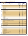
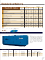
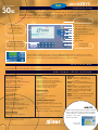
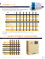
SDMO® Power Products from 650
kVA
to 3000
kVA
XS 910 K
POWER PRODUCTS
50HZ
XS 1000 K
EXEL® VOE
RANGE
(Version optimised exhaust emission)
GENERAL SPECIFICATIONS
Genset specifications
400/230 V (1)
Range
Genset
type
kVA
Cos ϕ 0,8
PRP
EXEL 1
EXEL 2
4
XS 650 K
XS 700 K
XS 825 K
XS 910 K
XS 1000 K
XS 1400 K
XS 1540 K
XS 1850 K
XS 2000 K
XS 2001 K
XS 2500 K
XS 2750 K
(5)
650
700
825
910
1000
1400
1540
1850
2000
2045
2500
2750
ESP
(6)
715
800
908
1001
1100
1540
1694
2035
2200
2250
2750
3000
kWe
ISO 8528*
PRP
(5)
520
560
660
728
800
1120
1232
1480
1600
1636
2000
2200
ESP
(6)
572
616
726
801
880
1232
1355
1628
1760
1800
2200
2400
Engine
specifications
Alternator
Compact version (3)
Engine
kWm Cons 75%
net(2) load (L/h)
Engine type
565
108 12V2000G23
599
119 12V2000G63
720 133,5 16V2000G23
805 150,6 16V2000G63
895
165 18V2000G63
1205 223 12V4000G21
1330 249 12V4000G61
1600 297 16V4000G21
1760 324 16V4000G61
1760 324 16V4000G61
2200 442
20V4000G22
2420 475 20V4000G62
Cyl.
Bore
(mm)
Stroke
(mm)
Cyl.
(L)
Brand
Type
12 V
12 V
16 V
16 V
18 V
12 V
12 V
16 V
16 V
16 V
20 V
20 V
130
130
130
130
130
165
165
165
165
165
165
165
150
150
150
150
150
190
190
190
190
190
210
210
23,9
23,9
31,9
31,9
35,8
48,8
48,8
65,0
65,0
65,0
89,8
89,8
LS
LS
LS
LS
LS
LS
LS
LS
LS
LS
LS
LS
491 M5
491 M7A
491 L9A
491 L10
501 S4
501 L 8
501 VL 10
512 S 55
512 M 60
512 L 70
53 S 75
54 S 7
Dimensions(4)
LxWxH (m)
Weight
(kg)
3,89x1,63x1,95 5200
3,89x1,63x1,95 5460
4,33x1,77x1,95 6150
4,37x1,77x2,19 6250
4,57x2,02x2,2 7160
3,87x1,84x2,21 9442
3,96x1,84x2,21 9742
4,32x1,84x2,21 11727
4,42x1,84x2,21 12022
4,52x1,84x2,21 12427
6,0x2,2x2,5
17500
6,5x2,2x2,5 18000
(1) Available voltages cf page 7 (2) Prime Power (PRP) (3) The dimensions and weights are given for a defined generator according to the price list excluding options - Soundproof version, cf p8-11
(4) Dimensions are given without cooling system (5) PRP : Prime Power – Continuous duty 24/24 h under variable load – overload acceptable 1 h / 12 h (ISO 8528 PRP) (6) ESP : Standby Power – Standby duty Operation under variable load 500 h/year without overload *ISO 8528 : Powers expressed in accordance with prevailing legislation
SDMO® Power Products from 1350
kVA
to 3000 kVA
POWER PRODUCTS
50HZ
XS 1540 F
XS 2000 F
XS 2750 F
EXEL® VOC
RANGE
(Version for minimum fuel consumption)
GENERAL SPECIFICATIONS
Genset specifications
400/230 V (1)
Range
Genset
type
kVA
Cos ϕ 0,8
PRP
EXEL 2
XS 1400 F
XS 1540 F
XS 1850 F
XS 2000 F
XS 2500 F
XS 2750 F
(5)
1350
1500
1850
2000
2500
2750
ESP
(6)
1485
1650
2037
2200
2750
3000
kWe
ISO 8528*
PRP
(5)
1080
1200
1480
1600
2000
2200
ESP
(6)
1188
1320
1628
1760
2200
2400
Engine
specifications
Alternator
Compact version (3)
Engine
kWm Cons 75%
net(2) load (L/h)
1205
1330
1600
1760
2200
2420
206
227
272
296
405
444
Engine type
Cyl.
Bore
(mm)
Stroke
(mm)
Cyl.
(L)
Brand
Type
12V4000G21
12V4000G61
16V4000G21
16V4000G61
20V4000G22
20V4000G62
12 V
12 V
16 V
16 V
20 V
20 V
165
165
165
165
165
165
190
190
190
190
210
210
48,8
48,8
65,0
65,0
89,8
89,8
LS
LS
LS
LS
LS
LS
501 L 8
501 VL 10
512 S 55
512 M 60
53 S 75
54 S 7
Dimensions(4)
LxWxH (m)
Weight
(kg)
3,87x1,84x2,21 9442
3,96x1,84x2,21 9742
4,32x1,84x2,21 11727
4,42x1,84x2,21 12022
6,0x2,2x2,5 17500
6,5x2,2x2,5 18000
(1) Available voltages cf page 7 (2) Prime Power (PRP) (3) The dimensions and weights are given for a defined generator according to the price list excluding options - Soundproof version cf. page 8-11 (4) Dimensions are
given without cooling system (5) PRP : Prime Power - Continuous duty 24/24 h under variable load - overload acceptable 1h/12h (ISO 8528 PRP) (6) ESP : Standby Power - Standby duty - Operation under variable load
500 h/year without overload * ISO 8528 : Powers expressed in accordance with prevailing legislation
5
standard
POWER PRODUCTS
50HZ
automatic oil top-up
radiator with mechanical fan
for XS 650 K to XS 1000 K
1000L daily tank
with auto pump
batteries mounted
centrifuge filter (doubles the interval
between oil changes)
6
documentation level C
& optional equipment
EQUIPMENTS
Miscellaneous
Fuel
Starting
Exhaust
Cooling
Oil
Available
voltages
Genset
Alternator
Motor
Standard and Options
4-stroke liquid-cooled diesel engine
Electronic governor
Standard air-filter
Air filter with replacable cartridge
Coolant heater 220/240 V (without relay)
Optimisation Emission(1)
Optimisation Fuel consumption
Double starter Air/Elec(2)
Double starter Elec/Elec(2)
IP 23 single-bearing alternator, class H insulation
Anti condensation heater
Tropical impregnation
Isolation and finishing work reinforced
CTP stator pick up
CTP bearing pick up
PT 100 stator pick up
PT 100 bearing pick up
Droop kit + 3 function regulator
Alternator oversizing Type
Electric panel CE compliance
Fabricated all welded baseplate with anti-vibration mountings
Standard colour RAL9005/5007 (black/blue) delivered in shrinkwrap
415-240 V@50 Hz
400-230 V@50 Hz
380-220 V@50 Hz
240-120 V@50 Hz
230-115 V@50 Hz
220-110 V@50 Hz
Supplied with oil and coolant (-30°C)
Automatic filling up oil system with oil tank
Oil centrifuge filter
Lub oil drain pump
Radiator for "air on" temperature 46°C maxi with air cooler(6)
Radiator for "air on" temperature 50°C maxi with air cooler(6)
Mounted radiator for "air on" temperature 40°C (depending on version) with drain cock(6)
Mounted radiator for "air on" temperature 50°C (depending on version) with drain cock(6)
Electrical louvres
Delivered without coolant
Protection mesh for fan and revolving parts
Front rad protection
Stainless steel bellows
Silencer 9 dB(A) supplied separately
Silencer 29 dB(A) supplied separately
Silencer 40 dB(A) supplied separately
Heat hand protection
Starter and charge alternator 24 V
Non-supply charge alternator
Battery with cables and battery tray
Non-supply of batteries and tray
Battery isolator
Generator without tank
Tank with retent. bund 500 L
Tank with retent. bund 1000 L
Retention bund alarm
Auto. Fuel fill kit (1 pump 1m3/H)
Auto. Fuel fill kit (2 pump 1m3/H)
Auto. Fuel fill kit (2 pump 4m3/H)
W separator fuel prefilter
Fuel cooling radiator
Technical documentation language to choice(7) level A(8) (1 copy)
Technical documentation language to choice(7) level A(8) (extra copy)
Technical documentation English version level B(9)
Technical documentation English version level C(10)
GENSERVICE spare parts
EXEL 1
EXEL 2
MTU 4000 series
MTU 2000 series
●
●
●
EN 02
EN 20
●
X
SO 005
SO 007
●
AL 01
AL 05 (11)
AL 06
AL 07
AL 08
AL 09
AL 10
O(3)
AO 001B
●
●
●
T51 A1
●
T51 A3
T51 C1(4)
T51 C2(4)
T51 C3(4)
●
EN 18
X
●
●(5)
●(4)
X
X
X
FD 11
●
EN 14
●
EN 07
EN 08
EN 09
CEL 02
●
X
SO 001
●
EN 16
●
FD 06
FD 07
FD 14
FD 08
FD 09
FD 10
●
X
●
AD 23
AD 31
AD 41
O
VOE
VOC
●
●
●
EN 02
EN 20
●
X
SO 005
SO 007
●
AL 01
●
AL 06
AL 07
AL 08
AL 09
AL 10
O(3)
AO 001B
●
●
●
T51 A1
●
T51 A3
X
X
X
●
EN 18
EN 19
●
X
X
●
X
CS 003
FD 11
●
X
●
EN 07
EN 08
EN 09
X
●
EN 17
SO 001
●
EN 16
●
FD 06
FD 07
FD 14
FD 08
FD 09
FD 10
●
EO 006
●
AD 23
AD 31
AD 41
O
●
●
●
EN 02
EN 20
X
●
SO 005
SO 007
●
AL 01
●
AL 06
AL 07
AL 08
AL 09
AL 10
O(3)
AO 001B
●
●
●
T51 A1
●
T51 A3
X
X
X
●
EN 18
EN 19
●
X
X
X
●
CS 003
FD 11
●
X
●
EN 07
EN 08
EN 09
X
●
EN 17
SO 001
●
EN 16
●
FD 06
FD 07
FD 14
FD 08
FD 09
FD 10
●
EO 006
●
AD 23
AD 31
AD 41
O
● Standard X Impossible O Different options available EN 01 Option code EN 01 Free option
(1) In compliance with TA LUFT requirements (2) No control panel available for this option (3) Coupling current transformer not necessary with Mics KERYS (4) Only on XS 650, 700 and 825 (5) Not available on XS 650, 700 and 825
(6) Outdoor ambient temperature, reduce of 7°C approximately (7) French or english (8) Level A documentation including : Maintenance manual and diagrams, Genset user manual and description of switchboard, Genset installation guide
(9) Level B including : level A + list of engines and alternator parts (english only) (10) Level C including : Level B + workshop manual (english only) (11) Standard for XS 1000
7
Contenergy®
POWER PRODUCTS
50HZ
From 650 to 2250 KVA, SDMO® offers great adaptability with the Contenergy® concept.
Three standard versions are proposed, depending on your requirements,
and enable you to benefit from reduced costs and delivery times.
Super Silent ® Super Silent ®
Silent
Silent
85-87 dB(A)@1M
84-86dB(A)@1M
78-80 dB(A)@1M
82-84dB(A)@1M
12 V 2000
ISO 20 SI
X
CIR 20 SSI
X
XS 825 - XS 910
16 V 2000
ISO 20 SI
X
CIR 20 SSI
X
XS 1000
18 V 2000
ISO 20 SI
X
CIR 20 SSI
X
XS 1400 - XS 1540
12 V 4000
ISO 40 SI
X
EUR 40 SSI
CIR 20 SSI
XS 1850 - XS 2000 - XS 2001
16 V 4000
X
EUR 40 SI
EUR 40 SSI
X
Range
EXEL
Genset type
Engine
XS 650 - XS 700
For XS 2500 K and XS 2750 K, please contact us
ISO 20
The ISO Contenergy® are designed in accordance with dimensions defined by the ISO/TC104(1) standards. This
design enables during transport to endure without damage high pressures and big loads and to travel by boat
without specific constraints.
Two sizes are available : 20 and 40 feet High Cube.
(1) The ISO / TC 104 standard includes the ISO 668, ISO 1496-1, ISO 830, ISO 1161, ISO 3874, ISO 6346 standards and ensures the CSC certification.
8
Standards containers
CIR 20
The CIR version is built on an ISO 20’ Contenergy® base. This very compact model is more specifically suited for
rental and mobile applications thanks to its high capacity and its low sound level.
Compliance with the ISO/TC104(1) standard upon request.
EUR 40
Dedicated to generator sets fitted with MTU-DDC Series 4000 motor, the EUR Contenergy® offers, for a single base,
two noise level variations : Silent and Super Silent.
This soundproofed version also offers features such as side doors or a daily tank.
9
POWER PRODUCTS
50HZ
Contenergy®
The CONTENERGY containers
can be installed on a concrete slab
(fitted with ducts for the cabling
and piping) or simply on a hard
surface. This CONTENERGY
concept is very simple and
economical, thanks to its integrated
cooling system, silencer and sound
traps.
You have many installation requirements and SDMO knows it.
It is for this reason that our containers are designed, in
particular, to withstand dificult climatic conditions.
Whether your installation needs to withstand extreme cold
conditions or has to operate in a tropical climate, tell us what
you need, we probably have the solution to your problem.
International standards-compliant trailers are also available, thus
enabling you to transform your generator set into a mobile unit
(contact us for further details).
10
Standard containers
SUPER SILENT®
SILENT
Dimensions Panels
Fuel
Specifications
Base
Standard & Options
Base girder
Starter, charging alternator 24 V
Batteries with electrolyte
Standard air-filter
Lub oil drain pump
Sound-proofing type
Highly efficient silencer built in - attenuation 30 db(A)
Floor
Number of doors
Air outlet galvanized steel rain guard grid
Emergency light and emergency fuel valve
Exhaust exit on flanges
White paint finishing (RAL 9010)
Catch pit under the whole of the container
Tank without retent. bund 500 L
Tank with retent. bund 500 L
Tank with retent. bund 2347 L + client connection terminal strip
Auto. Fuel fill kit (1 pump 1 m3/H)
Auto. Fuel fill kit (2 pump 1 m3/H)
Auto. Fuel fill kit (2 pump 4 m3/H)
Electric panel EC compliance
Panel Mics TELYS
Panel Mics KERYS
Length (mm)
Width (mm)
Height (mm)
Standard
X Impossible
EN 01 Option code
M 427
ISO 20 SI
ISO 40 SI
EUR 40 SI
CIR 20 SSI
EUR 40 SSI
●
●
●
●
●
●
●
●
●
●
SO001
SO001
SO001
SO001
SO001
●
●
●
●
●
●
●
●
●
●
SSI
SI
SI
SI
SSI
●
●
●
●
●
Bois
1
CT 005
CT 007
CT 011
Bois
1
CT 005
CT 007
CT 011
Bois
2
Acier étanche
2
Bois
2
●
●
●
CT 007
CT 011
CT 007
CT 011
CT 007
CT 011
●
●
●
●
●
CT 014
CT 014
X
CT 014
X
CT 014
CT 014
X
●
●
X
CT 008
CT 009
CT 010
X
CT 008
CT 009
CT 010
X
CT 003
CT 008
X
X
●
X
X
CT 008
X
X
●
●
X
CT 008
CT 009
CT 010
●
●
●
●
●
CM 40
CA 600
6058
2438
2896
CM 40
CA 600
12192
2438
2896
CM 40
CA 600
6058
2438
2896
CM 40
CA 600
12192
2438
2896
CM 40
CA 600
12192
2438
2896
EN 01 Free option
NEW
PRESENTATION
SDMO now offers a sound-proof hood
for your EXEL generator set fitted with
an MTU 12V2000 or 16V2000 motor.
You thus optimise your installation’s footprint
and can even fit the assembly into a 40“
High Cube container in order to facilitate
transport.
CHARACTERISTICS
Genset type
Canopy
XS 650 K
XS 700 K
XS 825 K
XS 910 K
427
427
427
427
Tank
(L)
930
930
930
930
Dimensions
L x w x h (m)
6,40x2,17x2,72
6,40x2,17x2,72
6,40x2,17x2,72
6,40x2,17x2,72
Weight(1)
(kg)
7876
8011
8579
8709
Sound level - 50 Hz
dB(A)@1m
dB(A)@7m
79,9
70
80,4
71
82,8
73,2
83,5
74
(1) Dry weight, without fuel
11
electrical panels
POWER PRODUCTS
50HZ
Three control cabinets are available in our 650 to 3,000 kvA range : the M80, the Mics TELYS and the
Mics KERYS. In order to guarantee a high degree of modularity and standardisation, each optional peripheral
device (aero, RJ, oil top-up) possesses its own protection.
For plants, an auxiliary cabinet containing the mains detection and preheating controls can be fitted, along with
separate cabinets.
M 80
PRESENTATION
The M80 cabinet is a direct display control panel. Its various dials provide a global overview of our generator set’s basic
parameters.
Tachometer
Oil
pressure
Water
temperature
Emergency
stop button
Timer
SPECIFICATIONS
M 80
Tachometer (54 mm)
●
●
Engine
parameters
Timer
Oil pressure gauge
Water temperature display
Oil pressure display
●
O
O
Operation
Emergency stop
●
Miscellaneous
CE Compliance
Client connection terminal strip
●
Standard
12
Instruments
O Option code
●
MICS
TELYS
PRESENTATION
A major component of our range of control units, the Mics TELYS is a standard addition to our generator sets from 200 kVA
upwards its user-friendly interface and range of features allow careful monitoring of your installation.
1 “ON” KEY
with integrated LED
(after automatic extinction)
LCD SCREEN
4 electrical QUANTITIES
incorpored back-lighting,
featuring 8 lines x 21 characters
AND ENGINE
PARAMETERS KEYS
8 DISPLAY LEDS
des alarmes, defauts, états
15 PROGRAMMING
KEYS
1 - Oil pressure fault (R)
2 - Water temperature fault (R)
3 - Failure to start fault (R)
4 - Overspeed fault (R)
5 - Set ready to output (G)
6 - Charging alternator fault (R)
7 - General alarm (Y)
8 - General fault (R)
NUMBER KEY PAD
(0 TO 9)
4 OPERATING MODE
SELECTION KEYS
with integrated selection LEDs
(R = red, G = Green, Y = Yellow)
2 ERROR RESET
2 generating SET REGULATION
AND LED TEST KEYS
OUTPUT KEYS
(+/-)
Standard
O Option code
LCD Standard with LCD message
Safety devices
● LCD
● LCD
● LCD
● LCD
● LCD
● LCD
O
O
● LCD
● LCD
● LCD
●
●
●
O
O
O (3)
O (3)
●
●
●
●
●
●
●
●
●
●
O (3)
O (3)
● LCD
Automation
Line voltages in Volts
Single voltages in Volts
Phase currents in Amps
Neutral current in Amps
Frequency in Hertz
All generating set states, all starter phases
Analogical indicator
Ammeter battery
Indication of engine speed
Indication of battery voltage
Elapsed hour meter
Powering up
Fuel solenoid-operated valve control
Starter control
Plug preheating control
Water preheating control
Mains contactor control
Generating set contactor control
Oil pressure fault
Water temperature fault
Fail to start fault
Overspeed fault
Set ready for load
Charging alternator fault
General alarm
General fault
Panel lamp, 22 dia.
STOP/MANU/AUTO/TEST mode
Generating set side contactor closed
Mains side contactor closed
Any faults or any alarms messages
Miscellaneous
Operation and/or safety lights
Operation
Engine
Parameters
Measurements
SPECIFICATIONS
Oil pressure fault
Water temperature fault
Emergency stop fault
Overload or short-circuit alarm or fault
Min/max battery voltage alarm or fault
Min/max alternator voltage alarm or fault
Min/max alternator frequency alarm or fault
Overspeed fault
Differential relay present fault
Differential triggering alarm or fault
Automatic standby
Automatic extinction
4 modes
Engine stopping for cooling
Voltage and speed stabilization
Plug preheating
ATS changeover presence choice
Mains contactor position return
Generating set and mains contactor position return
Generating set contactor manual closing
Generating set contactor manual opening
Starting on clock
External starting order
Mains sensing 3-ph
Test LEDs
Fault reset
External AMF predisposition
3-phase with or without neutral, 2-phase or single-phase use
12V battery charger
GES Pack(6) fitted inside the genset(7)
Differential protection with time and sensitivity adjustment
Alarm hooter
●
●
●
● (2)
● (2)
● (2)
● (2)
●
O (3)
O (2+3)
●
●
●
●
●
O
O (1)
O (1)
O (1)
O (1)
O (1)
O (1)
O (1)
O (4)
●
●
O
● (5)
O
O
O (2)
O
(1) Control and automatisms installed, but necessity to have the option "External AMF predisposition" and the possible configuration of one parameter on the MICS®
Telys (2) The choice Alarm or Fault is programmed through the keyboard (3) The earth fault protection is ensured by one external module connected to the CB12
card and through connecting of one tiny relay on the CB12 card. A local configuration is also needed (4) MICS DS mains detection is proposed as a base in the
source inverter. In the case whereby the source inverter is not chosen, the MICS DS module can be moulded in the panel (5) Choice is revised through
programming - The alternator's voltage reference connecting wire modification is necessary (6) For details, please consult us (7) NF E37312 standard
This software developed by SDMO enables the user to set up the dialog between the Mics TELYS panel fitted
on our gensets and the PC type computer on which it is installed in order to control from a distance the operating
system. Depending on the configuration of your installation, you can select from 4 types of connection, the one
that best suits your needs : local mode supervision, Switched Telephone Network remote management, Ethernet
remote management or SGM network remote management. For further information concerning Wintelys, please
contact an SDMO reseller.
.
13
NEW
POWER PRODUCTS
50HZ
MICS KERYS
PRESENTATION
The Mics KERYS is a user-friendly and intuitive tool that possesses a very broad range of features. It is fitted as
standard on all generator sets intended foe coupling applications and can be fitted as an option on all of our
other applications. in order to meet all of the requirements of low or high voltage power plants, the Mics
KERYS can be fitted into a control desk, directly onto the generator set, or in a separate cabinet.
It complies with EC, UL and CSA standards.
Control keypad
with display LED
Manu mode selection
Stop mode selection
Auto mode selection
Open/Close GE circuit breaker
Activate/Deactivate test
Open/Close network circuit breaker
LED test
Stop horn
Erase anomalies
Display screen
TFT LCD 7,4 in
Colour graphical display
Touch screen
Dimensions 154 x 86 mm
Configuration keypad
For configuration, navigation
and direct access to screens
Control keypad
with display LED
The Mics KERYS is available in two versions. The basic GUI (Graphical User Interface) is made up of a monochrome
LCD screen and a function keypad. The top of the range Mics KERYS tactil version possesses a TFT colour touch screen.
Both of these versions provides a user-friendly configuration, operation or diagnostic interface.
SPECIFICATIONS
The Mics KERYS possesses all of the features of the Mics TELYS (cf. table page 13)
ADDITIONAL SPECIFICATIONS
Measurements
Powers (active, reactive)
Power factor in the various dials
Active and reactive energies
Synchronism (phase, voltage and frequency
deviation)
Voltage and current harmonics
Protective measures
Overload, short-circuit
Line current directive
Neutral current
Reverse component
Voltage hold-back
Thermal image
Voltage max. and min.
Presence and absence of voltage
Frequency max. and Min.
Active poxer maximum
Active and reactive reverse power
Homopolar current and homopolar current
directive
Homopolar voltage and restricted earth
Vector jump, mini Z and dF/dt
Synchronisation
Manual and automatic
Frequency and voltage equalisation
Control
Speed and voltage
Frequency and voltage setpoint switching
Frequency and voltage setpoint adjusment
Active and reactive power setpoint adjustment
Active and reactive power ramp-up
Active and reactive power distribution
Active and reactive power lock-out
manual speed and voltage control
Communication
Local or remote mode
On board Web site
RS485 link
Ethernet (local mode) and Internet
(remote mode)
Standard added benefits
Failure troubleshooting assistance
Maintenance assistance (logs, automatic Email,
etc.)
Electrical and mechanical parameter graphs and
logs
Load impact management
Addition of extra logics with no external tools
Coupling
A612 : Generator set without grid
A622 : Generator set with INS and grid,
no coupling
A633 : Production plant without grid
A634 : Production plant with grid and INS (no
grid coupling)
A641 : Generator set with permanent grid
coupling, no INS - grid coupling + resale
A642 : Generator set with permanent grid
coupling, no INS - Grid coupling + 0 kW
power cap on grid
A651 : Generator set with fading grid coupling
and INS
A661 : Generator set with permanent grid
coupling and INS WEB site
WEB SITE
The Mics Kerys and Kerys tactil are provided as standard
with an on-board web site. This site and its 60 resident
screens enables you to completely check your installation
(operation and setup),
whatever the distance.
For further information, check the Mics KERYS documentation
or contact your SDMO sales representative.
Electrical variable
display screen
14
POWER MODULES AIPR
CHARACTERISTICS
1250 A
1600 A
2000 A
2500 A
3200 A
●
●
●
●
✕
✕
✕
✕
✕
✕
✕
●
●
●
O
O
O
O
✕
✕
✕
✕
✕
✕
✕
O
O
O
O
O
O
O
O
O
O
●
O
●
●
IP207
1260
665
360
1664
665
360
●
O
●
●
IP207
1260
665
360
1664
665
360
●
O
●
●
IP207
1260
665
360
1664
665
360
●
O
●
●
IP207
1260
665
360
1664
665
360
●
O
●
●
IP207
1260
665
360
1664
665
360
●
O
●
●
IP207
1260
665
360
1664
665
360
●
O
●
●
IP207
1260
665
360
1664
665
360
800 A
AIPR
1000 A
Each genset can be delivered with a protection panel.
This panel is fitted on the generating set frame with the connecting cables onto the
alternator. Depending on the type and power of the engine, the panel AIPR can be
positioned wether on the right or left hand side of the generating set.
Rating
WITH A FRONT MANUAL COMMAND
3 poles power circuit breaker
Compact type
3 poles power circuit breaker
Open type
4 poles power circuit breaker
Compact type
4 poles power circuit breaker
Open type
OPTION
OPTION MOTORIZED
MOTORIZED CONTROL
CONTROL **
With 3 or 4 poles circuit breaker
Only open type
Voltage 208-440V
Option power auxiliaries panel (**)
Bus bars
Remote control terminal box
Protection index
Dimensions :
height (mm)
(without optional panel) width (mm)
depth (mm)
Dimensions :
height (mm)
(with optional panel)
width (mm)
depth (mm)
(*) The motorized remote control includes : one XF coil, one MX coil, and one AC engine.
(**) The optional panel "power auxiliary" is fitted above the main panel. It is used for the genset auxiliaries power connection, i.e :
- air cooler supply
- fuel pump supply
SEPARATE
“MAINS/STANDBY” CHANGEOVERS
INS 2000 A
INS 2500 A
INS 3200 A
2 poles
X
3 poles
●
4 poles
●
208-440V (3-phase)
●
220-240V (1-phase)
X
Changeover by contactor
●
Changeover by motorised CB
X
Protection of auxiliaries (1)
C/B
Terminals
X
Copper bars
●
Height (mm)
1200
Width (mm)
1200
Depth (mm)
400
Adjustable mains sensing relay ●
Wall panel IP 54
●
Free-standing panel IP 54
X
INS 1600 A
DIMENSIONS
CONNECTION
VOLTAGE
INS 1000 A
GENERAL SPECIFICATIONS
X
●
●
●
X
●
X
C/B
X
●
2000
1200
500
●
X
●
X
●
●
●
●
X
●
C/B
X
●
2000
800
800
●
X
●
X
●
●
●
●
X
●
C/B
X
●
2000
800
800
●
X
●
X
●
●
●
●
X
●
C/B
X
●
2000
800
800
●
X
●
● Standard O Option X Impossible (1) Protection of auxiliaries : mains power detection, panel relay, water heater, battery charger
15