1
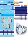
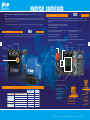
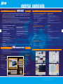
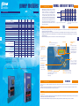
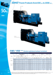
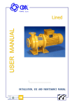
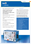
SDMO Gennevilliers
Tel. 01 41 88 38 00 - Fax 01 41 88 38 37
EAST
SDMO Metz
Tel. 03 87 37 88 50 - Fax 03 87 37 88 59
SDMO Valence
Tel. 04 75 81 31 00 - Fax 04 75 81 31 10
SDMO Aix
Tel. 04 42 52 51 60 - Fax 04 42 52 51 61
SOUTH WEST
SDMO Toulouse
Tel. 05 61 24 75 75 - Fax 05 61 24 75 79
SPAIN
SDMO INDUSTRIES IBERICA
Tel. +34 902 30 56 56 - Fax +34 93 580 31 36
US
SDMO GENERATING SETS
Tel. +1 305 863 00 12 - Fax +1 305 863 97 81
UK
SDMO ENERGY Ltd
Tel. +44(0) 1932 345 777 - Fax +44(0) 1932 350 033
NIGERIA
w
ay
SDMO LAGOS
Tel +234 (0) 80 56 66 64 44 - Fax + 33 (0) 1 72 27 55 62
d.
SDMO GmbH
Tel. /FAX. +49 (0)6332 97 150
su
n
GERMANY
gp
Offices
SOUTH AFRICA
SDMO JOHANNESBURG
Tel. +33 (0)631 594 701 - Fax +33 (0)172 276 151
ALGERIA
SDMO ALGER
Tel. +213 (0)21 68 12 12 - Fax +213 (0)21 68 14 14
DUBAI
SDMO MIDDLE EAST
Tel. + 971 50 51 496 83 - Fax +33 (0)1 72 27 55 52
RUSSIA
SDMO MOSCOW
Tel. +7 926 838 05 34 – Fax +33 (0) 1 72 27 55 48
SDMO Industries - 12 bis rue de la villeneuve
CS 92 848 - 29 228 Brest Cedex 2 - France
Tel. +33 (0)2 98 41 41 41 - Fax +33 (0)2 98 41 63 07
www.sdmo.com
5268-10.08.L
PPRPAC/2009/1 - 50HZ 60HZ - English
SOUTH EAST
BRAZIL
SDMO DO BRAZIL
Tel. +55 (11) 43 908 434 - Fax +55 (11) 43 908 434
.cn
PARIS/NORTHERN NORMANDY
BELGIUM
SDMO NV/SA
Tel. +32 3 646 04 15 - Fax +32 3 646 06 25
m
SDMO CHOLET
Tel. 02 41 75 96 70 - Fax 02 41 75 96 71
co
CENTRAL WEST
fo
.
SDMO BREST
Tel. 02 98 41 13 48 - Fax 02 98 41 13 57
ARGENTINA
SDMO ARGENTINA S.A.
Tel. +54 114 836 35 11 - Fax +54 114 836 35 16
in
WEST
Subsidiaries
SDMO is a registered trademark of SDMO Industries.
Non contractual document - In accordance with our product quality improvement policy, SDMO Industries reserves the right to modify, without prior notice, any specifications published in this catalogue. Photo credit: SDMO - Guillaume Team
French Offices
SDMO industries
Implantation en France
Pacific
Power Products
PPR-PA-DO-GB-01
50HZ 60HZ
1275kVA - 2200kVA
1091kWe - 2000kWe
Whether you require emergency power to be able to cope with potential power cuts (e.g. hospitals, shopping centres) or continuous
power when conventional electrical grids are faulty (power plants), SDMO will be able to offer you performance products from a
large range which meets all the requirements of different markets.
This range comprises 3 main categories:
- Standard products (Portable Power, Residential Power, Power Products and Rental Power)
- Expertise and Services (Power Solutions, Training, Spare Parts, Technical Assistance)
- Related products (NEXYS, TELYS, KERYS command/control units)
A powerful response
National coverage,
international presence,
‘‘think globally,
act locally‘‘
SDMO is recognised as one of the top manufacturers of
g e n e r a t i n g s e t s in the world. SDMO has channelled all
its energy into designing a range which is both highly competitive
and high-performance, the largest range available on the market.
As a response to the increasingly precise nature of your energy
requirements, which relate directly to the special traits of your
particular industry, SDMO is devoting the majority of its resources to
the continuous improvement of its range and services.
The result of a strategy focussed on a single industry: exacting
professionalism which provides you with a reliable source of energy,
complying with the strictest of standards. The pioneering mindset of
its teams, and the mastery and flexibility of its production methods
mean that SDMO is constantly innovating. The proximity of its
distribution network and dynamism of its customer services policy
enable SDMO to be a powerful force and provide the basis of the
company's values.
The reactivity of the company is based on its 5 storage
platforms which, in co-operation with the subsidiaries,
constitute an efficient means of operating.
The links forged with the Kolher group have strengthened
SDMO's standing amongst its customers through a strategy
of synergistic installations.
co
m
.cn
In order that SDMO can continue to grow and expand into
new markets, it relies on:
- a distribution network present in over 150 countries,
- 8 overseas subsidiaries,
- 4 offices,
- 7 sales offices and 3 regional HQs in France.
gp
d.
su
n
w
ay
in
fo
.
SDMO, the source of energy for your comfort and safety.
SDMO, providing the energy that links mankind.
whatever
the energy required
SDMO Head Office
SDMO locations
Market logic for greater
reactivity
The production plants in Brest are organised according to
product lines relating to the product range offered:
www.sdmo.com
Agents/Distributors
SDMO Stock
- a production site for Portable Power generating sets and
for Power Products with lower power,
- a production site for Power Products, Rental Power and
Residential Power ranges,
- a production site used for the production of special Power
Solutions applications.
This overall synergy between industrial teams and sales and
marketing departments reinforces the position of SDMO:
prescription, reactivity, presence on the major markets.
PACIFIC 50Hz range
50HZ 60HZ
Generating sets in
the PACIFIC range
feature a winning
combination:
robust design and ease
of use.
PACIFIC 60Hz range
50HZ 60HZ
T1400
T1800U
5
T1650C
gp
d.
su
n
w
ay
in
fo
.
co
m
.cn
4
T2000U
50Hz RANGE
TECHNICAL SPECIFICATIONS
Generating set specifications
400-230 V
RANGE
PACIFIC II
kVA
Cos 0.8
PRP
ESP
Cons 3/4
L/h
T1400
1275
1403
208
T1540
1400
1540
T1650C
1500
1650
T1900
1727
1900
T2100
1909
2100
T2200
2000
2200
(2)
Generating set specifications
480-277 V
Engine specifications
GENERATING
SETS (1)
Alternator
Open Version (4)
Engine type
cyl
Bore
(mm)
Stroke
(mm)
Cyl
(L)
Type
Dimensions
lxwxh (m)
Weights(5)
(kg)
S12R-PTA
12
170
180
49.03
502 L7
4.33x2.00x2.37
9781
218
S12R-PTA2
12
170
180
49.03
502 L8
4.42x2.00x2.37
10147
240
S12R-PTAW
12
170
180
49.03
502L8
5.90x2.20x2.51
12153
266
S16R-PTA
16
170
180
65.37
512S55
5.50x2.29x2.48
304
S16R-PTA2
16
170
180
65.37
512M60
5.60x2.29x2.48
307.3
S16R-PTAA2
16
170
180
65.37
512M60
5.50x2.29x2.58
14371
(3)
60Hz RANGE
TECHNICAL SPECIFICATIONS
(1)Also available in the following voltages: 415/240 V - 380/220 V
(2)PRP: Main power available continuously under variable load for an unlimited number of hours annually,
in accordance with ISO 8528-1, an overload of 10% one hour every 12 hours is available in accordance with
ISO 3046-1
(3)ESP: Emergency Standby Power available for supplying emergency power in variable load applications in
accordance with ISO 8528-1, no overload available for this service.
RANGE
GENERATING
SETS (1)
kWe
ISO 8528(2)
PRP
ESP
1091
1200
(3)
T1200U
Engine specifications
Cons
3/4 L/h
Alternator
Open Version (5)
Engine type
cyl
Bore
(mm)
Stroke
(mm)
Cyl
(L)
Type
Dimension
lxwxh (m)
Weights(6)
(kg)
229
S12R-PTA
12
170
180
49.03
501M7
4.33x2.00x2.37
9781
(4)
T1350U
1228
1350
250
S12R-PTA2
12
170
180
49.03
501L8
4.42x2.00x2.37
10147
T1600U
1455
1600
294
S16R-PTA
16
170
180
65.37
512S55
4.43x2.29x2.48
12891
12891
T1800U
1636
1800
346
S16R-PTA2
16
170
180
65.37
512S55
5.50x2.29x2.48
12991
13314
T2000U
1818
2000
357
S16R-PTAA2
16
170
18
65.37
512M60
5.50x2.29x2.58
14371
(4)The dimensions and weights apply to a generating set specified in the price list, without options
(5)Dry weight - without fuel
PACIFIC II
(1)Also available in the following voltages: 440 V - -254 V
(2)ISO 8528: powers specified in compliance with the legislation in force
(3)PRP: main power available continuously under variable load for an unlimited number of hours annually, in
accordance with ISO 8528-1
(4)ESP: Emergency Standby Power available for supplying emergency power in variable load applications in
accordance with ISO 8528-1, no overload available for this service
(5)The dimensions and weights apply to a generating set specified in the price list, without options
(6)Dry weight - without fuel
The CONTENERGY concept
EQUIPMENT
1 EN02
Air filter with interchangeable cartridge
•
X
O
EN 21
FD 01
As standard
Not possible
Several possible options
contact us
Option code
Free option
2
EN16
Battery isolating switch
(1)
(2)
(3)
3
3
Highly economical thanks to its cooling system, integrated sound traps and silencers, the CONTENERGY concept
is completely self-contained, with a fuel capacity which enables it to operate immediately, without connection to
an additional tank.
SDMO understands the many factors that have an influence on your equipment's operation. That is why our
containers are designed to withstand harsh climate conditions.
Whether your equipment needs to operate in extreme cold or tropical environments, let us know your requirements
- we are sure to have the solution you're looking for.
Trailers compliant with international standards are also available, allowing you to transform your generating set
into a mobile unit (please contact us)
fo
.
co
m
.cn
7
in
ay
3 AD21 and AD 22
User manual and commissioning guide
Synchronising CT coupling not required for Mics KERYS
Outdoor ambient temperature, reduce by approximately 7°C
Additional copy
contenergy
Thanks to their standard dimensions, CONTENERGY containers are easy to transport and, once on site, very simple
to install: we would recommend that you install them outside the building on a concrete floor plate fitted with a
tunnel for the cables and pipes.
w
2
INTRODUCTION
The CONTENERGY concept offers a range of soundproof containers featuring a multitude of options
su
n
1
•
•
•
EN 02
EN 20
•
AL 01
•
AL 06
AL 07
AL 08
AL 09
AL 10
O(1)
AO 001B
•
•
•
•
EN 18
•
•
FD 11
•
EN 14
•
EN 07
EN 08
EN 09
•
SO 001
•
EN 16
•
FD 06
FD 07
FD 14
FD 08
FD 09
FD 10
FD 05
•
AD 21
AD 22
AD 31
AD 32
AD 41
AD 42
O
d.
diesel
starting
exhaust
cooling
oil
generating
set
alternator
engine
4 stroke water-cooled diesel engine
Electronic control device
Standard air filter
Air filter with interchangeable cartridge
220/240 V preheating resistance (no control)
IP 23 single bearing alternator, T° class =H, insulation class H/H
Anti condensation resistor
Reinforced insulation
Reinforced insulation and finish
Stator PTC sensor
Bearing PTC sensor
Stator PT 100 sensor
Bearing PT 100 sensor
Synchronising CT coupling + 3 function regulator
Oversized alternator
CE compliance of the control unit
Mechanically welded base frame with antivibration dampers
Supplied in colour RAL 9005/5007 (black/blue) delivered in shrink-wrap film
Supplied with oil and coolant -30°C
Automatic oil top up with tank
Oil drainage pump
Radiator core temperature of 50°C max with mechanical fan (2)
Supplied without coolant
Protective grille for fan and rotating parts
Protective grille for radiator core
Stainless steel compensators
9 dB(A) silencer supplied separately
29 dB(A) silencer supplied separately
40 dB(A) silencer supplied separately
24 V charging alternator and starter motor
Batteries with cables and battery support bracket
No battery and battery support bracket
Battery isolating switch
Generating set without fuel tank
Separate fuel tank on 500 l container
Separate fuel tank on 1000 l container
Retention container level alarm
1m3/h pump auto kit 1
1m3/h pump auto kit 2
4m3/h pump auto kit 2
Diesel separator pre-filter
User manual and commissioning guide (paper version) - French, English or Spanish
User manual and commissioning guide (paper version) - French, English or Spanish (3)
User manual and commissioning guide (CD version) - French, English or Spanish
Engine parts catalogue (paper version) - English
Engine parts catalogue (CD version) - English
Engine repair and workshop manual (paper version) - English
Engine repair and workshop manual (CD version) - English
GENSERVICE replacement parts
accessories
6
PACIFIC II
Basic and options
gp
basic and options
50HZ 60HZ
The CONTENERGY design
means that one simple
connection is all it takes
to get your power plant
up and running.
Conternergy
50HZ 60HZ
Standard containers
basic and options
contenergy
INTRODUCTION
CONTENERGY ISO
Basic
Base member
Starter motor, 24 V charging alternator
Batteries filled with electrolyte
Standard air filter
Oil drainage pump
Type of soundproofing
High performance integrated 30 dB(A) silencer
Floor
Number of doors
Galvanised air outlet rain grille
Safety lighting and shut-off valve
Exhaust outlet on bracket
RAL 9010 white painted finish for container
Special colour from list
Power cable outlet on lower section
Retention container under container assembly
500 l base frame fuel tank
Tank on container (500 l)
Tank on container (2000 l)
External terminal block
1m3/h pump auto kit 1
1m3/h pump auto kit 2
4m3/h pump auto kit 2
CE compliance of the control unit
MICS Telys control unit
MICS KERYS control unit
Length (mm)
Width (mm)
Height (mm)
Container specifications
To protect the environment, our containers may
be fitted with an optional
retention container to hold
all engine fluids.
Our containers comply with all current standards and regulations governing these products, including:
gp
d.
ISO20 (Silent)
1275kVA - 1540kVA
ISO40 (Silent)
1700kVA - 2100kVA
T1400 - T1650C
T1200U - T1350U
T1900 - T2100
T1600U - T1800U
Engine
S12R
S12R
S16R
S16R
SILENT
SUPER SILENT
SILENT
85 - 87 dB(A)@1 m 82 - 84 dB(A)@1 m 79 - 82 dB(A)@7 m
ISO 20 Si
CIR 20 SSi
X
X
X
ISO 20 Si
ISO 40 Si
X
X
X
X
ISO 40 Si
SUPER SILENT
77 - 79 dB(A)@7 m
X
CIR 20 SSi
X
X
Dimensions
su
n
w
ay
in
foControl
.co
units
m
.cn
Fuel
- ISO 668
- NF90-005
- NF ISO 1496-1 (ISO 8323)
Generating set type
SILENT
Basic and options
CONTENERGY CIR
8
EQUIPMENT
basic and options
The dimensions of CONTENERGY ISO containers comply with CSC certification. They have been specially
designed to withstand significant loads and pressures during transport without incurring damage, and can
be shipped without any special constraints.
They are available in two sizes: 20 and 40 feet “High Cube”.
CIR type containers are specially designed with mobile and rental applications in mind. This highly compact
model has a very low sound level and features an optional high volume tank, giving it up to 10 hours of
autonomy.
This model is available as a 20 feet “High Cube”
50HZ 60HZ
•
As standard
X
Not possible
EN 01 SUPER SILENT
ISO 20 Si
ISO 40 Si
CIR 20 SSi
•
•
SO 001
•
•
Si
•
Bulb plate
2
CT 005
CT 007
CT 011
•
CT 016
CT 015
CT 014
•
X
X
CT 018
CT 008
X
X
•
CM 40
CA 600
6058
2438
2896
•
•
SO 001
•
•
Si
•
Bulb plate
2
CT 005
CT 007
CT 011
•
CT 016
CT 015
CT 014
X
•
X
X
CT 008
CT 009
CT 010
•
CM 40
CA 600
12192
2438
2896
•
•
SO 001
•
•
SSi
•
Bulb plate
3
•
CT 007
CT 011
•
CT 016
CT 015
CT 014
•
X
CT 017
CT 018
CT 008
X
X
•
CM 40
CA 600
6058
2438
2896
Option code
CT 011
Free option
9
electrical control units
50HZ 60HZ
Three control units are available in our 650 to 3000 kVA range: the M80, the TELYS (previous pages) and the
KERYS.
Your control unit can be chosen according to your equipment type and perfectly adapted to suit your needs with the options
available. This modularity is made even easier by the fact that each optional peripheral device (air cooler, daily service tank,
oil top-up, etc.) has its own protection.
Telys, SDMO's flagship product, integrates new options and offers improved ergonomics and a more user-friendly design. It is even
more straightforward, with the emphasis on communication (USB connections, PC connections, control software and remote
operation).
Its design, inspired by the NEXYS, has reduced the number of
buttons to offer you simplicity when operating your generating
set. It also offers new functions:
For power plants, separate control boxes may be used in place of the control units: please do not hesitate to contact us.
M80
INTRODUCTION
The M80 control unit has a dual functionality. It can be used as a basic terminal block for connecting a control box and as an instrument
panel with a direct read facility, with displays giving a global view of your generating set's basic parameters.
10
TELYS
INTRODUCTION
- Integrated maintenance monitoring programme (on-screen
display of required maintenance operations)
- Card tropicalisation possible to compensate for
extremely humid conditions (b)
- On-board service tool to guide the user
when a warning or fault is detected
- Compliance with numerous legal
and regulatory requirements (EC)
- Viewing and remote control functions with option to send(b) an
E-mail, text message or fax in the event of a warning or a fault
- Screen with contrast which adjusts to all types of light
(b) As an option
Coolant temperature
Tachometer
Emergency
stop push
button
m
11
"Telys live" LED
ON/OFF key
Fuse
Generating
set stop
button
d.
su
n
w
ay
in
fo
.
co
Emergency
stop button
Generating set start button
ESCAPE
button
.cn
Oil pressure
Alarm LEDs
2 USB ports under
Fault LEDs
sealed cover
gp
Menu access
button
Scrolling and
validation
wheel
TELYS
THE
Display screen composed of 4 zones:
ZONE 1: Operation mode
(generating set running/auto/manual)
SPECIFICATIONS
Measurements
Engine parameters
Controls
Miscellaneous
BASIC TERMINAL
BLOCK
M 80
Tachometer (54 mm)
X
•
Oil pressure gauge
X
•
Coolant temperature indicator
X
•
Oil temperature indicator
X
O
Emergency stop
•
•
CE compliant
•
•
Customer connection terminal block
•
As standard
X
Not available
•
O
FIGURES
ZONE 2: Display of functions via
pictograms
•
ZONE 3: Display of mechanical and
electrical values and the associated
measurements
ZONE 4: Operating messages and
parameter settings menu
The TELYS can now be fitted with
display and remote control
options, allowing the generating
set to be actively monitored and
managed for increased safety.
Operation at
-20°C to +60°C
Humidity:
95% to 45°, 70% to 50°C,
50% to 60°C
5 language options,
numerous languages
Option to connect
up to 5 additional
I/O modules
(4 inputs/6 outputs) (b)
Options
For more information on the TELYS, please refer to the TELYS documentation (TEL/FR-2007) or speak to your SDMO sales representative
electrical control units
KERYS TACTIL
INTRODUCTION
The KERYS tactil command and control unit has been designed to fulfil the specific
requirements of professionals in terms of managing and monitoring generating sets. It
therefore offers a wide range of functions.
This control unit is fitted as standard to all generating sets designed to be used for coupling
and is offered as an option across the rest of our range.
The KERYS tactil can be built into the central console, fitted directly on the generating set, or
in a separate cabinet, to fulfil all the requirements for low and high output power plants.
MEASUREMENTS AND DISPLAYS
GRAPHS AND ARCHIVING OF ELECTRICAL AND
MECHANICAL PARAMETERS
Adjustable sampling and configurable triggering criteria.
Mechanical:
• Temperatures,
• Pressures and levels, depending on engine configuration
Electrical:
• Voltages,
• Currents,
• Frequency and power,
• Power factor,
• Outputs,
• Mechanical and electrical metering.
Man-machine interface module
The man-machine interface is available with a colour screen and a 7-inch touch panel. The MMI module is equipped
with all the keys required to ensure the generating set can be controlled and the system configured, thanks to a screen
navigator and an alphanumeric keypad.
Alphanumeric keypad
For setting parameters,
navigation and direct
access to screens
• Built-in web server
• User-friendly man-machine interface
• 5 basic languages (French, English, Spanish, Portuguese, German), one of which is interchangeable (please consult us)
• Ethernet Port
• Dialogue with all engines equipped with a built-in ECU
• RS 485 port for Modbus RTU
• RS 232 port
• Option of PSTN communication (Public Switched Telephone Network)
CONTROLS
Mechanical:
• Speed,
• Synchronisation,
• Coupling,
• Distribution or setting of grid or generating set active power,
• Wattmetric programming
co
fo
.
in
ay
w
d.
gp
MMI (Man-Machine Interface)
su
n
LOAD IMPACTS
Improvement of generating set performance during application
of a significant load.
Display screen:
7.4 inch LCD TFT display
Detailed colour display
Touch screen
Dimensions: 154 x 86 mm
COMMUNICATION
Electrical:
• Voltage,
• Voltage equalising,
• Distribution or setting of grid or generating set reactive power,
• Adjustment of the grid or generating set power factor (cos Phi).
m
ASSISTANCE AND MAINTENANCE
• Emails sent automatically for maintenance requests, and for
the appearance of alarms or faults.
• Log of operations carried out (maintenance
or breakdown).
INTRODUCTION
• Single generating set or as part of power plant
• Operation in HT (high tension) or LT (low tension)
• Normal/Emergency operation
• Operation in permanent or temporary grid coupling without
cut-out:
• Upon return to grid power,
• During peak shaving,
• During trials or tests.
• Inverted emergency operation
• Power production unit
• Cogeneration
COMPLIANCE WITH INTERNATIONAL STANDARDS
The KERYS tactil has undergone very stringent tests in
independent laboratories (climatic tests,
electromagnetic compatibility tests, vibration tests, etc.)
It is CE compliant.
FAULT FINDING HELP
• Validation of operation by simulation.
• Display of the status of variables.
• Breakdown guide with keyword search.
GENERATING SET AUTOMATIC CONTROL
.cn
12
AUTOMATIC CONTROLLER DEDICATED TO GENERATING
SET APPLICATIONS
• Choice of a range of basic standard configurations.
• Additional logics can be added without any external tools.
• Library of functional modules.
FUNCTIONS
Other physical values…
SAFETY FEATURES
Mechanical:
Electrical:
• Speed,
• Currents,
• Alarms,
• Voltages,
• Engine safety,
• Outputs,
• Special customer features.• Frequency,
• Micro cut-outs.
display screens
Control keypad
with display LEDs
Manual mode selection
Stop mode selection
Automatic mode selection
Generating set circuit breaker
open/close
Test activation/deactivation
Grid circuit breaker
open/close
LED test
Horn off
Clear faults
1- Operation screen
2- Synchronisation screen
3- Graph display
4- Mechanical measurements screen
Arrow keys
with operation LEDs
* For more detailed information, refer to the KERYS documentation
or contact your SDMO sales representative.
13
power modules
50HZ 60HZ
Each generating set may be supplied with a protection unit.
This unit is mounted on the chassis with connection cables to the alternator. It is located on the right-hand side of the generating set.
Rating
1250 A 1600 A 2000 A 2500 A 3600 A
With manual control on the front
Fixed 3-pole power circuit breaker
O
O
O
O
O
Fixed 4-pole power circuit breaker
O
O
O
O
O
O
O
O
O
O
Motorised control option (1)
•
•
•
Remote control terminal block
•
•
•
•
•
Protection index
IP 207
IP 207
IP 207
IP 207
IP 207
height (mm)
1260
1260
1260
1260
1260
width (mm)
683
683
683
683
683
DIMENSIONS
(without air cooler unit)
1
DIMENSIONS
(with air cooler unit)
2
DIMENSIONS
(with connection unit
on upper section)
depth (mm)
365
365
365
365
365
height (mm)
1664
1664
1664
1664
1664
width (mm)
683
683
683
683
683
depth (mm)
365
365
365
365
365
height (mm)
1883
1883
1883
1883
1883
width (mm)
683
683
683
683
683
depth (mm)
365
365
365
365
365
(1) The motorised control includes a closure solenoid valve, a shunt trip
coil and an AC motor
(2) The auxiliary unit option is mounted above the main unit. It is used
for the power connections of generating set auxiliaries, e.g.:
- air cooler output
- fuel pump unit output
1
connection unit without air cooler unit
• Standard O Option
2
connection unit with air cooler unit
(with integrated air cooler unit on the lower section if necessary)
•
•
•
Changeover
By changeover
switches
•
•
•
•
•
•
Dimensions
Heights (mm)
1000 1000 1000
1800(2)
1800(2)
1800(2)
Width (mm)
800
800
800
1000
1000
1000
Depth (mm)
500
500
500
800
800
800
(1) Integrated into a floor-mounted control box
INTRODUCTION
(2) On a base plate h=200 mm, i.e. control box of
height 1600 + 200
TSI
Screen
with integrated backlighting, with
2 lines of 16 characters
Confirm key
Rotophase LED
Indicates the phase
rotation direction
.cn
•
•
m
•
•
co
Power connection bus bars
•
fo
.
•
O
208-440V
in
•
O
3150A(1)
Voltage
ay
•
O
2500A(1)
15
Navigation and
selection
keys
used for scrolling through
the different electrical
value display screens and
for configuring all the
module parameters to the
customer specifications
w
•
O
su
n
•
O
d.
14
Voltage 208-440 V
Auxiliary unit option (2)
800A 1000A 1600A 2000A(1)
Both innovative and original in design, the TSI is perfectly suited to applications where the transfer of a main source to a replacement source is
crucial for the running of your installations.
Straightforward and easy to use, the special feature of this module is that it is automatically configured when voltage is provided from the grid side.
By simply pressing the AUTO key, the following parameters are configured: grid voltage, voltage min/max thresholds, type of use, frequency
min/max thresholds.
Electronic switching of the power source means that the unit can be continuously self-supplied.
gp
With 3 or 4-pole open circuit breaker only
Normal/emergency switch
SDMO provides a complete range of separate
Normal/Emergency switches. There are a large
number of benefits to our technology, both
in terms of cost and of ease of installation. The
design of the control units and boxes enables
even cables with large cross sections to be easily
connected. The front panel of the unit no longer
opens on just one side, like a conventional control
unit, but on three sides, allowing total access to
all the connections for the power equipment and
terminal blocks. All our control units are either
three-pole or four-pole.
aipr
SPECIFICATIONS
INTRODUCTION
Source status LED
Three-colour LED
showing
the status of the source
Position LED
LED showing the
closed position
of the switch or
changeover switch
Test
u s e d to s i m u l a te
generating set starting,
including the possibility of
a changeover sequence
Operating keys
Auto key: automatic module
configuration for automatic operation
during mains cut-off or
voltage drop
SPECIFICATIONS
Key 1: Forced source 1 operation
Key 2: Forced source 2 operation
Reset key: clears the fault display
TSI module
2 lines on the screen, enabling simultaneous display of the voltage on the grid side and the generating set side. The same applies to the
frequency.
6 LEDs provide instantaneous information on the position status of both of the two 2 sources, along with any alarms and faults which arise.
The TSI also offers 3 configurable inputs and 2 outputs, as an option.
ADDITIONAL SPECIFICATIONS (please consult us)
Communication
In addition to a wire connection enabling dry contact remote starting with all SDMO command/control units (TELYS, KERYS), the TSI module also has a
CAN bus which enables it to communicate with the KERYS.
This connection allows all information relating to the grid and the starting order following a variation in voltage to be sent to the KERYS.