1
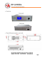
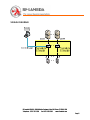
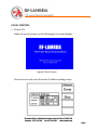
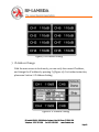
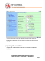
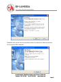
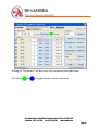
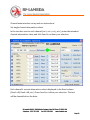
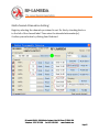
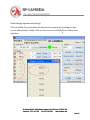
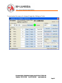
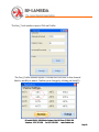
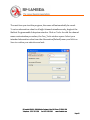
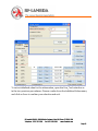
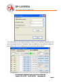
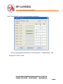
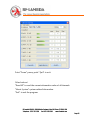
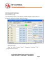
Model No: RFAS8810 8 IN 8 OUT Programmable Attenuator Subsystem RF-Lambda USA LLC. 6860 N Dallas Parkway, Suite 200, Plano, TX 75024, USA Telephone: (972) 767-5998 Fax: (972) 499-1302 www.rflambda.com Page 1 CONTENTS FEATURES ....................................................................................................... 3 SIGNAL DIAGRAM .......................................................................................... 5 SPECIFICATIONS ........................................................................................... 6 LOCAL CONTROL ........................................................................................... 7 1. 2. 3. 4. 5. 6. 7. Power On ............................................................................................................................ 7 IP Address Setting ............................................................................................................. 8 Remote / Local Setting ..................................................................................................... 8 Single-channel Attenuation Setting ................................................................................ 9 Multiple-channel Attenuation Setting ........................................................................... 11 All-Channel Attenuation Setting .................................................................................... 12 IP Address Change ......................................................................................................... 13 REMOTE CONTROL ...................................................................................... 14 1. 2. 3. 4. Port Configuration Software Installation ...................................................................... 14 Port Configuration Software Setting ............................................................................. 17 Operating Software Installation ..................................................................................... 22 Using the Software .......................................................................................................... 24 CUSTOM SCRIPT SETTINGS .................................................................... 36 ACCESSORIES.............................................................................................. 37 Ethernet and RS‐232 Command Information………………......……………… 38 RF-Lambda USA LLC. 6860 N Dallas Parkway, Suite 200, Plano, TX 75024, USA Telephone: (972) 767-5998 Fax: (972) 499-1302 www.rflambda.com Page 2 FEATURES 1. The RFAS8810 is a programmable, eight‐channel test subsystem, with a frequency range of 0.8 to 3 GHz and an attenuation range of 0 to 110 dB. 2. The unit runs on the Windows operating system, and is controlled through an RJ45 Ethernet interface by TCP/IP protocol. In order to control the attenuation of each channel, accessible by RS232 serial communication, users can write PC control programs in VBScript, under the RS232 serial communication protocol. 3. The programmable test subsystem can simplify test setups, such as handover, variable handover, and fade attenuator. Its most common use is in wireless communication signal tests, in the standard 19‐inch rack package, with high accuracy and stability. In addition to adjusting the unit remotely through LAN, RS‐232, or USB interface, you can also easily adjust it in local manual mode. With a large LCD display, keyboard, and knob, the sub‐system also has the capability of sending and receiving RS‐232 and/or Ethernet commands that you can format to meet your specific command requirements. RF-Lambda USA LLC. 6860 N Dallas Parkway, Suite 200, Plano, TX 75024, USA Telephone: (972) 767-5998 Fax: (972) 499-1302 www.rflambda.com Page 3 4. Panel view Front panel Back panel 5. Physical Dimensions (units = mm / inch) RF-Lambda USA LLC. 6860 N Dallas Parkway, Suite 200, Plano, TX 75024, USA Telephone: (972) 767-5998 Fax: (972) 499-1302 www.rflambda.com Page 4 SIGNAL DIAGRAM RF-Lambda USA LLC. 6860 N Dallas Parkway, Suite 200, Plano, TX 75024, USA Telephone: (972) 767-5998 Fax: (972) 499-1302 www.rflambda.com Page 5 SPECIFICATIONS Frequency Range: 0.8–3 GHz Impedance: 50 Ohms Attenuation Range: 0–110 dB in 1 dB steps VSWR: 1.5:1 maximum 1.3:1 typical Attenuation Accuracy: ±0.5 dB (<10 dB) ±1.0 dB (10–31 dB) ±1.5 dB (32–63 dB) ±2.5% dB (64–110 dB) Insertion Loss: 16 dB maximum RF Input Power: +30 dBm average Switching Speed: 2 us typical AC Supply: 100–240 VAC @ 47–63 Hz Manual Control: LCD display, keypad and rotary knob control Remote Control: Ethernet (RJ45), RS‐232, USB Remote Command Format: VBScript RF Connector: N female Operating Temperature: 0º C to +60º C Physical Size: 482.6 × 448 × 132.5 mm Weight: 8.6 Kg RF-Lambda USA LLC. 6860 N Dallas Parkway, Suite 200, Plano, TX 75024, USA Telephone: (972) 767-5998 Fax: (972) 499-1302 www.rflambda.com Page 6 LOCAL CONTROL 1. Power On When the power comes on, the following boot screen displays. Figure 1: Boot Screen After a few seconds you will see the IP address setting screen . Figure 2: IP Address Setting RF-Lambda USA LLC. 6860 N Dallas Parkway, Suite 200, Plano, TX 75024, USA Telephone: (972) 767-5998 Fax: (972) 499-1302 www.rflambda.com Page 7 2. IP Address Setting To modify the IP address, press the F1 key on the numeric keypad to open the address‐setting program (Figure 2). If you plan to use the default IP address, press F2 ship to " Remote / Local Setting" screen (Figure 3) For example: If you want to modify the IP address from 192.168.1.112 to 192.168.1.224, rotate the knob to position 112, and notice that the field is now highlighted in blue. Type “224”. Use the ESC key to cancel mistakes. After you finish, press F1 to save the setting. The remote/local setting screen will open. Figure 3: Remote / Local Setting 3. Remote / Local Setting To set the unit in remote mode, press F1; for local mode, press F2. After you make your selection, the main screen will open in the selected mode (local mode has black type, remote mode has a blue type). See Figure 4. In the main screen, press F1 to toggle between local and remote modes. In the local mode (only), press F2 to advance to the channel‐setting screen, and F3 for the IP address‐setting screen. In the remote mode, only the F1 key is functional. RF-Lambda USA LLC. 6860 N Dallas Parkway, Suite 200, Plano, TX 75024, USA Telephone: (972) 767-5998 Fax: (972) 499-1302 www.rflambda.com Page 8 Figure 4: Main Screen 4. Single‐channel Attenuation Setting As just mentioned, pressing F2 while in local mode on the main screen advances the system to the channel‐setting screen (Figure 5). To make a single channel selection, press F1. Rotate the knob to select a channel, indicated by an asterisk (*) See Figure 6. Press ENTER to return the main screen, and the color of active channel will change from black to blue. There are two ways to set the attenuation value. One way is through the keyboard. For example, to set 45 dB, enter “45”, then press ENTER to set the active channel attenuation (Figure 7). If you make a mistake, press ESC to undo the last entry. The second method is using the knob. The attenuation in the active channel will increase by rotating the knob clockwise, and decrease by rotating it counterclockwise. Set the attenuation by pressing the knob slightly. RF-Lambda USA LLC. 6860 N Dallas Parkway, Suite 200, Plano, TX 75024, USA Telephone: (972) 767-5998 Fax: (972) 499-1302 www.rflambda.com Page 9 Figure 5: Channel setting Figure 6: Single‐Channel Setting RF-Lambda USA LLC. 6860 N Dallas Parkway, Suite 200, Plano, TX 75024, USA Telephone: (972) 767-5998 Fax: (972) 499-1302 www.rflambda.com Page 10 Figure 7: Attenuation Setting 5. Multiple‐channel Attenuation Setting With the main screen in local mode, press F2 to advance to the channel‐ setting screen. To make a multiple‐channel selection from the channel‐ setting screen, press F2 (Figure 8). As for a single‐channel selection, turn the knob to align the asterisk with an intended channel, and then press the knob slightly to select the channel. (Pressing the knob twice will cause the symbol to disappear, meaning no channel is selected.) In the same way, select the rest of the channels for which you intend to adjust the attenuation, and press ENTER to confirm your multiple selection. The display returns to the main screen, with the selected channels shown in blue. As with the single‐channel attenuation adjustment, there are two ways to set the attenuation value: through the keyboard, and by using the knob. Set the attenuation by pressing the knob slightly. RF-Lambda USA LLC. 6860 N Dallas Parkway, Suite 200, Plano, TX 75024, USA Telephone: (972) 767-5998 Fax: (972) 499-1302 www.rflambda.com Page 11 Figure 8: Multi‐channel Setting 6. All‐Channel Attenuation Setting With the main screen in local mode, press F2 to advance to the channel‐ setting screen. To select all channels from the channel‐setting screen, press F3 (Figure 9). Return to the main screen, and notice that all channels are displayed in blue (Figure 9), indicating their status as available for adjustment. As with the single‐ and multi‐channel attenuation adjustment, there are two ways to set the attenuation value: through the keyboard, and by using the knob. Set the attenuation by pressing the knob slightly. RF-Lambda USA LLC. 6860 N Dallas Parkway, Suite 200, Plano, TX 75024, USA Telephone: (972) 767-5998 Fax: (972) 499-1302 www.rflambda.com Page 12 Figure 9: All‐Channel Setting 7. IP Address Change With the main screen in local mode, you can verify the current IP address, and change the IP address by pressing F3 (Figure 10). For further instruction, please see Section 2: IP Address Setting. Figure 10: IP Address Setting RF-Lambda USA LLC. 6860 N Dallas Parkway, Suite 200, Plano, TX 75024, USA Telephone: (972) 767-5998 Fax: (972) 499-1302 www.rflambda.com Page 13 REMOTE CONTROL 1. Port Configuration Software Installation Begin by installing the serial port server driver. Open the NE‐4110S folder, and click “neadm_setup_Ver2.11_Build_07082213.exe” to start the installation. Click the “Next” button. The following window opens: RF-Lambda USA LLC. 6860 N Dallas Parkway, Suite 200, Plano, TX 75024, USA Telephone: (972) 767-5998 Fax: (972) 499-1302 www.rflambda.com Page 14 Click the “Next” button. The following window opens: RF-Lambda USA LLC. 6860 N Dallas Parkway, Suite 200, Plano, TX 75024, USA Telephone: (972) 767-5998 Fax: (972) 499-1302 www.rflambda.com Page 15 Click the “Next” button. The following window opens: Click “Install” to open the installation window. RF-Lambda USA LLC. 6860 N Dallas Parkway, Suite 200, Plano, TX 75024, USA Telephone: (972) 767-5998 Fax: (972) 499-1302 www.rflambda.com Page 16 After the installation is complete, the following window opens. Click “Finish” to finalize the installation. 2. Port Configuration Software Setting Open “Network Enabler Administrator.” RF-Lambda USA LLC. 6860 N Dallas Parkway, Suite 200, Plano, TX 75024, USA Telephone: (972) 767-5998 Fax: (972) 499-1302 www.rflambda.com Page 17 To modify the IP address (with the unit connected to the PC via parallel cable), begin by opening the Configuration menu and selecting Broadcast Search. The system will search for all available subsystems, and display a search screen, as seen immediately below. RF-Lambda USA LLC. 6860 N Dallas Parkway, Suite 200, Plano, TX 75024, USA Telephone: (972) 767-5998 Fax: (972) 499-1302 www.rflambda.com Page 18 Double‐click on the system whose IP address you want to modify (NE‐4110S, in the illustrated example) to open its IP Settings window. In the Configuration window, select the Network tab, check the Modify check box in the IP Address area, and enter the desired IP address. Follow the same procedure to modify the Netmask and/or Gateway addresses. RF-Lambda USA LLC. 6860 N Dallas Parkway, Suite 200, Plano, TX 75024, USA Telephone: (972) 767-5998 Fax: (972) 499-1302 www.rflambda.com Page 19 To confirm your selections, click OK. RF-Lambda USA LLC. 6860 N Dallas Parkway, Suite 200, Plano, TX 75024, USA Telephone: (972) 767-5998 Fax: (972) 499-1302 www.rflambda.com Page 20 Open Internet Explorer, and enter the unit’s IP address. From the Main Menu, open the Serial Settings folder, adjust the parameters as necessary, and click on Submit to confirm your selections. RF-Lambda USA LLC. 6860 N Dallas Parkway, Suite 200, Plano, TX 75024, USA Telephone: (972) 767-5998 Fax: (972) 499-1302 www.rflambda.com Page 21 From the Main Menu, open the Operating Settings folder, adjust the parameters as necessary, click on Submit to confirm your selections, and close IE. 3. Operating Software Installation Open the file, “8in8out Install,” and click on “setup.exe” to begin the installation. RF-Lambda USA LLC. 6860 N Dallas Parkway, Suite 200, Plano, TX 75024, USA Telephone: (972) 767-5998 Fax: (972) 499-1302 www.rflambda.com Page 22 Read the text on the screen, and click on Next to advance to the next screen. Do not restart the computer. RF-Lambda USA LLC. 6860 N Dallas Parkway, Suite 200, Plano, TX 75024, USA Telephone: (972) 767-5998 Fax: (972) 499-1302 www.rflambda.com Page 23 To finalize the installation, click on Finish. 4. Using the Software Open the application: Access Control Interface. Click on the icon, “8in8outProgrammableSubsystem.exe”, or choose Start All Programs 8in8out ProgrammableSubsystem.exe. Because of the test subsystem’s access to the LAN, the network computer can access this subsystem. Run “8 in 8 out Programmable Subsystem.exe” by following the prompts provided in the windows that open. When the subsystem window opens, enter “192.168.1.200” in the IP Address text box, and then click on Connect. RF-Lambda USA LLC. 6860 N Dallas Parkway, Suite 200, Plano, TX 75024, USA Telephone: (972) 767-5998 Fax: (972) 499-1302 www.rflambda.com Page 24 Clicking on “Disconnect” will disconnect the communication subsystem. Click either or to toggle between remote and local. RF-Lambda USA LLC. 6860 N Dallas Parkway, Suite 200, Plano, TX 75024, USA Telephone: (972) 767-5998 Fax: (972) 499-1302 www.rflambda.com Page 25 Channel main interface set‐up and use instructions: Set single‐channel attenuation values: In the text box next to each channel (ANT1, ANT2, ANT3, etc.), enter the intended channel attenuation value, and click Send to confirm your selection. Each channel’s current attenuation value is displayed in the Read column (Read 1 dB, Read 2 dB, etc.). Press Send to confirm your selection. The text will be cleared before the data. RF-Lambda USA LLC. 6860 N Dallas Parkway, Suite 200, Plano, TX 75024, USA Telephone: (972) 767-5998 Fax: (972) 499-1302 www.rflambda.com Page 26 Multi‐channel Attenuation Setting: Begin by selecting the channels you intend to set. Do this by checking the box to the left of the channel label. Then enter the intended attenuation(s). Confirm your selection by clicking Send Selected. RF-Lambda USA LLC. 6860 N Dallas Parkway, Suite 200, Plano, TX 75024, USA Telephone: (972) 767-5998 Fax: (972) 499-1302 www.rflambda.com Page 27 Road through operational settings: Click on Visible Port, and select the interface to operate by checking the box next to the interface’s label. Click on Save to save, and Exit(E) to confirm your selection. RF-Lambda USA LLC. 6860 N Dallas Parkway, Suite 200, Plano, TX 75024, USA Telephone: (972) 767-5998 Fax: (972) 499-1302 www.rflambda.com Page 28 To customize the name of a channel, begin by clicking on Tools. RF-Lambda USA LLC. 6860 N Dallas Parkway, Suite 200, Plano, TX 75024, USA Telephone: (972) 767-5998 Fax: (972) 499-1302 www.rflambda.com Page 29 The Frm_Tools window opens. Click on Profile. The Frm_Profile window opens. Use the text box next to the channel label to modify its name. Confirm your change by clicking on Save(S). RF-Lambda USA LLC. 6860 N Dallas Parkway, Suite 200, Plano, TX 75024, USA Telephone: (972) 767-5998 Fax: (972) 499-1302 www.rflambda.com Page 30 The next time you start the program, the name will automatically be saved. To set an attenuation value for all eight channels simultaneously, begin at the 8in8out Programmable Subsystem window. Click on Tools. As with the channel name‐customization procedure, the Frm_Tools window opens. Select your intended attenuation value from the Attenuation(Default) menu, and click on Save to confirm your selection and exit. RF-Lambda USA LLC. 6860 N Dallas Parkway, Suite 200, Plano, TX 75024, USA Telephone: (972) 767-5998 Fax: (972) 499-1302 www.rflambda.com Page 31 To set an initialized value for the attenuation, open the Frm_Tools window as in the two previous procedures. Choose a value from the Initialized Value menu, and click on Save to confirm your selection and exit. RF-Lambda USA LLC. 6860 N Dallas Parkway, Suite 200, Plano, TX 75024, USA Telephone: (972) 767-5998 Fax: (972) 499-1302 www.rflambda.com Page 32 Save and return to the main interface, when in the "Settings" drop‐down list, select a channel, click on "Iinitiallze" later. In addition to the selected channel 5 (set value) , the other channels are 110 (maximum attenuation) . RF-Lambda USA LLC. 6860 N Dallas Parkway, Suite 200, Plano, TX 75024, USA Telephone: (972) 767-5998 Fax: (972) 499-1302 www.rflambda.com Page 33 Click "AutoScript" run into the automation interface. Set the appropriate parameters, the first point of "Application", and then point "start" to run. RF-Lambda USA LLC. 6860 N Dallas Parkway, Suite 200, Plano, TX 75024, USA Telephone: (972) 767-5998 Fax: (972) 499-1302 www.rflambda.com Page 34 Point "Pause" pause, point "Quit" to exit. Other buttons: "Read All" to read the current attenuation value of all channels. "About System" system‐related information. "Exit" to exit the program. RF-Lambda USA LLC. 6860 N Dallas Parkway, Suite 200, Plano, TX 75024, USA Telephone: (972) 767-5998 Fax: (972) 499-1302 www.rflambda.com Page 35 CUSTOM SCRIPT SETTINGS Run automation script: From the primary window, select Browse, and then navigate to the location of the VBScript. Begin the script by clicking on Run(R). Communication protocol can be written by python scripts custom Self Python script. Open the folder "python Demo", "Attenuator Control.py" This program has been tested. RF-Lambda USA LLC. 6860 N Dallas Parkway, Suite 200, Plano, TX 75024, USA Telephone: (972) 767-5998 Fax: (972) 499-1302 www.rflambda.com Page 36 ACCESSORIES 1.110V/ 220V power cable 1pcs 2.CD (driver, control software, user manual) 1pcs 3.User manual 4.Product certification 1pcs 1pcs RF-Lambda USA LLC. 6860 N Dallas Parkway, Suite 200, Plano, TX 75024, USA Telephone: (972) 767-5998 Fax: (972) 499-1302 www.rflambda.com Page 37 <CR> = carriage return <LF> = line feed Command must be terminated by carriage return and line feed. • Identification This command echoes back information and help information about the test system. Syntax: HX<CR><LF> Example: HX<CR><LF> System will return: >>RF‐Lambda Firmware Rev A! >>SA:Set attenuator value! >>RA:Get attenuator value! >>SS:Set switch value! >>RS:Get switch value! >>RI:Get the input port connected to any output port! >> It is used in a power divider system! >>RO:Get the output port connected to any input port! >> It is used in a power Combiner system! >>LO:Lock keyboard of the system!, >>LU:Unlock keyboard of the system!, >>RT:Restart system!, >>Enter "HX" and command without space to get more details! Notes: Command is not case sensitive. • Set Attenuator The set attenuator command is used to set the attenuation level of a specific attenuator. Syntax: SAx y<CR><LF> x = attenuator number y = attenuation level Example: SA11 20<CR><LF> Sets attenuation of attenuator #11 to 20dB. System will return: >>A11:20dB;<CR><LF> SA1 10;SA3 30<CR><LF> Sets attenuation of attenuator #1 to 10dB,#3 to 10dB. System will return: >>A1:10dB;A3:30dB;<CR><LF> SA1‐6 20<CR><LF> Sets attenuation of attenuator from #1 to #6 to 127dB. System will return: >>A1:10dB;A2:20dB ;A3:10dB;A4:20dB; <CR><LF> >>A1:10dB;A3:20dB;<CR><LF> RF-Lambda USA LLC. 6860 N Dallas Parkway, Suite 200, Plano, TX 75024, USA Telephone: (972) 767-5998 Fax: (972) 499-1302 www.rflambda.com Page 38 Read Attenuator The read attenuator command returns the attenuation setting for a specific attenuator. Syntax: RAx<CR><LF> x = attenuator number Example: RA11<CR> <LF> Reads attenuator #11 setting. System will return >>A11:20dB;<CR><LF> RA1;SA3<CR><LF> Reads attenuation of attenuator #1,#3 setting. System will return >>A1:10dB;A3:30dB;<CR><LF> RA1‐6<CR><LF> Reads attenuator from #1 to # 6 setting. System will return >>A1:10dB;A2:20dB ;A3:10dB;A4:20dB; <CR><LF> >>A1:10dB;A3:20dB;<CR><LF> • Set Switch The set switch command is used to set a switch to a specifi c port number. Syntax: SSx y<CR><LF> x = switch number y = port number Example: SS11 8<CR><LF> Sets switch #11 to port 8. System will return: >>S11:8;<CR><LF> SS1 4;SS3 8<CR><LF> Sets switch #1 to port4,#3 to port8. System will return: >>S1:4;S3:8;<CR><LF> SA1‐6 1<CR><LF> Sets switch from #1 to #6 to port 1. System will return: >>S1:1;S2:1;S3:1;S4:1;<CR><LF> >>S5:1;S6:1;<CR><LF> • Read Switch The read switch command returns the port setting for a specific switch. Syntax: RSx<CR><LF> x = switch number Example: RS11<CR> <LF> Read switch #11 setting. System will return >>S11:8;<CR><LF> RS1;SA3<CR><LF> Read switch #1,#3 setting. System will return >>S1:4;S3:8;<CR><LF> RS1‐6<CR><LF> Read switch from #1 to #6 setting. System will return >>S1:1;S2:1;S3:1;S4:1;<CR><LF> >>S5:1;S6:1;<CR><LF> RF-Lambda USA LLC. 6860 N Dallas Parkway, Suite 200, Plano, TX 75024, USA Telephone: (972) 767-5998 Fax: (972) 499-1302 www.rflambda.com Page 39 Read Input Get the input port connected to any output port! It is used in a power divider system! Syntax: RIx<CR><LF> x = output port Example: RI 1<CR> <LF> Get the input port connected to output #1! System will return >>RI1:1,3,5,8;<CR><LF> • Read Output Get the output port connected to any input port! It is used in a power Combiner system! Syntax: ROx<CR><LF> x = input port Example: RO 1<CR><LF> Get the output port connected to input #1! System will return >>RO1:1,3,5,8;<CR><LF> • Lock keyboard Lock keyboard of the system! Syntax: LO<CR><LF> Example: LO<CR><LF> System will return >>Keyboard is locked!<CR><LF> >>Keyboard is unlocked!<CR><LF> Restart system! Syntax: RT123ABC<CR><LF> Example: RT123ABC<CR><LF> System will return >>System will restart!<CR><LF> • Lock keyboard Unlock keyboard of the system! Syntax: LU<CR><LF> Example: LU<CR><LF> System will return • Reset system RF-Lambda USA LLC. 6860 N Dallas Parkway, Suite 200, Plano, TX 75024, USA Telephone: (972) 767-5998 Fax: (972) 499-1302 www.rflambda.com Page 40