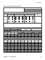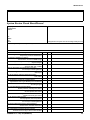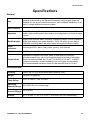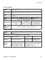
1
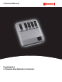
Technical Manual Touchpoint 4 4 Channel Gas Detector Controller TP4MAN Issue 3 Apr 06 (MAN0631) 2 Safety Safety Ensure that this Technical Manual is read and understand BEFORE installing/operating/ maintaining the equipment. This manual supports software revision 1.02 for the Common Module and 1.04 for the Channel Modules. Pay particular attention to Warnings and Cautions. All document Warnings are listed here and repeated where appropriate at the start of the relevant chapter(s) of this Technical Manual. Cautions appear in the sections/sub-sections of the document where they apply. WARNINGS Touchpoint 4 is designed for installation and use in indoor safe area non-explosive atmospheres. Installation must be in accordance with the recognized standards of the appropriate authority in the country concerned. Before carrying out any work ensure local regulations and site procedures are followed. Access to the interior of the controller, when carrying out any work, must only be conducted by trained personnel. Switch off and isolate the power supply to the controller when access is required. Take any necessary precautions to prevent false alarms. The detectors/sensors that the controller connects to may be used for gas detection in hazardous atmospheres. Refer to the individual detector/sensor instructions for their details. TP4MAN Issue 3 Apr 06 (MAN0631) 3 Information Information Honeywell Analytics can take no responsibility for installation and/or use of its equipment if this is not done in accordance with the appropriate issue and/or amendment of the Technical Manual. The reader of this Technical Manual should ensure that it is appropriate in all details for the exact equipment to be installed and/or operated. If in doubt, contact Honeywell Analytics for advice. The following types of notices are used throughout this Technical Manual: WARNING Identifies a hazardous or unsafe practice which could result in severe injury or death to personnel. Caution Note Identifies a hazardous or unsafe practice which could result in minor injury to personnel, or product or property damage. Identifies useful/additional information. Every effort has been made to ensure the accuracy of our documents, however, Honeywell Analytics can assume no responsibility for any errors or omissions in our documents or their consequences. Honeywell Analytics greatly appreciates being informed of any errors or omissions that may be found in the contents of any of our documents. For information not covered in this document, or there is a requirement to send comments/ corrections about this document, please contact Honeywell Analytics. Honeywell Analytics reserve the right to change or revise the information supplied in this document without notice and without obligation to notify any person or organization of such revision or change. If information is required that does not appear in this document, contact the local distributor/agent or Honeywell Analytics. TP4MAN Issue 3 Apr 06 (MAN0631) 4 Contents Contents Safety 3 Information 4 Introduction Enclosure Common Module Channel Module General 7 8 8 8 9 Installation Location Dimensions Enclosure Rear Panel Detail Mounting Bracket Mounting Controller Components Power Cabling Wiring Common Module Wiring Channel Module Wiring Generic Gas Detector Connections Maximum Cable Lengths 10 10 11 11 12 12 13 13 15 15 16 17 20 26 27 Operation Powering Up Information on the Displays Control Buttons Using Menus Displaying Menus Navigating Menus Accepting Menu Choices Cancelling Operations/Choices Alarms Common Module Status Indications Alarms Menus 29 29 30 31 32 32 32 32 32 33 34 34 37 37 TP4MAN Issue 3 Apr 06 (MAN0631) 5 Contents Channel Module Status Indications Alarms Menus 38 38 43 43 User Settings Common Module Settings Event History RS485 Relay Action Time and Date Power Source Channel Settings Gas Units and Range Zero and Span Alarm Levels and Relay Action Channel Address Common Module Default Configuration Channel Module Default Configuration mV input detector 4-20 mA input detector 44 45 46 46 47 49 50 51 52 52 54 55 55 55 56 56 Commissioning 3-wire mV Bridge 2-Wire 4-20 mA Sink 3-wire 4-20 mA Source 57 57 59 60 Maintenance General Maintenance Troubleshooting System Configuration Check Sheet System Review Check Sheet/Record 61 61 62 63 64 Parts Touchpoint 4 Controllers Accessories Spares 65 65 66 66 Specifications General Environmental Common Module Channel Module 67 67 67 68 68 Warranty 70 TP4MAN Issue 3 Apr 06 (MAN0631) 6 Introduction Introduction Touchpoint 4 is a self-contained 4 channel gas detector controller for use in indoor safe areas. It is designed for use with the Zareba range of Flammable, Toxic and Oxygen gas detectors — Sensepoint, Sensepoint Plus and Sensepoint Pro. For each channel one of two types of control unit is available: • mV version — for 3-wire mV flammable gas detectors, e.g. Sensepoint Flammable detector • 4-20 mA version — for 2 and 3-wire 4-20 mA gas detectors, e.g. Sensepoint Toxic and Oxygen detectors, Sensepoint Plus and Sensepoint Pro detectors Touchpoint 4 is wall mounted and displays gas concentration, alarm, fault and status information via backlit LCDs and LEDs, together with a built-in audible alarm. A keypad, located beneath a panel under each display, enables user adjustment. Access Panel (removed for clarity) Channels 1 to 4 Display Modules 8-wire Terminal Block Controls Access Panel 3-wire Terminal Block Enclosure Terminal Module 20-wire Terminal Block On/Off Switch & Fuse Terminal Module 3-wire Terminal Block Cable/Conduit Entry (11 off) The controller is AC and/or DC powered. Up to four gas detectors are connected to the unit via any of 4 channels, each featuring a terminal module that also provides connections for relay and repeated 4-20 mA signals. The controller features powered audio/visual outputs and also a remote reset. The controller can be monitored via a serial communication link. TP4MAN Issue 3 Apr 06 (MAN0631) 7 Introduction Enclosure The rigid steel enclosure houses a Common Module and up to four Channel Modules, each featuring a Display Module and a Terminal Module. It has integral mounting hooks on the rear for fitting to a supplied mounting plate. The base of the box has a removable plate with multiple cable/conduit knock-out entries to enable wiring to all the terminal modules. A hinged panel below the display modules accesses the terminal modules. For mechanical installation details see page 13. Common Module This part of the controller features a Display Module and a Terminal Module. The Display Module provides a common point for alarm/fault display and management, and provides configuration control and displays common system functions. It features an LCD screen and 4 buttons, three behind a Controls Access Panel, that are used to navigate through an integral menu system to set up the common controller settings, and view various functions. The Terminal Module provides a connection point for power and signal wiring, and features the following: • • • 20-wire terminal block for common relay output signals, RS485 data, remote relay outputs, remote reset, remote audible/visual outputs and battery supply/backup power, see page 16 3-wire terminal block mains power, see page 16 power on/off toggle switch and replaceable fuse • 3 relays for alarms and faults For electrical installation details see page 17. Channel Module Caution The type of Channel Module fitted is specific to the type of attached gas detector and must NOT be used with other detector types. Either of the following types of Channel Module can be fitted to any of the controller’s four channel positions: • mV module • 4-20 mA module Each of these types of Channel Module consists of a specific type of Display Module and Terminal Module. Both types allow easy set up and configuration/calibration of the channel to the attached gas detector. TP4MAN Issue 3 Apr 06 (MAN0631) 8 Introduction The Display Module features an LCD screen, to display gas concentrations and ranges, settings, alarms and faults, and 4 buttons, three behind a Controls Access Panel, that are used to navigate through an integral menu system to set up the channel/detector settings and view a history record of channel status, e.g. alarms, etc. The Terminal Module provides the connection point for channel signals, and features the following: • 8-wire terminal block for the gas detector signals, relay outputs, and repeated 4-20 mA signal, see page 16 • 2 relays for alarms For electrical installation details see page 20. General This Technical Manual provides all the information necessary to install, commission, operate and maintain the controller in conjunction with the Zareba range of gas detectors. It consists of the following chapters: • • • • • • • • Introduction Installation, see page 10 Operation, see page 29 User Settings, see page 44 Commissioning, see page 57 Maintenance, see page 61 Parts, see page 65 Specification, see page 67 TP4MAN Issue 3 Apr 06 (MAN0631) 9 Installation Installation WARNINGS Touchpoint 4 is designed for installation and use in indoor safe area non-explosive atmospheres. Installation must be in accordance with the recognized standards of the appropriate authority in the country concerned. Before carrying out any work ensure local regulations and site procedures are followed. Access to the interior of the controller, when carrying out any work, must only be conducted by trained personnel. Switch off and isolate the power supply to the controller when access is required. Take any necessary precautions to prevent false alarms. The detectors/sensors that the controller connects to may be used for gas detection in hazardous atmospheres. Refer to the individual detector/sensor instructions for their details. This chapter provides the following information about installing Touchpoint 4: • where to locate the controller, its dimensions and how to mount it • how to access the interior of the controller, see page 13 • cabling and wiring, see page 15 Note It is recommended that a local fused power feed spur, with lockout switch, is used. Earth/Ground loops or poor screening are the most common cause of false alarms. Proper installation, using appropriate earth techniques improves: • resistance to radio frequency interference (RFI), e.g. mobile phones and walkietalkies • resistance to induced signals from magnetic fields (EMC), e.g. high power cables and switch gear. Location Touchpoint 4 can only be installed in indoor safe areas. Refer to International codes of practice, e.g. National Electrical Code (NEC) or Canadian Electrical Code (CEC), where applicable, for guidance when installing. Ensure that the maximum distance from the controller to the detector is within specification. Locate the bracket so that when the controller is fitted to it there is: • • • • easy access to it a clear view of the controller‘s displays (normally eye level), check for national/ local regulations regarding the viewing of displays enough space to open the enclosure’s access panels, for cabling, maintenance, adjustments, etc. enough space for cable or conduit access to the bottom of the enclosure TP4MAN Issue 3 Apr 06 (MAN0631) 10 Installation Follow the advice of: • experts having specialist knowledge of gas detection and control systems • experts having knowledge of the process plant system and equipment involved • safety and engineering personnel Always record the location of the detectors connected to the controller. Dimensions Enclosure Note Diagram not to scale TP4MAN Issue 3 Apr 06 (MAN0631) 11 Installation Rear Panel Detail Mounting Hooks Mounting Bracket 172.0 mm (6.8”) 86.0 mm (3.4”) 228.0 mm (9.0”) 198.0 mm (7.8”) 268.0 mm (10.6”) Thickness = 5.3 mm (0.2”) max. TP4MAN Issue 3 Apr 06 (MAN0631) 12.0 mm (0.5”) Note Diagram not to scale. 12 Installation Mounting Touchpoint 4 is supplied with a mounting bracket that fits onto a suitable wall. The controller is then hooked onto the bracket. The previous diagrams show dimensions for the enclosure and the bracket. Fit the bracket to a flat, firm surface, e.g. wall, suitable for the controller’s size and weight. 1 Mark out and drill holes for the mounting bracket screws. Use the mounting bracket as a template for the position of the holes. Use 4 off M3.5 x25 screws 2 Fix the bracket securely to the wall. When mounting Touchpoint 4 ensure the screws do not catch on the back of the controller when it is fitted onto the bracket. 3 With the bracket secure, locate and then lower Touchpoint 4 onto it. Ensure the two top and single bottom hooks on the back of the unit engage properly in the mounting bracket slots. Controller Components z TP4MAN Issue 3 Apr 06 (MAN0631) 13 Installation This procedure describes how to access the components inside the controller. 1 Loosen the single screw securing the Terminal Module Access Panel. 2 Push down on the finger grips located at the top of the panel. See previous diagram. 3 Slide the panel down to release it. 4 Pull the panel outward. Pull it until the door is approximately at a right-angle to the enclosure. 5 Push the panel inward toward the enclosure. This locks it in the open position and provides two-handed access to the Terminal Modules. Terminal Module Common Module Terminal Plastic Cover On/Off Switch 20-wire Terminal Block Fuse 3-wire Terminal Block Terminal Module Terminal Plastic Cover Channel Module 8-wire Terminal Block 3-wire Terminal Block TP4MAN Issue 3 Apr 06 (MAN0631) 14 Installation To access the connections on the terminal blocks, slide the clear plastic cover fitted over them off. The plastic cover can be completely removed if required. 6 After carrying out the procedures subsequently described close and secure the Terminal Module Access Panel with the screw. Caution Always ensure the Terminal Module Access Panel is replaced/ refitted after work is complete. Power Touchpoint 4 has an auto sensing power supply capable of operating between 85 and 265 Vac, 50/60Hz mains supply, and/or 19 to 30 Vdc. Honeywell Analytics recommend that the power to the controller is sourced from a locally fused circuit. This should have an isolation facility for maintenance purposes. The table on page 19 and the terminal block diagram following the table show the wiring for power to Touchpoint 4. Maximum power requirement for worst case detector configuration and relays activated is 160Wac and/or 63Wdc. Touchpoint 4 can accept signals from three types of detector. The table summarizes the types of detector compatible with the controller and the maximum power required. Type of detector Maximum Power Recommended Detector 2-wire 4-20 mA sink 500 mA (19 to 30 Vdc) Sensepoint Toxic and Oxygen 3-wire 4-20 mA source 500 mA (19 to 30 Vdc) 3-wire mV bridge Sensepoint Plus and Sensepoint Pro 2.9-3.5V, 200 mA, 0.7W (max) Sensepoint Flammable Cabling Touchpoint4 is designed for use in safe areas. Electrical installation should follow national guidelines using suitably approved cable and glands (M20 or 3/4"NPT) or conduit (3/4"NPT). Approved cable glands must accommodate a 360 degree termination of the EMI shield. Screened 0.5mm² (20AWG) to 2.5mm² (14AWG) cross sectional area cable should be used where appropriate to minimize unwanted effects from RF sources. 1.0 mm² is preferred. Wires can be either solid or stranded type. Ensure the cable gland is installed correctly and fully tightened. The enclosure has 11 knockouts in the base sized for both M20 and 3/4 in. NPT fittings. When running cabling to the unit consider conduit/cable weights to avoid any stress to the unit. The following diagrams show examples of how to earth-bond Steel Wired Armored (SWA) cable at enclosures. The same principles apply to conduit installations. These bonding techniques provide good RFI/EMC performance. To calculate the maximum cable run length from the controller to the detector see page 27. For RS485 signal wiring/protocol contact Honeywell Analytics for further details. TP4MAN Issue 3 Apr 06 (MAN0631) 15 Installation Neutral Live Earth AC Supply Star Ground/Earth Point Gas Detector +ve Signal -ve Wiring Caution An earth point is provided inside the controller. Ensure that all detector screens/armor are grounded at a single earth star point at the controller or detector — BUT NOT BOTH — to prevent false alarms due to earth loops. All electrical wiring connections are made via the Terminal Modules. Wire size from 0.5 to 2.5 mm2 (20 AWG to 14 AWG). 1.0 mm2 is preferred. TP4MAN Issue 3 Apr 06 (MAN0631) 16 Installation Always use suitable wiring techniques and crimps when terminating cable cores, especially if running two cores to a single terminal. Common controller connections are made at the Terminal Module for the Common Module. Connections for each detector are made at the Terminal Module for each Channel Module. Common Module Wiring Signals and DC power are connected to a 20-wire terminal block, and mains power is connected via a 3-wire terminal block on the Terminal Module, Terminal Module The following table lists the terminals and their functions and specifications. A B 4 1NC D+ 14 5 1C D- 15 6 1NO 16 RST1 7 2NC 17 RST2 8 2C A1 18 9 2NO A2 19 10 FNC F 20 11 FC VIS21 12 FNO 22 GND 13 DC+ DC-23 The next diagram shows the 20-wire terminal block layout with terminal identifiers. TP4MAN Issue 3 Apr 06 (MAN0631) 17 Installation Id. Name 4 N/O Contact NO 5 Common C 6 N/C Contact NC 7 N/O Contact NO 8 Common C 9 N/C Contact NC 10 N/O Contact NO 11 Common C 12 N/C Contact NC 13 DC Power +DC 14 D+ RS485 15 D- 16 R1 Remote Reset 17 R2 18 A1 Output A1 19 A2 Output A2 20 F Output F 21 Visible Output VIS 22 Power +VE 24V 23 DC Power -DC Function Input/ Output Specification Alarm Relay 1 Output 240 Vac, 3A max. Alarm Relay 2 Output 240 Vac, 3A max. Fault Relay Output 240 Vac, 3A max. DC supply/ battery back-up Input 19~30 Vdc, 63Wdc max RS485 Communication Link Input/ Output -7 to12V Remote Reset Input <12 Vdc Dedicated audio/ visual alarm drive Output 24 Vdc, <300 mA DC supply/ battery back-up Input 0 Vdc The following diagram shows the 3-wire mains terminal block layout with terminal identifiers. TP4MAN Issue 3 Apr 06 (MAN0631) 18 Installation 1 L 2 N 3 E The table lists the mains terminals and their functions and specification. Id. Name 1 Live L 2 Neutral N 3 Earth/Ground E Function Input/ Output Specification Power Supply Input 85 to 265 Vac, 50/60 Hz RS485 connection This link is for serial connection by RS485 link to other control equipment. The link settings can be configured for address and data rate, see page 46. For signal wiring contact Honeywell Analytics for further details. For the communication protocol manual, please visit our website at www.honeywellanalytics.com or contact one of our representatives. Remote reset These terminals are to connect an external reset button to Touchpoint 4. The button needs to operate in the same way as the Cancel button on the Display Module, i.e. normally open, momentary close to activate. 1 mm2 shielded cable recommended with a maximum cable length to the remote reset switch of 500 m (1640 ft). Dedicated audio/visual alarm drive + VE S3 S2 Audible Alarm S1 + VE - VE Visual Alarm (Red Flasher) Max. Supply = 3 x 450 mA Maximum Supply = 1350 mA @ 24 Vdc = 3 x 450mA = 1350mA @ 24VDC Common Module Common Module Dedicated Audible/Visual Alarm Drive NO S1 A1 18 NO S2 A2 S3 F AF 19 VIS VIS 21 Vdc +24 24VDC 22 0VDC NO NO 20 To Next Unit To Next Unit 1.5 AMP + 24VDC TP4MAN Issue 3 Apr 06 (MAN0631) 19 Installation Four audio/visual signals are output in addition to the common relays. They are for connection to remote audio/visual devices. The outputs are A1, A2, F with a common master alarm. Channel Module Wiring Detector power, signal, relay and repeated isolated 4-20 mA connections are made via 8-wire and 3-wire terminal blocks on each Terminal Module The following diagram shows the 8-wire terminal block layout with terminal identifiers 41NC4 8 4 2NC 51C 5 9 5 2C 61NO 6 10 6 2NO 7I+ 7 11 I-7 B A The table lists the terminals and their functions and specifications. Id. Name Function 4 Alarm Relay 1 N/O Contact 5 Alarm Relay 1 Common 6 Alarm Relay 1 N/C Contact NC 7 Isolated signal output +I 8 Alarm Relay 2 N/O Contact NO 9 Alarm Relay 2 Common 10 Alarm Relay 2 N/C Contact NC 11 Isolated signal output –I TP4MAN Issue 3 Apr 06 (MAN0631) NO C C Alarm Level 1 4-20 mA signal Alarm Level 2 4-20 mA signal Input/ Output Specification Output 240 Vac, 3A max. Output 240 Vac, 3A max. Output 240 Vac, 3A max. Output 0~22 mA Output 240 Vac, 3A max. Output 240 Vac, 3A max. Output 240 Vac, 3A max. Output 0~22 mA 20 Installation The next diagram shows the 3-wire detector power/signal terminal block layout with terminal identifiers. 1 2 3 + S - The table lists the detector power/signal terminals and their functions and specification. Id. Name 1 Power supply 2 Signal 3 Power supply Function + Gas Detector power and signal Input/ Output Output Signal Input - Output Specification 4-20 mA input module: 2-wire, 4-20 mA loop powered, or, 3-wire, 4-20 mA source Min guaranteed 19 Vdc, Input impedance: 100 Ohms mV input module: 3-wire, mV bridge self regulating supply voltage (subject to cable resistance) Maximum loop resistance: 100 Ohms Variable signal 0 Vdc Zareba Sensepoint Gas Detector Connections Touchpoint 4 is specifically designed for use with the Zareba Sensepoint range of gas detectors. The subsequent diagrams show connection details for these units. For further information about Zareba Sensepoint detectors refer to their individual user guides. TP4MAN Issue 3 Apr 06 (MAN0631) 21 Installation TP4MAN Issue 3 Apr 06 (MAN0631) 22 Installation TP4MAN Issue 3 Apr 06 (MAN0631) 23 Installation TP4MAN Issue 3 Apr 06 (MAN0631) 24 Installation TP4MAN Issue 3 Apr 06 (MAN0631) 25 Installation Generic Gas Detector Connections The following diagrams show generic installation connections for other gas detectors. 3-Wire mV Detector 3-Wire 4-20 mA Detector Controller +ve Signal -ve Detector 1 1 2 2 3 3 TP4MAN Issue 3 Apr 06 (MAN0631) +ve Signal -ve 26 Installation 2-Wire 4-20 mA Detector Controller +ve Signal Detector 1 1 2 2 3 3 +ve Signal RL -ve Maximum Cable Lengths To calculate the maximum cable run length from power source to the detector refer to the following example diagram and formula. Rloop = (Vcontroller — Vdetector min) / Idetector Maximum cable run length = Rloop / cable per metre resistance where: Rloop = Vcontroller = maximum working cable run resistance maximum available supply voltage at controller Vdetector min = minimum voltage at which the connected sensor can operate (sensor dependent, see individual sensor technical manual/data sheets) Idetector = sensor maximum drawn current (sensor dependent, see individual sensor technical manual/data sheets) TP4MAN Issue 3 Apr 06 (MAN0631) 27 Installation Detector Vsupply Cable run Imax Controller Signal Vs ensor Rl 0V TP4MAN Issue 3 Apr 06 (MAN0631) 28 Operation Operation WARNINGS Access to the interior of the controller, when carrying out any work, must only be conducted by trained personnel. Switch off and isolate the power supply to the controller when access is required. Take any necessary precautions to prevent false alarms. Once powered and connected properly with the gas detector(s), Touchpoint 4 displays gas concentration, alarm, fault and status information on each Channel Module, and shows channel and system related information on its Common Module. Management of the overall system and individual channels is via menus and control buttons. This chapter provides operational information about the following: • powering-up • information on the displays, see page 30 • control buttons, see page 31 • using menus, see page 32 • Common Module options, see page 34 • Channel Module options, see page 38 Powering Up Touchpoint 4 is mains AC and/or DC powered. Power up/power down the controller using the ON/ OFF switch located on the Terminal Module, as follows. 1 Access the interior of the controller. See page 13. On/Off Switch & Fuse 2 Switch on Touchpoint 4. Use the On/Off switch on the Common Module. The controller is now in normal operation. Note After switching on or off always close the access panel. TP4MAN Issue 3 Apr 06 (MAN0631) 29 Operation Information on the Displays At switch on: • all display icons/text/numbers/symbols on the Common Module are lit • all LEDs on the Common Module are lit • the alarm buzzer sounds for 1.0 seconds. This sequence repeats twice and is the controller’s self-test procedure. 1 2 3 4 The Common Module display then shows: • • local time and date power LED indicator lit ALARM POWER FAULT ALARM POWER FAULT 2 4 The Common Module then tries to communicate with any connected individual Channel Module to show the number of Channel Module’s (1 - 4) connected 1 1 3 The controller then begins normal operation. ALARM POWER FAULT ALARM POWER FAULT Simultaneously all the icons on the display of each of the Channel Modules come on for 1 second. They then show a warm-up count down from C180 (3 minutes) to C000. To skip the warm-up sequence press the channel’s Cancel button for 3 seconds. After completing the warm-up the individual channels start to communicate with the Common Module. TP4MAN Issue 3 Apr 06 (MAN0631) 30 Operation Control Buttons The control buttons for the Common Module and each Channel Module are located beneath an access panel underneath their displays. To access the buttons carry out the following procedure: 1 Access the controller interior. See page 13. Note None of the Control Buttons Access Panels can be opened until access is made. 2 Push down on the finger grip located at the bottom of the Control Buttons Access Panel. See the subsequent diagram and the diagram on page 13. 3 Slide the panel down to release it. The panel springs upward and is held in the open position. This provides access to the buttons. Control AccessPanel Panel ControlButtons Buttons Access (removed (removedfor for clarity) clarity) Cancel Button Cancel Button Up Button Button Up OK Button Button OK Down Button Down Button The four control buttons provide the following functions. Button Function In Text Navigates up through menus and lists and is used to select (highlight) Up a menu option. Also used to increment values, e.g. range. X Navigates down through menus and lists and is used to select (highlight) a menu option. Also used to decrement values. Down Enters a menu function. Saves a user setting. OK Exits/cancels the current screen/option and returns to the previous screen/option. Acknowledges alarm/fault. Cancel With no gas event reported, press the button once to put the controller through it self-test routine, see page 30. The results of these actions are displayed on the associated display. TP4MAN Issue 3 Apr 06 (MAN0631) 31 Operation Using Menus Both the Common Module and each Channel Module use a menu system for configuration/ control that is displayed/navigated in the same way. Displaying Menus Press the and — Up and Down — control buttons at the same time. The Common Module shows the Event History menu icon flashing. Each Channel Module displays 000 in the gas reading position and the Gas Units/Range menu icon flashes. Navigating Menus 1 Press either the or — Up or Down — control buttons. This steps through the menu choices until one is selected. The associated icon flashes. 2 Press the — OK — control button to enter the selected menu. Accepting Menu Choices Press the — OK — control button. This saves the selection/value and moves to the next step. Cancelling Operations/Choices To cancel operations/choices: Press the X — Cancel — button. This returns to the previous menu level, setting, etc. Pressing Cancel again returns to normal operation. Note The system automatically returns to normal operation if no buttons are pressed for more than 30 minutes. For details of the Common Module menu see page 37. For details of the Channel Module menu see page 43. To change user settings/configuration using the menus and control buttons see page 44. TP4MAN Issue 3 Apr 06 (MAN0631) 32 Operation Alarms This section describes how detector events are shown at the Common Module and the Channel Module, and how to respond to them. All channel alarms and faults are monitored by the Common Module and can be acknowledged/ reset there. When any detector event occurs, e.g. Alarm 1, Alarm 2 or Fault, the related Channel Module reports this as follows: • the status icon for the type of event flashes, e.g. • the LED for the type of event flashes, e.g, • the channel’s audible alarm sounds — for Alarm 1 — ALARM At the same time the Common Module reports events as follows: • • the audible alarm sounds continuously the channel number, with the event condition, is highlighted by a flashing square around it, e.g 1 — for channel number 1 • the LED for the type of event flashes, e.g, • the corresponding relays/outputs are activated — ALARM To acknowledge/accept any alarm press the Cancel button on the Common Module. This causes: • • • the Common Module audible alarm to be silenced the related icons and LEDs on the Common Module change from flashing to steady the icons and LEDs on the relevant Channel Module change from flashing to steady The alarm can be acknowledged at the individual Channel Module by pressing its Cancel button but, although the alarm/fault LED becomes steady there, the audible alarm and event LED at the Common Module continue. Pressing the Cancel button again, silences the Common Module audible alarm and turns off all the related icons, outputs and LEDs. This resets the alarm/fault. TP4MAN Issue 3 Apr 06 (MAN0631) 33 Operation Common Module Caution Gas events occurring at detectors while the Common Module is in the menu mode are not reported there. The Channel Module continues to monitor gas detector events and report them. The Display Module on the Common Module provides a graphical user interface that, during normal operation shows: • common system status information • individual Channel Module alarm information • the time/date An audible alarm sounds whenever an abnormal event is detected, e.g. alarm, fault, etc. Alarms can be acknowledged/reset from the Common Module. The display also features a set of menus accessed and controlled via the set of four buttons below the display (3 are hidden under a panel), see page 31 and page 43. Three LEDs below the screen indicate status information - power on (green), gas alarm (red) and fault (amber). The history of the recorded events for each Channel Module can be viewed to show time/date of alarms, faults and power on/off. The display shows the alarm/ fault status of each channel, configuration mode, controller address, and current date and time. LCD Local Address, Alarms Total History Records Alarms and Fault, Power On/Off Relay Act/Reset Menu Icons The diagram shows the display layout. The meaning of the menu icons is explained on page 37. Alarm/Fault Status Active Channel Number Indicator - Frame Shows Status 1 2 3 4 Date Month, Year, Day Hour, Time Minute (24 hour clock) Status Indications Typical display indications and default relay status for a particular operational state are shown in the following examples. TP4MAN Issue 3 Apr 06 (MAN0631) Status LEDs ALARM POWER FAULT 34 Operation Status Operational State Display Normal operation 1 2 ALARM 3 POWER 2 ALARM Key: 3 POWER Relays Off Alarm Relay 1 de-energized Alarm Relay 2 de-energized Fault relay energized (default) On Alarm Relay 1 energized Alarm Relay 2 de-energized Fault relay energized 4 Audio/Visual Output — FAULT Alarm 1 Channel 1 1 Audible Alarm 4 A1, VIS FAULT LED on LED off LED flashing Alarm 1, A1, flashing (and/or A2, and/or F may flash) TP4MAN Issue 3 Apr 06 (MAN0631) 35 Operation Status Operational State Audible Alarm Display Alarm 2 Channel 2 1 2 ALARM 3 POWER 2 ALARM Key: 3 POWER On Alarm Relay 1 energized Alarm Relay 2 energized Fault relay energized On Alarm Relay 1 de-energized Alarm Relay 2 de-energized Fault relay de-energized 4 A2, VIS FAULT Detector Fault - Channel 3 1 Relays Audio/Visual Output 4 F VIS FAULT LED on LED off LED flashing Alarm 1, A1, flashing (and/or A2, and/or F may flash) TP4MAN Issue 3 Apr 06 (MAN0631) 36 Operation Status Operational State Display Power Fault 1 2 ALARM Key: 3 POWER Audio/Visual Output Audible Alarm Relays On Alarm Relay 1 de-energized Alarm Relay 2 de-energized Fault relay de-energized 4 F VIS FAULT LED on LED off LED flashing Alarm 1, A1, flashing (and/or A2, and/or F may flash) Alarms Common Module alarms, and how to deal with them, are described on page 33. Menus The Common Module has 5 menu options for configuring/controlling the system. They are represented on the display by the icons described in the following table. Menu Description Function More information View Event History Check the time/date of each alarm and power on/off See page 46 RS485 Communications Set the controller’s address and baud rate See page 46 Set relay actions Set relays to energized or deenergized, and latching or nonlatching See page 47 Set time and date Set the real-time clock on the controller See page 49 Choose power source Set power source to AC, DC or both See page 50 TP4MAN Issue 3 Apr 06 (MAN0631) 37 Operation Channel Module Caution Gas events occurring at the detector while the Channel Module is in the menu mode are not reported at the Channel Module or Common Module. The Channel Module features a user interface that, during normal operation, shows gas reading information, and also channel fault and information messages. It displays channel status and configuration information for the channel via a menu accessed and controlled via four buttons (3 are hidden) below the display, see page 31 and page 43. An audible alarm sounds whenever a channel event occurs, e.g. gas alarm, fault, etc. 3 LEDs below the screen indicate channel status information - power on (green), gas alarm (red) and fault (amber). Each channel’s alarms and faults are output to the Common Module where they are monitored and where common alarms are invoked. The display screen on each Channel Module shows the gas concentration (both graphically and numerically), range, units, alarm/fault status, and configuration mode. The diagram shows the display layout. The meaning of the menu icons is explained on page 43. Status Indications Typical display indications and default relay status for a particular operational state are shown in the following examples. TP4MAN Issue 3 Apr 06 (MAN0631) LCD Units Range Bar Graph Gas Reading/ Value Alarm/Fault Status Menu Icons Status LEDs ALARM POWER FAULT 38 Operation Status Operational State Audible Alarm Display Normal operation 000 Off Outputs Relays Alarm Relay 1 de-energized Alarm Relay 2 de-energized Fault relay energized (default) 4-20 mA (for 2000 ppm Comms. range) 4 mA Alarm set point indicators (bars) flash ALARM POWER FAULT Alarm 1 Key: On Alarm Relay 1 energized Alarm Relay 2 de-energized Fault relay energized 10 mA A1 LED on LED off LED flashing Alarm 1, A1, flashing (and/or A2, and/or F may flash) TP4MAN Issue 3 Apr 06 (MAN0631) 39 Operation Status Operational State Audible Alarm Display Outputs Relays 4-20 mA (for 2000 ppm Comms. range) Alarm 2 On Alarm Relay 1 energized Alarm Relay 2 energized Fault relay energized 15.3 mA A1 & A2 Greater than full scale alarm On Alarm Relay 1 energized Alarm Relay 2 energized Fault relay energized 22 mA A1 & A2 ALARM Key: POWER FAULT LED on LED off LED flashing Alarm 1, A1, flashing (and/or A2, and/or F may flash) TP4MAN Issue 3 Apr 06 (MAN0631) 40 Operation Status Operational State Audible Alarm Display Deadband (negative drift <5%) ALARM POWER Key: POWER Relays 4-20 mA (for 2000 ppm Comms. range) On Alarm Relay 1 de-energized Alarm Relay 2 de-energized Fault relay energized 4 mA On Alarm Relay 1 de-energized Alarm Relay 2 de-energized Fault relay de-energized 2.5 - 3.2 mA FAULT Fault (negative drift >5%) ALARM Outputs F FAULT LED on LED off LED flashing Alarm 1, A1, flashing (and/or A2, and/or F may flash) TP4MAN Issue 3 Apr 06 (MAN0631) 41 Operation Status Operational State Audible Alarm Display Fault (open/short circuit) ALARM POWER Relays 4-20 mA (for 2000 ppm Comms. range) On Alarm Relay 1 de-energized Alarm Relay 2 de-energized Fault relay de-energized 0 mA F - Alarm Relay 1 de-energized Alarm Relay 2 de-energized Fault relay energized 1.5 - 2.5 mA (normally 2.0 mA) F FAULT Inhibit Key: Outputs LED on LED off LED flashing Alarm 1, A1, flashing (and/or A2, and/or F may flash) TP4MAN Issue 3 Apr 06 (MAN0631) 42 Operation Alarms Channel Module alarms, and how to deal with them, are described on page 33. Menus The Channel Module has 4 menu options for configuring/controlling the channel. They are represented on the LCD screen by the icons shown in the following table, which describes them and explains what they are for. Menu Description Function More information Gas units/range settings Change gas units (%V/V, %LEL, kppm, ppm) and range See page 52 Set zero and span Calibrate the detector zero and span. See page 52 Set alarm levels and relay actions Change the gas levels at which alarms occur. Set relays to: latching or non-latching, See page 54 energized or de-energized, O2 only — also rising and falling Set channel address Set the channel address TP4MAN Issue 3 Apr 06 (MAN0631) See page 55 43 User Settings User Settings The controller is supplied pre-configured with factory defaults, see page 56. These can be used if suitable, or customized by the user to suit site requirements. This chapter describes: • how to carry out changes Note Some of these must be set up prior to commissioning, see page 57. • defaults for the common controller settings, see page 56 • defaults for the two types of Channel Module, see page 56 A menu system is used at the Common Module to change common controller settings, and also at each Channel Module to change the individual channel configuration. For the Common Module the chapter explains how to: • • • browse the controller’s event record, see page 46 set up the RS485 communication link, see page 46 set relay actions, see page 47 • set the real-time clock, see page 50 • set the power source, see page 51 For each Channel Module it explains how to: • set gas units and range, see page 53 • set zero and span, see page 54 • set alarm levels and relay actions, see page 55 • set the channel address, see page 56 Before performing any of the above actions refer to the procedures that explain how to use menus, see page 32. TP4MAN Issue 3 Apr 06 (MAN0631) 44 TP4MAN Issue 3 Apr 06 (MAN0631) Power Source Time/Date Relays RS485 History / / / Finished. Returns to Configuration Menu Select dC-1 (AC), dC-2 (AC&DC or dC-3 (DC) / Select day (1-31) Select hour (0-23) / X X Finished. Returns to Configuration Menu Select month (1-12) Select year (2000-2099) Select minutes (0-59) Select r 1-L (latching) or r 1-N (non-latching) Select r 1-E (energized) or r 1-d (deenergized) Repeat for Fault Finished. Returns to Configuration Menu Set Number of Enabled Channels (1 to 4) Set Baud Rate (1200, 4800, 4800, 9600, or 19200) Set Address (1 to 247) Repeat for A2 alarm level, energized and latching status Finished. Returns to menu selection screen Select next record. X to return to selection Selected event shows with Year, Date, and Time. / Select A1, A2, F or ON/OFF / / This table provides a summary of the common configuration options. For detailed step-by-step instructions for each menu see the subsequent sections. / Common Module Settings / User Settings 45 User Settings Event History This menu is to review up to 40 time and date records for alarms, faults (including channel number) and controller Power On/Off events. 1 Access the menu system and select the menu option. Press Up or Down. The icon flashes. 2 Press OK. The display shows the following information: • 40-xx - the record number out of 40 — latest shown first • the time and date of the event • A1, A2, F ON - alarm/fault activated • A1, A2, F OFF - latched alarm/fault accepted/reset, or nonlatched alarm/fault automatically reset • ON/OFF- power switched on/off • 1, 2, 3 or 4 - channel number The example shows that this is the 20th record out of 40 and the event is a Power ON at 10:06am on the 9th May 2004. 3 Select a different record using the Up/Down buttons. 4 Press Cancel. Goes to the event history record menu screen. 5 When record viewing is complete press Cancel. Returns to the menu selection screen. 6 Press Cancel. Returns controller to normal operation. Note Addressing/communications faults (between common and channel modules) are displayed in history by showing ALL channel indications (1 2 3 4) regardless of which channel had the fault. RS485 This menu is for setting the RS485 communication link settings. 1 Access the menu system and select the menu option. Press Up or Down. The icon flashes. 2 Press OK. The controller’s current address is displayed. TP4MAN Issue 3 Apr 06 (MAN0631) 46 User Settings 3 Use Up/Down to change the address. Between 001 and 247 (decimal). 4 Press OK to accept the change. The display changes to show the current baud rate. 5 Use Up/Down to change the baud rate. From 1200, 4800, 4800, 9600, or 19200. 6 Press OK to accept the change. The display changes to show the number of channels connected ot the common module. 7 Use Up/Down to change the number of channels fitted. 8 Press OK to accept the change. Returns to the menu selection screen. 9 Press Cancel. Returns controller to normal operation. Relay Action This section sets up the two alarm relays and the single fault relay. 1 Access the menu system and select the menu option. Press Up or Down. The icon flashes. TP4MAN Issue 3 Apr 06 (MAN0631) 47 User Settings 2 Press OK. The display changes to the A1 alarm relay action menu. The display shows either r 1-d (for relay 1 de-energized), or r 1-E (for relay 1 energized). 3 Use Up/Down to change the relay action. 4 Press OK to accept the change. The display changes to the relay latching or non-latching menu and shows either r 1-L (for relay 1 latching), or r 1-nL (for relay 1 nonlatching). 5 Use Up/Down to change the relay action. The following diagram shows the effect of latching or non-latching relays. Press Cancel button Gas Reading Press Cancel button Alarm Point Alarm Output Operation (Latching) Alarm Output Operation (Non-Latching) Audible alarm can be silenced with gas present If gas rises again then Audible Alarm re-activates Audible Alarm Flashing visual indicators show alarm has occurred and Cancel not pressed 6 Visual alarm not cleared until gas alarm has cleared and Cancel is pressed Visual indicators stop flashing and go steady when Cancel pressed but gas still present Press OK to accept the change. The display now changes to the current A2 alarm relay action menu. 7 Change A2 relay settings as for relay A1. TP4MAN Issue 3 Apr 06 (MAN0631) 48 User Settings 8 Press OK to accept the changes. The display now changes to the F fault relay settings. 9 Change F relay settings as for relay A1. Change the settings as for relay A1, see step 3 to step 6. 10 When settings are complete press OK. Returns to the menu selection screen. 11 Press Cancel. Returns controller to normal operation. TP4MAN Issue 3 Apr 06 (MAN0631) 49 User Settings Time and Date This menu sets the controller’s real-time clock. 1 Access the menu system and select the menu option. Press Up or Down. The icon flashes. 2 Press OK. At the bottom of the display the current selected year flashes. 3 Use Up/Down to change the year. Between 2002 and 2099. 4 Press the OK button to accept the change. The display changes to a flashing display of the current month setting. 5 Use Up/Down to change the month. Between 1 and 12. 6 Press OK to accept the change. The display changes to a flashing display of the current day. 7 Use Up/Down to change the day. Between 1 and 31. 8 Press OK to accept the change. The display changes to a flashing display of the current time (hours). 9 Use Up/Down to change the hours. Between 00 and 23. 10 Press OK to accept the change. The display changes to a flashing display of the current time (minutes). 11 Use Up/Down to change the minutes. Between 00 and 59. 12 Press OK. The display returns to the menu selection screen. 13 Press Cancel. Returns controller to normal operation. TP4MAN Issue 3 Apr 06 (MAN0631) 50 User Settings Power Source This menu programs Touchpoint 4 for the type of available power source(s). The controller can be set to any of three different power supply modes. 1 Access the menu system and select the menu option. Press Up or Down. The icon flashes. 2 Press OK. The display shows one of the following power modes: • dC-1 — AC only power supply • dC-2 — AC and DC power supplies • dC-3 — DC only power supply 3 Note 4 Use Up/Down to select the required power configuration. If the system is powered by an AC supply, only dC-1 or dC-2 should be selected. If the system is powered by a DC supply, only dC-2 or dC-3 should be selected. Press OK. The display returns to the menu selection screen. 5 Press Cancel. Returns controller to normal operation. TP4MAN Issue 3 Apr 06 (MAN0631) 51 TP4MAN Issue 3 Apr 06 (MAN0631) / / A1 alarm level. Change to new value. / O2 only - select rising (UP) or falling (DOWN) alarm Set Zero (C0). With zero gas at detector adjust value to zero / O2 only - select rising (UP) or falling (DOWN) alarm Wait for 10s count down. If OK GOOD is displayed. If fail FAIL is displayed and return to set span / X / X Finished. Returns to Configuration Menu Finished. Returns to Configuration Menu Finished. Returns to Configuration Menu / Finished. Returns to Configuration Menu A2 alarm level. Change to new value. Wait for 10s count down. If OK GOOD is displayed. If fail FAIL is displayed and return to set Zero Select Address (Add0, Add1, Add2, Add3, Add4) Set Span (CS). Apply cal. gas. When stable adjust value to cal. gas concentration Change range value Channel Settings Address Alarms/ Relays Calibration Units and Range Select Kppm, ppm, LEL or %V/V / / This table provides a summary of the individual channel configuration options. For detailed stepby-step instructions for each menu see the subsequent sections. / User Settings 52 User Settings Gas Units and Range WARNING If the range is changed, the alarm set points also change. Verify desired set points per page 55. This menu is the first one displayed when the menu system is accessed. It sets the units of gas measurement and the range. 1 Press the Up and Down down buttons simultaneously. This accesses the menu system and displays the which flashes. menu icon, 2 Press OK. The current units and range are displayed. 3 Press Up or Down to select a different unit of gas measurement. See the subsequent table. 4 Press OK to accept the selected unit. The display now shows the current range. 5 Press the Up or Down buttons to select a different range. Default units and ranges are shown in the following table. Unit kppm ppm %LEL %v/v Range 1.0 - 999.9 1.0 - 999.9 or 10 - 9999 10 - 100 1.0 - 100 6 When settings are complete press OK. Returns to the menu selection screen. 7 Press Cancel. Returns controller to normal operation. Caution If the range is changed, the alarm level will also be changed. Set desired alarm levels per page 55. TP4MAN Issue 3 Apr 06 (MAN0631) 53 User Settings Zero and Span This menu is for calibrating the controller measurements to the connected gas detector. 1 Access the menu system and select the menu option. Press Up or Down. The icon flashes. 2 Press OK. The top left of the display reads CO to indicate the set zero menu mode. The gas reading displays the current real zero value. Note Ensure the sensor is in clean air before carrying out the next step. For oxygen apply nitrogen to the sensor at 0.3 l/min. 3 4 When the gas reading is stable adjust the reading to zero. Use the Up/Down buttons. Press OK when the reading is zero. The display now shows a 10 second countdown. When the countdown is complete the display shows GOOD if the zero has succeeded and then change to the span mode. If the zero fails the display shows FAIL and returns to the beginning of the set zero mode. After successfully setting the zero the display then changes to show CS in the top left to indicate the set span mode. For O2 only — apply N2 at a flow rate of 0.3 l/m to perform a zero. Alternatively press Cancel to by-pass the zeroing and move directly to the span function. 5 Fit a flow adapter to the gas detector sensor. First remove any accessory fitted to the sensor, e.g. weather protection. 6 Apply calibration (span) gas to the detector at a flow rate of 0.3 l/min. Note Honeywell Analytics recommend the use of half full-scale gas for calibration purposes (contact a distributor for the supply of calibration gas). The gas reading on the controller display shows the measured reading from the detector When the gas reading is stable adjust the reading to the actual concentration of the calibration gas being applied to the detector. 7 Use the Up/Down buttons. 8 Press OK. The display then shows a 10 second countdown. When the countdown is complete the display shows GOOD if the span has succeedd. If the span fails the display shows FAIL and returns to the beginning of the span menu. 9 When settings are complete, press Cancel. Returns controller to normal operation. TP4MAN Issue 3 Apr 06 (MAN0631) 54 User Settings Alarm Levels and Relay Action Sets the alarm levels for Alarm 1 and Alarm 2 as well as how the alarm relays operate. For oxygen either a Rising (oxygen enrichment) or Falling (oxygen deficiency) alarm can be selected. 1 Access the menu system and select the menu option. Press Up or Down. The icon flashes. 2 Press OK. The current A1 (alarm 1) setting is displayed. 3 Use Up/Down to change the value. UP A1 alarm levels can be set between 0% and the FS (full-scale) range. The default setting is 25% of the full-scale range. 4 Press OK to accept the change. O2 only If the gas units are %V/V and the gas being detected is oxygen then a rising alarm UP or a falling alarm DOWN, can be selected. Use Up/Down to change the value. 5 Press OK to accept the change. The display changes to the A1 relay action menu. The display shows either r 1-d (for Relay 1 deenergized), or r 1-E (for Relay 1 energized). 6 Use Up/Down to change the relay action. 7 Press OK to accept the change. The display changes to the relay latching or non-latching menu and shows either r 1-L (for relay 1 latching), or r 1-N (for relay 1 non-latching). Use Up/Down to change the relay action. The diagram on page 47 shows the effect of latching or non-latching relays. 8 Press OK to accept the change. The display now changes to the current A2 Alarm 2 setting. 9 Alarm 2 settings are changed in the same way as for Alarm 1. A2 alarm levels can be set between the A1 alarm level and the full scale range. The default setting is 50% of the full scale range. TP4MAN Issue 3 Apr 06 (MAN0631) 55 User Settings 10 When settings are complete press OK. Returns to the menu selection screen. 11 Press Cancel. Returns controller to normal operation. Channel Address This option sets the channel’s address. By default the four channels are set to Add1, Add2, Add3 and Add4 (from left to right). 1 Access the menu system and select the menu option. Press Up or Down. The icon flashes. 2 Press OK. The display shows the channel address. 3 Use Up/Down to change the channel address. From Add0, Add1, Add2, Add3 or Add4. Note Setting the address of a channel to Add0 disables the channel. 4 Press the OK button to accept the change. 5 Press Cancel to return to normal operation. Common Module Default Configuration Function Default Configuration Address 001 Baud Rate 9600 Alarm Relay 1 (A1) Latching, normally de-energized, energizes on any A1 alarm Alarm Relay 2 (A2) Latching, normally de-energized, energizes on any A2 alarm Fault Relay (F) Non-latching, normally energized, de-energizes on fault/power loss Channel Module Default Configuration Touchpoint 4 is supplied from the factory with standard default channel configurations. The configuration is based on settings typically used in gas detection systems. The two channel versions are factory configured as follows. TP4MAN Issue 3 Apr 06 (MAN0631) 56 User Settings mV input detector Function Default Configuration Display range and units 0-100% LEL mV Signal <2.9 mV Fault (open circuit) 2.9 - 3.5 mV Normal operation >3.5 mV Overrange Alarm Relay 1 Alarm level 1 — 20% LEL Latching, normally de-energized, energizes on alarm (Single Pole Change Over 240 Vac 3A max) Alarm Relay 2 Alarm level 2 — 40% LEL Latching, normally de-energized, energizes on alarm (Single Pole Change Over 240 Vac 3A max) Fault Relay Non-latching, normally energized, de-energizes on fault (Single Pole Change Over 240 Vac 3A max) 4-20 mA input detector Function Default Configuration Display range and units 0-100% FS mA Signal 0 - 1.5 mA Open circuit fault 1.5 - 2.5 mA Inhibit 2.5 - 3.2 mA Drift fault 3.2 - 4.0 mA Deadband 4.0 to 20.0 mA Normal operation 22.0 mA Max. overrange Alarm Relay 1 Alarm level 1 — 20% of full scale Normally de-energized, energizes on alarm (Single Pole Change Over 240 Vac 3A max) Alarm Relay 2 Alarm level 2 — 40% of full scale Normally de-energized, energizes on alarm (Single Pole Change Over 240 Vac 3A max) Fault Relay Non-latching, normally energized, de-energizes on fault (Single Pole change over 240 Vac 3A max) TP4MAN Issue 3 Apr 06 (MAN0631) 57 Commissioning Commissioning WARNINGS Touchpoint 4 is designed for installation and use in indoor safe area non-explosive atmospheres. Installation must be in accordance with the recognized standards of the appropriate authority in the country concerned. Before carrying out any work ensure local regulations and site procedures are followed. Access to the interior of the controller, when carrying out any work, must only be conducted by trained personnel. Switch off and isolate the power supply to the controller when access is required. Take any necessary precautions to prevent false alarms. Caution Calibration of the gas detector and the controller is mandatory during commissioning to ensure their proper functioning. The controller with attached gas detectors should be commissioned in the following order: • first set the general controller configuration, see page 45 • set up any gas detectors that require local commissioning, e.g. Sensepoint Pro — this has its own display and user interface • set the configuration of the channels fitted to the controller, see page 51 • further commission the channels to match the types of gas detector attached to the controller following the procedures described in this chapter The chapter describes how to put the two versions of each channel module into service with the following types of gas detectors: • • • Note 3-wire mV bridge 2-wire 4-20 mA sink, see page 59 3-wire 4-20 mA source, see page 60 On the subsequent diagrams, = LED ON, = LED OFF 3-wire mV Bridge This description covers connection to gas detectors such as Sensepoint Flammable. Carry out the following procedure. 1 Check that all power and electrical connections to the controller, and electrical connections to the gas detector are correct. For gas detector details see its user manual. For detector to controller wiring details see page 21. 2 Apply power to the controller and check basic channel information is displayed. See page 29. To skip the channel warm up sequence press and hold the Cancel button on the Channel Module for 3 seconds. ALARM TP4MAN Issue 3 Apr 06 (MAN0631) POWER FAULT 57 Commissioning 3 Check for a minimum voltage of 2.9 Vdc at the detector. If incorrect check for constant current supply of 200 mA +/-2 mA. For detectors other than Sensepoint Flammable refer to their operating instructions. 4 Close the detector enclosure. For gas detector details see its user manual. 5 Press the Up/Down buttons on the controller simultaneously. This enters configuration mode and the Set Gas Units and Range menu icon is displayed and flashes. 6 Select the Calibration Menu icon Use the Up/Down buttons. 7 ALARM POWER FAULT ALARM POWER FAULT Press the OK button. The top left of the display reads C0 indicating the set zero menu mode. The display shows the current gas reading real zero value. Ensure the sensor is in clean air. 8 When the gas reading is stable, adjust the reading to zero. Use the Up/Down buttons. 9 Press OK. The display shows a 10 second countdown. When the countdown finishes the display shows GOOD if set zero has succeeded. The display then changes to the set span menu mode indicated by CS in the top left of the display. If set zero fails the display shows FAIL and returns to the start of the set zero mode. 10 Fit a flow adapter to the gas detector sensor. First remove any accessory fitted to the sensor, e.g. weather protection. 11 Apply calibration (span) gas to the detector. Adjust the gas flow rate to 0.3 l/min. Note Honeywell Analytics recommend the use of half full-scale gas for calibration purposes (contact a distributor for the supply of calibration gas). The controller now displays the actual gas measurement at the gas detector. TP4MAN Issue 3 Apr 06 (MAN0631) 58 Commissioning 12 When the gas reading is stable adjust the reading to the actual concentration of the calibration gas applied to the sensor. Use the Up/Down buttons. 13 Press the OK button. The display shows a 10 second countdown. If the set span succeeds the display shows GOOD. If the set span fails the display shows FAIL and returns to the beginning of the set span mode. After successfully setting the span the display returns to the menu selection mode. 14 Switch off the calibration test gas and remove the flow adapter from the detector. 15 Refit any accessory to the detector. 16 Return Touchpoint 4 to normal operation. ALARM POWER FAULT Press the Cancel button. Alternatively select a different menu option. 2-Wire 4-20 mA Sink This describes connection to gas detectors such as Sensepoint Toxic. 1 Set up the gas detector. Refer to the detector’s user manual for details describing how to set up the detector. 2 Check that all power and electrical connections to the controller, and electrical connections to the gas detector are correct. For gas detector access see its user manual. For detector to controller wiring details see page 21. 3 Follow step 2 on page 57. 4 Check for a minimum voltage of 16 Vdc at the gas detector. For detectors other than Sensepoint Toxic/Oxygen refer to their operating instructions. 5 Check that the Touchpoint 4 display shows the correct gas units and range for the detector in use. If not follow the procedure on page 52 to change the gas units and range. 6 Follow step 5 on page 58, to step 16 on page 59. TP4MAN Issue 3 Apr 06 (MAN0631) 59 Commissioning 3-wire 4-20 mA Source This covers connection to gas detectors such as Sensepoint Plus/Pro. 1 Set up the gas detector. Refer to the detector’s user manual for details describing how to set up the detector. 2 Check that all power and electrical connections to the controller, and electrical connections to the gas detector are correct. For gas detector access see its user manual. For detector to controller wiring details see page 20. 3 Follow step 2 on page 57. 4 For Sensepoint Plus/Pro check for a minimum voltage of 12 Vdc at the gas detector. For detectors other than Sensepoint Plus/Pro refer to their operating instructions. 5 Check that Touchpoint 4’s display shows the correct gas units and range for the detector in use. If not follow the procedure on page 52 to change the gas units and range. 6 Follow step 5 on page 58, to step 16 on page 59. TP4MAN Issue 3 Apr 06 (MAN0631) 60 Maintenance Maintenance WARNINGS Touchpoint 4 is designed for installation and use in indoor safe area non-explosive atmospheres. Installation must be in accordance with the recognized standards of the appropriate authority in the country concerned. Before carrying out any work ensure local regulations and site procedures are followed. Access to the interior of the controller, when carrying out any work, must only be conducted by trained personnel. Switch off and isolate the power supply to the controller when access is required. Take any necessary precautions to prevent false alarms. The detectors/sensors that the controller connects to may be used for gas detection in hazardous atmospheres. Refer to the individual detector/sensor instructions for their details. This chapter details the following: • • • • general maintenance troubleshooting, see page 62 system configuration sheet, see page 63 system review check sheet, see page 64 General Maintenance Honeywell Analytics recommend that the controller’s configuration and operation are checked annually using the two check sheets shown at the end of this section. The System Configuration Sheet should be referenced during system checks and updated if any changes to the system configuration have been made as well as a calibration log. The System Review Check Sheet contains a list of the minimum checks that should be made to ensure the proper and safe functioning of a system. The gas detectors connected to the controller should be checked by following the procedures detailed in their user guides. TP4MAN Issue 3 Apr 06 (MAN0631) 61 Maintenance Troubleshooting The following table details self-diagnostics/problem solving for Touchpoint 4. Configuration Fault Condition Symptom Action Power Supply Faults — subject to selected settings DC1 normal: Power LED (green) ON Battery icon OFF DC2 normal: Power LED (green) ON Battery icon OFF AC supply failed (<85 Vac) Flashing FAULT LED (amber). F shown on display. DC supply failed Fault alarm relay activated (<19 Vdc) Audible alarm Battery icon flashes Power LED ON (green) AC supply failed DC3 normal: Power LED (green) ON Battery icon ON All LEDs & display off/not working. Fault relay de-energized Flashing FAULT LED (amber). F shown on display. Fault alarm relay activated Audible alarm Battery icon flashes Power LED (green) OFF AC voltage ≥ 85 Vac DC voltage ≥ 19 Vdc AC voltage ≥ 85 Vac DC supply failed All LEDs & display off/not working. DC voltage (<19 Vdc) Fault relay de-energized ≥ 19 Vdc TP4MAN Issue 3 Apr 06 (MAN0631) 62 Maintenance System Configuration Check Sheet Controller location Installed by Date Configured by Date Calibrated by Date Contact tel no Power supply ......... AC volts ......... DC volts Type Channel mV input mA input SensePoint detector type Flam. Toxic Oxygen STD Plus Pro Other detector type 1 ................................... 2 ................................... 3 .. ................................... 4 . ................................... Comments (Detail ancillary equipment such as audible/visual alarm indicators, battery back up systems etc.) Common Configuration Alarm 1 Alarm 2 E/D L/NL E/D L/NL Fault E/D RS485 address Baud rate Channel Configuration Channel Gas Range Units Level* Alarm 1 E/D L/NL Level* Alarm 2 E/D L/NL Fault E/D 1 2 3 4 * For Oxygen state rising (R) or falling (F) E/D Energized or De-Energized L/NL Latching/Non-Latching Calibration Record Actual Channel zero reading Zero re-cal? Y/N? New zero reading TP4MAN Issue 3 Apr 06 (MAN0631) Actual span reading Span re-cal? Y/N? Span gas New span Next cal. conc. reading due Carried out by Date 63 Maintenance Comments System Review Check Sheet/Record Company Name Contact Name Address Application Details Tel Mobile Fax Email (Brief application and system overview including ancillary devices) Customer reported problems/specific requests Checklist Control System Is control system mounted in a suitable place? Y N Comments Y N Comments Y N Comments Daily viewing, access for maintenance? Is protection suitable for location? Indoor/outdoor, enclosure IP /NEMA rating? Are there any visual signs of damage? Physical damage? Is suitable cable/wire used for all connections? Screened, SWA, CSA, or AWG? Have all cables/wire been terminated correctly? Use of crimps, terminals tightened? Have all earth/ground connections been made? Earth loops? Are all the display indicators working properly? LCDs, LEDs? Detectors Are the detectors located in a suitable place? Lighter/heavier than air gas? Breathing zone? Ventilation? Are the detectors correct for the application? Gas? Range? Type? Are recommended accessories fitted? Weather protection, collecting cone, filters? Are the detectors/filters clean? Not been painted, filters clean? Are the detectors securely mounted? Bracket, wall mount, pipe mount? Are all glands/conduit secure? Securely tightened, seals not perished? Have all cables/wires been terminated correctly? Use of crimps, terminals tightened? Are junction boxes/enclosures closed properly? Junction boxes, transmitter enclosures? Ancillary Devices Are connections to ancillary devices correct? Audio/Visual alarms? Signs? Valves? DCS? SCADA? TP4MAN Issue 3 Apr 06 (MAN0631) 64 Maintenance Are the devices suitable for the relay ratings? Correct switching power rating or driving other relays? Other General Comments Checks carried out by TP4MAN Issue 3 Apr 06 (MAN0631) Date Next check 65 Parts Parts This chapter lists part numbers for complete controllers, spare items and accessories. Touchpoint 4 Controllers Description Part No. 4-Channel 4 x mA input, 0 x mV input TPWM4440 3 x mA input, 1 x mV input TPWM4431 2 x mA input, 2 x mV input TPWM4422 1 x mA input, 3 x mV input TPWM4413 0 x mA input, 4 x mV input TPWM4404 3-Channel 3 x mA input, 0 x mV input TPWM4330 2 x mA input, 1 x mV input TPWM4321 1 x mA input, 2 x mV input TPWM4312 0 x mA input, 3 x mV input TPWM4303 2-Channel 2 x mA input, 0 x mV input TPWM4220 1 x mA input, 1 x mV input TPWM4211 0 x mA input, 2 x mV input TPWM4202 1-Channel System 1 x mA input, 0 x mV input TPWM4110 0 x mA input, 1 x mV input TPWM4101 TP4MAN Issue 3 Apr 06 (MAN0631) 65 Parts Accessories Description Part No. mA expansion kit (includes mA input module, display module, IDC lead, interconnect cable and fixings) TP4MAEK mV expansion kit (includes mV input module, display module, IDC lead, interconnect cable and fixings) TP4MVEK Spares Description Part No. Instruction manual TP4MAN Wall mounting bracket TP4WMB Replacement input module for common module TP4CMIM Replacement display module for common module TP4CMDM Replacement mV input module TP4MVIM Replacement mA input module TP4MAIM Replacement mV display module TP4MVDM Replacement mA display module TP4MADM IDC lead (display to input module) TP4IDC Interconnect cable (input module to input module) TP4INT Terminal screw and 'U' clamp (bag of 20) SPPPMTS Caution Other 3rd party non-approved equipment may be used, but only at the users own risk. A range of approved 3rd party supplied equipment is available that has been tested to ensure their operation with the Zareba range of products. Contact a Honeywell Analytics distributor for details about the range. TP4MAN Issue 3 Apr 06 (MAN0631) 66 Specifications Specifications General Use Wall mounted 1 to 4 channel control panel for the local annunciation of gas hazards as detected by the Zareba Sensepoint range of gas detectors. Suitable for use as an indoor stand-alone, self-contained installation or as part of a larger distributed control system User Interface Operation Single Test/Accept/Reset push button for normal operational use. Three further hidden push buttons per module for configuration via intuitive menu system Backlit display System and channel status including, measuring range, units of measure, digital gas reading, bar graph display 0-100% full scale, system status indicators including alarm set point, alarm activated and power health Other indicators Ultra-bright LEDs: alarm (red), power (green), fault (amber) Audible alarm 85 dBA at 1m / 90 dBA at 1 foot, user hush facility, re-activated on new event Terminations Accessed via hinged front cover (latch to hold open as required). All cable/conduit entry via pre-formed knockouts at bottom of controller. Screw terminals suitable for 0.5 mm2 (20 AWG) to 2.5 mm2 (14 AWG). Crimped connection recommended.Do not over tighten the terminals. The recommended maximum toque for the terminal block is 12 lb in. Environmental IP rating Indoor use, IP 44 in accordance with EN60529:1992 Weight 6 Kg/13.2 lb (approx.) Operating Temp Range -10oC to +40oC / 14oF to 104oF Operating 10 to 90% RH (non condensing) Humidity Range Operating Pressure Range 90-110 kPa Storage -40oC to +80oC / -40oF to +176oF, 20 to 80% RH (non condensing) TP4MAN Issue 3 Apr 06 (MAN0631) 67 Specifications Common Module Supply 85-265 Vac, 50/60 Hz, auto-sensing 19-30 Vdc, maximum power 160Wac and/or 63Wdc Communications RS485, user configurable address and baud rate (1200, 2400, 4800, 9600, 19200) Other Remote accept/reset push button, normally open, momentary close to activate Relays Common Alarm 1 (A1) Rating Common Alarm 2 (A2) System Fault (F) SPCO / 3 A, 240 Vac (non inductive load) Latching Normally de-energized Energize on any A1 alarm Default Setting User Configurable Options Latching Normally de-energized Energize on any A2 alarm Latching Normally energized De-energize on any fault/power loss Latching/non-latching, Energized/de-energized Channel Module Number of Inputs Up to four channel modules may be fitted to any system. mV and mA types available Input modules to match the following types of connected detector Detector Type 3-wire mV bridge 2 wire, 4-20 mA, loop powered Example Sensepoint Flammable Sensepoint Toxic Sensepoint Plus or and Oxygen Sensepoint Pro Detector Supply mV Bridge Input Module Constant current supply: 200 mA Self regulating supply voltage subject to cable resistance Max. loop resistance: 18 Ohms mA Input Module Maximum detector current supply: 500 mA, Minimum guaranteed supply voltage from the controller: 19 Vdc Input impedance: 100 Ohms TP4MAN Issue 3 Apr 06 (MAN0631) 3-wire, 4-20 mA, source output 68 Specifications Relays Alarm 1 (A1) Rating Alarm 2 (A2) SPCO / 3A, 240VAC (non inductive load) Latching De-energized Default setting Energize on alarm Factory setting 20% FS Factory setting 40% FS Latching/non-latching User configurable options Energized/de-energized Rising/falling (oxygen only) Trip point 10-90% FS Other Isolated 4-20mA output proportional 0-100%FSD TP4MAN Issue 3 Apr 06 (MAN0631) 69 Warranty Warranty All products are designed and manufactured to the latest internationally recognized standards by Honeywell Analytics under a Quality Management system that is certified to ISO 9001. As such Honeywell Analytics warrants its products against defective parts and workmanship and will repair or (at its option) replace any instruments which are or may become defective under proper use within 12 months from date of commissioning by an approved Honeywell Analytics representative or 18 months from date of shipment from Honeywell Analytics, whichever is the sooner. This warranty does not cover disposable batteries or damage caused by accident, abuse, abnormal operating conditions or poisoning of sensor. Defective goods must be returned to Honeywell Analytics premises accompanied by a detailed description of any issue. Where return of goods is not practicable Honeywell Analytics reserves the right to charge for any site attendance where any fault is not found with the equipment. Honeywell Analytics shall not be liable for any loss or damage whatsoever or howsoever occasioned which may be a direct or indirect result of the use or operation of the Contract Goods by the Buyer or any Party. This warranty covers instrument and parts sold to the Buyer only by authorized distributors, dealers and representatives as appointed by Honeywell Analytics. The warranties set out in this clause are not pro rata, i.e. the initial warranty period is not extended by virtue of any works carried out there under. TP4MAN Issue 3 Apr 06 (MAN0631) 70 Find out more www.honeywellanalytics.com Contact Honeywell Analytics: Europe, Middle East, Africa Life Safety Distribution AG Wilstrasse 11-U11 CH-8610 Uster Switzerland Tel: +41 (0)44 943 4300 Fax: +41 (0)44 943 4398 [email protected] Americas Honeywell Analytics Distribution, Inc. 400 Sawgrass Corporate Pkwy Suite 230 Sunrise, FL 33325 USA Tel: +1 954 514 2700 Toll free: +1 800 538 0363 Fax: +1 954 514 2784 [email protected] Technical Services [email protected] www.honeywell.com Issue 3 04/2006 H_MAN0631_TP4MAN 07-07 © 2007 Honeywell Analytics 11080 Asia Pacific Honeywell Analytics Asia Pacific #508, Kolon Science Valley (1) 187-10 Guro-Dong, Guro-Gu Seoul, 152-050 Korea Tel: +82 (0)2 2025 0307 Fax: +82 (0)2 2025 0329 [email protected]