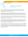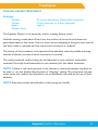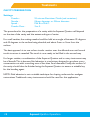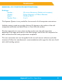
1
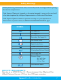
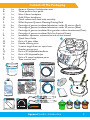
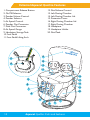
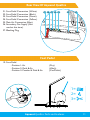
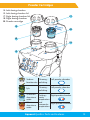
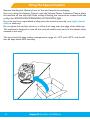
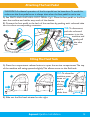
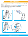
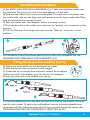
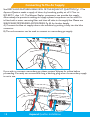
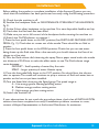
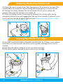
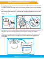
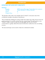
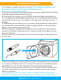
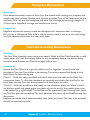
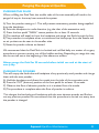
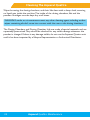
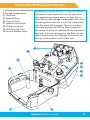
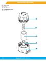
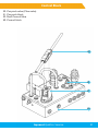
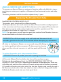
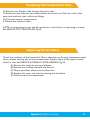
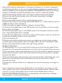
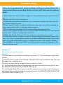
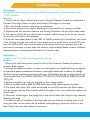
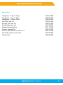
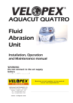
ENGLISH
Fluid Abrasion Unit
AA007000+
Installation, Operation
Maintenance and Service Manual
9051184
0120
WARNING:
Do not connect to the air supply
before reading this manual.
Aquacut Quattro
Technical Manual Iss. 8
I/LIT0020P Issued 18/03/2014
Indications For Use and Contraindications
Indications For Use
The Aquacut Quattro can be used for:
- preparation for pit and fissure sealants.
- removal of composites for restoration.
- cavity preparation.
- cleaning, polishing and stain removal.
- etching of enamel, metal and porcelain.
Contraindications For Use
The Aquacut Quattro is not intended for removal of calculus.
The Aquacut Quattro is not intended for cutting or removal of amalgam.
WARNING: Special consideration must be given to the use of the Aquacut Quattro
on patients who have:
1. Respiratory difficulties
2. Asthma
3. Blocked nasal passages
4. A cold
5. Restricted sodium diet
6. Any other medical problem that may prevent the patient from breathing through
the nose.
Any patient suffering from any of the above conditions should contact their physician
before having treatment with the Aquacut Quattro.
Please refer to INTRODUCTION: SAFETY WARNINGS, Pg 5, and read these safety
notes carefully before attempting to use the machine.
It is strongly recommended that initial training is carried out on glass slides and
extracted teeth before patient treatment with the Aquacut Quattro is attempted.
2
Aquacut Quattro: Introduction
Contents
INTRODUCTION PAGE
INDICATIONS FOR USE AND CONTRAINDICATIONS
2
CONTENTS3
SAFETY WARNINGS5
TABLE OF SYMBOLS7
TECHNICAL DESCRIPTION 8
CONTENTS OF THE PACKAGING9
AQUACUT PARTS AND FEATURES
EXTERNAL AQUACUT QUATTRO FEATURES10
REAR VIEW OF AQUACUT QUATTRO11
FOOT PEDAL11
HANDPIECE12
POWDER CARTRIDGES13
INSTALLATION
SITING THE AQUACUT QUATTRO14
ATTACHING THE FOOT PEDAL15
FILLING THE FLUID TANK15
ASSEMBLING THE HANDPIECE17
FITTING THE DISPOSABLE FEEDLINE AND TIP
17
CONNECTING THE AIR SUPPLY18
INSTALLATION TEST19
REMOVING THE DOSING CHAMBER LIDS
20
INSERTING THE POWDER CARTRIDGES20
PREPARING THE AQUACUT QUATTRO FOR FIRST USE
22
Aquacut Quattro: Introduction
3
Contents
OPERATION
FIRST STEPS TO MASTERING THE AQUACUT QUATTRO
23
SUGGESTED TREATMENT METHODS24
PREPARATIONS BEFORE TREATMENT25
TREATMENTS 26
- Cleaning.
- Fissure Caries.
- Cavity Preparation.
- Removal of Composite Restorations.
- Bonding Orthodontic Brackets.
MAINTENANCE
STERILISING THE HANDPIECE31
HANDPIECE MAINTENANCE32
TWIN TUBE ASSEMBLY MAINTENANCE32
PURGING THE AQUACUT QUATTRO33
CLEANING THE AQUACUT QUATTRO34
SERVICE
INTERNAL VIEW OF THE AQUACUT QUATTRO
35
INTERNAL FILTER ASSEMBLY36
CONTROL BLOCK37
ANNUAL SERVICE CHECKS38
REPLACING THE POWDER PINCH TUBE
38
REPLACING THE AIR FILTERS39
TEST PROCEDURE40
TROUBLESHOOTING41
RECOMMENDED ACCESSORIES44
4
Aquacut Quattro: Introduction
Safety Warnings
ATTENTION- Please read all the following important warnings before
using the Aquacut Quattro:
Only qualified dentists and dental hygienists should use the Aquacut Quattro on
patients.
Before using the Aquacut Quattro:
a) Read the manual thoroughly.
b) Make sure the operator of the unit, any assistants, the patient, and anyone else in the room wear eye protection to BS EN 166 IF 4/5.
c) Make sure the operator of the unit, any assistants, and anyone else in the room, except the patient, wear respiratory masks to BS EN 149 FF2S.
d) Make sure you are in full control of the handpiece, and are aiming the handpiece nozzle in a safe direction.
e) Make sure you have selected the correct powder for the treatment you are performing. Incorrect selection of powder can cause hard tissue damage.
f) Use a high speed intra-oral aspirator during treatment. An extra-oral
aspirator can be used in addition if desired.
e) Ensure machine has adjusted to room temparature (>15°C) before
operating if coming from a cold environment
Patients should consult their physician before having treatment with the Aquacut
Quattro if they have:
a) Respiratory difficulties
b) Asthma
c) Blocked nasal passages
d) A cold
e) A restricted sodium diet
f) Any other medical problem preventing breathing through the nose.
ALWAYS AIM TOWARDS THE INCISAL EDGE OF THE TOOTH.
The Aquacut Quattro may cause soft tissue damage, including inflammation, bleeding,
and creation of an air embolism. The Aquacut Quattro may cause hard tissue damage,
including etching or abrasion of enamel or exposed root surfaces of the teeth.
The disposable feedline and tip should be changed for each patient treatment to
prevent cross-contamination. Ensure that new tips are fitted firmly onto the nozzle.
Used feedlines and tips should be discarded. Attempts to reuse the Aquacut Quattro
feedlines and tips, or to use them with any other micro abrasion machines could be
hazardous.
Aquacut Quattro: Introduction
5
Safety Warnings
In most cases the plastic tip should last long enough for one treatment. However,
during prolonged treatments the tip may need replacing to prevent erratic flow of
fluid.
Do not use the handpiece if the hole in the tip of the nozzle has worn to the outer
edge, or if the swan neck tube has been perforated.
Sterilise the handpiece before first use and between each patient treatment.
The Aquacut Quattro should never be connected to a running water supply as this
will flood the machine. Fluid is supplied to the unit via the fluid tank.
All powders supplied by Velopex are sterile until opened, and the containers are not
reusable.
The powder lines and handpiece should be purged/primed each time you switch between the powder chambers using the powder selector dial (See MAINTENANCE:
PURGING THE AQUACUT, Pg 33).
The Aquacut Quattro produces fine powder dust when in use. Protect sensitive
equipment from this dust.
Only use parts and consumables supplied by Velopex. Non-Velopex products may
damage the unit or alter the performance.
Site the foot pedal carefully so it cannot be operated by accident. Always close the
foot pedal safety cover when not in use. Accidental operation can cause a
uncontrolled and dangerous high pressure stream of abrasive powder.
Do not place the unit in direct sunlight.
When turning the Aquacut Quattro on and off, ensure that the nozzle is aimed into
the inlet of your evacuation unit, and that the evacuation unit is switched on.
When turning the Aquacut Quattro off, wait for the machine to depressurise before
attempting to remove the dosing chamber lids. Depressurising takes roughly
30 seconds.
6
Aquacut Quattro: Introduction
Safety Warnings
When performing maintenance tasks, remove all powder cartridges before opening
the service compartment.
If the Aquacut Quattro is dropped or otherwise damaged, it must not be used until
it has been inspected by a Velopex Representative or Authorised Distributer.
If the Aquacut Quattro ceases to operate correctly, or if you experience a
deterioration in performance, see SERVICE:TROUBLESHOOTING, Pg41.
SYMBOL
OFF
Air Supply Off
Air Supply On
Secondary Gas Supply On
Left Powder Select
Right Powder Select
1
5
+
Powder Flow Volume Control
Cutting Speed Volume Control
Fluid Supply Tank
Pressure Gauge
- A: 2 to 3.5 bar
- B: 4 to 5 bar
- C: 6 to 7 bar
Fluid Volume Control
AIR SUPPLY REQUIREMENTS
Clean dry air to ISO 8573 Class 1.4.1. Pressure between 5 bar (72psi) and 7 bar
(100psi). Maximum flow rate +70 l/min. 4mm O/D input connection
Aquacut Quattro: Introduction
7
Technical Description
READ THIS MANUAL FULLY BEFORE ATTEMPTING TO INSTALL OR
USE THE AQUACUT QUATTRO MACHINE.
The Aquacut Quattro is a fluid abrasion unit which cuts by emitting a stream
of air, fluid and powder from its handpiece. It can be loaded with up to two different
powders for use in cutting and cleaning operations. The only supply the unit requires
is clean, dry air of 5-7 bar which conforms to ISO 8573.1 class 1.4.1. The Velopex
Zephyr Compressor is specifically designed to provide this. See SERVICE:
RECOMMENDED ACCESSORIES, Pg44. The incoming air to the Aqaucut Quattro
is internally regulated to 7 bar. The Aquacut Quattro is operated by pressing the foot
pedal in three modes: Dry, Wash and Cut/Clean. The gas supply, speed, powder chamber, powder volume, and fluid volume can all be adjusted using the five controls available. The handpiece can be removed from the airline for sterilisation.
The overall dimensions of the AQUACUT QUATTRO are:
Width
250mm
Height
240mm
Depth
230mm
Net weight
7.5kgs
The AQUACUT QUATTRO is a class lla medical device.
TYPICAL CUTTING PERFORMANCE THROUGH 1MM OF GLASS.
0.5mm Dia nozzle, 29 micron aluminium oxide.
Speed A, Powder volume 1-2:
10 seconds.
Speed C, Powder volume 4-5:
5 seconds.
0.6mm Dia nozzle, 53 micron aluminium oxide.
Speed A, Powder volume 1-2:
6 seconds.
Speed C, Powder volume 4-5:
2 seconds.
0.8mm Dia nozzle, 53 micron aluminium oxide.
Speed A, Powder volume 1-2:
3 seconds
Speed C, Powder volume 4-5:
1.5 seconds
ENVIRONMENTAL CONDITIONS FOR TRANSPORT AND STORAGE.
The AQUACUT QUATTRO should be kept within the Temperature range -10°C and
+40°C (14°F and 104°F) and below 80% humidity.
8
Aquacut Quattro: Introduction
Contents Of The Packaging
A.
B.
C.
D.
E.
F.
G.
H.
I.
J.
K.
L.
M.
N.
O.
P.
Q.
R.
S.
T.
1 x
1 x
1 x
1x
1 x
1 x
2 x
2 x
1 x
1 x
1 x
1 x
1 x
1 x
1 x
1 x
1 x
1 x
1 x
1 x
Aquacut Quattro fluid abrasion unit.
Three-position foot pedal.
Silver 0.6mm handpiece.
Gold 0.8mm handpiece.
Quick release twin feed tube assembly.
500ml Aquacut Quattro Cleaning/Cutting Fluid.
Cartridge of gamma irradiated aluminium oxide, 53 micron (Red).
Cartridge of gamma irradiated aluminium oxide. 29 micron (Blue).
Cartridge of gamma irradiated fine granular sodium bicarbonate(Clear).
Cartridge of gamma irradiated Sylc for Aquacut(Green)
Installation, operation, maintenance and service manual.
Quick Start Guide
A
Pack of 5 glass slides.
Nozzle cleaning wire.
2 metre length 4mm air input hose.
Powder storage pot.
Pack of 50 disposable feedlines.
Pack of 50 disposable tips.
Pack of 5 spare handpiece parts.
Tube removal tool.
P
E
S
R
O
Q
F
K
B
L
C
T
N
D
Sylc
forfor
Sylc
Aquacut
Aquacut
J
2929
micron
micron
Sodium
5353
micron
Sodium
micron
Oxide
Aluminium
Oxide
Bicarbonate
Aluminium
Oxide
BicarbonateAluminium
Aluminium
Oxide
I
H
G
M
Aquacut Quattro: Introduction
9
External Aquacut Quattro Features
1. Compartment Release Button.
2. On/Off Selector.
3. Powder Volume Control.
4. Powder Selector.
5. Air Speed Control.
6. Powder Out Connector.
7. Fluid Out Connector.
8. Air Speed Gauge.
9. Handpiece Storage Tank.
10. Foot Pedal
11. Foot Pedal Lifting Arch.
12. Fluid Volume Control.
13. Left Dosing Chamber.
14. Left Dosing Chamber Lid.
15. Protective Cover.
16. Right Dosing Chamber Lid.
17. Right Dosing Chamber.
18. Handpiece.
19. Handpiece Holder
20. Fluid Tank.
15
11
14
10
13
12
16
9
17
18
8
19
7
20
6
5
10
4
3
2
1
Aquacut Quattro: Parts and Features
Rear View Of Aquacut Quattro
21. Foot Pedal Connection (White).
22
27 26 25 24 23
21
22. Foot Pedal Connection (Black).
23. Foot Pedal Connection (Green).
24. Foot Pedal Connection (Yellow).
25. Main Air Connection (Blue).
the controls\Utilisation
des commandes\Verwendung der Steu
26. SecondaryUsing
Gas Supply
(Not
Usare
i
comandi\Uso
de
los
controles\Использование
элементов у
used at this time).
27. Blanking Plug
6
B
A
Foot Pedal
1
10. Foot Pedal
2
- Position 1: Air(Dry)
+
- Position 2: Fluid & Air
(Wash)
Using the foot pedal\Utilisation de la pédale à pied\Verwendung de
- Position 3: Powder & Fluid & Air (Cut/Polish)
4
Usare il pedale\Uso del pedal\Использование ножной педали
5
7
3
B
A
11
Aquacut Quattro: Parts and Features
A
F
В
3
P
F
A
П
&
1=
2=
3=
11
Handpiece
29. Twin Tube
30. Handle
32. Hand Grip
33. Feedline and Tip
34. Nozzle
35. Fluid Connection
36. Powder Connection
37. Check Valve
34
32
33
36
35
3
2
-
4
+
1
5
OPEN
30
37
12
29
Aquacut Quattro: Parts and Features
Powder Cartridges
14. Left dosing chamber
15. Left dosing chamber lid
17. Right dosing chamber lid
18. Right dosing chamber
38. Powder cartridge
17
15
38
38
18
14
OFF
3
2
-
4
+
1
5
OPEN
Cleaning –
Sodium
bicarbonate polishing
Left powder chamber
Sylc
Cleaning –
polishing
Left powder chamber
29 micron
aluminium
oxide
Cutting –
Right powder chamber
cavity
preparation
and
Right powder chamber
composite
preparation
53 micron
aluminium
oxide
Aquacut Quattro: Parts and Features
13
Siting The Aquacut Quattro
Remove the Aquacut Quattro from its box and recycle the packaging.
If you are using the Aquacut Quattro with the Velopex Patient Treatment Centre, place
the machine on the top shelf of the trolley, following the instructions received with the
trolley. See SERVICE:RECOMMENDED ACCESSORIES, Pg44.
If you do not have a specialised trolley, place the machine securely on a rigid, sturdy
desk or table top.
Do not place the machine close to, or allow it to hang over, the edge of the table top.
The machine is designed to have all the controls within easy reach of the dentist when
situated in this way.
The unit should be kept within a temperature range of +15ºC and +40ºC, and should
also be kept below 80% humidity.
1
5
-
2
+
4
3
OPEN
14
Aquacut Quattro: Installation
Attaching The Foot Pedal
WARNING: Accidental operation of the foot pedal can be hazardous. To avoid this,
make sure the foot pedal cover is always shut when the foot pedal is not in use.
A) See PARTS AND FEATURES: FOOT PEDAL, Pg11. Place the foot pedal on the floor
near the machine and within easy reach of the dentist.
B) en
Connect
foot àpedal
to the back
the machine by pushing each coloured tube
al\Mise
place de the
la pédale
pied\Anschließen
desof
Fußschalters\
olocación
del
pedal\Подсоедините
ножную
педаль
into its colour-corresponding connector.
TIP: To disconnect,
B
push the coloured
connector in to the machine, and gently pull the tube out.
B
\
C
\
mplissage du réservoir d’eau\Wassertank füllen\
ell’acqua\Llenado del depósito de agua\Заполните резервуар водой
E
Filling The Fluid Tank
B
C
A) Press the compartment release button to open the service compartment. The top
of the machine will swing upwards slightly. This allows access to the fluid tank.
A
F
G
TIP: To close the
machine, press
down on
the top
of the
machine
until it
clicks shut.
click
B) Slide out the fluid tank situated on the right.
X
MA
Aquacut Quattro: Installation
15
Filling The Fluid Tank
C) Peel back the lid and fill with the supplied 500ml Aquacut Quattro Cleaning/Cutting Fluid.
D) Replace the lid.
E) Slide the fluid tank back into the service compartment. NOTE: Ensure that the fluid
tube is correctly inserted through the fluid tank lid as shown below.
F) Close the service compartment.
B
C
E
16
Aquacut Quattro: Installation
Assembling The Handpiece
A) See PARTS AND FEATURES: HANDPIECE, Pg 12. Slide the handpiece handle onto
the twin tube. This goes at the end of the tube without a check valve.
B) Push the twin tubes firmly onto the nozzle tubes. The small twin tube pushes onto
the small nozzle tube, and the large twin tube pushes onto the large nozzle tube. Make
sure the twin tubes are securely in place.
C) Slide the handle onto the handpiece until it is securely in place.
D) Push the free end of the smaller twin tube into the “powder out” connector on the
machine.
E) Push the free end of the larger twin tube into the “fluid out” connector on the
machine.
D
A
E
The handpiece should be sterilised before use and after each subsequent use. See
MAINTENANCE: STERILISING THE HANDPIECE, Pg 31.
Fitting The Disposable Feedline And Tip
A) Take a new tip and fold over the locking tab as shown.
B) Push the tip onto the nozzle until firmly engaged.
C) Rotate the tip so that the free end points toward the handpiece
D) Push one end of the feedline onto the end of the handpiece.
E) Push the other end of the feedline onto the tip.
A
A
B
D
The tips and feedlines are for one time use only, and a new tip and feedline should be
used for each patient. To switch tips and feedlines, remove the existing feedline and
tip and discard. Then follow the steps above. Purge the fluid through the system (See
MAINTENANCE:PURGING THE AQUACUT QUATTRO, Pg 33).
Aquacut Quattro: Installation
17
Connecting To The Air Supply
See PARTS AND FEATURES: REAR VIEW OF THE AQUACUT QUATTRO, Pg 11. The
Aquacut Quattro needs a supply of clean, dry, breathing quality air of 5-7 bar to
ISO 8573.1 class 1.4.1. The Velopex Zephyr compressor can provide this supply.
Alternatively, the practice’s existing air supply system/compressor can be used if it
is fitted with a water removing filter and shut-off valve in the supply line. Please see
SERVICE:RECOMMENDED ACCESSORIES, Pg 44, for further details.
A) Connect the blue air supply tube to the machine by pushing it fully into the blue
connector.
B) The red connector can be used to connect to a secondary gas supply.
If you wish to connect a secondary gas, please contact Velopex for advice before
proceeding. Currently we recommend using a blanking plug when the secondary supply
is not in use.
Alternative gas
Air supply
18
Aquacut Quattro: Installation
Installation Test
Before adding the powder to complete installation of the Aquacut Quattro, you can
check that the installation has been performed correctly using the following procedure:
A) Check that the machine is off.
B) Sterilise the handpiece. Refer to MAINTENANCE: STERILISING THE HANDPIECE,
Pg 31.
C) Fit the 0.6mm silver handpiece to the machine. Fit a new disposable feedline and tip.
E) Check that the fluid tank has been filled.
G) Make sure you are in full control of the handpiece before turning the machine on.
H) Switch the On/Off selector to position I.
I) Press the foot pedal down to the DRY position (See PARTS AND FEATURES: FOOT
PEDAL, Pg 11). Check that air comes out of the nozzle. There should be no fluid or
powder.
J) Press the foot pedal down to the WASH position. Check that you can see water
being drawn up the fluid tube. After a few seconds you should observe the flow of air
change to a fine mist.
K) Turn the Fluid volume dial, observing the spray. Place a paper towel under the nozzle
at a distance of 25-30mm to make the effect easier to see. The Fluid volume range
varies between:
DROPLET - Small quantity of water.Very fine mist.
SPRAY - Larger quantity of water. Heavier spray.
L) Press the foot pedal fully down to the CUT position.You should hear the vibrator
start to operate. The nozzle will continue to spray a mixture of fluid and water, but no
powder as this has not yet been installed.
M) Turn the Speed dial, observing the Speed gauge. The speed range is:
A - Low energy, gentle cleaning/polishing action.
B - Medium energy, medium cutting action.
C - High energy, very fast cutting action.
N) Switch the machine off.
If your observations do not match the procedure above, check that all INSTALLATION
sections have been completed correctly. If installation problems continue to occur,
contact a Velopex Representative or Authorised Distributor for assistance.
Aquacut Quattro: Installation
19
Removing The Dosing Chamber Lids
A) Ensure the unit is turned off and fully depressurised. If the machine has been ON
recently, allow 30 seconds for depressurising before attempting to remove the lids.
B) Unscrew the dosing chamber lids anti-clockwise 2/3 of a turn to relieve the
pressure. Then unscrew a further turn and lift off.
C) Close the dosing chamber by turning lids clockwise. Turn firmly until a strong
resistance is felt from the seal engaging with the top of the chamber. Continue to turn
the lid until you feel the lid tighten against a stop. Always make sure the lids are fully
closed before pressurising the machine.
B
C
Inserting The Powder Cartridges
A) See PARTS AND FEATURES: POWDER CARTRIDGES, Pg 13. Refer to the table at
the bottom to make sure that you fit the correct powder cartridge in the correct
chamber.
B) Peel away the yellow sealing tab on the top of the cartridge.
C) Pull out the yellow draw tab at the bottom of the cartridge.
B
20
C
Aquacut Quattro: Installation
Inserting The Powder Cartridges
D) Line up the rib on the outside of the powder cartridge with the slot on the inside
of the dosing chamber.
E) Slide the powder cartridge down into the dosing chamber until it sits comfortably
inside.
F) If the cartridge sits unevenly or above the top of the dosing chamber, then lift it out
and re-insert. Check that the rib of the powder cartridge slides down the slot in the
dosing chamber.
G) Close the dosing chamber lid.
D
E
F
1
2
1
2
H) To remove a powder cartridge, open the dosing chamber lid and gently lift the
cartridge out of the machine. If the cartridge still contains some powder and will be
used again, place the cartridge carefully into the powder storage pot supplied.
All powder cartridges supplied by Velopex are gamma irradiated. The contents are
sterile until opened. Powder cartridges must not be refilled as the cartridges are
not reusable.
H
Aquacut Quattro: Installation
21
Preparing the Aquacut Quattro For First Use
When training with the Aquacut Quattro, powder could cause mess and damage to
sensitive equipment if the user is not accustomed to operating the machine. For first
use, either work near a sink or lay out a towel on the worksurface. Aim the handpiece
nozzle into the inlet of your evacuation unit. Always wear goggles when operating the
Aquacut Quattro. See INTRODUCTION: SAFETY WARNINGS, Pg 5.
A) Check that all of the INSTALLATION sections have been completed and the
INSTALLATION TEST has been successful.
B) Fit the left dosing chamber with a sodium bicarbonate powder cartridge. Fit the
right dosing chamber with either a 29 or 53 micron aluminium oxide powder cartridge.
C) Switch the powder selection dial to the left dosing chamber.
D) Make sure you are in full control of the handpiece.
E) Switch the On/Off selector to position 1.
F) Press the foot pedal fully down to the CUT position.You should hear the vibrator
start to operate. The nozzle should start to spray a mixture of air, fluid and powder.
N) Turn the Powder volume dial, observing the spray. On a paper towel, you should see
a ring of white powder inside an outer ring of fluid. The powder volume range
varies between:
1 - Low powder content, slow cutting/cleaning
3 - Medium powder content, cutting
5 - High powder content, very fast cutting
O) Turn the Powder selection dial to the right dosing chamber to check that the other
powder flows.
P) The powder needs to be purged whenever you switch between powder chambers
or replace the powder cartridges. The fluid needs to be purged before first use and at
the start of every day. See MAINTENANCE: PURGING THE AQUACUT, Pg 33.
Q)The Aquacut Quattro is now ready for use. Turn off the machine.
The OPERATION section contains training procedures to get started, and
recommended settings for different uses.
If your observations do not match the results above, refer to the SERVICE section
for a full test procedure and troubleshooting tips. Alternatively, refer the problem to a
Velopex Representative or Authorised Distributed.
Use only original Velopex consumable products (powders, handpieces etc.). Other
makes may damage the Aquacut Quattro or negatively alter performance.
22
Aquacut Quattro: Installation
First Steps To Mastering The Aquacut Quatrro
CLEANING TRAINING WITH GLASS SLIDES
The glass microscope slides provided with your machine are similar in hardness to
tooth enamel. Observing the effects of the settings on a glass slide gives a visual display
of the speed of cleaning and polishing. Note: when using polishing powder, no marks
will be made on the glass.
A) Set up a suitable work area - a sink or a towel laid out on the worksurface.
B) Ensure you are in full control of the handpiece and are aiming it in a safe direction.
C) Turn the On/Off Selector to I.
D) Set the powder type to sodium bicarbonate (Left Dosing Chamber).
E) Set the powder volume to 1.
F) Set the speed to A.
G) Switch on the aspirator and hold the glass slide in front of its inlet tube.
H) Aim the handpiece nozzle at the glass slide, 1.5mm from the surface, 30-45º from
perpendicular.
I) Press the foot pedal down to the CUT position.
J) Make light strokes across the slide as if the handpiece were a paintbrush.
K) Observe how the powder rebounds from the surface of the slide. Practice moving
the inlet of the aspirator with the handpiece to efficiently collect any waste powder.
L) Move the foot pedal between polish, wash and dry positions to observe the results.
M) Try using this technique to polish a drinks can. The paint will be removed with no
damage to the metal underneath.
CUTTING TRAINING WITH GLASS SLIDES
These steps show how the Aquacut Quattro cuts through tooth enamel. Observing the
effects on the slide show the size/shape of the various cutting techniques available.
A) Follow steps A to C above.
B) Set the powder type to aluminium oxide (Right Dosing Chamber).
C) Set the powder volume to 3.
D) Set the speed to B.
E) Switch on the aspirator and hold the glass slide in front of its inlet tube.
F) Aim the cutting tip at the glass slide, 1-2mm from the surface, 35-45º from
perpendicular.
G) Try making cuts of 2 seconds duration.Vary the angle and distance of the nozzle
from the glass slide until the required results can be achieved predictably.
H) Try varying the powder volume, powder type, speed, and fluid volume to explore
the full range of cleaning and cutting possibilities.
I) The next step is to use the above techniques to practise cleaning and cutting an
extracted tooth. Experiment with the settings until you are confident you can achieve
predictable, satisfactory results.
Aquacut Quattro: Operation
23
Suggested Treatment Methods
The following treatment suggestions have been prepared with the help of experienced
practising dentists. The methods of treatment are advisory, and each dentist will quickly
develop their own preferences in terms of speed, powder type, powder volume, fluid
volume, and the angle of the cutting nozzle.
TREATMENT TIPS
The end of the cutting nozzle should be held approximately 1.5mm from the working
surface. Avoid holding the nozzle at a right angle to the surface, as this will cause the
powder to rebound and blur the view of the area. Angle the cutting tip towards the
aspirator and instruct the Dental Assistant to follow the nozzle with the aspirator.
The Aquacut Quattro operates with low noise, and has no vibration or heat at the cutting tip. Its ability to cut wet and dry gives it a high flexibility of use.
Local anaesthetic can be offered to nervous patients, however it is generally not
required as fluid abrasion is painless in most cases.
The following treatments use a range of settings. Start at the lower end of the
recommended settings and work up as you build proficiency.
The Aquacut Quattro has three dynamic controls which alter the cutting speed/cleaning rate. These are the speed, the powder volume, and the fluid volume. By increasing
one setting as you decrease another, you can maintain the same cutting speed/cleaning
rate but alter the treatment provided. Use less powder and more speed to improve
viewing of the working area. Use more powder and less speed for sensitive areas.
24
Aquacut Quattro: Operation
Preparations Before Treatment
WARNING: All people in the operating area must wear eye protection to BS EN
166 IF 415
WARNING: All people in the operating area except for the patient must wear
respiratory masks to EN 149 FFP2S
1. It is recommended that a light coating of petroleum jelly is smeared around the
patient’s lips to prevent cracking and to retain some of the outflowing abrasive powder.
2. Rubber dam should be used to protect adjacent teeth and soft tissue.
3. Non-metal Matrix strips should be used to protect adjacent teeth during
interproximal preparations.
4. A bib should be used to protect the patient’s clothes from any out-flow of the
material from the mouth during the course of a treatment.
5. Use a high-speed intra-oral aspirator, preferably with a flared tip.
6. An extra-oral evacuator can also be used with the extraction cone sited below the
patient’s chin.
7. IMPORTANT: To avoid unnecessary damage, when switching from Aluminium
Oxide to Sodium Bicarbonate you must purge the powder.
See MAINTENANCE: PURGING THE AQUACUT, Pg 33.
8. It is recommended that Aquacut Quattro Cleaning/Cutting Fluid should be used in
the Aquacut Quattro Fluid System. The 500ml bottle supplied with the machine should
be discarded when empty. The fluid can be used with all recommended treatments using this instrument.
Please read INTRODUCTION: SAFETY WARNINGS, Pg 5 carefully before using
the Aquacut Quattro.
Aquacut Quattro: Operation
25
Treatments
CLEANING/STAIN REMOVAL
Settings:
Powder -
Nozzle -
Speed -
Powder Flow - Sodium Bicarbonate (clear container).
0.6mm diameter or 0.8mm diameter.
Low A to High B.
1-3
This treatment is particularly easy when using the Aquacut Quattro and gives a
superior finish to the teeth. Where the teeth have been stained by coffee and/or
smoking, fluid abrasion comes into its own.
The fine particles of sodium bicarbonate penetrate the micro crevices of the tooth
surface and the particulate beam easily follows the contours of the tooth surface,
enabling the staining to be removed very quickly and with no discomfort to the patient.
The settings as listed above will create a wide particulate beam of high velocity and
medium particulate density. This is to prevent removal of the tooth enamel but provide
sufficient power to remove staining.
The cutting nozzle should be held approximately 4mm from the surface of the tooth
at an angle of approximately 45 degrees. By moving the nozzle further away from the
surface of the tooth, the rate of removal of staining can be slowed down. Move the
handpiece slowly over the tooth surface.
The most effective way to use fluid abrasion for this procedure is to use the handpiece
of the Aquacut Quattro as if it were a paintbrush, making light strokes across the surface of the tooth until the surface is clean. With experience, the dentist will be able to
work with a high degree of control, the learning curve being similar to that when first
using a high speed drill.
26
Aquacut Quattro: Operation
Treatments
FISSURE CARIES TREATMENT
Settings:
Powder -
Nozzle - Speed - Powder Flow - 29 micron Aluminium Oxide (blue container).
0.5mm diameter or 0.6mm diameter.
High A.
1
The Aquacut Quattro is of particular use for treating fissure caries.
Hold the cutting nozzle about 2mm from the surface of the tooth and direct the
particulate beam at the caries. Use it in short bursts, sweeping it along the vein until all
the dark caries is removed and the sound tooth structure is revealed.
The beauty of the procedure is its speed and the absolute control possible, ensuring
that the minimum amount of tooth structure is removed.
The newly prepared surface, being dry and abraded, is now ready for restorative
materials. Normally local anaesthetic is not necessary for the above treatment.
NOTE: If there is soft caries present in the dentine, a rotary instrument may have to
be used, or use the Sodium Bicarbonate on “cleaning” setting. This is because soft and
moist caries are resilient and therefore not so effectively removed by the use of fluid
abrasion.
NOTE: Stop the process periodically to check progress visually
Aquacut Quattro: Operation
27
Treatments
CAVITY PREPARATION
Settings:
Powder -
Nozzle - Speed - Powder Flow - 53 micron Aluminium Oxide (red container).
0.6mm diameter or 0.8mm diameter.
Mid B to Mid C.
3 to 5.
The procedure for the preparation of a cavity with the Aquacut Quattro will depend
on the size of the cavity and the extent and type of caries.
For small cavities, the cutting nozzle should be held at an angle of between 35 degrees
and 45 degrees to the surface being abraded, and about 2mm or 3mm from the
surface.
The best approach is to use a slow circular motion over the affected area until sound
tooth structure is revealed. The tooth is now ready to be filled in the normal way.
For larger cavities, a combination of the Aquacut Quattro and a rotary instrument may
be of benefit. This is because fluid abrasion is a technique designed to produce a very
conservative cut with a working area of less than 2mm diameter. Finally, the surface of
the cavity should then be finished using the Aquacut Quattro to ensure a suitable key
for the bonding agent.
NOTE: Fluid abrasion is not a suitable technique for shaping undercuts for amalgam
restorations. Traditional rotary instruments should be used for this application.
28
Aquacut Quattro: Operation
Treatments
REMOVAL OF COMPOSITE RESTORATIONS.
Settings:
Powder -
Nozzle - Speed - Powder Flow - 53 micron Aluminium Oxide (red container).
0.6mm diameter or 0.8mm diameter.
Mid B to Mid C.
3 to 5.
The Aquacut Quattro is very useful for the removal of old composite restorations.
Hold the cutting nozzle at an angle of about 45 degrees to the surface of the old
composite restoration and about 2mm or 3mm from the surface.
The best approach is to use a slow circular motion over the old restoration
beginning at the edge, particularly at the failed margin, until all the old composite has
been removed and the cavity preparation completed.
The new restorative can now be applied in the normal manner without any further
treatment. Follow the manufacturer’s recommendations with regard to the use of acid
etch with bonding systems.
Aquacut Quattro: Operation
29
Treatments
BONDING ORTHODONTIC BRACKETS
Settings:
Powder -
Nozzle - Speed - Powder Flow - 29/53 micron Aluminium Oxide (blue/red container).
0.6mm diameter or 0.8mm diameter.
B.
1.
The enamel of the tooth to be treated can be “etched” to the exact size of the
orthodontic bracket at the place of attachment.
This is achieved by holding the cutting nozzle 2mm above the surface of the tooth and
gently moving it in a circular motion over the required area. This will result in a dry
“etched” surface, ready to accept the bonding agent, and the risk of saliva
contamination is greatly reduced because the aluminium oxide dries the surrounding
mucosa.
The same technique can be used to clean the orthodontic brackets.
30
Aquacut Quattro: Operation
Sterilising The Handpiece
The handpiece is supplied clean, but not sterile. The handpiece should be sterilised before first use, and between all subsequent uses.
Do not use an ultra-sonic washer.
A) Remove and discard the disposable feedline and tip (See INSTALLATION: FITTING
THE DISPOSABLE FEEDLINE AND TIP, Pg 17).
B) Disassemble the handpiece parts (See PARTS AND FEATURES: HANDPIECE, Pg
12). For safety, treat used handpiece equipment as if it is contaminated with infectious
material.Wash all of the parts thoroughly in mild soapy water, removing any debris or
blockages.
C) Alternatively, place handpiece parts in automatic washer/disinfector baskets following manufacturer’s recommendations. Wash in a slightly alkaline or neutral pH detergent, as recommended by the manufacturer.
D) When cleaning is completed the handpiece must be sterilised. To steam sterilise/
autoclave the handpiece effectively, the two channels through the handpiece must be
clear and unblocked.
E) Check the flow from the nozzles. If the channels are blocked, use the cleaning wire
to clear them.
F) Place the handpiece in a steam steriliser/autoclave. The handpiece must be sterilised
to a minimum of 134ºC at 2 bar for 3.5 minutes. This will ensure a Sterility Assurance
Level (SAL) of 1 x 10ˉ6. Dry for a minimum of 3 minutes using vacuum drying.
G) A suitable sterilisation pouch should be used to maintain sterility. The plastic parts
should be replaced after 20 cycles. The handpiece should be replaced when cutting
efficiency is impaired.
This cleaning and sterilising procedure satisfies UK Health Technical Memorandum
2030 Washers-Disinfectors and UK Health Technical Memorandum 2010 Sterilisation.
Aquacut Quattro: Maintenance
31
Handpiece Maintenance
Blockages
If the abrasive powder ceases to flow from the nozzle while cutting is in progress, the
nozzle may have become blocked with abrasive particles. Turn off and depressurise the
machine. Now remove the handpiece and clear the blockage by inserting a length of
0.35mm wire (supplied) through the nozzle from the tip.
Inspection
Regularly inspect the cutting nozzle and handpiece for excessive wear or damage.
Do not use a Handpiece if the hole in the tip of the nozzle is worn to the outer edge
or if the abrasive perforates the swan neck tube.
Twin Tube Assembly Maintenance
Cleaning
The Twin Tube Assembly must not be autoclaved. Wash the Twin Tube Assembly in mild
soapy water and rinse thoroughly. Allow to dry completely before use. Always purge
the tubes with Powder and Fluid thoroughly before use.
Inspection
Ensure the Twin Tubes are in good condition and fit together correctly with the
Handpiece. Test the Check Valve is functioning. The valve prevents fluid being forced
back down the tube during use.
Check 1 - With the twin tube filled with fluid, disconnect the tube at the Fluid Out
connection, (item 7). Hold the handpiece up vertically and check that the fluid in the
tube does not drip from the disconnected end. Reconnect the tube.
Check 2 – With the machine in the ‘ready to use’ condition, press the ‘Wash’ control
on the foot pedal and gently press the plastic tip on the end of the nozzle down onto
a flat surface (e.g. a glass slide). The fluid should be prevented from blowing back down
the fluid line past the handpiece. The joint between the plastic tip and feedline may also
disconnect.
Replace the whole check valve assembly if any faults are found. The twin tube assembly
should be replaced annually.
32
Aquacut Quattro: Maintenance
Purging The Aquacut Quattro
PURGING THE FLUID
When re-filling the Fluid Tank, the smaller tube of the twin assembly will need to be
purged of any air that may have entered the system.
A) Turn the powder setting to 1. This will prevent unnecessary powder being expelled
from the handpiece.
B) Point the handpiece in a safe direction (e.g. the inlet of the evacuation unit).
C) Press the foot pedal “WASH” centre position for at least 10 seconds.
D) The machine will expel air from the handpiece and purge the fluid through the line.
E) The procedure is complete when a continuous fine mist sprays from the nozzle and
no air pockets can be seen in the smaller tube.
F) Reset the powder volume as desired.
We recommend that the Fluid Tank is checked and re-filled daily as a matter of surgery
procedure to prevent running out of fluid whilst working. Depending on usage this may
also be carried out at the beginning of the afternoon session.
Always purge the fluid for 20 seconds before initial use and at the start of
every day.
PURGING THE POWDER
This will empty the feed tube and handpiece of any previously used powder and charge
them with the new powder.
A) Hold the handpiece and direct the nozzle into the inlet of the evacuation unit.
B) Press the ‘CUT’ (bottom) position of the foot pedal for at least 10 seconds.
C) Observe the flow of abrasive powder as it is emitted from the nozzle.
D) The procedure is complete when the flow of powder is uniform.
This charges the feed tube and handpiece with the new abrasive powder and flushes
out any previous powder. We recommend that this procedure is carried out every time
the powder is changed.
Aquacut Quattro: Maintenance
33
Cleaning The Aquacut Quattro
Wipe the casing, the dosing chambers, and their lids clean with a damp cloth, ensuring
no liquid gets inside the machine. The inside of the dosing chambers, lids and the
powder cartridges must be kept dry at all times.
WARNING: under no circumstances must any other cleaning agent, including surface
wipes containing alcohol, come into contact with the case or the dosing chambers.
The Dosing Chambers and Dosing Chamber Lids are made of special materials and are
repeatedly pressurised. They should be checked for any visible damage whenever the
powder is changed. If there is any damage visible, do not use the Aquacut Quattro unit
until it has been inspected by a Velopex Representative or Authorised Distributor.
34
Aquacut Quattro: Maintenance
Internal View Of The Aquacut Quattro
1. Compartment release button
9. Storage compartment
21. Fluid tank
39. Internal filters
40. Control block
41. Selector pinch block
42. Outlet connector
43. Fluid Tank Dip Tube
44. Service Release Latch
OPENING THE SERVICE COMPARTMENT:
Full access is only required for service tasks. Push
the compartment release button to open the machine. Remove the storage compartment then reach
into the machine and push the service release latch
right. The latch will disengage. Open the compartment fully, making sure the top section rests on a
flat surface. To close the machine, lift the top section
back over the base, ensuring that the fluid tank dip
tube is inserted into the fluid tank. Press down on
the top of the machine until it clicks shut.
42
39
44
41
43
9
40
39
1
21
Aquacut Quattro: Service
35
Internal Filter Assembly
45. Filter cover.
46. Spring.
47. Filter element.
48. One way valve plug.
49. Filter base.
45
46
47
48
49
36
Aquacut Quattro: Service
Control Block
50. Cut pinch valve (Clear tube)
51. Cut pinch block
52. Fluid Control Valve
40. Control block
50
52
51
40
Aquacut Quattro: Service
37
Service Checks
ANNUAL SERVICE AND SAFETY CHECK.
To ensure your Aqaucut Quatrro continues to function safely and reliably, it is important that you contact your supplier or Velopex and book an annual service and safety
check.
The dosing chambers and lids should be replaced every 2 years.
Replacing The Powder Pinch Tube
See SERVICE: CONTROL BLOCK, Pg 37.
The powder pinch tube should be replaced annually.
The Aquacut Quattro also has 2 internal air filters. These should be visually inspected
at the same time and, if necessary, the filter elements can be replaced. These tubes and
filter elements can be easily replaced without the need for specialist tools. The
procedure should take no longer than 15 minutes.
NOTE: For spare parts you will need to specify the machine Serial Number shown on
the technical label on the back of the machine.
WARNING: Turn off the air supply at the wall outlet and disconnect the air/
secondary gas tubes at the rear of the machine before attempting any maintenance.
All tubes on the Aquacut Quattro are connected using collet fittings as
on the foot pedal and airline connectors. To disconnect the abrasive
tubes, push the coloured connector in, and then gently pull the tube
out.
To replace the powder pinch tube proceed as follows:WARNING: Remove all powder pots before opening the machine
A) Press the Release Catch and allow the front of the machine to open.
B) Undo the Service Release Catch. See SERVICE: INTERNAL VIEW OF THE
AQUACUT QUATTRO, Pg 35. Supporting the machine, lift the upper part of the machine fully over until the cover rests on the work surface and the inside is presented.
C) Locate the Powder pinch valve, which has the clear Powder tube running through it.
D) Disconnect both ends of the clear tube from their collet lock fittings (see above).
E) Slide the Powder pinch tube out of the pinch block.
38
Aquacut Quattro: Service
Replacing The Powder Pinch Tube
F) Slide the new Powder tube through the pinch valve.
G) Route the new tube into the same position as the old one. Push the ends of the
new tube back into their collet lock fittings
H) Close the service compartment.
I) Discard the old pinch tube.
NOTE: It is important to now test the machine to check that it is operating correctly.
See SERVICE: TEST PROCEDURE, Pg 40.
Replacing The Air Filters
Check the condition of the Internal Air Filters whenever performing maintenance tasks
which require opening the service compartment. Replace them if they appear heavily
soiled or wet. See SERVICE: INTERNAL FILTER ASSEMBLY, Pg 36.
A) Remove the cover by turning clockwise.
B) Remove the old filter element and discard.
C) Place a new filter element in the filter base.
D) Replace the cover and close by turning anti-clockwise.
E) Close the service compartment.
Aquacut Quattro: Service
39
Test Procedure
After performing any maintenance on the Aquacut Quattro, or if a fault is suspected,
the following procedure can be used to check that the machine is in working order. If
a fault or problem is found, please see SERVICE: TROUBLESHOOTING, Pg 41. During
testing, it is advisable to point the handpiece into a sink to contain the powder.
A) Fit the left dosing chamber with a cartridge of sodium bicarbonate powder.
B) Ensure the right dosing chamber does not contain any powder cartridges.
C) Wear safety goggles.
D) Turn the powder selection dial to the left dosing chamber.
E) Switch the machine on by turning the On/Off selector to 1. Check that there are no
audible air leaks or loss of pressure.
F) Aim the nozzle at a paper towel, at a distance of about 25mm.
G) Press the foot pedal down to the DRY position. Air should blow out of the nozzle,
but no water or powder.
H) Press the foot pedal down to the WASH position. On the paper towel you should
see a ring of fluid appear, but no powder.
I) Press the foot pedal down to the CUT position. On the paper towel, you should see
a small ring of powder inside an outer ring of fluid.
J) Turn the machine off.
K) Remove the sodium bicarbonate powder cartridge from the left dosing chamber.
L) Fit the right dosing chamber with a cartridge of 29 or 53 micron aluminium oxide.
M) Turn the powder selection dial to the right dosing chamber.
N) Repeat steps E to I.
O) Still pressing CUT, turn the speed dial clockwise and check that the speed of flow
increases. Turn the speed dial anticlockwise and check that the speed of flow decreases.
P) Turn the powder volume dial clockwise and check that the flow of powder becomes
denser. Turn the powder volume dial anticlockwise and check that the flow of powder
becomes less dense.
Q) Turn the fluid volume dial clockwise and check that the flow of fluid becomes more
dense. Turn the fluid volume dial anticlockwise and check that the flow of fluid
becomes less dense.
R) Switch the machine off. Allow it to depressurise and refit the powder cartridges as
required.
If your observations match those detailed above, the machine is operating correctly
and is ready for use. If any of the above steps are not possible because a feature does
not work, or if your observations do not match those detailed above, refer to
SERVICE:TROUBLESHOOTING, Pg 41, or alternatively seek advice from a Velopex
Representative or Authorised Distributor.
40
Aquacut Quattro: Service
Troubleshooting
If you are having problems with your Aquacut Quattro, please follow the
steps below before proceeding further as these will often resolve general
faults.
1. Ensure that the compressed air supply is at the specified pressure, connected and
on.
2. Ensure that the unit is switched on.
3. Check that none of the controls are set to minimum, and that you have selected
the correct dosing chamber.
4. Check that the colour coded foot pedal hoses have been correctly connected to
their matching terminals on the back of the machine.
5. Fill the fluid tank and check the fluid tube is fully submerged in fluid.
6. Ensure the powder chambers are correctly loaded with powder pots, and that the
powder pots contain an ample level of powder.
7. Check the Dosing Chamber Lids are screwed on securely and correctly.
8. Check that there is no water or wet air contaminating the pneumatic system. This
can occur if the compressed air source is not filtered effectively enough. If this is the
case, change the air line filters, clean or replace the air line, and contact a Velopex
Representative or Authorised Dealer who will be able to assess the damage to the
Aquacut Quattro unit.
Symptom:
No air flow through the nozzle.
Action:
1. Ensure that the speed dial is turned up to at least “A”. This should give a detectable
airflow.
2. Check that the nozzle is not blocked. If blocked remove the handpiece and clear the
blockage with a cleaning wire.
3. Ensure the twin tube is straight and has no kinks or folds.
4. If the Internal Filters are not changed they can become soiled, blocking the air line.
See SERVICE: REPLACING THE AIR FILTERS, Pg 39.
5. If the Powder Pinch Tube is worn it will not operate, preventing air from flowing to
the nozzle. This can be resolved by replacing the part. See SERVICE: REPLACING THE
POWDER PINCH TUBE, Pg 38.
Aquacut Quattro: Service
41
Troubleshooting
Symptom:
No powder flow through the nozzle when the foot pedal is pressed down to the
“CUT” position.
Action:
1. Check that you have selected the correct Dosing Chamber, loaded correctly with a
Powder Cartridge. Make sure that the Powder Cartridge is not empty.
2. Turn the Powder Volume control up to maximum.
3. Check that there are no objects blocking the foot pedal from moving normally.
4. Depressurise the machine. Remove the Dosing Chamber Lids and look inside them.
In the centre of each lid you should see a circular rubber bump. If you do not see this
on the lid it will need to be replaced.
5. Press the foot pedal down to the DRY or WASH position.You should hear the noise
of air flowing through the machine. Now press the foot pedal down to the CUT position.You should hear the noise increase as the vibrator starts to operate. If you do
not hear an increase in noise, then the vibrator may be faulty. Please contact a Velopex
Representative or Authorised Distributor for further help.
Symptom:
Irregular flow or no flow of cutting fluid to the tip.
Action:
1. Check that the fluid volume control is not set to minimum. Rotate clockwise to
increase fluid volume.
2. Change the feedline and tip. In most cases the plastic tip should last long enough for
an individual patient treatment. However prolonged treatment or failure to change
feedline and tip between treatments will wear the feedline and tip, causing reduced or
uncontrolled flow. See INSTALLATION: FITTING THE DISPOSABLE FEEDLINE AND
TIP, Pg 23.
3. Ensure the plastic tip is firmly engaged on the cutting nozzle.
4. Check the fluid tank is filled and the fluid tube is fully submerged in the fluid.
5. The check valve (Item 36) could be blocked or stuck. Disconnect the fluid connection and purge the line. This should unblock the valve. If this is not effective, replace the
check valve.
6. Check for a blockage in the supply line. Look at the clear twin tube for any material
blocking the tube.
7. If there are also air bubbles in the fluid tube this can indicate a leaking joint. Look
along the tube to see where the air bubbles are appearing to find the source of the
leak. Check the joint and replace if necessary.
42
Aquacut Quattro: Service
Troubleshooting
Symptom:
Audible air leak and fall in performance
Action:
1. Ensure that the dosing chamber lids are tightly closed. If the dosing chamber lids are
loose or not correctly sealed, a large amount of air will leak from the machine. Turn
the unit off and carefully wipe the inner Lid seal and Dosing Chamber sealing faces.
Screw the lids on tightly until they have reached the end of their thread.
2. Replace pinch tube assembly. See MAINTENANCE: REPLACING THE POWDER
PINCH TUBE, Pg 39.
NOTE: IF THE FAULT CANNOT BE LOCATED AND REPAIRED BY REFERRING
TO THIS TROUBLESHOOTING GUIDE IT WILL BE NECESSARY TO ACQUIRE
THE SERVICES OF A VELOPEX REPRESENTATIVE OR AUTHORISED DEALER
FOR A MORE THOROUGH DIAGNOSIS.
Aquacut Quattro: Service
43
Recommended Accessories
DescriptionPart No
Equipment
Breathing air filter unit I/FIT 8200F
Shut off tapI/FIT 820IF
Pressure regulatorI/FIT 8202F
6mm HoseI/ROL8014F
4mm HoseI/ROL8006F
6mm to 4mm ConverterI/FIT8290F
Replacement Upper Filter Element
I/FIT8355F
Replacement Lower Filter Element
I/FIT8354F
Aquacut StandI/ASS0045F
Consumables
Sodium Bicarbonate Cartridges, Pack of 4 I/PDR 8014F
29 micron Aluminium Oxide Cartridges, Pack of 4 I/PDR 8025F
53 micron Aluminium Oxide Cartridges, Pack of 4
I/PDR 8024F
500ml Fluid BottleI/PAC 8200F
Glass Slides (for cutting practice) I/MIC 0010F
Feedlines and Tips, Pack of 50
I/ASS 8007F
WARNING: All replacement parts and consumables must be sourced from
Velopex to ensure correct and safe functioning of the Aquacut Quatrro.
44
Aquacut Quattro: Service
Recommended Accessories
Spare Parts
Handpiece - 0.4mm Green I/ASS 8189F
Handpiece – 0.6mm Silver I/ASS 8191F
Handpiece – 0.8mm Gold
I/ASS 8192F
Fluid Tank and Lid I/ASS 8194F
Storage Tank and LidI/ASS 8193F
Dosing Chamber Lid
I/ASS 8003F
Nozzle Cleaning Wire I/FIT 8073F
Powder Storage PotI/ASS 8197F
Internal Filter Elements, Pack of 2
I/FIT 8198F
Twin Tube (with check valve)
I/ASS 8020F
Check ValveI/ASS 8004F
Aquacut Quattro: Service
45
Notes
46
Aquacut Quattro: Service
Notes
Aquacut Quattro: Service
47
ENGLISH
Fluid Abrasion Unit
www.velopex.com
9051184
0120
Medivance Instruments Ltd
Barretts Green Road
Harlesden, London
NW10 7AP
Tel: +44 (0) 20 8965 2913
Fax: +44 (0) 20 8963 1270
Velopex is a trademark of
Medivance Instruments Ltd.
OFFICE: FRANCE
Velopex International
14 route de Montreuil le Gast
B.P.45
35520 Melesse
Tel: +33 (0) 2.99.13.22.59
Fax: +33 (0) 2.99.13.22.60
OFFICE: USA
Velopex International
105 East 17th Street
Saint Cloud
Florida 34769
Tel: +1 (407) 957 3900
Fax: +1 (407) 957 3927