1
Application Note
EEPROM Emulation
32 Library
EEL - T06
EEPROM Emulation Library for
RC03F Flash based V850 devices
All information contained in these materials, including products and product specifications,
represents information on the product at the time of publication and is subject to change by
Renesas Electronics Corp. without notice. Please review the latest information published by
Renesas Electronics Corp. through various means, including the Renesas Technology Corp.
website (http://www.renesas.com).
www.renesas.com
R01AN1035ED0100, Rev. 1.0
Mar 21, 2012
Notice
1. All information included in this document is current as of the date this document is issued. Such
information, however, is subject to change without any prior notice. Before purchasing or using
any Renesas Electronics products listed herein, please confirm the latest product information with
a Renesas Electronics sales office. Also, please pay regular and careful attention to additional
and different information to be disclosed by Renesas Electronics such as that disclosed through
our website.
2. Renesas Electronics does not assume any liability for infringement of patents, copyrights, or other
intellectual property rights of third parties by or arising from the use of Renesas Electronics
products or technical information described in this document. No license, express, implied or
otherwise, is granted hereby under any patents, copyrights or other intellectual property rights of
Renesas Electronics or others.
3. You should not alter, modify, copy, or otherwise misappropriate any Renesas Electronics product,
whether in whole or in part.
4. Descriptions of circuits, software and other related information in this document are provided only
to illustrate the operation of semiconductor products and application examples. You are fully
responsible for the incorporation of these circuits, software, and information in the design of your
equipment. Renesas Electronics assumes no responsibility for any losses incurred by you or
third parties arising from the use of these circuits, software, or information.
5. When exporting the products or technology described in this document, you should comply with
the applicable export control laws and regulations and follow the procedures required by such
laws and regulations. You should not use Renesas Electronics products or the technology
described in this document for any purpose relating to military applications or use by the military,
including but not limited to the development of weapons of mass destruction. Renesas
Electronics products and technology may not be used for or incorporated into any products or
systems whose manufacture, use, or sale is prohibited under any applicable domestic or foreign
laws or regulations.
6. Renesas Electronics has used reasonable care in preparing the information included in this
document, but Renesas Electronics does not warrant that such information is error free. Renesas
Electronics assumes no liability whatsoever for any damages incurred by you resulting from
errors in or omissions from the information included herein.
7. Renesas Electronics products are classified according to the following three quality grades:
“Standard”, “High Quality”, and “Specific”. The recommended applications for each Renesas
Electronics product depends on the product’s quality grade, as indicated below. You must check
the quality grade of each Renesas Electronics product before using it in a particular application.
You may not use any Renesas Electronics product for any application categorized as “Specific”
without the prior written consent of Renesas Electronics. Further, you may not use any Renesas
Electronics product for any application for which it is not intended without the prior written consent
of Renesas Electronics. Renesas Electronics shall not be in any way liable for any damages or
losses incurred by you or third parties arising from the use of any Renesas Electronics product for
an application categorized as “Specific” or for which the product is not intended where you have
failed to obtain the prior written consent of Renesas Electronics.
8. The quality grade of each Renesas Electronics product is “Standard” unless otherwise expressly
specified in a Renesas Electronics data sheets or data books, etc.
“Standard”:
Computers; office equipment; communications equipment; test and measurement
equipment; audio and visual equipment; home electronic appliances; machine
tools; personal electronic equipment; and industrial robots.
“High Quality”: Transportation equipment (automobiles, trains, ships, etc.); traffic control
systems; anti-disaster systems; anti- crime systems; safety equipment; and
medical equipment not specifically designed for life support.
“Specific”:
Aircraft; aerospace equipment; submersible repeaters; nuclear reactor control
systems;medical equipment or systems for life support (e.g. artificial life support
devices or systems), surgical implantations, or healthcare intervention (e.g.
excision, etc.), and any other applications or purposes that pose a direct threat to
human life.
9. You should use the Renesas Electronics products described in this document within the range
specified by Renesas Electronics, especially with respect to the maximum rating, operating
supply voltage range, movement power voltage range, heat radiation characteristics, installation
and other product characteristics. Renesas Electronics shall have no liability for malfunctions or
damages arising out of the use of Renesas Electronics products beyond such specified ranges.
10. Although Renesas Electronics endeavors to improve the quality and reliability of its products,
semiconductor products have specific characteristics such as the occurrence of failure at a
certain rate and malfunctions under certain use conditions. Further, Renesas Electronics products
are not subject to radiation resistance design. Please be sure to implement safety measures to
guard them against the possibility of physical injury, and injury or damage caused by fire in the
event of the failure of a Renesas Electronics product, such as safety design for hardware and
software including but not limited to redundancy, fire control and malfunction prevention,
appropriate treatment for aging degradation or any other appropriate measures. Because the
evaluation of microcomputer software alone is very difficult, please evaluate the safety of the final
products or system manufactured by you.
11. Please contact a Renesas Electronics sales office for details as to environmental matters such as
the environmental compatibility of each Renesas Electronics product. Please use Renesas
Electronics products in compliance with all applicable laws and regulations that regulate the
inclusion or use of controlled substances, including without limitation, the EU RoHS Directive.
Renesas Electronics assumes no liability for damages or losses occurring as a result of your
noncompliance with applicable laws and regulations.
12. This document may not be reproduced or duplicated, in any form, in whole or in part, without prior
written consent of Renesas Electronics.
13. Please contact a Renesas Electronics sales office if you have any questions regarding the
information contained in this document or Renesas Electronics products, or if you have any other
inquiries.
(Note 1) “Renesas Electronics” as used in this document means Renesas Electronics
Corporation and also includes its majority- owned subsidiaries.
(Note 2) “Renesas Electronics product(s)” means any product developed or manufactured
by or for Renesas Electronics.
Regional Information
Some information contained in this document may vary from country to country. Before using any
Renesas Electronics product in your application, please contact the Renesas Electronics office in your
country to obtain a list of authorized representatives and distributors. They will verify:
•
• Device availability
•
• Ordering information
•
• Product release schedule
•
• Availability of related technical literature
•
• Development environment specifications (for example, specifications for
third-party tools and components, host computers, power plugs, AC supply
voltages, and so forth)
•
• Network requirements
In addition, trademarks, registered trademarks, export restrictions, and other legal issues may also vary
from country to country.
Visit
http://www.renesas.com
to get in contact with your regional representatives and distributors.
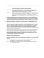
Preface
Readers This manual is intended for users who want to understand the functions of the
concerned libraries.
Purpose This manual presents the software manual for the concerned libraries.
Organisation This document describes the following sections:
•
Architecture
•
Implementation and Usage
•
API
Note Additional remark or tip
Caution Item deserving extra attention
Numeric notation Binary:
xxxx or xxxB
Decimal:
xxxx
Hexadecimal
xxxxH or 0x xxxx
Numeric prefixes representing powers of 2 (address space, memory capacity):
K (kilo):
210 = 1024
M (mega):
220 = 1024² = 1,048,576
G (giga):
230 = 1024³ = 1,073,741,824
Register contents X, x = don’t care
Diagrams Block diagrams do not necessarily show the exact software flow but the
functional structure. Timing diagrams are for functional explanation purposes only,
without any relevance to the real hardware implementation.
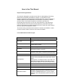
How to Use This Manual
Purpose and Target Readers
This manual is designed to provide the user with an understanding of the library
itself and the functionality provided by the library. It is intended for users
designing applications using libraries provided by Renesas. A basic knowledge of
software systems as well as Renesas microcontrollers is necessary in order to
use this manual. The manual comprises an overview of the library, its
functionality and its structure, how to use it and restrictions in using the library.
Particular attention should be paid to the precautionary notes when using the
manual. These notes occur within the body of the text, at the end of each section,
and in the Special Considerations section.
The revision history summarizes the locations of revisions and additions. It does
not list all revisions. Refer to the text of the manual for details.
List of Abbreviations and Acronyms
Abbreviation
API
Full Form
Application Programming Interface
Flash Area
Area of Flash consists of several coherent Flash
Blocks
Code Flash
Embedded Flash where the application code or
constant data is stored.
CR
Complementary Read
Data Flash
Embedded Flash where mainly the data of the
EEPROM emulation are stored.
Data Set
Instance of data written to the Flash by the EEPROM
Emulation Library (EEL), identified by the Data Set ID
DS
Short for Data Set
Dual Operation
Dual operation is the capability to access flash
memory during reprogramming another flash memory
range.
Dual operation is available between Code Flash and
Data Flash. Between different Code Flash macros
dual operation depends on the device implementation.
ECC
Error Correction Code
EEL
EEPROM Emulation Library
EEPROM
Electrically erasable programmable read-only memory
EEPROM emulation
In distinction to a real EEPROM the EEPROM
emulation uses some portion of the flash memory to
emulate the EEPROM behaviour. To gain a similar
behaviour some side parameters have to be taken in
account.
FAL
Flash Access Library (Flash access layer)
FDL
Data Flash Library (Data Flash access layer)
Flash
Electrically erasable and programmable nonvolatile
memory. The difference to ROM is, that this type of
memory can be re-programmed several times.
Flash Block
A flash block is the smallest erasable unit of the flash
memory.
Flash Macro
A certain number of Flash blocks is grouped together
in a Flash macro.
HWd
Half Word (16bit) data
HWIdx
Half Word Index (index to HWd data)
ID
Identifier of a Data Set instance in the Renesas
EEPROM Emulation
NVM
Non volatile memory. All memories that hold the
value, even when the power is cut off. E.g. Flash
memory, EEPROM, MRAM...
RAM
“Random access memory” - volatile memory with
random access
REE
Renesas Electronics Europe GmbH
REL
Renesas Electronics Japan
ROM
“Read only memory” - nonvolatile memory. The
content of that memory can not be changed.
Segment / Section
Segment of Flash is a part of the flash that might
consist of several blocks. Important is, that this
segment can be protected against manipulation.
Serial programming
The onboard programming mode is used to program
the device with an external programmer tool.
Virtual Flash blocks
The EEL merges together small physical Flash blocks
to bigger virtual Flash blocks which are then managed
in the ring buffer
All trademarks and registered trademarks are the property of their respective
owners.
Table of Contents
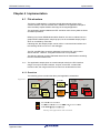
Chapter 1
Introduction ........................................................................ 10
Chapter 2
Architecture ........................................................................ 11
2.1
Flash Infrastructure.......................................................................................11
2.1.1
2.1.2
2.1.3
2.2
2.3
2.4
2.5
2.6
Layered software architecture......................................................................12
Data Flash Pools............................................................................................13
Safety Considerations...................................................................................14
Feature Overview...........................................................................................14
EEL Flash management ................................................................................15
2.6.1
2.6.2
2.6.3
2.6.4
2.6.5
2.7
Chapter 3
Chapter 4
ID-L and IDX tables..........................................................................................................29
Library startup phase......................................................................................................33
Normal operation phase .................................................................................................35
Implementation ................................................................... 37
File structure..................................................................................................37
4.1.1
4.1.2
4.2
4.3
EEL Design ......................................................................... 27
Start-up processing.......................................................................................31
Function & command execution times & latencies ....................................33
3.8.1
3.8.2
4.1
Basic Concept..................................................................................................................23
DP and RP ........................................................................................................................23
Block overlapping DS’s ..................................................................................................24
Storage structure details ................................................................................................25
Asynchronous architecture ..........................................................................27
Flash interrupt support .................................................................................27
EEL user operations priority ........................................................................27
Background operations ................................................................................28
Error and warning levels...............................................................................29
Data Set search and read..............................................................................29
3.6.1
3.7
3.8
Physical vs. virtual address range ................................................................................15
Physical vs. virtual Flash blocks ...................................................................................15
Virtual block structure ....................................................................................................15
Block lifecycle..................................................................................................................17
Internal block structure...................................................................................................18
EEL Data Sets Management .........................................................................23
2.7.1
2.7.2
2.7.3
2.7.4
3.1
3.2
3.3
3.4
3.5
3.6
Complementary Read Flash ...........................................................................................11
Dual operation..................................................................................................................11
Flash granularity..............................................................................................................12
Overview...........................................................................................................................37
Delivery package directory structure and files ............................................................38
EEL Linker sections ......................................................................................40
MISRA Compliance........................................................................................41
Chapter 5
5.1
5.2
Pre-compile configuration ............................................................................42
Run-time configuration .................................................................................42
5.2.1
5.2.2
5.3
Chapter 6
EEL Implementation into the user application ................ 73
Application sample..........................................................................................................73
Standard EEL life cycle.................................................................................73
6.2.1
6.2.2
6.2.3
6.3
Initialization / Shut down ................................................................................................54
Suspend / Resume ..........................................................................................................59
Operational functions .....................................................................................................61
Administrative functions ................................................................................................68
First steps ......................................................................................................73
6.1.1
6.2
Error Codes ......................................................................................................................48
User operation request structure ..................................................................................49
Driver status.....................................................................................................................51
EEL Functions ...............................................................................................54
5.4.1
5.4.2
5.4.3
5.4.4
6.1
FDL run-time configuration elements ...........................................................................42
EEL run time configuration elements............................................................................44
Data Types .....................................................................................................48
5.3.1
5.3.2
5.3.3
5.4
User Interface (API) ............................................................ 42
Device start-up.................................................................................................................74
Device normal operation.................................................................................................77
Device power down .........................................................................................................78
Special considerations .................................................................................79
6.3.1
6.3.2
6.3.3
6.3.4
6.3.5
6.3.6
6.3.7
6.3.8
Endurance calculations ..................................................................................................79
Data Flash initialization...................................................................................................79
Library handling by the user application ......................................................................81
Concurrent Data Flash accesses ...................................................................................82
Entering power safe mode..............................................................................................83
Library behaviour after operation interruption.............................................................83
Application update issues ..............................................................................................84
Device performance during active Flash operations...................................................88
EEPROM Emulation Library
Introduction
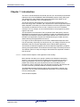
Chapter 1 Introduction
This user’s manual describes the internal structure, the functionality and software
interfaces (API) of the RENESAS V850 EEPROM Emulation Library (EEL) type
T06, designed for V850 based Flash devices with Data Flash based on the
RC03F Flash technology, such as V850E2S/Fx4-L.
The device features differ depending on the used Flash implementation and
basic technology node. Therefore, pre-compile and run-time configuration options
allow adaptation of the library to the device features and to the application needs.
The libraries are delivered in source code. However it has to be considered
carefully to do any changes, as not intended behaviour and programming faults
might be the result.
The development environments of the companies Green Hills (GHS), IAR and
RENESAS are supported. Due to the different compiler and assembler features,
especially the assembler implementations differ between the environments. So,
the library and application programs are distributed using an installer tool that
allows selecting the appropriate environment.
For support of other development environments, additional development effort
may be necessary. Especially, but maybe not only, the calling conventions to the
assembler code and compiler dependent section defines differ significantly.
The libraries are delivered together with device dependent application programs,
showing the implementation of the libraries and the usage of the library functions.
The different options of setup and usage of the libraries are explained in detail in
this document.
Caution Please read all chapters of the application note carefully.
Much attention has been put to proper conditions and limitations description.
Anyhow, it can never be ensured completely that all not allowed concepts of
library implementation into the user application are explicitly forbidden. So,
please follow exactly the given sequences and recommendations in this
document in order to make full use of the libraries functionality and features and
in order to avoid any possible problems caused by libraries misuse.
The EEPROM emulation libraries together with the application samples, this
application note and other device dependent information can be downloaded
from the following URL:
www.renesas.eu/update
R01AN1035ED0100 Rev. 1.0
Application Note
10
EEPROM Emulation Library
Architecture
Chapter 2 Architecture
2.1 Flash Infrastructure
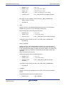
2.1.1 Complementary Read Flash
Based on the different application needs, the Flash implementation used for Data
Flash differs from the Code Flash implementation. In order to achieve the
required high endurance (erase cycles), Renesas decided for a Complementary
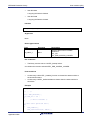
Read (CR) Flash implementation on Data Flash. Each data bit is realized by two
Flash cells, which are programmed to the opposite direction data bit. The cell
value difference is read to judge the data value:
Data bit
Flash cell 1level
Flash cell 2 level
0
1
high
low
low
high
Resulting from the implementation, erased Flash (both Flash cells with
same/similar level) has a very small differential level. The resulting data bit
judgement has an undefined result, but with a tendency to formerly written data.
This need to be considered on interpretation of the read values:
•
The lower level library FDL provides a blank check to distinguish between
erased and written Flash on read level (not exact electrical margins, please
refer to the FDL UM).
•
The EEL handles this CR behaviour of erased cells in the library concept.
•
When inspecting the Data Flash contents (e.g. using a debugger), the
debugger need to provide the information on the Flash status (erased/written)
2.1.2 Dual operation
Common for all Flash implementations is, that during Flash modification
operations (Erase/Write) a certain amount of Flash memory is not accessible for
any read operation (e.g. program execution or data read).
This does not only concern the modified Flash range, but a certain part of the
complete Flash system. The amount of not accessible Flash depends on the
device architecture.
A standard architectural approach is the separation of the Flash into Code Flash
and Data Flash. By that, it is possible to read from the Code Flash (to execute
program code or read data) while Data Flash is modified, and vice versa. This
allows implementation of EEPROM emulation concepts with Data storage on
Data Flash while all program code is executed from Code Flash.
If not mentioned otherwise in the device users manuals, the devices with Data
Flash are designed according to this standard approach.
Note It is not possible to modify Code Flash and Data Flash in parallel!
R01AN1035ED0100 Rev. 1.0
Application Note
11
EEPROM Emulation Library
Architecture
2.1.3 Flash granularity
The Data Flash can be erased in 32 Byte units.
The Data Flash can be written and read in 2 Byte units. As the CPU is able to
handle 4 Byte units as one “Word”, this document often refers to the “Half Word”
(HWd) as 2 Byte units.
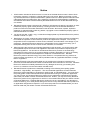
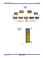
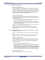
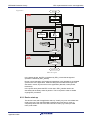
2.2 Layered software architecture
This chapter describes the function of all blocks belonging to the EEPROM
Emulation System.
Even though this specification describes the functional block EEL, a short
description of all concerned functional blocks and their relationship can be
beneficial for the general understanding.
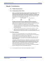
Figure 2-1
Rough symbolic relationship between the functional blocks
Application
The functional block “Application” should not use the functions offered by the FDL
directly. FDL functions are reserved for EEL only. Exception is when the user
implements a proprietary EEPROM emulation, it has to use functions provided by
the FDL only.
R01AN1035ED0100 Rev. 1.0
Application Note
12
EEPROM Emulation Library
Architecture
EEPROM Emulation Library (EEL)
The functional block “EEPROM Emulation library” is the subject of this document.
It offers all functions and commands the “Application” can use in order to handle
its EEPROM data.
Data Flash Access Library (FDL)
The “Data Flash Access Library” offers an interface to access any user-defined
flash area, so called “FDL-pool” (described in next chapter). Beside the
initialization function the FDL allows the execution of access-commands like write
as well as a suspend-able erase command.
Note General requirement is to be able to deliver pre-compiled EEL libraries, which
can be linked to either Data Flash Access Libraries (FDL) or Code Flash Access
Libraries (FCL). To support this, a unique API towards the EEL must be provided
by these libraries. Following that, the standard API prefix FDL_... which would
usually be provided by the FDL library, will be replaced by a standard Flash
Access Layer prefix FAL_...
All functions, type definitions, enumerations etc. will be prefixed by FAL_ or fal_.
Independent from the API, the module names will be prefixed with FLD_ in order
to distinguish the source/object modules for Code and Data Flash.
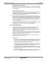
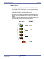
2.3 Data Flash Pools
The FDL pool defines the Flash blocks, which may be accessed by any FDL
operation (e.g. write, erase). The limits of the FDL pool are taken into
consideration by any of the FDL flash access commands. The user can define
the size of the FDL-pool freely at project compilation time, while usually the
complete Data Flash is selected.
The FDL pool provides the space for the EEL pool which is allocated by the EEL
inside the FDL-pool. The EEL pool provides the Flash space for the EEL to store
the emulation data and management information.
All FDL pool space not allocated by the EEL pool is freely usable by the user
application, so is called the “User pool”.
Pools details:
•
FDL-pool is just a place holder for the EEL-pool. It does not allocate any flash
memory. The FDL-pool descriptor defines the valid address space for FDL
access to protect all flash outside the FDL-pool against destructive access
(write/erase) by a simple address check in the library.
To simplify function parameter passing between FDL and the higher layer the
physical Flash addresses (e.g. 0xfe000000….0xfe00FFFF) are transformed
into a linear address room 0x0000….0xFFFF used by the FDL.
•
EEL-pool allocates and formats (virgin initialization) all flash blocks belonging
to the EEL-pool. The header data are generated in proper way to be directly
usable by the application.
•
User Pool is completely in the hands of the user application. It can be used to
build up an own user EEPROM emulation or to simply store constants.
R01AN1035ED0100 Rev. 1.0
Application Note
13
EEPROM Emulation Library
Architecture
Figure 2-2
Data Flash / FDL Pool
2.4 Safety Considerations
EEPROM emulation in the automotive market is not only operated under normal
conditions, where stable function execution can be guaranteed. In fact, several
failure scenarios should be considered.
Most important issue to be considered is the interruption of a function e.g. by
power fail or Reset.
Differing from a normal digital system, where the operation is re-started from a
defined entry point (e.g. Reset vector), the EEPROM emulation modifies Flash
cells, which is an analogue process with permanent impact on the cells. Such an
interruption may lead to instable electrical cell conditions of affected cells. This
might be visible by undefined read values (read value != write value), but also to
defined read values (blank or read value = write value). In each case the read
margin of these cells is not given. The value may change by time into any
direction.
This is considered in the emulation design. Safety relevant considerations and
concepts are mentioned in dedicated sup-chapters in this document.
2.5 Feature Overview
The new EEL concept improves quite some features known from today’s V850
MF2/UX4 EEELib. Beside the same kind of user data management, based on
data sets (DS) identified with certain IDs, many new or extended features are
implemented:
The old V850 MF2/UX4 EEELib searches DSs in the Flash memory on every
Read access as well as during the Refresh process. Even though being executed
in background, the read latency is very big.
In order to overcome this situation, the new EEL concept uses a RAM table to
store the latest DS instance. So, the read access performance will be significantly
increased.
The startup worst case performance is significantly improved regarding the V850
MF2/UX4 implementation as the DS management does no longer need to
overwrite data and refresh complete sections in order to ensure the data
consistency.
Ring buffer style Flash block management reaches better Flash endurance
usage. While the old concept required a constant “copy zone” in order to execute
R01AN1035ED0100 Rev. 1.0
Application Note
14
EEPROM Emulation Library
Architecture
Refresh section operations, the new concept requires copy space only if the data
at the ring buffer tail (eldest part of the ring buffer) is not already written new in
the ring buffer.
2.6 EEL Flash management
2.6.1 Physical vs. virtual address range
To simplify function parameter passing between the FAL and the EEL the
physical space used to directly access the device is transformed into a linear
address room starting from 0x00000000 (FDL address range). This should save
space in the reference-area of the EEPROM driver when writing new instance
references. Also the protection mechanisms can be implemented in a more
effective way.
2.6.2 Physical vs. virtual Flash blocks
The EEL concept relies on Flash blocks of a reasonable size to store block
management data and Data Sets (DSs). As the concept is derived from the EEL
T05 used for UX6LF Flash based devices with 2kB Flash block size, also the T06
library merges the physical RC03F Flash blocks together to virtual Flash blocks
of 2kB which are managed by the EEL.
The transition from physical to virtual blocks is done within the EEL near to the
FDL interface. As the FDL API handles physical blocks, an EEL internal low level
routine converts the virtual blocks to physical blocks before calling the FDL to
execute Flash erase. The complete EEL works on virtual blocks.
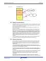
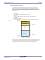
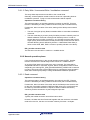
2.6.3 Virtual block structure
The virtual Flash blocks are used as a kind of ring buffer. The below picture
considers a write pointer staying fix, while the ring buffer rotates clockwise.
Every block reaching the write pointer gets activated. This block is called the
active zone head.
When a block reaches the end of the active zone it is called the active zone tail.
Before getting activated again the block is prepared.
Each virtual block will pass a complete life cycle on every ring buffer loop.
R01AN1035ED0100 Rev. 1.0
Application Note
15
EEPROM Emulation Library
Architecture
Figure 2-3
,
Basic ring buffer structure
R01AN1035ED0100 Rev. 1.0
Application Note
16
EEPROM Emulation Library
Architecture
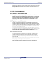
2.6.4 Block lifecycle
The life cycle of a block passes different steps which are largely marked inside
the block header in specific half words.
The active state and the occupied state are not explicitly distinguished by block
header information. They all have the active marker set. Anyhow, inside the
library only the latest block containing required data (not full, the write pointer
points into this block) contains the active status. All other blocks containing
required data are full and so, are treated internally occupied.
The consumed blocks, blocks under erasing or other blocks with undefined state
due to power fail are considered as invalid and are all treated in the same way by
the library. They enter the preparation phase in the next life cycle and are then
prepared.
In case of an erase fail the affected Flash block is considered to be defect and is
so marked excluded. This block will not enter the lifecycle again.
Figure 2-4
Block Lifecycle
R01AN1035ED0100 Rev. 1.0
Application Note
17
EEPROM Emulation Library
Architecture
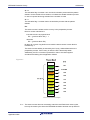
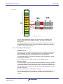
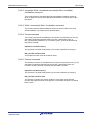
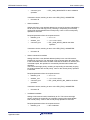
2.6.5 Internal block structure
Every Flash block of the logical ring buffer contains 3 areas. While the block
header size is fix, the data zone and the Reference (REF) zone grow towards
each other. A block is full and the next block must be activated, when only 1~3
blank half words (depending on different conditions) as delimiter remain between
the two zones.
•
Block header:
The header contains the block status information.
•
Data Zone:
Contains the pure user data to be stored without any management
information.
•
Reference (REF) zone:
This is a table with entries containing the references (pointers) to the data.
Figure 2-5
Block bottom
address
Block Header
REF Zone
Growing
Blank
Data Zone
Growing
Block top
address
Basic Block structure
While the block management (including the block header) is described in the next
sub-chapters, the data management within the blocks (including REF Zone and
Data Zone) is described in the main chapter EEL Data Sets Management.
R01AN1035ED0100 Rev. 1.0
Application Note
18
EEPROM Emulation Library
Architecture
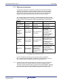
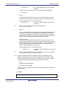
2.6.5.1 Block Header
The block header contains the block status half words.
HW-idx
0
1
2
3
4
5
6
Figure 2-6
byte 0
byte 1
I0
E0
P
A0
A1
EC
invalid flag 0
exclude flag 0
prepare flag
active flag 0
active flag 1
reserved
32bit erase counter (8bit CS protected)
CS
8
RWP
32bit reference write pointer (8 bit CS protected)
CS
10
RDP
Pool full read data pointer (8 bit CS protected)
CS
12
16
17
reserved
I1
E1
invalid flag 1
exclude flag 1
Block header half words
I – 0, I – 1:
The flags are written by the Refresh process when a block does not contain any
more valid DSs with relevant data and shall be marked for the later Prepare
process.
Furthermore, the invalidation flags are written during execution of the startup
process, when a block status is detected as invalid but the flags are not valid.
This ought to result from an interrupted invalidation of the virtual block.
•
By writing 0x5555, the block is marked invalid
•
If on startup the half words are not blank and not matching one of the above
patterns, the block is judged invalid. This is the block default state which may
result from a power fail during block status change operations
•
If on startup the entries are blank, the other header entries determine the
block status
E – 0, E – 1:
The flags are written to 0x5555 to mark a virtual block excluded. This is done,
when the Flash erase returns an erase error. The blocks are then judged defect.
P:
The prepare marker is set by the preparation process. With the pattern 0x5555,
the block is marked prepared.
R01AN1035ED0100 Rev. 1.0
Application Note
19
EEPROM Emulation Library
Architecture
A – 0:
The activation flag 0 is written 1st in the block activation process with the pattern
0x5555. It locks the block for activation, to indicate the started activation process.
In case of a power fail during activation the next block is used.
A – 1:
The activation flag 1 is written last in the activation process with the pattern
0x5555.
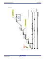
EC:
The erase counter is written as the 1st entry in the preparation process.
Rule for counter calculation is:
if the block is the 1st physical block
EC = ( previous block EC ) + 1
otherwise
EC = ( previous block EC )
By that rule, on each ring buffer turn around the erase counter in each block is
increased by 1.
The erase counter stability is ensured by the P entry, written afterwards in the
preparation process. If the P entry is valid, the EC is electrically stable.
Additionally, the EC is checksum protected in order to be robust against
accidental overwriting due to application failures.
Figure 2-7
Erase Counter example
Note The erase counter does not necessarily match the real Flash block erase cycles,
but only the erase cycles since the EEPROM emulation has been set up last time.
R01AN1035ED0100 Rev. 1.0
Application Note
20
EEPROM Emulation Library
Architecture
The erase counter is affected by Data Flash complete erase or manual Flash
modification (programmer or debugger).
RWP:
The reference write pointer is written in the activation process after A – 0 and
before A – 1. It points to the previous block separator between REF zone and
Data zone. By that, the EEL knows for each occupied block the last REF zone
entry. The RWP stability is ensured by the A - 1 entry, written afterwards in the
activation process. If the A - 1 entry is valid, the RWP is electrically stable.
Additionally, the RWP is checksum protected in order to be robust against
accidental overwriting due to application failures
Figure 2-8
Reference Write Pointer
RDP:
The Read Data Pointer is used for special treatment of the situation, that only
one block is left for refresh.
The RDP is not related to the block status and so, need not be considered in the
power fail FMEA considerations regarding block status management.
Reserved areas:
Reserved header areas are unused. These areas result from the fact that I1 and
E1 have to be placed into another physical Flash block.
R01AN1035ED0100 Rev. 1.0
Application Note
21
EEPROM Emulation Library
Architecture
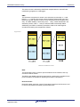
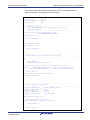
2.6.5.2 Block header data transitions
During EEPROM emulation block header information changes according to the
block status. The following table shows the data change process and the
resulting block header data.
As the RDP word (see last sub-chapter) is not block status related, it is not
mentioned here.
Figure 2-9
Block Operation
Status
-
erased
ongoing
ongoing
ongoing
finished
ongoing
ongoing
ongoing
ongoing
ongoing
finished
ongoing
ongoing
ongoing
finished
ongoing
ongoing
ongoing
finished
ongoing
ongoing
ongoing
finished
ongoing
ongoing
ongoing
finished
ongoing
ongoing
ongoing
finished
"Set Prepared"
"Set Active"
"Set Excluded"
"Set Invalid"
(normal case)
"Set Invalid"
(special case 1)
"Set Invalid"
(special case 2)
"Set Invalid"
(special case 3)
I-0
FFFF
FFFF
FFFF
FFFF
FFFF
FFFF
FFFF
FFFF
FFFF
FFFF
FFFF
------------????
5555
5555
5555
????
????
????
????
????
5555
5555
5555
????
????
????
????
FFFF
5555
0
XXXX
????
-------*
I-1
FFFF
FFFF
FFFF
FFFF
FFFF
FFFF
FFFF
FFFF
FFFF
FFFF
FFFF
------------FFFF
FFFF
????
5555
FFFF
FFFF
????
5555
????
????
????
????
????
????
????
????
E-0
FFFF
FFFF
FFFF
FFFF
FFFF
FFFF
FFFF
FFFF
FFFF
FFFF
FFFF
????
5555
5555
5555
----*
----*
----*
----*
----*
----*
----*
----*
----*
----*
----*
----*
----*
----*
----*
----*
Block
E-1
FFFF
FFFF
FFFF
FFFF
FFFF
FFFF
FFFF
FFFF
FFFF
FFFF
FFFF
FFFF
FFFF
????
5555
----*
----*
----*
----*
----*
----*
----*
----*
----*
----*
----*
----*
----*
----*
----*
----*
Header words
P
A-0
FFFF
FFFF
FFFF
FFFF
FFFF
FFFF
????
FFFF
5555
FFFF
5555
????
5555
5555
5555
5555
5555
5555
5555
5555
5555
5555
-------------------------------------------------------------------------------------------------------------------------
A-1
FFFF
FFFF
FFFF
FFFF
FFFF
FFFF
FFFF
FFFF
FFFF
????
5555
-------------------------------------------------------------
EC
FFFF
????
XXXX
XXXX
XXXX
XXXX
XXXX
XXXX
XXXX
XXXX
XXXX
-------------------------------------------------------------
RWP
FFFF
FFFF
FFFF
FFFF
FFFF
FFFF
FFFF
????
XXXX
XXXX
XXXX
-------------------------------------------------------------
Blank Flash word
Pattern 0x5555
Pattern 0x00000000
Erase counter / reference write pointer data
Data write in progress --> Data is undefined
Data is irrelevant and/or undefined
Data on E-0/E-1 is any data != 0x5555/0x5555
Block header data transitions
The block header information is read on library startup and maintained library
internal during run-time.
The block header data is modified during run-time by the block management
processes (see next chapter) and during startup in case of detected
inconsistencies.
R01AN1035ED0100 Rev. 1.0
Application Note
22
EEPROM Emulation Library
Architecture
2.7 EEL Data Sets Management
2.7.1 Basic Concept
Differing from real EEPROM, where user data is referenced by the address
information, the user data in the RENESAS EEPROM emulation is referenced by
an identifier (ID). An ID is unique for a certain set of data with a dedicated length.
Differing from EEPROM, the data is stored “somewhere” in the Flash memory but
not on a fix address.
Figure 2-10
Overview - Entry in the REF zone pointing to the user data in the Data zone
The user data is stored in the Data Zone sequentially according to the write
sequence. Based on the Flash write size of 1 HWd, the data is stored HWd
aligned.
In order to find the data later on in the Flash, the REF zone contains the DS
management information, which is basically the ID and the pointer to the data.
Further information is required in the REF-zone to ensure data consistency in
case of write interruption and in order to improve the robustness against user
application fails resulting in Flash overwrite.
2.7.2 DP and RP
The emulation library requires two pointers in the active section in order to write
new DS instances to the Flash
•
Data Pointer (DP)
The DP is the pointer to the next write location for the user data.
•
Reference Pointer (RP)
The RP is the pointer to the next location for a REF zone entry.
R01AN1035ED0100 Rev. 1.0
Application Note
23
EEPROM Emulation Library
Architecture
Figure 2-11
Block bottom
address
Block Header
REF Zone
RP
Blank
DP
Data Zone
Block top
address
DP and RP
RP and DP grow together. When the pointers match, only one blank HWd is
between the zones. The Flash block is considered as full and the next block must
be activated.
2.7.3 Block overlapping DS’s
In order not to waste Flash space when a DS does not completely fit into a Flash
block, the DS is partly written into the block and finished in the next block (or
blocks in case of DS bigger than one block).
Active
Prepared
Occupied
Active
Block Header
Block Header
Block Header
Block Header
Figure 2-12
REF Zone
REF Zone
Blank
Blank
New DS
– part 1
DS Write
Blank
Blank
Data Zone
Data Zone
New DS – part 2
Block Overlapping DS (normal size DS)
Note Based on the EEL implementation it is not allowed that the DS size exceeds
more than one Data Flash block. So, overlapping multiple blocks is not possible.
R01AN1035ED0100 Rev. 1.0
Application Note
24
EEPROM Emulation Library
Architecture
2.7.4 Storage structure details
The following 2 sub-chapters describe the Data Sets (DS) storage structure
details. The structures differ depending on:
•
The DS contains valid user data
•
The DS contains the information that the user data of a certain ID is invalid
and so, may not be read until valid data is written again.
A Read command on a ID which last DS instance is invalidated will return the
error “invalidated” instead of returning data.
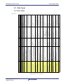
2.7.4.1 DS containing normal data
The DSs are stored according to the following picture:
byte 1
Figure 2-13
byte 0
SOR
EOP
EOR0
EOR1
REF entry Data n-2
DRP
DCS
SOR
EOP
EOR0
EOR1
REF
Zone
REF entry Data n-1
DRP
DCS
SOR
EOP
EOR0
EOR1
REF entry Data n
DRP
DCS
Blank / Fill zone
Data n (14 Bytes)
Data
Zone
Data n-1 (4 Bytes)
Data n-2 (3 Bytes)
DS Data and management information in Flash
R01AN1035ED0100 Rev. 1.0
Application Note
25
EEPROM Emulation Library
•
Architecture
SOR - Start of reference entry
It is written 1st in order to block one REF zone list entry.
•
DRP - Data Reference Pointer
Is written after SOR and contains:
- 16-bit lower half word: ID
- 16-bit upper half word: word index, a pointer to the data
DRP can address 64k indexes. This is sufficient to cover 128kB Flash with
HWd addressing (indexing).
Note
•
EOP - End of DRP
Is written immediately after the DRP. When written, the read margin of the
DRP word is ensured by the write sequence.
•
DCS - Data Check Sum
This is a simple 16bit checksum, calculated over the user data and DRP. It
ensures higher robustness (detection) on accidental overwriting of data or
DRP.
The DRP widx is excluded from the checksum as it is updated in case of a
Refresh, where the DCS is not re-calculated (may not be recalculated as in
case of an application update combined with IDL table update, the DCS
indicates a possible DS length change to the user application).
Note
•
EOR0 - End of Reference 0
EOR0/1 are the last written HWds of a DS. When EOR0 pattern is correct, it
is ensured that the previously written REF entry part and data are written
correct
•
EOR1 - End of Reference 1
Additional safety for the case of data set write interruptions.
At the end of the startup phase EOR1 is checked for each DS and on not
available or invalid EOR1 the DS is refreshed to ensure the electrical margin
of the complete DS
2.7.4.2 Invalidated DS
One requirement is to provide a possibility to invalidate the last DS instance of a
certain ID.
Sample use case: When activating a window lifter, the last stored window
position is invalidated, then the lifter is turned on. At the end when the lifter stops
the new position is written.
Invalidation is realized by a special kind of REF entry. The widx entry is set to
zero and no data is written in the data zone.
A later on Read on this ID will return an error EEL_ERR_NO_INSTANCE to
indicate this non existing data.
R01AN1035ED0100 Rev. 1.0
Application Note
26
EEPROM Emulation Library
EEL Design
Chapter 3 EEL Design
3.1 Asynchronous architecture
Each state has a strictly limited execution time. Based on that, the library function
controlling the state machine (EEL_Handler, see API description) will
immediately return to the user application. Due to dual operation between Code
Flash and Data Flash the upper application can continue operation while
frequently invoking the state machine handler function.
3.2 Flash interrupt support
The EEL is prepared to support the Flash interrupt. This means, that the EEL
triggers the Flash interrupt when the handler function shall be called in order to
process a next EEL process state. By that, the handler function can be executed
in the Flash interrupt context or in an interrupt triggered task which means as few
as possible handler function calls (no polling) by achieving the best EEL
performance.
Basically, each Flash operation end triggers the Flash interrupt. However, quite
some EEL state machine internal states (User operations as well as background
processes) don’t issue a Flash operation. In order to support the Flash interrupt
in a sufficient way, these states must issue the Flash interrupt by SW. This can
be achieved by the EEL configuration (See 5.1, “Pre-compile configuration”).
Note Even when the EEL is idle, the handler function shall be called regularly in order
to execute idle time supervision tasks like bit error check (See 3.4, “Background
operations”). As for that the handler shall not be called with high frequency (e.g.
10ms~100ms task), the user application need to trigger the interrupt by SW.
3.3 EEL user operations priority
The EEL provides the following user operations which are invoked by appropriate
commands: Immediate DS Write, Immediate DS Invalidate, DS Write, DS
Invalidate, DS Read, Format, Cleanup. These commands have partially been
mentioned before and are described in the API description.
The Read and Write operations are considered to be prioritized according to the
following scheme:
•
Priority 1
Read, can interrupt Write, Incremental Write, Invalidation, Immediate Write,
Immediate Incremental Write and Immediate Invalidation
•
Priority 2
Immediate Write Immediate Incremental Write and Immediate Invalidation
can interrupt Write, Incremental Write and Invalidation
•
Priority 3
Write, Incremental Write and Invalidation cannot interrupt any other user
operation
The following rules apply to these operations:
All of the above operations can interrupt ongoing background operations.
A command invoking an operation when an operation of the same priority is
ongoing will be rejected.
When an operation of a higher priority is invoked, a possibly ongoing operation of
a lower priority will be suspended.
R01AN1035ED0100 Rev. 1.0
Application Note
27
EEPROM Emulation Library
EEL Design
When invoking an operation of a lower priority, a possibly ongoing operation of a
higher priority is will be finished first then the lower priority operation is executed.
Furthermore, special conditions apply for the other operations:
•
Format operation
Requires that the system executes no user or background operations. If this
is not the case, the command will be rejected. When started, all other
operations are blocked.
•
Cleanup operation
Requires that the system executes no user or background operations. If this
is not the case, the command will be rejected.
After being started other operations can be executed, the cleanup operation
will be suspended and later on resumed automatically.
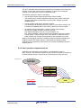
3.4 Background operations
The EEL operations are based on independent processes for the different user
operations, such as Read, Write, Immediate Write. Furthermore, background
processes are to be executed in order to manage the EEL pool and to manage
the startup flow.
The following background operations and their processes are available:
•
Refresh
This process manages copying any potential DS instances from the EEL pool
active tail to the head before invalidating a virtual block. The copy process
itself is done by the Write (Refresh) process. After invalidation, the block can
be prepared again.
•
Write (Refresh)
This process is triggered by Refresh to copy one DS
•
Prepare
Erase invalid Flash blocks and mark them prepared. This process provides
new space for the active pool.
•
Supervision
This process manages the complete startup processing (See 3.7, “Start-up
processing”). When the library is up and in normal operation, it controls the
background processes:
o
When the refresh threshold is underrun, the process triggers first the
Refresh process, then the Prepare process to provide enough prepared
pool space to store new DS instances.
o
When no further pool handling is required, the process checks the EEL
pool for bit errors. To do so, the complete pool address range (only
active and prepared virtual blocks) is checked HWd by HWd using the
FDL bit error check function. On detection of a bit error, further Refresh
and Prepare operations are triggered and by that, sequentially all blocks
are refreshed. This is continued until the bit error is gone.
On invocation of a user operation, the background processes are interrupted at
the next possible state in order to execute the user processes. After user process
termination, the background processes are continued.
Note When the Supervision process need not execute any pool operations beside bit
error check, the EEL driver status is set to idle. Nevertheless, the handler
function shall be called regularly (even with lower frequency, e.g. 10ms task) in
order to execute the bit error checks. This need to be considered too, when the
library is executed in the Flash interrupt context.
R01AN1035ED0100 Rev. 1.0
Application Note
28
EEPROM Emulation Library
EEL Design
3.5 Error and warning levels
Due to the case, that errors may happen in cause of user activated processes
(e.g. write, read, format) or automatic handled background processes (prepare,
refresh, supervision), the error return to the user and the complete system
reaction on the errors must be clearly defined.
The error reaction is classified in the (5.3.1, “Error Codes”):
•
Warnings, e.g. EEL_ERR_BLOCK_EXCLUDED
These warnings are signalled to the user application but don’t result in a
emulation system reaction.
•
Errors resulting in complete system lock, e.g.
EEL_ERR_POOL_INCONSISTENT
The error is signalled to the user application and the complete system is
locked:
•
o
No user commands accepted.
o
All ongoing user operations are stopped and return with error
EEL_ERR_ACCESS_LOCKED.
o
All background processes are stopped.
Errors resulting in read only mode, e.g. EEL_ERR_FLASH_ERROR during
data set write:
The error is signalled to the user application and the complete system is in
read only mode:
o
Only further user read command accepted, write and format are locked.
o
All ongoing user operations are stopped and return with error
EEL_ERR_ACCESS_LOCKED (a read operation cannot be ongoing as
this has the highest priority).
o
All background processes are stopped.
The errors/warnings are returned to the user application on two different ways:
•
Errors on background operations are returned by a special function returning
the driver status. Independently, in case of errors, ongoing and future user
commands will be answered with EEL_ERR_ACCESS_LOCKED.
•
Errors on user commands (Write, Read, Format) will be returned as
command answer.
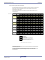
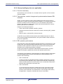
3.6 Data Set search and read
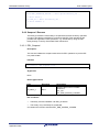
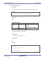
3.6.1 ID-L and IDX tables
The library uses internal tables to store the DS size information and latest DS
location.
While the DS size is stored together with the ID statically in ROM, the pointers to
the latest DS instances are evaluated on library startup and stored in RAM.
R01AN1035ED0100 Rev. 1.0
Application Note
29
EEPROM Emulation Library
EEL Design
Figure 3-1
Library ID Tables
The ID-L table (ROM table) contains one entry for each ID available in the
system, together with its DS length information. This table is configured at
compile time.
IDX table (RAM table) contains for each ID available in the system the pointer to
the latest data instance. On EEL startup the IDX table is filled and continuously
updated on each DS Write access.
3.6.1.1 Data Read Mechanisms
ROM table search
Whenever a DS with a dedicated ID shall be read, the requested ID is searched
in the ROM table. The index of the ROM table entry with the fitting ID is then
used to get the data pointer (to the Data Flash) from the RAM table.
This ROM table search is fast, but the RAM table must be initialized on startup
which requires some time.
The Rom table is used for Read as well as for the Refresh process.
REF zone search
In order to be able to read data without initialized RAM table, the library provides
another read (data search) mechanism. The library can parse the REF zone of
the blocks and read the entries sequentially until an entry with the requested ID is
found. It needs to be considered, that the REF zone parsing requires some time
and 100% CPU load.
This search mechanism is called REF-zone search.
The REF zone search is used in the library startup phase, when the RAM table is
not yet initialized and also in special library operation modes (see next subchapter).
R01AN1035ED0100 Rev. 1.0
Application Note
30
EEPROM Emulation Library
EEL Design
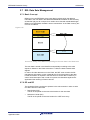
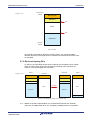
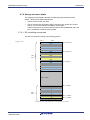
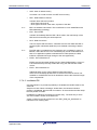
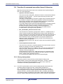
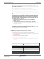
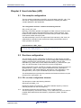
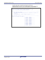
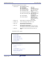
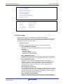
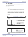
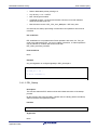
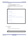
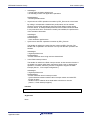
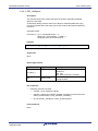
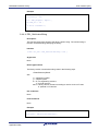
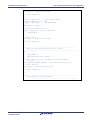
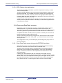
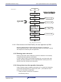
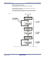
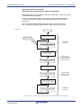
3.7 Start-up processing
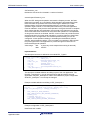
The start-up processing is controlled by the EEL state machine. After library
initialization and start-up invocation (see EEL_Startup function API), several
start-up process steps are executed until the system is in normal operation.
Along with the start-up progress the access rights to the data and the library
features are unlocked and the full performance of the EEL is reached.
The start-up progress can be checked by the user application with the function
EEL_GetDriverStatus which returns the access status and the operational status.
Please check the next figure for the status values depending on the progress:
Start-up
progress
access status
operational status
comment
EEL_ACCESS
_LOCKED
EEL_ACCESS
_LOCKED
EEL_OPERATION
_PASSIVE
EEL_OPERATION
_STARTUP
EEL startup
ongoing basic startup
finished
EEL_ACCESS
_READ_WRIT
E
EEL_OPERATION
_STARTUP
EEL startup
ongoing RAM table
filled
EEL_ACCESS
_UNLOCKED
EEL_OPERATION
_STARTUP
All library operations
are prevented.
All library operations
are prevented.
DS Read is possible
with limited
performance (REF
zone search).
DS Write is possible
until the prepared
blocks are full.
DS Read is possible
with full performance
(ROM table search).
DS Write is possible
and supervision
processing is active to
manage the ring buffer.
EEL_ACCESS
_UNLOCKED
EEL_OPERATION
_BUSY or _IDLE
(depending if
Refresh/Prepare
operations are to
be done)
EEL Initialized
EEL startup
started
EEL startup
end
- DS Read and DS
Write as before
- Electrical margin of
the latest DS instances
is ensured.
Startup process progress steps
In case of a fatal error during any start-up step, the library switches to
EEL_ACCESS_LOCKED and EEL_OPERATION_PASSIVE and the function
EEL_GetDriverStatus will additionally return an appropriate error.
Note The last startup processing step (Ensure the electrical margin of the latest DS
instances) checks if the valid DS instances have been completely written.
Therefore it checks if the last step of a DS write was executed (EOR1 is written).
If not, redundant information (valid EOR0) ensures that the DS data is valid. On
detection of such cases, the DS is refreshed (copied to active zone head).
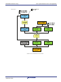
R01AN1035ED0100 Rev. 1.0
Application Note
31
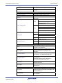
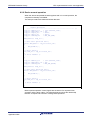
R01AN1035ED0100 Rev. 1.0
Application Note
0
is00
is01
Get Block Status
RESET
1
is0n
is10
2
is1m
EEL_ACCESS_LOCKED
is11
Check Ring buffer
consistency
is31
is3m
EEL_OPERATION_STARTUP
3
is2m
is20
is21
is30
Init ring buffer
variables &
check pool full
Get pointers
is40
30
is41
isx2
isxy
Operational
level
EEL_OPERATION_BUSY
EEL_OPERATION_IDLE
EEL_ACCESS_UNLOCKED
Access level
t[ms]
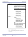
is<xy>: internal library state machine states
(starting with
ensuring DS margin)
Permanent
supervision
isx1
Limited Write access & Limited
Read access enabled
is4m
EEL_ACCESS_READ_WRITE
Build RAM
table
isx0
Fully operational
(after DS margins ensured)
EEPROM Emulation Library
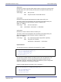
EEL Design
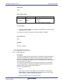
Figure 3-2
Start-up processing steps
32
EEPROM Emulation Library
EEL Design
3.8 Function & command execution times & latencies
Basically three important times need to be considered when implementing the
EEL into a user application:
•
Operation invocation latency
This is the time from calling EEL_Execute to issue the command and start an
operation (e.g. Read, Write, ...) up to the point where the process of the
operation is really started.
This latency is determined by execution of higher priority operations but also
by the delay to suspend a lower priority operation. Some process steps of
lower priority operations cannot be suspended because they started Flash
Write operations (erase can immediately be suspended).
E.g. the DS Write process cannot be suspended until the user data write has
started (After SOR, DRP, EOP write and potential new block activation)
because otherwise the data consistency would be endangered.
So, these process steps must be finished and by this determine the
invocation latency of a higher priority operation.
•
EEL_Handler/EEL_Execute execution time
The execution time should be typically below 100us on a 100MHz device in
order to realize a system with reliable timing. During normal operation this
can be reached, but in the startup phase the execution times will be longer as
complex calculations and searches are executed. In the startup phase this
time is affected by many conditions and so can only be measured for a
reference system, whereas the real timing needs to be evaluated by the
customer in the user application.
Issues affecting this time are e.g. DS Size, higher priority operations ongoing,
pool size,...
•
Overall operation execution time
This is the time to execute a complete operation, like user DS write, user DS
Read from operation invocation to operation finish.
This time is affected by many conditions and so can only be measured for a
reference system, whereas the real timing needs to be evaluated by the
customer in the user application.
Issues affecting this time are e.g. Flash Write time (in the evaluations also
the worst case time need to be considered), DS Size, operation invocation
latency, higher priority operations ongoing, ...
So, in the next sub-chapters this time is not mentioned again.
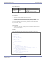
3.8.1 Library startup phase
The library needs to execute various process steps according to the
implementation concept (see startup phase description). The EEL_Handler
execution time during steps will be partially >>100us, which need to be
considered in the library implementation concept.
Note From EEL implementation point of view the startup phase will end when the
operational status changes from EEL_OPERATION_STARTUP to
EEL_OPERATION_BUSY/IDLE. Then all startup operations are finished.
From timing point of view, the startup phase will end when the access status
changes from EEL_ACCESS_READ_WRITE to EEL_ACCESS_UNLOCKED.
The remaining startup operations are executed in background and transparent for
the user. Also the early Read (see below) ends on EEL_ACCESS_UNLOCKED.
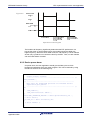
R01AN1035ED0100 Rev. 1.0
Application Note
33
EEPROM Emulation Library
EEL Design
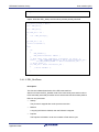
3.8.1.1 Early Read command
Operation invocation latency
The maximum latency of the Read operation invocation by the EEL_Execute
function is defined by the EEL_Handler execution time (see comments above).
Furthermore, after invocation of the read, start of the Read process need to wait
for the end of a possibly started 4-HWd Data Flash write (up to 4 half words can
be written by the Flash hardware in sequence without software interaction)
caused by a Write command or by the startup process.
EEL_Handler execution time
A Read command executed in the library startup phase while the RAM table is
not (completely) filled is called early read. The data of a DS with a certain ID to
be read is found as follows:
•
If the ID-X RAM table entry belonging to the ID is already filled, the entry
addresses the data and the data can be read quickly.
•
If the ID-X RAM table entry belonging to the ID is not yet filled, the DS is
searched by parsing the REF entries from the youngest one backwards until
a valid DS with the ID is found.
According to the possibly necessary REF entry parsing, the early Read may last
longer time (>>100us) and requires 100% CPU load.
Furthermore, the data read from Flash itself together with the checksum
calculation need some time. So, the time can increase 100us already by DS
sizes > 32 Bytes
3.8.1.2 Early Immediate Write / Immediate Incremental Write / Immediate
Invalidation command
The early Immediate Write sequence does not differ to the normal Immediate
Write.
Generally, a Write operation needs to wait for the end of a preceding Write or
Invalidation operation. Trying to invoke a Write before will be rejected.
Operation invocation latency
The maximum latency of the Write operation invocation by the EEL_Execute
function is defined by the EEL_Handler execution time (see comments above).
Furthermore, after invocation of the write, starting of the Write/Invalidation
process need to wait for:
•
The end of a higher priority Read command.
•
The end of blocking by a lower priority DS Write process invoked by user DS
Write/Invalidation command or background Refresh process. In order to
ensure data and ring buffer consistency, any DS Write process need to block
higher priority Write commands until the process step to write the user data is
reached. Blocking time is defined by 8 times a 1-word Data Flash Write (4times to write SOR, DRP, EOP & 4 times to possibly activate a new block).
EEL_Handler execution time
The execution time should be <100us on a 100MHz device.
R01AN1035ED0100 Rev. 1.0
Application Note
34
EEPROM Emulation Library
EEL Design
3.8.1.3 Early Write / Incremental Write / Invalidation command
The early Write sequence does not differ to the normal Write.
Generally, a Write operation needs to wait for the end of a preceding Write or
Invalidation operation. Trying to invoke a Write before will be rejected.
Operation invocation latency
The maximum latency of the Write operation invocation by the EEL_Execute
function is defined by the EEL_Handler execution time (see comments above).
Furthermore, after invocation of the write, starting of the Write process need to
wait for:
•
The end of a higher priority Read, Immediate Write or Immediate Invalidation
command.
•
The end of blocking by a lower priority DS Write process invoked by user DS
Write/Invalidation command or background Refresh process. In order to
ensure data and ring buffer consistency, any DS Write process need to block
higher priority Write commands until the process step to write the user data is
reached. Blocking time is defined by 6 times a 1-HWd Data Flash Write (4times to write SOR, DRP, EOP & 4 times to possibly activate a new block).
EEL_Handler execution time
The execution time should be <100us on a 100MHz device.
3.8.2 Normal operation phase
If not mentioned otherwise, in the normal operation phase the EEL_Handler
function execution time should always below 100us on a 100MHz device.
An ongoing Flash erase will not block any user command. The erase will be
suspended and later on resumed. Anyhow, after a configurable number of times
suspending, the warning EEL_ERR_ERASESUSPEND_OVERFLOW is returned
in order to inform the user to give sufficient time to complete the erase operation
rather than extremely frequently invoking Read/Write/Invalidation operations.
3.8.2.1 Read command
Operation invocation latency
The maximum latency of the Read operation invocation by the EEL_Execute
function is defined by the EEL_Handler execution time (see comments above).
Furthermore, after invocation of the read, start of the Read process need to wait
for the end of a possibly started 4-HWd Data Flash write (up to 4 half words can
be written by the Flash hardware in sequence without software interaction)
caused by a Write command or by the background process.
EEL_Handler execution time
Typically the handler execution time will be below 100us.
However, the data read from Flash itself together with the checksum calculation
need some time. So, the time can increase 100us by DS sizes > 32 Bytes.
R01AN1035ED0100 Rev. 1.0
Application Note
35
EEPROM Emulation Library
EEL Design
3.8.2.2 Immediate Write / Immediate Incremental Write / Immediate
Invalidation command
The normal operation Immediate Write and Immediate Invalidation sequence
does not differ to the early Immediate Write/Invalidation. So please refer to this
description.
3.8.2.3 Write / Incremental Write / Invalidation command
The normal operation Write/Invalidation sequence does not differ to the early
Write/Invalidation. So please refer to this description.
3.8.2.4 Format command
The Format command is considered as an exclusive command and can only be
executed if the background state machine is EEL_OPERATION_IDLE or
EEL_OPERATION_PASSIVE. So, invocation by EEL_Execute is rejected until
this state is reached.
Operation invocation latency
The operation is invoked without latency as no other operations are ongoing.
EEL_Handler execution time
The handler execution time will be below 100us.
3.8.2.5 Cleanup command
The Cleanup command is considered as an exclusive command and can only be
executed if the background state machine is EEL_OPERATION_IDLE. So,
invocation by EEL_Execute is rejected until this state is reached.
Operation invocation latency
The operation is invoked without latency as no other operations are ongoing.
EEL_Handler execution time
The Cleanup command only sets a variable to more often call the Refresh
process and Prepare process in background. The handler execution time will be
below 100us.
R01AN1035ED0100 Rev. 1.0
Application Note
36
EEPROM Emulation Library
Implementation
Chapter 4 Implementation
4.1 File structure
The library is delivered as a complete compile-able sample project which
contains the EEL and FDL libraries and in addition to an application sample to
show the library implementation and usage in the target application.
The application sample initializes the EEL and does some dummy data set Write
and Read operations.
Differing from former EEPROM emulation libraries, this one is realized not as a
graphical IDE related specific sample project, but as a standard sample project
which is controlled by make files.
Following that, the sample project can be built in a command line interface and
the resulting elf-file can be run in the debugger.
The FDL and EEL files are strictly separated, so that the FDL can be used
without the EEL. However, using EEL without FDL is not possible.
The delivery package contains dedicated directories for both libraries containing
the source and the header files.
Note The application sample does not contain sample code for the FDL interface
usage, but only for the EEL interface. Anyhow, as the EEL contains FDL
functions calls, the usage of the FDL functions can be derived from that.
4.1.1 Overview
The following picture contains the library and application related files.
Figure 4-1
Library and application file structure
R01AN1035ED0100 Rev. 1.0
Application Note
37
EEPROM Emulation Library
Implementation
The library code consists of different source files, starting with FDL/EEL_... The
files may not be touched by the user, independently, if the library is distributed as
source code or pre-compiled.
The file FDL/EEL.h is the library interface functions header file.
The file FDL/EEL_Types.h is the library interface parameters and types header
file.
In case of source code delivery, the library must be configured for compilation.
The file FDL/EEL_Cfg.h contains defines for that. As it is included by the library
source files, the file contents may be modified by the user, but the file name may
not.
FDL/EEL_Descriptor.c and FDL/EEL_Descriptor.h do not belong to the libraries
themselves, but to the user application. These files reflect an example, how the
library descriptor ROM variables can be built up which need to be passed with
the functions FDL/EEL_Init to the FDL/EEL for run-time configuration (see FDL
user manual and 5.4.1.1, “EEL_Init”).
•
The structure of the descriptor is passed to the user application by
FDL/EEL_Types.h.
•
The value definition should be done in the file FDL/EEL_Descriptor.h.
•
The constant variable definition and value assignment should be done in the
file FDL/EEL_Descriptor.c.
If overtaking the files FDL/EEL_Descriptor.c/h into the user application, only the
file FDL/EEL_Descriptor.h need to be adapted by the user, while
FDL/EEL_Descriptor.c may remain unchanged.
4.1.2 Delivery package directory structure and files
The following table contains all files installed by the library installer.
•
Files in red belong to the build environment, controlling the compile, link and
target build process
•
Files in blue belong to the sample application
•
Files in green are description files only
•
Files in black belong to the FDL and EEL (in the separate directories for EEL
and FDL)
[root]
Release.txt
Installer package release notes
[root]\[make]
GNUPublicLicense.txt
Make utility license file
libiconv2.dll
DLL-File required by make.exe
libintl3.dll
DLL-File required by make.exe
make.exe
Make utility
[root]\[<device name>]\[compiler]
Build.bat
Batch file to build the application sample
R01AN1035ED0100 Rev. 1.0
Application Note
38
EEPROM Emulation Library
Implementation
Clean.bat
Batch file to clean the application sample
Makefile
Makefile that controls the build and clean
process
[root]\ [<device name>]\[<compiler>]\[sample]
EELApp_Main.c
Main source code
EELApp_Control.c
EEPROM emulation sample code
target.h
target device and application related
definitions
df<device number>.h
GHS
df<device number>_irq.h
io_macros_v2.h
device header files
io_70f< device number>.h
IAR
io_macros.h
lxx.h
cfi.h
GHS
start-up file
linker directive file
IAR
DF<dev. num.>_startup.850
l07.s85
cstartup.s85
REC
cstart.asm
GHS
df<dev. num.>.ld
IAR
lnk70f<dev. num.>.xcl
REC
df<dev. num.>.dir
[root]\ [<device name>]\[<compiler>]\[sample]\[FDL]
Header file containing function prototypes of
FDL.h
the library user interface.
FDL_Types.h
Header file containing calling structures and
error enumerations of the library user
interface.
FDL_Descriptor.h
Descriptor file header with the run-time FDL
configuration. To be edited by the user.
FDL_Descriptor.c
Descriptor file with the run-time FDL
configuration.
Using the defines of FDL_Descriptor.h.
Should not be edited by the user.
FDL_User.c
Library related functions, which may be
edited by the user
FDL_Cfg.h
Header file with definitions for library setup at
compile time.
[root]\ [<device name>]\[<compiler>]\[sample]\[FDL]\[lib]
Library internal defines for accessing the
FDL_Env.h
Flash programming hardware and Data Flash
related definitions.
FDL_Global.h
R01AN1035ED0100 Rev. 1.0
Application Note
Library internal defines, function prototypes
and variables.
39
EEPROM Emulation Library
Implementation
FDL_HWAccess.c
Source code for the library Hardware
interface.
FDL_UserIF.c
Source code for the library user interface and
service functions.
[root]\ [<device name>]\[<compiler>]\[sample]\[EEL]
Header file containing all function prototypes
EEL.h
of the library user interface.
EEL_Types.h
Header file containing calling structures and
error enumerations of the library user
interface.
EEL_Cfg.h
Header file with definitions for library setup at
compile time.
EEL_Descriptor.c
Descriptor file with the run-time EEL
configuration.
Using the defines of EEL_Descriptor.h and
should not be edited by the user.
EEL_Descriptor.h
Descriptor file header with the run-time EEL
configuration. To be edited by the user.
[root]\ [<device name>]\[<compiler>]\[sample]\[EEL]\[lib]
Library internal defines, function prototypes
EEL_Global.h
and variables
EEL_BasicFct.c
EEL internal functions & state machine
EEL_UserIF.c
EEL user interface functions
4.2 EEL Linker sections
The following sections are EEPROM emulation library related:
•
FAL_Text
FDL code section, containing the hardware interface and user interface.
•
FAL_Const
FDL data section, containing library internal constant data
•
FAL_Data
FDL Data section containing all FDL internal variables
•
EEL_Text
EEL code section containing the state machine, user interface and FAL
interface
•
EEL_Const
EEL data section, containing library internal constant data
•
EEL_Data
EEL Data section containing all EEL internal variables
R01AN1035ED0100 Rev. 1.0
Application Note
40
EEPROM Emulation Library
Implementation
4.3 MISRA Compliance
The EEL and FDL have been tested regarding MISRA compliance.
The used tool is the QAC Source Code Analyzer which tests against the MISRA
2004 standard rules.
All MISRA related rules have been enabled. Findings are commented in the code
while the QAC checker machine is set to silent mode in the concerning code lines.
R01AN1035ED0100 Rev. 1.0
Application Note
41
EEPROM Emulation Library
User Interface (API)
Chapter 5 User Interface (API)
5.1 Pre-compile configuration
The pre-compile configuration of the EEL may be located in the EEL_cfg.h. The
user has to configure all parameters and attributes by adapting the related
constant definition in that header-file.
The configuration for Fx4-L contains the following element:
EEL_FLINT_SET_SW:
Basically, each Flash operation end triggers the Flash interrupt. However, quite
some EEL state machine internal states don’t issue a Flash operation. If the
handler function shall be executed in the Flash interrupt context, these states
must issue the Flash interrupt by SW.
The define basically is a macro to request the Flash interrupt by SW. If set, it is
called within the handler function at the end of each process state, when no
Flash operation was started.
Implementation in EEL_Cfg.h:
#define EEL_FLINT_SET_SW ( ( *(eel_u16*)0xffff60feuL ) =
( *(eel_u16*)0xffff60feuL ) | 0x1000 )
5.2 Run-time configuration
The overall EEL run-time configuration is defined by an EEL specific part (EEL
run-time configuration) and by the FDL run-time configuration. Background of the
splitting is that the FDL requires either common, by EEL and FDL used
information (e.g. block size) or EEL related information (e.g. about the EEL pool
size). So, this information is part of the FDL run-time configuration.
Both configurations of FDL and EEL are stored in descriptor structures which are
declared in FDL_Types.h / EEL_Types.h and defined in FDL_Descriptor.c /
EEL_Descriptor.c with header files FDL_Descriptor.h / EEL_Descriptor.h. The
descriptor files (.c and .h) are considered as part of the user application.
The defined descriptor structures are passed to the libraries as reference by the
functions FDL_Init and EEL_Init.
5.2.1 FDL run-time configuration elements
The descriptor contains the following elements.
falFrequencyCpuMHz_u16:
Defines the device CPU frequency. The Flash hardware frequency is device
internally derived from the CPU frequency.
Note The define requires the CPU frequency, not the crystal frequency!
The CPU frequency must be set correctly. If not, malfunction may occur such as
unstable Flash data without data retention, programming failure, operation
blocking.
R01AN1035ED0100 Rev. 1.0
Application Note
42
EEPROM Emulation Library
User Interface (API)
falPoolSize:
Defines the number of physical Flash blocks used for the FAL pool, which means
the User Pool + EEL Pool. Usually, the FAL pool size equals the total number of
Flash blocks.
Value range:
Min:
EEL pool size
Max:
Physical number of Data Flash blocks
eelPoolStart:
Defines the first physical Data Flash block number used as EEL pool.
The block number must be aligned to the virtual block size (2kB) used by the
EEL! Following that, the block number must be a multiple of 64
(2kB = 64 * 32Byte)
Value range:
Max:
Min:
FAL Pool start block
eelPoolStart + eelPoolSize <= falPoolSize
eelPoolSize:
Defines the number of blocks used for the EEL pool.
The block number must be aligned to the virtual block size (2kB) used by the
EEL! Following that, the block number must be a multiple of 64
(2kB = 64 * 32Byte)
Value range:
Min:
64 * 4 Blocks (required for proper EEL operation)
Max:
FAL pool size, condition:
eelPoolStart + eelPoolSize <= falPoolSize
Implementation:
The descriptor structure is defined in the module FDL_Types.h
typedef struct FAL_DESCRIPTOR_T {
fal_u16 falFrequencyCpuMHz_u16;
fal_u16 falPoolSize_u16;
fal_u16 eelPoolStart_u16;
fal_u16 eelPoolSize_u16;
} fal_descriptor_t;
The descriptor variable definition and filling is part of the user application. The
files FDL_Descriptor.h/.c give an example which shall be used by the user
application. Only FDL_Descriptor.h need to be modified for proper configuration
while FDL_Descriptor.c can be kept unchanged.
Example variable definition and filling in FDL_Descriptor.c:
const fal_descriptor_t eelApp_falConfig_enu =
{
FAL_CPU_FREQUENCY_MHZ,
FAL_FAL_POOL_SIZE,
FAL_EEL_POOL_START,
FAL_EEL_POOL_SIZE
};
R01AN1035ED0100 Rev. 1.0
Application Note
43
EEPROM Emulation Library
User Interface (API)
Example configuration in FDL_Descriptor.h:
Example 1)
Data Flash size is 32kB.
The EEL shall use the complete Data Flash for the EEL pool:
#define FAL_EEL_VIRTUALBLOCKSIZE 64u
#define FAL_FAL_POOL_SIZE
#define FAL_EEL_POOL_START
#define FAL_EEL_POOL_SIZE
16u * FAL_EEL_VIRTUALBLOCKSIZE
0u * FAL_EEL_VIRTUALBLOCKSIZE
16u * FAL_EEL_VIRTUALBLOCKSIZE
Example 2)
Data Flash size is 32kB.
The EEL shall use blocks 2 to 9 for the EEL pool, while blocks 0 to 1 and 10 to 15
can be used as user pool:
#define FAL_EEL_VIRTUALBLOCKSIZE 64u
#define FAL_FAL_POOL_SIZE
#define FAL_EEL_POOL_START
#define FAL_EEL_POOL_SIZE
16u * FAL_EEL_VIRTUALBLOCKSIZE
2u * FAL_EEL_VIRTUALBLOCKSIZE
8u * FAL_EEL_VIRTUALBLOCKSIZE
Example 3)
Data Flash size is 32kB; the EEL shall not be used at all. The complete Data
Flash shall be used as user pool:
#define FAL_EEL_VIRTUALBLOCKSIZE 64u
#define FAL_FAL_POOL_SIZE
#define FAL_EEL_POOL_START
#define FAL_EEL_POOL_SIZE
16u * FAL_EEL_VIRTUALBLOCKSIZE
0u * FAL_EEL_VIRTUALBLOCKSIZE
0u * FAL_EEL_VIRTUALBLOCKSIZE
5.2.2 EEL run time configuration elements
The descriptor contains the following elements:
addDF
Defines the Data Flash start address in the physical address room. The definition
is required for EEL internal calculations.
This is just a configuration option reserved for future use. In all current Devices
the Data Flash address is fixed.
Value range:
R01AN1035ED0100 Rev. 1.0
Application Note
Fixed to 0xFE00000
44
EEPROM Emulation Library
User Interface (API)
blkRefreshThreshold
Defines the number of virtual blocks that shall be prepared in the ring buffer by
default. In case of threshold underflow, the EEL supervision will initiate Refresh /
Prepare operations to cleanup the active EEL pool range and provide more
prepared blocks by time until the threshold is exceeded again.
Increasing the threshold allows fast sequences of data write without having to
give the EEL time to do the Refresh/Prepare operations. Reducing the threshold
improves the Flash usage as written data sets stay longer in the ring buffer and
need less Refresh copy operations. When the threshold is set too low and the
ring buffer gets full due to continuous data set write, the library will return error
Pool Full and block further write operations until the supervision had enough time
to prepare at least one additional Flash block.
Value range:
Min:
2 Blocks (required for proper EEL operation)
Max:
EEL pool size – 2
Example:
On a threshold of 6 the EEL will always try to have 6 prepared blocks as passive
pool in the ring buffer. This means that the user application could write 10kB data
in sequence without giving the EEL time to do background operations to prepare
new space again (one block must remain prepared for pool full situation handling).
~1/3 of the total available Flash blocks might be a reasonable starting point to
evaluate the balance between the possibility to write fast data sequences (big
threshold) and reducing the data copy effort on refresh (low threshold). The
service function EEL_GetSpace provides a tool to trace the available free space
in the ring buffer during run-time which allows threshold optimization during runtime.
*IDLTab_pau16
Pointer to ROM ID-L table (See chapter 3.6.1, ”ID-L and IDX tables”)
The ID-L table need to be defined as a 2-dimensional array of 16bit values as
follows:
{ { ID1, size 1 }, { ID2, size 2 }, { ID3, size 3 }, ..... }
Value range:
ID Min:
ID Max:
Size min:
Size max:
1
0xFFFE
1Byte
Block size – Block header size
– REF zone size - 2
= 2048 – 36 – 14 - 2
= 1996 Bytes
(this is caused by the EEL implementation.
Bigger data size would require significant
overhead in the power fail and supervision
concepts).
*IDXTab_pau16
Pointer to ROM ID-X table (See chapter 3.6.1, ”ID-L and IDX tables”)
The ID-X table is a 1-dimensional array of 16bit values. The ID-X table RAM is
provided by the user application and filled and handled by the EEL.
R01AN1035ED0100 Rev. 1.0
Application Note
45
EEPROM Emulation Library
User Interface (API)
IDLTabIdxCnt_u16
Defines the size of the ID-L/X table in “number of entries”.
eraseSuspendThreshold_u16
When the EEL background operation executes the Prepare process, the Data
Flash block is erased. Any user Read or Write operation will suspend the Flash
Erase and after the operation resume the Erase again. Based on the Flash
implementation, this Erase Suspend/Resume flow is restricted. The Erase
operation might not finish, if it is interrupted continuously. The user application
must be realized in a way that the erase operation once gets the time to complete,
which means that the user application must provide a time frame as long as the
worst case Flash block erase time in which the erase operation is not suspended.
As long as the erase is not finished, the EEL cannot continue to provide new free
passive pool space for further write operations. In order to signal too often Erase
suspends to the user application, the eraseSuspendThreshold_u16 can be
configured. A user operation resulting in exceeding the threshold will return a
warning “erase suspend overflow”. This is no hard error resulting in EEL reaction
but just a signal to the user application to provide enough time to the EEL to
finish the background operation.
Value range:
Min:
Max:
0 (On every erase suspend the warning is returned)
0xFFFF
Implementation:
The descriptor structure is defined in the module EEL_Types.h
typedef struct EEL_DESCRIPTOR_T {
eel_u32
addDF_u32;
eel_u16
blkRefreshThreshold_u16;
const eel_u16
(*IDLTab_pau16)[2];
eel_u16
*IDXTab_pau16;
eel_u16
IDLTabIdxCnt_u16;
eel_u16
eraseSuspendThreshold_u16;
}
eel_descriptor_t;
The descriptor variable definition and filling is part of the user application. The
files EEL_Descriptor.h/.c give an example which shall be used by the user
application. Only EEL_Descriptor.h need to be modified for proper configuration
while EEL_Descriptor.c can be kept unchanged.
Example variable definition and filling in EEL_Descriptor.c:
const eel_u16
IDLTab_au16[][2] = EEL_CONFIG_IDL_TABLE;
eel_u16
IDXTab_au16[sizeof( IDLTab_au16 )>>2];
const eel_descriptor_t eelApp_eelConfig =
{
EEL_CONFIG_DF_BASE_ADDRESS,
EEL_CONFIG_BLOCK_CNT_REFRESH_THRESHOLD,
IDLTab_au16,
&(IDXTab_au16[0]),
( sizeof( IDLTab_au16 ) >> 2 ),
EEL_CONFIG_ERASE_SUSPEND_THRESHOLD
};
Example configuration in EEL_Descriptor.h:
Data Flash size is 32kB.
R01AN1035ED0100 Rev. 1.0
Application Note
46
EEPROM Emulation Library
User Interface (API)
The EEL shall use the complete Data Flash for the EEL pool,
blkRefreshThreshold is set to ~1/3 of 16 Flash blocks = 5, the erase shall be
suspend able up to 10 times until the erase suspend warning is issued:
#define EEL_CONFIG_DF_BASE_ADDRESS
#define EEL_CONFIG_BLOCK_CNT_REFRESH_THRESHOLD
#define EEL_CONFIG_ERASE_SUSPEND_THRESHOLD
0xfe000000
0x05
10
/*------------------------------------------------------------*/
EEL_CONFIG_IDL_TABLE
Descriptor table containing data set identifier and data set
length as:
{ { <16-bit ID>, <16-bit length in bytes> }, {...},
{...}, .... }
/*------------------------------------------------------------*/
#define EEL_CONFIG_IDL_TABLE {
{ 0x1111, 0x0005 },
\
{ 0x2222, 0x0006 },
\
{ 0x3333, 0x0007 },
\
{ 0x4444, 0x0008 },
\
{ 0x5555, 0x0009 },
\
{ 0x6666, 0x000a },
\
{ 0x7777, 0x000b },
\
{ 0x8888, 0x000c },
\
{ 0x9999, 0x000d },
\
{ 0xaaaa, 0x0015 },
\
{ 0xbbbb, 0x0018 },
\
{ 0xcccc, 0x0033 }
\
}
R01AN1035ED0100 Rev. 1.0
Application Note
47
R01AN1035ED0100 Rev. 1.0
Application Note
EEL System overload
A Read/Write operation is started and lead to a background
erase operation suspend. The Erase suspend took place so
often, that the erase could not be completed for a long time.
This error return shall be treated as warning.
The counter until the warning is configurable by the user
A command which is locked was called. Reason for locking
may be:
1) The library is not started-up far enough for a operation
2) Due to an error the library switched to passive and locks
all new operations and ongoing lower priority operations
EEE_ERR_ERASESUSPEND_OVERFLOW
EEL_ERR_ACCESS_LOCKED
EEL status & error codes
48
Current command rejected
The command to be executed is unknown
None / Warning only
EEE_ERR_COMMAND
None / Warning only
Continue EEL operation with
EEL_CMD_FORMAT -orif the result is not expected, stop EEPROM
emulation and investigate in the root cause
Stop EEPROM emulation and investigate in the
root cause
Continue operation
Continue operation
Stop EEPROM emulation and investigate in the
root cause
The Flash should be considered as defect:
- Write locked
Stop EEPROM emulation and investigate in the
root cause
Stop issuing further Write/Invalidate commands
but call the EEL_Handler frequently until the EEL
had time to prepare enough passive pool space
Continue operation -orif the result is not expected, stop EEPROM
emulation and investigate in the root cause
Continue operation -orif the result is not expected, stop EEPROM
emulation and investigate in the root cause
Stop EEPROM emulation and investigate in the
root cause
Reduce the EEL load with Read/Write operations
so that the Flash Erase has time to finish
Repeat the command when the concurrent
operation has finished
Stop EEPROM emulation and investigate in the
root cause
Stop EEPROM emulation and investigate in the
root cause
Ring buffer consistency problems
(Incomplete erased/written Flash
cells, caused e.g. by reset on power
fails) are fixed
Application bug
Recommended Application Reaction
Continue operation
Continue operation
Stop EEPROM emulation and investigate in the
root cause
The further library reaction is undefined:
- All access is locked
Hardware problem
Hardware problem
Application bug
The Flash should be considered as defect, the
library accesses are locked:
- Write locked
Hardware problem or application bug
(Error occurred during normal operation)
- Read & Write locked
(Error occurred during startup)
Current command rejected
The block consistency check of the startup routine found an
Application bug or hardware problem The Flash must be formatted:
inconsistency in the startup routine.
or intended behavior
- Read & Write locked
This error is also returned in case of blank (unformatted) Flash
A library internal error occurred, which could not happen in
case of normal program execution (E.g. Program run-away,
bug, ...)
Due to multiple Flash block exclusion no more blocks are
available for Prepare operations.
The error is very unlikely due to the Flash failure rate!
A Prepare operation excluded a block as this could not be
erased
Startup has done a consistency fix-operation. This is a normal
return value on Startup after power fail.
The sections are assumed to be consistent and emulation can
continue normally
A Flash operation of the FDL (called by EEL ) failed due to a
Flash problem.
Due to high DS Write load, no more blocks could be prepared
EEL system overload
to gain space for new data
Either no DS corresponding to the ID could be found or the
data has been invalidated explicitly (See Invalidation command Application bug or intended behavior None / Warning only
API)
The checksum of the Data Set does not match. Beside
accidental data overwrite, also a change of the IDL ROM table Application bug or hardware problem Read operation returned data, but the contents
or intended behavior
might be wrong
(data length information) during application update by a boot
loader might be the root cause
Current command / function execution is
rejected
EEL_ERR_POOL_INCONSISTENT
EEL_ERR_FIX_DONE
EEE_ERR_BLOCK_EXCLUDED
EEL_ERR_POOL_EXHAUSTED
EEL_ERR_INTERNAL
EEL_ERR_FLASH_ERROR
EEL_ERR_POOL_FULL
EEL_ERR_WRONG_CHECKSUM
EEL_ERR_NO_INSTANCE
Application bug or intended behavior Current command rejected
A new operation should be initiated although the
state machine is still busy with a concurrent operation (e.g.
EEL_CMD_READ --> EEL_CMD_READ, but not
EEL_CMD_WRITE --> EEL_CMD_READ)
EEE_ERR_REJECTED
1) Application bug
2) Application bug or hardware
problem
Current command rejected
EEE_ERR_PARAMETER
None / Warning only
The library is not initialized
EEL Operation Impact
Wrong parameters have been passed to the EEL, e.g.: Wrong
Application bug
parameter in the request structure
None
None
The EEL_Init function was called with wrong configuration data Application bug
Root Cause Judgment
EEL_ERR_CONFIGURATION
Explanation
The operation finished successfully
The operation has been started successfully
EEL_OK
EEL_BUSY
EEPROM Emulation Library
User Interface (API)
5.3 Data Types
5.3.1 Error Codes
Figure 5-1
EEPROM Emulation Library
User Interface (API)
The error code table shows quite some severe error messages, which lead to the
situation, that the EEL cannot continue operation. It needs to be considered
carefully, how to deal with the error fro application side.
The following options are worth to discussing:
•
Stop and permanently disable emulation (emulation is dead):
This mostly lead to complete application failure and the system need to be
changed. This allows a certain kind of “post mortem” analysis, but lower
availability rates
•
Format the Data Flash and re-start the emulation:
This will destroy all data and prevent any kind of “post mortem” analysis, but
increase the availability rates of the system if data loss can be accepted.
•
Re-initialize and re-start the EEL a certain number of times before
permanently disable emulation (emulation is dead):
This allows potentially to recover from some failures, e.g.
EEL_ERR_INTERNAL. While increasing the availability rates of the system,
a “post mortem” analysis will get much more difficult or impossible, as the
Flash contents may change since appearance of the problem root cause.
While in the debugging phase the emulation should be stopped immediately for
problem analysis, the system reaction in field should be carefully judged
depending on the application requirements to the system availability and failure
analysis options.
5.3.2 User operation request structure
All different user operations are initiated by a central initiation function
(EEL_Execute). All information required for the execution is passes to the EEL by
a central request structure. Also the error is returned by the same structure:
Figure 5-2
Request structure handling
R01AN1035ED0100 Rev. 1.0
Application Note
49
EEPROM Emulation Library
User Interface (API)
The following request elements are defined:
•
command_enu:
•
address_u32
Buffer address for the Read and Write operation.
•
identifier_u16:
16bit ID, identifying the DS to read or write.
•
length_u16:
Only required for Read operation:
Number of bytes to read from the DS.
•
offset_u16:
Only required for Read operation:
Read offset from the DS bottom. Together with length
the parameter is used to read only a fraction of the DS.
•
status_enu:
Status/Error codes returned by the library (see next
page).
User operation to execute:
EEL_CMD_READ
EEL_CMD_WRITE
EEL_CMD_WRITE_INC
EEL_CMD_INVALIDATE
EEL_CMD_WRITE_IMM
Read a DS
Write a DS
Incremental Write a DS
Write a DS data invalid
Write a DS with high
priority
EEL_CMD_WRITE_IMM_INC Incremental Write a DS
with high priority
EEL_EMD_INVALIDATE_IMM Write a DS data invalid
with high priority
EEL_CMD_FORMAT
Format the Data Flash
for EEPROM
EEL_CMD_CLEANUP
Clean up ring buffer to
provide as much as
possible prepared ring
buffer space
Type definition in EEL_Types.h:
typedef enum EEL_COMMAND_T {
EEL_CMD_READ,
EEL_CMD_WRITE,
EEL_CMD_WRITE_INC,
EEL_CMD_INVALIDATE,
EEL_CMD_WRITE_IMM,
EEL_CMD_WRITE_INC_IMM,
EEL_CMD_INVALIDATE_IMM,
EEL_CMD_FORMAT,
EEL_CMD_CLEANUP
} eel_command_t;
typedef enum EEL_STATUS_T {
/* Normal operation */
EEL_OK,
EEL_BUSY,
/* Warnings */
EEL_ERR_ERASESUSPEND_OVERFLOW,
EEL_ERR_WRONG_CHECKSUM,
EEL_ERR_BLOCK_EXCLUDED,
EEL_ERR_FIX_DONE,
/* Errors */
EEL_ERR_CONFIGURATION,
R01AN1035ED0100 Rev. 1.0
Application Note
50
EEPROM Emulation Library
User Interface (API)
EEL_ERR_PARAMETER,
EEL_ERR_REJECTED,
EEL_ERR_ACCESS_LOCKED,
EEL_ERR_NO_INSTANCE,
EEL_ERR_POOL_FULL,
EEL_ERR_FLASH_ERROR,
EEL_ERR_INTERNAL,
EEL_ERR_POOL_EXHAUSTED,
EEL_ERR_POOL_INCONSISTENT,
EEL_ERR_COMMAND
} eel_status_t;
typedef volatile struct EEL_REQUEST_T {
eel_u08
*address_pu08;
eel_u16
identifier_u16;
eel_u16
length_u16;
eel_u16
offset_u16;
eel_command_t
command_enu;
eel_status_t
status_enu;
} eel_request_t;
5.3.3 Driver status
The EEL supervision process collects and signals all background
operations/processes errors. Furthermore, the process controls two driver status
values which describe the status of the EEL background operations. These are
the operation status and access status:
•
Operational status
Defining the status of the state machine according to the following:
o
EEL_OPERATION_PASSIVE
The state machine can handle neither internal nor user initiated
processes.
This state is set:
- before EEL startup
- after EEL shutdown is finished
- after fatal EEL operations errors
o
EEL_ OPERATION _IDLE
No process active except supervision doing margin checks. No Refresh
or Prepare necessary and no user process Read, Write, Format active.
o
EEL_ OPERATION _BUSY
This status is set, if either a background process, e.g. Refresh or
Prepare is active or a user process Read or Write is being processed.
As Flash operations may be processed, the device should not be
switched off in this status in order to avoid repair operations to be
executed on EEL startup.
o
EEL_OPERATION_STARTUP
This status is set as long as the startup background process is executed.
This indicates that the EEL is not completely up and running. As long as
this operational status is returned, EEL functionality is possibly limited.
Please see emulation access status below.
o
EEL_OPERATION_SUSPENDED
When the suspend request is issued to the EEL by the EEL_Suspend
function, the state machine enters the suspend mode. As this cannot be
R01AN1035ED0100 Rev. 1.0
Application Note
51
EEPROM Emulation Library
User Interface (API)
done immediately, the application need to wait until the suspend status
is set.
•
Access status
During Startup the full functionality of the EEPROM emulation is not given. It
is increased step by step depending on the proceeding of the Startup flow.
It is important, that not only Startup affects the access level, but also EEL
failures resulting in loss of functionality. Depending on the failure, either Write
is prohibited or no access is possible. See also error codes of the request
structure.
o
EEL_ACCESS_LOCKED
During Startup:
The state machine is in an early startup phase and so, does not accept
any user operation.
During normal operation:
Due to a failure no more data access is possible.
•
o
EEL_ACCESS_ READ_WRITE
During Startup only:
The state machine proceeded further in the startup phase and so,
accepts DS read and write operations.
- The read operations require REF table search as the RAM table is
not yet available. So, the Read requires longer execution time at
100% CPU load.
- The DS write capability is limited to the available passive blocks
(prepared and invalid) as due to the missing RAM table no Refresh
operation is possible.
o
EEL_ACCESS_ READ_ONLY
During normal operation only:
A user DS Write operation resulted in a Flash Write error, either caused
by a hardware or a software problem. In order to preserve the remaining
Flash contents the library forbids any further Flash modification
operations. Read operations are still possible, however a certain risk is
given, that the read data may be wrong if the write operation caused
damage to the read data. This should be detected by the DCS check.
o
EEL_ACCESS_UNLOCK
The state machine is up and running. All user and background
operations should be possible, if no error occurred. The RAM table is
built up, so Read operations are executed fast from now on.
State machine errors
Error values of the state machine are returned. Only background process
errors are considered.
Please refer to the error description (5.3.1, “Error Codes”) and the handler
function description (5.4.3, “Operational functions”) for details.
Note The user application needs to check the driver status and react on it when
necessary. When a user operation ends with EEL_ERR_ACCESS_LOCKED, the
driver status will indicate why and allow the user application to decide how to
react. Furthermore, when the handler is called to execute background operations,
the driver status will indicate the operations result. The driver status can be
checked by the function EEL_GetDriverStatus.
R01AN1035ED0100 Rev. 1.0
Application Note
52
EEPROM Emulation Library
User Interface (API)
Type definition:
typedef enum EEL_ACCESS_STATUS_T {
/* read- & write access disabled*/
EEL_ACCESS_LOCKED,
/* read only access, set in case of write
error */
EEL_ACCESS_READ_ONLY,
/* read- & write-access enabled limited
performance */
EEL_ACCESS_READ_WRITE,
/* full read- and write-access enabled */
EEL_ACCESS_UNLOCKED
} eel_access_status_t;
typedef enum EEL_OPERATION_STATUS_T {
/* all operations locked */
EEL_OPERATION_PASSIVE,
/* after Startup, maintainance passive,
full operation possible */
EEL_OPERATION_IDLE,
/* any user request under processing */
EEL_OPERATION_BUSY,
/* While startup processes are running */
EEL_OPERATION_STARTUP,
/* User suspend */
EEL_OPERATION_SUSPENDED
} eel_operation_status_t;
typedef struct EEL_DRIVER_STATUS_T {
eel_operation_status_t
operationStatus_enu;
eel_access_status_t
accessStatus_enu;
eel_request_status_t
error_enu;
} eel_driver_status_t;
R01AN1035ED0100 Rev. 1.0
Application Note
53
EEPROM Emulation Library
User Interface (API)
5.4 EEL Functions
Functions represent the functional interface to the EEL which other SW can use.
5.4.1 Initialization / Shut down
5.4.1.1 EEL_Init
Description
The EEL_Init() function is executed before any execution of other EEL functions.
It initializes the basic EEL variables, but the state machine is not started.
This function also defines the operation mode of the library. While in the normal
application the full operation must be enabled, in case of a boot loader not all
information required for full operation might be available. Especially the ROM ID–
table might be not present or not completely present if the application is being
updated.
Interface
eel_status_t EEL_Init( const eel_descriptor_t* descriptor_pstr,
eel_operation_mode_t
opMode_enu );
Arguments
Type
Argument
Description
•
eel_opMode
opMode_enu
eel_descriptor_t
descriptor_pstr
EEL_OPERATION_MODE_NORMAL
Full operation of the library
•
EEL_OPERATION_MODE_LIMITED
Operation with limited ID-L-table in
ROM (containing not all IDs no
Refresh possible)
Pointer to the EEL run-time configuration
descriptor structure in ROM
Return types/values
Type
Argument
eel_status_t
None
Description
Result of the function. Possible
values are:
EEL_OK
EEL_ERR_ACCESS_LOCKED
EEL_ERR_CONFIGURATION
The function checks the configuration in the descriptor variable for consistency. If
a problem is found in the configuration, the error EEL_ERR_CONFIGURATION
is returned:
R01AN1035ED0100 Rev. 1.0
Application Note
54
EEPROM Emulation Library
User Interface (API)
•
RAM or ROM table pointer pointing to 0
•
Any ID entry = 0 or = 0xFFFF
•
Max. DS length exceeded
•
Threshold must be >=2 blocks and at least 2 blocks must remain between
threshold and EEL pool size.
•
Max DS size must be < EEL_PFct_Calc_BlkSpace - REF entry size.
On check fail, the startup processing is locked and user operations will never be
unlocked.
Pre-conditions
EEL initialization is not possible when Flash operations are active. So, FAL_Init
need to be called before EEL_Init may be called. In between, no Flash operations
may be started. On violation the function ends with
EEL_ERR_ACCESS_LOCKED.
Post-conditions
None
Example
eel_rtConfiguration is configured globally in EEL_Descriptor.c
ret = EEL_Init( eel_rtConfiguration, EEL_OPMODE_FULL );
if( EEL_OK != ret )
{
/* Error treatment */
}
5.4.1.2 EEL_Startup
Description
This function starts the EEL state machine and initiates execution of the startup
process.
By this function and continuous EEL_Handler calls, the library passes the startup
status and enters the operational status.
Interface
eel_status_t EEL_Startup( void );
Arguments
None
R01AN1035ED0100 Rev. 1.0
Application Note
55
EEPROM Emulation Library
User Interface (API)
Return types/values
Type
Argument
eel_status_t
None
Description
Result of the function. Possible
values are:
EEL_OK
EEL_ERR_ACCESS_LOCKED
Pre-conditions
•
The library must be initialized. Call EEL_Init before.
•
The library may not already be active (function EEL_Startup already called).
On violation the function ends with EEL_ERR_ACCESS_LOCKED.
In case of re-initialization, the function EEL_ShutDown must be called before
EEL_Init and EEL_Startup.
Post-conditions
•
Continuously call the EEL_Handler() function to forward the state machine to
come to normal operation.
Example
Option: Wait after EEL_Startup until the library is completely up and running
eel_driver_status_t dStat;
ret = EEL_Init();
if( EEL_OK == ret )
{
ret = EEL_Startup();
}
if( EEL_OK != ret )
{
/*error treatment */
}
else
{
do
{
EEL_Handler();
EEL_GetDriverStatus( &dStat );
}
/* Wait until the system is up and running (or error) */
while(EEL_OPERATION_STARTUP ==
dStat.operationStatus_enu );
/* Error check */
if( EEL_OK != dStat.errorStatus_enu )
{
/* Error handler */
. . .
R01AN1035ED0100 Rev. 1.0
Application Note
56
EEPROM Emulation Library
User Interface (API)
}
}
Option: Wait after EEL_Startup until the library at least partially unlocked
eel_driver_status_t dStat;
ret = EEL_Init();
ret = EEL_Init();
if( EEL_OK == ret )
{
ret = EEL_Startup();
}
if( EEL_OK != ret )
{
/*error treatment */
}
else
{
do
{
EEL_Handler();
EEL_GetDriverStatus( &dStat );
}
/* Wait until early read/write is possible (or error) */
while(
( EEL_OPERATION_STARTUP == dStat.operationStatus_enu )
&&( EEL_ACCESS_LOCKED == dStat.accessStatus_enu ) );
/* Error check */
if( EEL_OK != dStat.errorStatus_enu )
{
/* Error handler */
. . .
}
}
5.4.1.3 EEL_ShutDown
Description
This function initiates deactivation of the EEL state machine.
After this function the EEL_Handler need to be continuously executed in order to
finish eventually executed processes and to set the state machine status passive.
Effect on the processes:
•
Startup
The process is stopped after a sub-process execution.
•
Refresh
A ongoing DS Write is finished, then the Refresh is stopped.
•
Prepare
The Prepare is finished in order not to waste a Flash erase cycle.
R01AN1035ED0100 Rev. 1.0
Application Note
57
EEPROM Emulation Library
•
User Interface (API)
User DS Write
A ongoing DS Write is finished.
•
User DS Read
A ongoing DS Read is finished.
Interface
eel_status_t EEL_ShutDown( void );
Arguments
None
Return types/values
Type
Argument
eel_status_t
None
Description
Result of the function. Possible
values are:
EEL_OK
EEL_ERR_ACCESS_LOCKED
Pre-conditions
•
The library must be active. Call EEL_Startup before.
On violation the function ends with EEL_ERR_ACCESS_LOCKED.
Post-conditions
•
Continuously call the EEL_Handler() function to forward the state machine to
the shut-down status.
•
Continuously call EEL_GetDriverStatus to detect when the state machine is
shut-down
Example
eel_driver_status_t dStat;
/* ... */
Ret = EEL_ShutDown();
if( EEL_OK != ret )
{
/* Error treatment */
}
/* Wait until operation end */
do
{
EEL_Handler();
EEL_GetDriverStatus( &dStat );
R01AN1035ED0100 Rev. 1.0
Application Note
58
EEPROM Emulation Library
User Interface (API)
}
while(EEL_OPERATION_PASSIVE != dStat.operationStatus_enu );
/* Error check */
if( EEL_OK != dStat.errorStatus_enu )
{
/* Error handler */
. . .
}
5.4.2 Suspend / Resume
The library provides the functionality to suspend and resume the library operation
in order to provide the possibility to synchronize the EEL Flash operations with
possible user application Flash operations, e.g. write/erase by using the FDL
library directly or read by direct Data Flash read access.
5.4.2.1 EEL_Suspend
Description
This function initiates the suspend mechanism for EEL operations to put the EEL
in a passive state.
Interface
eel_status_t
EEL_Suspend( void );
Arguments
None
Return types/values
Type
Argument
eel_status_t
None
Description
Result of the function. Possible
values are:
EEL_OK
EEL_ERR_ACCESS_LOCKED
Pre-conditions
•
The library must be initialized. Call EEL_Init before.
•
The Library may not already be suspended
On violation the function ends with EEL_ERR_ACCESS_LOCKED.
R01AN1035ED0100 Rev. 1.0
Application Note
59
EEPROM Emulation Library
User Interface (API)
Post-conditions
•
Call EEL_Handler until the library is suspended (status
EEL_OPERATION_SUSPENDED).
If the function returned successfully, no further error check of the suspend
procedure is necessary, as a potential error is saved. This is restored on
EEL_Resume.
Example
eel_driver_status_t dStat;
/* ... */
ret = EEL_Suspend();
if( EEL_OK != ret )
{
/* Error treatment */
}
/* Wait until operation end */
do
{
EEL_Handler();
EEL_GetDriverStatus( &dStat );
}
while(EEL_OPERATION_SUSPENDED != dStat.operationStatus_enu );
/* Do other Flash operations or bring the device in power safe
mode */
...
ret = EEL_Resume();
if( EEL_OK != ret )
{
/* Error treatment */
}
/ Continue with EEL operations */
5.4.2.2 EEL_Resume
Description
This function resumes the EEL operations after suspend.
Interface
ret =
R01AN1035ED0100 Rev. 1.0
Application Note
EEL_Resume( void );
60
EEPROM Emulation Library
User Interface (API)
Arguments
None
Return types/values
Type
Argument
eel_status_t
None
Description
Result of the function. Possible
values are:
EEL_OK
EEL_ERR_ACCESS_LOCKED
Pre-conditions
•
The library must be suspended. Call EEL_Suspend before and wait until the
suspend process finished.
On violation the function ends with EEL_ERR_ACCESS_LOCKED.
Post-conditions
None
Example
See EEL_Suspend
5.4.3 Operational functions
5.4.3.1 EEL_Execute
Description
This function initiates an EEL user operation. The operation type and operation
parameters are passed to the EEL by a request structure, the status and the
result of the operation are returned to the user application also by the same
structure. The required parameters as well as the possible return values depend
on the operation to be started.
This function only starts a process according to the operation to be executed.
The processes must be controlled and stepped forward by the state machine
handler function EEL_Handler (explained later on).
Possible user operations are:
•
Read
Read a DS or a fraction of the DS from the Data Flash to a user defined
buffer address. The DS is identified by the ID. The offset from the DS start
and the number of bytes to read can be specified.
Required parameters from the request structure:
R01AN1035ED0100 Rev. 1.0
Application Note
61
EEPROM Emulation Library
User Interface (API)
o
identifier_u16
→ ID to read
o
address_u32
→ Destination buffer address
o
length_u16
→ Number of bytes to read
o
offset_u16
→ Offset from DS begin to start reading
o
command_enu
→ EEL_CMD_READ for the Read operation
Parameter checks, resulting in return value EEL_ERR_PARAMETER:
•
o
Offset + length > DS size
o
Unknown ID
Write
Writing data from a user defined address (buffer) into a new DS instance,
identified by a given ID. This is done with normal priority.
Required parameters from the request structure:
o
identifier_u16
→ ID to write
o
address_u32
→ source buffer address
o
command_enu
→ EEL_CMD_WRITE for the Write operation
Parameter checks, resulting in return value EEL_ERR_PARAMETER:
o
•
Unknown ID
Write Incremental
Writing data from a user defined address (buffer) into a new DS instance,
identified by a given ID. The data write is only executed when the given data
in the write buffer differs from the data of the last DS instance in the EEL pool.
If the data equals, the operation is successfully finished without data write
operation.
This is done with normal priority.
Required parameters from the request structure:
o
identifier_u16
→ ID to write
o
address_u32
→ source buffer address
o
command_enu
operation
→ EEL_CMD_WRITE_INC for the Write
Parameter checks, resulting in return value EEL_ERR_PARAMETER:
o
•
Unknown ID
Invalidate
Writing a DS instance, identified by an ID invalid. This is done with normal
priority.
Required parameters from the request structure:
o
R01AN1035ED0100 Rev. 1.0
Application Note
identifier_u16
→ ID to invalidate
62
EEPROM Emulation Library
User Interface (API)
o
command_enu
operation
→ EEL_CMD_INVALIDATE for the Invalidation
Parameter checks, resulting in return value EEL_ERR_PARAMETER:
o
•
Unknown ID
Write Immediate
Writing data from a user defined address into a new DS instance identified by
an ID. This is done with high priority, resulting in suspending an eventually
ongoing DS write/invalidate with normal priority. Later on the normal priority
operation is resumed.
Required parameters from the request structure:
o
identifier_u16
→ ID to write
o
address_u32
→ source buffer address
o
command_enu
→ EEL_CMD_WRITE_IMM for the Write
operation
Parameter checks, resulting in return value EEL_ERR_PARAMETER:
o
•
Unknown ID
Write Incremental Immediate
Writing data from a user defined address (buffer) into a new DS instance,
identified by a given ID. The data write is only executed when the given data
in the write buffer differs from the data of the last DS instance in the EEL pool.
If the data equals, the operation is successfully finished without data write
operation.
This is done with high priority, resulting in suspending an eventually ongoing
DS write/invalidate with normal priority. Later on the normal priority operation
is resumed.
Required parameters from the request structure:
o
identifier_u16
→ ID to write
o
address_u32
→ source buffer address
o
command_enu
operation
→ EEL_CMD_WRITE_INC_IMM for the Write
Parameter checks, resulting in return value EEL_ERR_PARAMETER:
o
•
Unknown ID
Invalidate Immediate
Writing a DS instance invalid, identified by an ID. This is done with high
priority, resulting in suspending an eventually ongoing DS write/invalidate
with normal priority. Later on the normal priority operation is resumed.
Required parameters from the request structure:
o
R01AN1035ED0100 Rev. 1.0
Application Note
identifier_u16
→ ID to invalidate
63
EEPROM Emulation Library
User Interface (API)
o
command_enu
→ EEL_CMD_INVALIDATE for the Invalidation
operation
Parameter checks, resulting in return value EEL_ERR_PARAMETER:
o
•
Unknown ID
Format
Format the Data Flash block structure, so that DS can be written. Format
erases all Flash blocks and so deletes all eventually existing DS instances:
Required parameters from the request structure:
o
command_enu
→ Set to EEL_CMD_FORMAT for the Format
operation
After successful Format, the EEL must be restarted with
EEL_Init → EEL_Startup → ...
Note
•
Clean-up
This operation initiates, that the active blocks are defragmented/cleaned-up
in order to achieve as much as possible prepared blocks for new data. This
command is recommended, before the EEL is started without a complete
reference list (ID-L table). As in this case the Refresh cannot be executed, as
much free space as possible for DS Write should be available.
Cleanup concept:
This command sets an indication flag for cleaning to the supervision. The
cleaning itself is handled by the supervision process by executing Refresh &
Prepare operations over all active/occupied blocks. Cleaning is finished when
the driver status changes from busy to idle again. The cleanup request
structure immediately returns with EEL_OK.
Required parameters from the request structure:
o
command_enu
→ Set to EEL_CMD_CLEANUP for the Clean-up
operation
Clean-up requires at least one DS entry in the EEL pool. If not, the operation
is not accepted, resulting in access locked error.
Note
Note Format is executed as exclusive operation, Cleanup is started as exclusive
operation (finished in background). Exclusive operations require that no other
operation (except supervision) is ongoing. All other functions can be prioritized.
This priorization allows executing up to three operations in parallel:
•
Read
•
Normal priority write/invalidate
•
High priority write/invalidate
In order to do so, the application needs to provide separate request structures for
these operations.
Interface
void EEL_Execute( eel_request_t request_str );
R01AN1035ED0100 Rev. 1.0
Application Note
64
EEPROM Emulation Library
User Interface (API)
Arguments
Type
Argument
Description
eel_request_t
request_str
See chapter 5.3.2, “User operation
request structure”
Return types/values
Type
Argument
eel_request_t
request_str.
status_enu
Description
The value is returned in the request
structure error variable.
EEL_BUSY
EEL_ERR_ REJECTED
EEL_ERR_ACCESS_LOCKED
EEL_ERR_PARAMETER
EEL_ERR_COMMAND
EEL_ERR_POOL_FULL
Note The user application can either react directly on the errors returned by the
EEL_Execute function or call the handler function EEL_Handler and react on
errors then. The errors set on EEL_Execute are not reset and the handler
execution does not do additional operations in case of an error already set.
Pre-conditions
•
Call EEL_Init to initialize the library
•
Call EEL_Startup and call EEL_Handler cyclically to bring the library into
operational status
Post-conditions
Call EEL_Handler to complete the initiated operation
Example
See EEL_Handler function
5.4.3.2 EEL_Handler
Description
This function handles the complete state machine. It shall be called frequently,
but the calling style depends on the user application. Possible solutions are:
•
Asynchronous to EEL operation invocation by EEL_Execute in an operating
system idle task
In a normal system the CPU load is balanced in a way, that a sufficient idle
time is available.
By calling from the idle task loop, the handler can be called frequently and
the EEPROM Emulation performance is quite high. However, as the idle time
is not always deterministic, also the emulation performance might not be
deterministic enough.
R01AN1035ED0100 Rev. 1.0
Application Note
65
EEPROM Emulation Library
•
User Interface (API)
Advantages:
+ Usually high emulation performance
+ No blocking of other user application operations
Disadvantages:
- Not always deterministic
•
Asynchronous to EEL operation invocation by EEL_Execute in a timed task
By calling in a timed task a deterministic performance can be reached.
However, as the Flash operations execution (Flash Write) usually require
less than 500us, for best possible performance the handler should be called
in very short time slices. As these are usually not available, the performance
of the emulation decreases.
Advantages:
+ Deterministic
Disadvantages:
- Lower emulation performance
•
Synchronous with EEL operation invocation by EEL_Execute
The handler is called in the same function context as EEL_Execute. The
handler call is repeated in this function in a loop until the EEL operation has
finished.
Advantages:
+ Highest performance
Disadvantages:
- function execution time is high and not deterministic
•
In the Flash interrupt context
The handler is called in the Flash intrrupt context. In that case the function is
not polled, but exactly called when required to finish a user or background
operation. Therefore, the library must be configured to support the Flash
interrupt (See 5.1, “Pre-compile configuration”)
Advantages:
+ Highest performance
Disadvantages:
- function execution time in interrupt context
- Synchronization between handler call in interrupt context and other EEL
function in tasks
- handler must be called in other timed tasks to do bit error checks
( See 3.2, “Flash interrupt support”)
Interface
void EEL_Handler( void );
Arguments
None
R01AN1035ED0100 Rev. 1.0
Application Note
66
EEPROM Emulation Library
User Interface (API)
Return types/values
Type
Argument
Description
The value is returned in the request structure error
variable, passed to the EEL_Execute function. The
possible return values depend on the operation that
was started as well as on the errors of background
operations.
This table describes not the errors set by operation
invocation with the EEL_Execute function, but the
errors, additionally set during operation execution.
All operations
•
EEL_OK
•
EEL_BUSY
•
EEL_ERR_REJECTED
•
EEL_ERR_COMMAND
•
EEL_ERR_ERASESUSPEND_OVERFLOW
• EEL_ERR_INTERNAL
Additionally on Write and Invalidate:
eel_request_t
request_str.
status_enu
•
EEL_ERR_FLASH_ERROR
•
EEL_ERR_POOL_FULL
• EEL_ERR_ACCESS_LOCKED
Additionally on immediate Write and immediate
Invalidate:
•
EEL_ERR_FLASH_ERROR
•
EEL_ERR_POOL_FULL
•
EEL_ERR_ACCESS_LOCKED
Additionally on Read:
•
EEL_ERR_WRONG_CHECKSUM
•
EEL_ERR_NO_INSTANCE
Note:
Even when the error
EEL_ERR_WRONG_CHECKSUM is returned, the
data is copied to the destination buffer in order to
have the possibility to check the content.
Additionally on Format:
•
EEL_ERR_BLOCK_EXCLUDED
•
EEL_ERR_FLASH_ERROR
•
EEL_ERR_POOL_EXHAUSTED
Pre-conditions
•
Call EEL_Init to initialize the library
•
Call EEL_Startup and call EEL_Handler cyclically to bring the library into
operational status
•
Call EEL_Execute to initiate an EEL operation
R01AN1035ED0100 Rev. 1.0
Application Note
67
EEPROM Emulation Library
User Interface (API)
Post-conditions
None
Example
eel_request_t req_str;
eel_u08
buffer[0x100];
/* Start the read operation */
req_str.address_u32
= (u32)(&buffer); /* Set receive buffer */
req_str.identifier_u16 = 10u;
req_str.length_u16
= 0x10u;
req_str.offset_u16
= 0x13u;
req_str.command_enu
= EEL_CMD_READ;
EEL_Execute( &req_str );
/* Wait until operation end */
while( EEL_BUSY == req_str.status_enu )
{
EEL_Handler();
}
/* Error check */
If( EEL_OK != req_str. status )
{
/* Error handler */
. . .
}
5.4.4 Administrative functions
5.4.4.1 EEL_GetEraseCounter
Description
This function reads the current erase counter at the active Flash block of the ring
buffer. Except potentially excluded blocks, the erase counter of all other blocks
only differs from the active block in the range of +-1.
Note The erase counter is counting the ring buffer loops. As long as the ring buffer is
normally handled by the library, the erase counter is counted up. Of cause, the
erase counter is as reliable as all EEPROM emulation data. It is handled by the
library and any mistreatment outside the library (e.g. manual erase of the Flash)
will destroy the erase counter.
Interface
eel_status_t EEL_GetEraseCounter( eel_u32 *counter_pu32 );
Arguments
None
R01AN1035ED0100 Rev. 1.0
Application Note
68
EEPROM Emulation Library
User Interface (API)
Return types/values
Type
Argument
eel_status_t
u32
counter_pu32
Description
Result of the function. Possible
values are:
EEL_OK
EEL_ERR_ACCESS_LOCKED
Pointer to the erase counter storage
location
Pre-conditions
•
The library must be unlocked:
o
Call EEL_Init to initialize the library
o
Call EEL_Startup and call EEL_Handler cyclically to unlock the access
status ( access status != EEL_ACCESS_LOCKED )
o
Do not call EEL_ShutDown or EEL_Suspend before
Post-conditions
None
Example
eel_u32
eel_status_t
eraseCounter;
ret;
ret = EEL_GetEraseCounter( &EraseCounter );
if( EEL_OK != ret )
{
/* Error treatment */
}
R01AN1035ED0100 Rev. 1.0
Application Note
69
EEPROM Emulation Library
User Interface (API)
5.4.4.2 EEL_GetDriverStatus
Description
This function returns the state machine status into the driver status structure.
Interface
eel_status_t EEL_GetDriverStatus( eel_driver_status_t
*driverStatus_str );
Arguments
None
Return types/values
Type
Argument
eel_status_t
eel_driver_status_t
driverStatus_str
Description
Result of the function. Possible
values are:
EEL_OK
EEL_ERR_ACCESS_LOCKED
Pointer to the driver status structure
to update.
See chapter Chapter 15.3.3, “Driver status”
Pre-conditions
•
Call EEL_Init to initialize the library
Post-conditions
None
Example
eel_driver_status_t dStat;
eel_status_t
ret;
ret = EEL_GetDriverStatus( &dStat );
if( EEL_OK != ret )
{
/* Error treatment */
}
R01AN1035ED0100 Rev. 1.0
Application Note
70
EEPROM Emulation Library
User Interface (API)
5.4.4.3 EEL_GetSpace
Description
This function returns the current free space in the EEL ring buffer (prepared
space for new data).
As the library always need to reserve one block for refreshing data sets (copy
from the ring buffer tail to the front), the function reduces the prepared space by
one block.
Calculation base:
Free space = ( (no. of prepared blocks – 1) *
(block size – block header – 1 HWd) ) +
remaining space in the active block
Interface
eel_status_t EEL_GetSpace( eel_u32 *space_pu32 );
Arguments
None
Return types/values
Type
Argument
eel_status_t
u32
space_pu32
Description
Result of the function. Possible
values are:
EEL_OK
EEL_ERR_ACCESS_LOCKED
Pointer to the space calculation result
storage location
Pre-conditions
•
The library must be unlocked:
o
Call EEL_Init to initialize the library
o
Call EEL_Startup and call EEL_Handler cyclically to unlock the access
status ( access status != EEL_ACCESS_LOCKED )
o
Do not call EEL_ShutDown or EEL_Suspend before
Post-conditions
None
R01AN1035ED0100 Rev. 1.0
Application Note
71
EEPROM Emulation Library
User Interface (API)
Example
eel_u32
eel_status_t
space;
ret;
ret = EEL_GetSpace( &space );
if( EEL_OK != ret )
{
/* Error treatment */
}
5.4.4.4 EEL_GetVersionString
Description
This function returns the pointer to the library version string. The version string is
the zero terminated string identifying the library.
Interface
(const eel_u08*) EEL_GetVersionString( void );
Arguments
None
Return types/values
The library version is returned as string value in the following style:
“EV850T06xxxxyZabcd”
with
x = supported compiler
y = compiler option
Z = “E” for engineering versions,
“V” for final versions
abcd = Library version numbers according to version Va.bc or E1.00a
d: optional on E-versions
Pre-conditions
None
Post-conditions
None
Example
eel_u08 *vstr_pu08;
vstr_pu08 = EEL_GetVersionString();
R01AN1035ED0100 Rev. 1.0
Application Note
72
EEPROM Emulation Library
EEL Implementation into the user application
Chapter 6 EEL Implementation into the user application
6.1 First steps
There are several ways to approach the EEPROM emulation concept and the
implementation into the user application.
It is for sure worth knowing the basics of the RENESAS EEPROM emulation
concept and the library architecture, design and implementation. By that, you
most probably get a feeling of the EEPROM emulation complexity at all and
might consider that the implementation into the user’s application is not done in a
few days but requires careful consideration of the libraries features and
requirements and the users application requirements.
A few things worth mentioning here are:
•
Start-up time until 1st data read and write
•
CPU load by the EEL, during library start-up and during normal operation
•
Where to call the EEL_Handler function
•
Where to call the EEL_Execute function
•
How to map application variables to the EEL IDs
•
...
All these questions require some hands on experience with the EEL.
The best way after initial reading the user manual will be testing the EEL
application sample.
6.1.1 Application sample
After a first compile run, it will be worth playing around with the library in the
debugger. By that you will get a feeling for the source code files, the request
structure mechanism and the library startup behavior.
Note Before the first compile run, the compiler path must be configured in the
application sample file “makefile”:
Set the variable COMPILER_INSTALL_DIR to the correct compiler directory
Later on the sample might be extended by further IDs and different data read and
write sequences in order to come nearer to the later application requirements
(data set amount and size) and to get a feeling of the CPU load and execution
time during start-up and normal operation.
After this exercise, it might be easier to understand and follow the
recommendations and considerations of this document.
6.2 Standard EEL life cycle
The following flow chart represents the recommended EEL life cycle during
device operation including the API functions to be used.
R01AN1035ED0100 Rev. 1.0
Application Note
73
EEPROM Emulation Library
EEL Implementation into the user application
Figure 6-1
EEL life cycle
In the startup phase, the EEL is initialized by EEL_Init and the background
operation is started by EEL_StartUp
During normal operation, the foreground operations (user operations) are initiated
synchronous to the application, while the background handler task ought to be
executed in a task, asynchronous to the application (idle task, interrupt task,
timed task)
In the power down phase the EEL is shut down. EEL_Handler need to be
executed until the library status is passive. This is required in order to finalize
ongoing EEL processes.
6.2.1 Device start-up
The device boots and the application start up. Usually very soon some data sets
need to be read. Then the EEPROM emulation has some time to come up
completely before the rest of the data need to be read (e.g. build up a RAM
mirror) and written.
R01AN1035ED0100 Rev. 1.0
Application Note
74
EEPROM Emulation Library
EEL Implementation into the user application
The example code below reads and writes data as soon as possible and then
waits until the EEL is fully operational and unlocked
u08
eel_request_t
eel_driver_status_t
eel_status_t
buffer_au08[0x100];
req_str;
dStat;
res;
/* ---------------------------------------------------------Initialize the EEL
- eel_RTConfiguration_str should have been set in
EEL_Descriptor.c
---------------------------------------------------------- */
res = EEL_Init( eel_RTConfiguration_str,
EEL_OPERATION_MODE_NORMAL );
if( EEL_OK != res )
{
/* Error handler */
. . .
}
res
if(
{
/*
.
}
= EEL_Startup();
EEL_OK != res )
Error handler */
. .
/* ---------------------------------------------------------Wait until we can read/write 1st data sets
---------------------------------------------------------- */
do
{
EEL_Handler();
EEL_GetDriverStatus( &dStat );
}
/* Wait until early read/write is possible (or error) */
while(
( EEL_OPERATION_STARTUP == dStat.operationStatus_enu )
&&( EEL_ACCESS_LOCKED
== dStat. accessStatus_enu) );
/* Error check */
if( EEL_OK != dStat.errorStatus_enu)
{
/* Error handler */
. . .
}
/* ---------------------------------------------------------Early read/write operation
---------------------------------------------------------- */
req_str.address_u32
= (u32)(&buffer_au08);
req_str.identifier_u16 = 10u;
req_str.length_u16
= 0x10u;
req_str.offset_u16
= 0x13u;
req_str.command_enu
= EEL_CMD_READ;
EEL_Execute( &req_str );
/* Wait until operation end */
while( EEL_BUSY == req_str.status_enu )
{
EEL_Handler();
}
/* Error check */
R01AN1035ED0100 Rev. 1.0
Application Note
75
EEPROM Emulation Library
EEL Implementation into the user application
if( EEL_OK != req_str.status_enu )
{
/* Error handler */
. . .
}
req_str.address_u32
= (u32)(&buffer_au08);
req_str.identifier_u16 = 10u;
req_str.command_enu
= EEL_CMD_WRITE;
EEL_Execute( &req_str );
/* Wait until operation end */
while( EEL_BUSY == req_str.status_enu )
{
EEL_Handler();
}
/* Error check */
if( EEL_OK != req_str.status_enu )
{
/* Error handler */
. . .
}
/* ---------------------------------------------------------Wait for fully operational and access unlock
---------------------------------------------------------- */
do
{
EEL_Handler();
EEL_GetDriverStatus( &dStat );
}
/* Wait until the system is completely up and running
(or error) */
while(EEL_OPERATION_STARTUP == dStat.operationStatus_enu );
/* Error check */
if( EEL_OK != dStat.errorStatus_enu)
{
/* Error handler */
. . .
}
/* ---------------------------------------------------------Now the EEL is fully operational
---------------------------------------------------------- */
R01AN1035ED0100 Rev. 1.0
Application Note
76
EEPROM Emulation Library
EEL Implementation into the user application
6.2.2 Device normal operation
When the device has passed the startup phase and is in normal operation, the
complete functionality is available.
The example code below reads and writes data sets.
/* ---------------------------------------------------------Normal operations
---------------------------------------------------------- */
req_str.address_u32
= (u32)(&buffer_au08);
req_str.identifier_u16 = 10u;
req_str.length_u16
= 0x10u;
req_str.offset_u16
= 0x13u;
req_str.command_enu
= EEL_CMD_READ;
EEL_Execute( &req_str );
/* Wait until operation end */
while( EEL_BUSY == req_str.status_enu )
{
EEL_Handler();
}
/* Error check */
if( EEL_OK != req_str.status_enu )
{
/* Error handler */
. . .
}
req_str.address_u32
= (u32)(&buffer_au08);
req_str.identifier_u16 = 10u;
req_str.command_enu
= EEL_CMD_WRITE;
EEL_Execute( &req_str );
/* Wait until operation end */
while( EEL_BUSY == req_str.status_enu )
{
EEL_Handler();
}
/* Error check */
if( EEL_OK != req_str.status_enu )
{
/* Error handler */
. . .
}
Most important operation control signals are the status of a requested user
operation and the driver status. The following diagram shows the relationship
between a request and execution of background operations.
R01AN1035ED0100 Rev. 1.0
Application Note
77
EEPROM Emulation Library
EEL Implementation into the user application
Figure 6-2
Operations state diagram
The handler call frequency significantly determines the EEL performance. As
long as the driver or request state is busy, the handler should be called with
higher frequency. When the driver state is idle, the call frequency can be reduced
as then only cyclical bit error checks are done by the EEL. Then, on each handler
call one Flash HWd is checked.
6.2.3 Device power down
On power down, the user application should give the library time to finish
background operations which are under progress. This can be reached by using
the service functions in the following way:
/* ---------------------------------------------------------Request Library shutdown
---------------------------------------------------------- */
EEL_Shutdown();
/* ---------------------------------------------------------Wait until all background processes are finished and the
supervision gets passive
---------------------------------------------------------- */
do
{
EEL_Handler();
EEL_GetDriverStatus( &dStat );
}
while(EEL_OPERATION_PASSIVE != dStat.operationStatus_enu );
/* Error check */
if( EEL_OK != dStat.errorStatus_enu)
{
/* Error handler */
. . .
}
R01AN1035ED0100 Rev. 1.0
Application Note
78
EEPROM Emulation Library
EEL Implementation into the user application
6.3 Special considerations
6.3.1 Endurance calculations
Every write operation of a new data set instance occupies space in the Data
Flash. When a certain amount of Data Flash is filled, new space is created by
Refresh and Prepare processes where the Refresh process copies data which is
still valid from the ring buffers active zone tail block to the active zone head block.
When finished the Prepare operation can erase the tail block.
This is repeated many times over device lifetime. However, the endurance of the
Data Flash blocks regarding number of erase cycles is limited. So, it is necessary
to calculate the number of erase cycles required over device life time and to
judge if this does not exceed the specified Data Flash endurance.
RENESAS provides an endurance calculation sheet which can be filled with the
different data sets sizes and the required write cycles. That sheet can estimate
the expected number of Flash erase cycles and judge if this exceeds the
specification.
Note The endurance calculation sheet is a very helpful tool, but still the result is
just an estimation and cannot be absolute accurate because the result
depends on different conditions like e.g. the sequence of the written Data
sets. So, the result must be confirmed in the real user application.
The calculation sheet can be requested at the RENESAS Flash support under:
mailto:[email protected]
6.3.2 Data Flash initialization
Before being able to normally use the Data Flash for EEPROM emulation, the
Flash must be formatted and (depending on the application) be filled with initial
data set instances.
This can be done using different approaches. Often used ones are:
•
The application itself executes the Format operation and then writes initial
instances of the data sets.
As the format operation deletes all data, it shall be carefully considered how
to prevent accidental formatting by the application!
•
A serial programming tool (e.g. PG-FP5) or debugger is used to program the
Data Flash in the same flow that also programmes the Code Flash.
•
In a self-programming flow a boot loader normally updates the application
code in the Code Flash. During this flow, also the Data Flash can be filled
using the FDL directly.
For the later solution with the programming tool or debugger a hex file is required
which contains the Data Flash contents (complete EEL pool content).
This content can be gained by:
•
Dumping the Flash content of an already formatted Data Flash to a hex file
using a serial programming tool or the debugger.
•
Using a tool chain called Data Flash Converter and Data Flash Editor to
convert a raw data description in an xml file into a hex file. This tool chain will
be provided by RENESAS on request when available.
R01AN1035ED0100 Rev. 1.0
Application Note
79
EEPROM Emulation Library
EEL Implementation into the user application
Figure 6-3
Data Flash initialization tool chain
R01AN1035ED0100 Rev. 1.0
Application Note
80
EEPROM Emulation Library
EEL Implementation into the user application
6.3.3 Library handling by the user application
6.3.3.1 Function reentrancy
All functions are not re-entrant. So, re-entrant calls of any EEL or FDL functions
must be avoided.
6.3.3.2 Task switches, context changes and synchronization between EEL
functions
All EEL functions depend on EEL global available information and are able to
modify this. In order to avoid synchronization problems, it is necessary that at any
time only one EEL function is executed. So, it is not allowed to start an EEL
function, then switch to another task context and execute another EEL function
while the last one has not finished.
Example of not allowed sequence:
•
Task1: Start an EEL operation with EEL_Execute
•
Interrupt the function execution and switch to task 2, executing EEL_Handler
function
•
Return to task 1 and finish EEL_Execute function
As the EEL may not define critical sections which disable interrupts in order to
avoid context changes and task switches, this synchronization need to be done
by the user application.
6.3.3.3 EEL operation performance
The performance of the EEL operations strongly depends on the frequency of the
handler calls. This especially affects operations which require many Flash write
operations until the operation is finished, such as DS Write and background
operations such as Startup processing or Refresh.
As the typical Flash write operation needs between 200 and 700us, a slower
handler call frequency significantly reduces the operation performance.
The following user application implementations are judged regarding advantages
and disadvantages (also mixtures are possible if the synchronization of the
function calls is ensured):
•
Call in a timed task
In order to archive a reasonable emulation operation performance, the time
slice should not be selected too big. A 500us interval would not significantly
reduce the EEL performance and so seems to be a reasonable compromise
between library performance and CPU load.
•
Call in the idle task
If it is ensured that the idle task is called often enough, that method might
result in the good performance as the handler can be called continuously.
However, as this method is not deterministic in case of higher CPU load by
the application, it might be combined with calls in a timed task.
R01AN1035ED0100 Rev. 1.0
Application Note
81
EEPROM Emulation Library
EEL Implementation into the user application
6.3.3.4 EEL Start-up time optimization
The duration from EEL initialization up to EEL full operation is usually a critical
value for the application.
This time is largely defined by the process step to fill the RAM ID-L table for fast
DS search and read. The complete active part of the EEL pool is parsed DS to
DS and on each found DS, the library checks if the appropriate RAM table entry
is already filled. Therefore, the ROM table is searched for the correct ID from the
last entry (table end) to the first entry.
If all IDs of often written Data Sets are placed to the ID-L table end and all rarely
written DS IDs are placed to the ID-L Table begin, the EEL Start-up performance
is significantly increased.
6.3.4 Concurrent Data Flash accesses
Depending on the user application scenario, the Data Flash might be used for
different purposes, e.g. one part is reserved for direct access by the user
application and one part is reserved for EEPROM emulation by the Renesas EEL.
The FDL is prepared to split the Data Flash into an EEL Pool and a User Pool.
On splitted Data Flash, the EEL is the only master on the EEL pool, accesses to
this pool shall be done via the EEL API only.
Access to the user pool is done by using the FDL API functions for all accesses
except read (e.g. FDL_Erase, FDL_Write, ...), while Data Flash read is directly
done by the CPU.
The configuration of FDL pool and EEL pool (and resulting user pool) is done in
the FDL descriptor.
6.3.4.1 User Data Flash access during active EEPROM emulation
While the EEL is active, any direct Data Flash access like Data Flash Read by
the CPU or execution of FLD functions are not allowed at all!
The EEL can at each time erase or write Data Flash. During these operations
Data Flash is not accessible for Read operations, even not on other address
ranges. Furthermore, execution of FDL operations like Flash Erase or Write
would be blocked.
Following that, EEL operations and user accesses to Data Flash must be
synchronized. This has to be done by the application, considering the EEL as the
default master. If the user application wants to get access rights, the EEL need to
be suspended beforehand. The API contains the functions EEL_Suspend and
EEL_Resume for this. The following flow chart shows the correct handling.
R01AN1035ED0100 Rev. 1.0
Application Note
82
EEPROM Emulation Library
EEL Implementation into the user application
Figure 6-4
EEL Suspend / Resume
6.3.4.2 Direct access to the Data Flash by the user application by DMA
Basically, DMA transfers from Data Flash are permitted, but need to be
synchronized with the EEL. Same considerations apply as mentioned in the last
sub-chapter for accesses by the user application.
6.3.5 Entering power safe mode
Entering power safe modes is delayed by the device hardware until eventually
ongoing Data Flash operations are finished.
In order to gain a proper synchronisation between EEL and Power safe mode
entering, the library operations must be suspended before entering the mode
(Please check EEL_Suspend API description).
6.3.6 Library behaviour after operation interruption
Library operation might be suddenly interrupted e.g. by a power fail. Depending
on the interrupted operation (E.g. Flash erase, write ....) the behaviour of the
library on the next start-up might differ:
•
Library was idle or at the end of a operation:
Normal library start-up
R01AN1035ED0100 Rev. 1.0
Application Note
83
EEPROM Emulation Library
•
EEL Implementation into the user application
Flash block erase or Flash block header operation was interrupted:
Eventually it is necessary to fix a block status (e.g. block activation or block
erase was interrupted). In this case additionally Flash write operations might
take some more time and so, slightly enlarge the time until the driver leaves
the state EEL_OPERATION_STARTUP.
Furthermore, the driver will return the warning EEL_ERR_FIX_DONE as an
indication that a fix was done. The library operation continues normal, the
application need not react on the warning
•
DS Write was interrupted
If the DS write proceeded up to writing the DCS, the DS is valid. If the EOR
has not been written, the DS will automatically be refreshed.
In this case additionally Flash write operations might take some more time
and so, enlarge the time until the driver leaves the state
EEL_OPERATION_STARTUP
•
DS Write was interrupted
If the DS write did not proceed up to writing the DCS, the DS is invalid. The
start-up process does no special action, but this DS instance is not
considered on DS read
6.3.7 Application update issues
6.3.7.1 Change DS length
When a user application shall be updated but the EEPROM emulation data shall
be used also further on, different constraints need to be considered with respect
to the ROM ID-L table.
On application update it might be required to change the DS length of some IDs.
Differing from the MF2/UX4 EEELib, this is automatically done, when the ID-L
table in ROM is updated. After that update all DS’s are read/written with the new
length and also the Refresh process copies the data with the new length:
•
Old length < new length
Data is extended by any data stored after the DS (data of the next DS =
undefined)
•
Old length > new length
Data is cut to new length
Note After DS length change, a Read operation will always return a checksum error
(EEL_ERR_WRONG_CHECKSUM) as the checksum does not match to the DS
data (see above) anymore. To fix this, the DS must be written once more by the
application.
Anyhow, differing from the EEELib, the DS length is no longer stored within the
DS, but in the ID-L table. When the table is updated, the information of the former
DS size get lost. So, the library provides no measure to get the length of the last
stored DS instance. This information must be provided otherwise.
Possible options to store the DS lengths are:
•
Store the length of the DS in the DS itself
R01AN1035ED0100 Rev. 1.0
Application Note
84
EEPROM Emulation Library
EEL Implementation into the user application
If the length is stored in the 1st Bytes, a read operation on the 1st Bytes only
can be done.
•
Reserve a special DS only containing all available DS IDs and the length
information
A comparison with the ROM ID-L table will identify the IDs with changed
length.
•
Protect the DSs with a checksum
Calculating the checksum from data with a different length result in a
checksum differing from the stored one (not 100% safe!).
6.3.7.2 ID-L ROM table temporarily not available
The boot loader as well as the application needs to access EEPROM emulation
data with Read as well as Write. While the application requires frequent data
write, the boot loader will only store a very limited amount of data, e.g. to store
the application update process state.
The ROM ID-L table containing all IDs available in the emulation belongs to the
application. On application update it needs to be removed together with the
application. After removal of the ID-L table, normal operation of the EEPROM
emulation cannot continue. In order to continue at least with limited functionality,
the library provides operation modes to survive at least with limited functionality.
The mode configuration is done by the initialization function EEL_Init. In order to
change the mode, EEL_Init need to be called again.
•
EEL_OPERATION_MODE_NORMAL
Full (normal) operation of the library, requires the complete ID-L table in
ROM
•
EEL_OPERATION_MODE_LIMITED
Operation with limited ID-L-table in ROM, containing only the IDs, required by
the boot loader. The DS Read and Write work on the ID-L table. The Refresh
process is not possible as this would require a list of all available IDs.
Following this, Data Sets can only be written until the passive Flash space of
the Data Flash (prepared and invalid blocks) is consumed. Then the library
must switch to read only.
As the size of data to be written by the boot loader is very limited, it is
considered, that the passive space should be sufficient, even in case of
frequent interruptions of the application update process.
Additionally the library provides a function to defragment the active space
(activated blocks) in the Flash by Refreshing all activated blocks. By that all
DS instances which are not the latest ones are removed and as much as
possible passive space is provided.
The limited mode is realized by simply stopping the EEL start-up process
before it could complete. The resulting access state is
EEL_ACCESS_READ_WRITE (see chapter 5.3.3, “Driver status”)
The following explanations describe the different application update strategies
which we consider to be reasonable. The different strategies use the different
operation modes.
R01AN1035ED0100 Rev. 1.0
Application Note
85
EEPROM Emulation Library
EEL Implementation into the user application
Application update flow proposal Stop EEPROM emulation until ROM ID-L table is available
The following flow chart explains the application update idea. Timely no
EEPROM emulation is possible.
The emulation is started in normal operation mode, using the parameter
EEL_OPERATION_MODE_NORMAL when calling the function EEL_Init.
Figure 6-5
Application update concept with timely stopping EEPROM emulation
R01AN1035ED0100 Rev. 1.0
Application Note
86
EEPROM Emulation Library
EEL Implementation into the user application
Application update flow proposal Boot loader with independent ID-L table and limited Write
The following flow chart explains the application update idea. Timely only limited
EEPROM emulation is possible.
In order to overcome the situation of no Refresh during the limited emulation
period, the active blocks ought to be defragmented/cleaned. See Cleanup
command.
The emulation is started in limited operation mode, using the parameter
EEL_OPERATION_MODE_LIMITED when calling the function EEL_Init.
Figure 6-6
BL start
Request to update the
application
Start EEL with operation mode
EEL_OPERATION_MODE_NORMAL
Full EEPROM
Emulation
Execute BL including EEPROM
emulation
Execute EEL operation
EEL_CMD_CLEANUP
Wait until the state machine finished
cleanup operation
Cleanup of the
active blocks to gain as
much as possible free
space for DS Write
Re-start EEL with operation mode
EEL_OPERATION_MODE_LIMITED
Update Application including ID-L
table in ROM
Limited EEPROM
Emulation without
Refresh process
Start EEL with operation mode
EEL_OPERATION_MODE_NORMAL
Execute BL including EEPROM
emulation
Full EEPROM
Emulation
Application update concept with timely limited EEPROM emulation
R01AN1035ED0100 Rev. 1.0
Application Note
87
EEPROM Emulation Library
EEL Implementation into the user application
6.3.8 Device performance during active Flash operations
Based on the devices system architecture, the APB bus access by the
application is affected by active Flash operations:
During the Flash operations, the APB bus access is delayed by up to 32 wait
states.
R01AN1035ED0100 Rev. 1.0
Application Note
88
EEPROM Emulation Library
EEL Implementation into the user application
Revision History
Chapter
Page
Description
new version
R01AN1035ED0100 Rev. 1.0
Application Note
89
EEPROM Emulation Library