1
User Manual
32
Flash Self-Programming
Library
FSL - T06
Flash Self-Programming Library
for RC03F Flash based V850
devices
All information contained in these materials, including products and product specifications,
represents information on the product at the time of publication and is subject to change by
Renesas Electronics Corp. without notice. Please review the latest information published by
Renesas Electronics Corp. through various means, including the Renesas Technology Corp.
website (http://www.renesas.com).
www.renesas.com
R01US0046ED, Rev. 1.01
Mar 19, 2013
Notice
1. All information included in this document is current as of the date this document is issued. Such
information, however, is subject to change without any prior notice. Before purchasing or using
any Renesas Electronics products listed herein, please confirm the latest product information with
a Renesas Electronics sales office. Also, please pay regular and careful attention to additional
and different information to be disclosed by Renesas Electronics such as that disclosed through
our website.
2. Renesas Electronics does not assume any liability for infringement of patents, copyrights, or other
intellectual property rights of third parties by or arising from the use of Renesas Electronics
products or technical information described in this document. No license, express, implied or
otherwise, is granted hereby under any patents, copyrights or other intellectual property rights of
Renesas Electronics or others.
3. You should not alter, modify, copy, or otherwise misappropriate any Renesas Electronics product,
whether in whole or in part.
4. Descriptions of circuits, software and other related information in this document are provided only
to illustrate the operation of semiconductor products and application examples. You are fully
responsible for the incorporation of these circuits, software, and information in the design of your
equipment. Renesas Electronics assumes no responsibility for any losses incurred by you or
third parties arising from the use of these circuits, software, or information.
5. When exporting the products or technology described in this document, you should comply with
the applicable export control laws and regulations and follow the procedures required by such
laws and regulations. You should not use Renesas Electronics products or the technology
described in this document for any purpose relating to military applications or use by the military,
including but not limited to the development of weapons of mass destruction. Renesas
Electronics products and technology may not be used for or incorporated into any products or
systems whose manufacture, use, or sale is prohibited under any applicable domestic or foreign
laws or regulations.
6. Renesas Electronics has used reasonable care in preparing the information included in this
document, but Renesas Electronics does not warrant that such information is error free. Renesas
Electronics assumes no liability whatsoever for any damages incurred by you resulting from
errors in or omissions from the information included herein.
7. Renesas Electronics products are classified according to the following three quality grades:
“Standard”, “High Quality”, and “Specific”. The recommended applications for each Renesas
Electronics product depends on the product’s quality grade, as indicated below. You must check
the quality grade of each Renesas Electronics product before using it in a particular application.
You may not use any Renesas Electronics product for any application categorized as “Specific”
without the prior written consent of Renesas Electronics. Further, you may not use any Renesas
Electronics product for any application for which it is not intended without the prior written consent
of Renesas Electronics. Renesas Electronics shall not be in any way liable for any damages or
losses incurred by you or third parties arising from the use of any Renesas Electronics product for
an application categorized as “Specific” or for which the product is not intended where you have
failed to obtain the prior written consent of Renesas Electronics.
R01US0046ED Rev. 1.01
User Manual
2
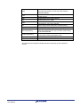
8. The quality grade of each Renesas Electronics product is “Standard” unless otherwise expressly
specified in a Renesas Electronics data sheets or data books, etc.
“Standard”:
Computers; office equipment; communications equipment; test and measurement
equipment; audio and visual equipment; home electronic appliances; machine
tools; personal electronic equipment; and industrial robots.
“High Quality”: Transportation equipment (automobiles, trains, ships, etc.); traffic control
systems; anti-disaster systems; anti- crime systems; safety equipment; and
medical equipment not specifically designed for life support.
“Specific”:
Aircraft; aerospace equipment; submersible repeaters; nuclear reactor control
systems; medical equipment or systems for life support (e.g. artificial life support
devices or systems), surgical implantations, or healthcare intervention (e.g.
excision, etc.), and any other applications or purposes that pose a direct threat to
human life.
9. You should use the Renesas Electronics products described in this document within the range
specified by Renesas Electronics, especially with respect to the maximum rating, operating
supply voltage range, movement power voltage range, heat radiation characteristics, installation
and other product characteristics. Renesas Electronics shall have no liability for malfunctions or
damages arising out of the use of Renesas Electronics products beyond such specified ranges.
10. Although Renesas Electronics endeavors to improve the quality and reliability of its products,
semiconductor products have specific characteristics such as the occurrence of failure at a
certain rate and malfunctions under certain use conditions. Further, Renesas Electronics products
are not subject to radiation resistance design. Please be sure to implement safety measures to
guard them against the possibility of physical injury, and injury or damage caused by fire in the
event of the failure of a Renesas Electronics product, such as safety design for hardware and
software including but not limited to redundancy, fire control and malfunction prevention,
appropriate treatment for aging degradation or any other appropriate measures. Because the
evaluation of microcomputer software alone is very difficult, please evaluate the safety of the final
products or system manufactured by you.
11. Please contact a Renesas Electronics sales office for details as to environmental matters such as
the environmental compatibility of each Renesas Electronics product. Please use Renesas
Electronics products in compliance with all applicable laws and regulations that regulate the
inclusion or use of controlled substances, including without limitation, the EU RoHS Directive.
Renesas Electronics assumes no liability for damages or losses occurring as a result of your
noncompliance with applicable laws and regulations.
12. This document may not be reproduced or duplicated, in any form, in whole or in part, without prior
written consent of Renesas Electronics.
13. Please contact a Renesas Electronics sales office if you have any questions regarding the
information contained in this document or Renesas Electronics products, or if you have any other
inquiries.
(Note 1) “Renesas Electronics” as used in this document means Renesas Electronics
Corporation and also includes its majority- owned subsidiaries.
(Note 2) “Renesas Electronics product(s)” means any product developed or manufactured
by or for Renesas Electronics.
R01US0046ED Rev. 1.01
User Manual
3
Regional Information
Some information contained in this document may vary from country to country. Before using any
Renesas Electronics product in your application, please contact the Renesas Electronics office in your
country to obtain a list of authorized representatives and distributors. They will verify:
• Device availability
• Ordering information
• Product release schedule
• Availability of related technical literature
• Development environment specifications (for example, specifications for
third-party tools and components, host computers, power plugs, AC supply
voltages, and so forth)
• Network requirements
In addition, trademarks, registered trademarks, export restrictions, and other legal issues may also vary
from country to country.
Visit
http://www.renesas.com
to get in contact with your regional representatives and distributors.
R01US0046ED Rev. 1.01
User Manual
4
Preface
Readers This manual is intended for users who want to understand the functions of the
concerned libraries.
Purpose This manual presents the software manual for the concerned libraries.
Organization This document describes the following sections:
Architecture
Implementation and Usage
API
Note Additional remark or tip
Caution Item deserving extra attention
Numeric notation Binary:
xxxx or xxxB
Decimal:
xxxx
Hexadecimal
xxxxH or 0x xxxx
Numeric prefixes Representing powers of 2 (address space, memory capacity):
10
K (kilo): 2 = 1024
20
M (mega):
2 = 1024² = 1,048,576
G (giga):
2 = 1024³ = 1,073,741,824
30
Register contents X, x = don’t care
Diagrams Block diagrams do not necessarily show the exact software flow but the
functional structure. Timing diagrams are for functional explanation purposes only,
without any relevance to the real hardware implementation.
R01US0046ED Rev. 1.01
User Manual
5
How to Use This Manual
(1)
Purpose and Target Readers
This manual is designed to provide the user with an understanding of the library
itself and the functionality provided by the library. It is intended for users
designing applications using libraries provided by Renesas. A basic knowledge of
software systems as well as Renesas microcontrollers is necessary in order to
use this manual. The manual comprises an overview of the library, its
functionality and its structure, how to use it and restrictions in using the library.
Particular attention should be paid to the precautionary notes when using the
manual. These notes occur within the body of the text, at the end of each section,
and in the Usage Notes section.
The revision history summarizes the locations of revisions and additions. It does
not list all revisions. Refer to the text of the manual for details.
(2)
List of Abbreviations and Acronyms
Abbreviation
Full Form
API
Application Programming Interface
Boot Cluster
A number of flash blocks is combined to a cluster (used
for swapping and protection) located at reset address
Bootloader
A piece of software located in the Boot Cluster handling
the reprogramming of the device
Code Flash
Embedded Flash where the application code or constant
data is stored.
Dual Operation
Dual operation is the capability to access flash memory
during reprogramming another flash memory range.
Dual operation is available between Code Flash and
Data Flash.
Between different Code Flash macros dual operation
depends on the device implementation
ECC
Error Correction Code
Firmware
Firmware is a piece of software that is located in a
hidden area of the device, handling the interfacing to the
flash.
Flash
Electrically erasable and programmable nonvolatile
memory. Different to ROM this type of memory can be
re-programmed several times.
Flash Area
Area of Flash consists of several coherent Flash Blocks
Flash Block
A flash block is the smallest erasable unit of the flash
memory.
Flash Macro
A certain number of Flash blocks are grouped together in
a Flash macro.
FSL
Flash Self-Programming Library
FSS
Flash Self-Programming System
FSW
Flash Shield Window
FW
Firmware
R01US0046ED Rev. 1.01
User Manual
6
NVM
Non volatile memory. All memories that hold the value,
even when the power is cut off. E.g. Flash memory,
EEPROM, MRAM...
RAM
“Random access memory” - volatile memory with
random access
REE
Renesas Electronics Europe GmbH
REL
Renesas Electronics Japan
ROM
“Read only memory” - nonvolatile memory. The content
of that memory can not be changed.
SCI
Status check internal mode (See "Internal mode")
SCU
Status check user mode (See "User mode")
Self-Programming
Capability to reprogram the embedded flash without
external programming tool only via control code running
on the microcontroller.
Serial programming
The onboard programming mode is used to program the
device with an external programmer tool.
SPL
See "Self-Programming Library"
All trademarks and registered trademarks are the property of their respective
owners.
R01US0046ED Rev. 1.01
User Manual
7
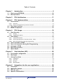
Table of Contents
Chapter 1
1.1
1.2
Introduction ......................................................................... 9
Flash versus EEPROM .................................................................................. 10
Dual Operation ............................................................................................... 10
Chapter 2
FSL Architecture................................................................ 11
Chapter 3
FSL Implementation .......................................................... 12
3.1
File structure .................................................................................................. 12
3.1.1
3.1.2
3.2
3.3
FSL Linker sections ...................................................................................... 15
MISRA Compliance ........................................................................................ 15
Chapter 4
4.1
User Interface (API) ........................................................... 25
Pre-compile configuration ............................................................................ 25
Data Types ..................................................................................................... 26
Library Functions .......................................................................................... 27
5.3.1
5.3.2
5.3.3
5.3.4
Chapter 6
6.1
6.2
6.3
6.4
Hardware Protection ..........................................................................................................19
Normal operation (Error Correction Circuit – ECC) ...........................................................19
Safe reprogramming using Self-Programming ..................................................................19
Code execution in RAM ................................................................................ 21
User code execution during Self-Programming ......................................... 22
Interrupts in RAM .......................................................................................... 23
Dual CPU operation ....................................................................................... 24
Option Bytes .................................................................................................. 24
Chapter 5
5.1
5.2
5.3
Strategy .............................................................................................................................16
Configuration options .........................................................................................................17
Flash Safety ................................................................................................... 18
4.2.1
4.2.2
4.2.3
4.3
4.4
4.5
4.6
4.7
FSL Usage .......................................................................... 16
Flash Security ................................................................................................ 16
4.1.1
4.1.2
4.2
Overview ............................................................................................................................12
Delivery package directory structure and files ...................................................................13
Initialization ........................................................................................................................28
Operation ...........................................................................................................................33
Security ..............................................................................................................................37
Administration ....................................................................................................................45
Integration into the user application ................................ 59
First steps ...................................................................................................... 59
Application sample ........................................................................................ 59
FSL life cycle.................................................................................................. 59
Special considerations ................................................................................. 61
R01US0046ED Rev. 1.01
User Manual
8
Flash Self-Programming Library
Introduction
Chapter 1 Introduction
This user’s manual describes the internal structure, the functionality and software
interface (API) of the Renesas V850 Flash Self-Programming Library (FSL) type
T06. The library type T06 is suitable for all Renesas V850 Flash based on the
RC03F Flash technology.
Caution Do not use this library for devices based on other Flash technologies than RC03F,
as this might lead to unwanted behaviour or demolition of the device.
The device features differ depending on the used Flash implementation and
basic technology node. Therefore, pre-compile and run-time configuration options
allow adaptation of the library to the device features and to the application needs.
The libraries are delivered in source code. However it has to be considered
carefully to do any changes, as not intended behaviour and programming faults
might be the result.
The development environments of the companies Green Hills (GHS), IAR and
Renesas are supported. Due to the different compiler and assembler features,
especially the assembler files differ between the environments. So, the library
and application programs are distributed using an installer tool allowing selecting
the appropriate environment.
For support of other development environments, additional development effort
may be necessary. Especially, but maybe not only, the calling conventions to the
assembler code and compiler dependent section defines differ significantly.
The libraries are delivered together with device dependent application programs,
showing the implementation of the libraries and the usage of the library functions.
The different options of setup and usage of the libraries are explained in detail in
this document.
Caution Please read all chapters of the application note carefully.
Much attention has been put to proper conditions and limitations description.
Anyhow, it can never be ensured completely that all not allowed concepts of
library implementation into the user application are explicitly forbidden. So,
please follow exactly the given sequences and recommendations in this
document in order to make full use of the libraries functionality and features and
in order to avoid any possible problems caused by libraries misuse.
The Flash Self-Programming Libraries together with application samples, this
manual and other device dependent information can be downloaded from the
following URL:
http://www.renesas.eu/update
R01US0046ED Rev. 1.01
User Manual
9
Flash Self-Programming Library
Introduction
1.1 Flash versus EEPROM
2
Major difference between Flash and EEPROM (or E PROM) is the
reprogramming granularity. EEPROM can be reprogrammed wordwise, where
the size of one word depends on the organization and interface. It can vary in the
wide range between 8 bit and 256 bytes.
Depending on the implementation, Flash may also be programmed wordwise, but
the Erase can only be done on a complete block. This is the major limitation of
Flash against EEPROM, but due to that the memory hardware effort can be
reduced significantly, making the embedded non volatile memory for program
code affordable.
1.2 Dual Operation
Common for all Flash implementations is, that during Flash modification
operations (Erase/Write) a certain amount of Flash memory is not accessible for
any read operation (e.g. program execution or data read).
This does not only concern the modified Flash range, but a certain part of the
complete Flash system. The amount of not accessible Flash depends on the
device architecture.
A standard architectural approach is the separation of the Flash into Code Flash
and Data Flash. By that, it is possible to read from the Code Flash (to execute
program code or read data) while Data Flash is modified, and vice versa.
To check whether Dual Operation is supported by a device, please refer to the
device user manual.
Note It is not possible to modify Code Flash and Data Flash in parallel
R01US0046ED Rev. 1.01
User Manual
10
Flash Self-Programming Library
FSL Architecture
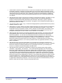
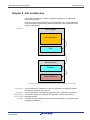
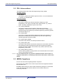
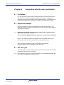
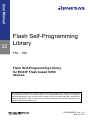
Chapter 2 FSL Architecture
This chapter describes the function of all blocks belonging to the Flash SelfProgramming System.
Even though this manual describes the functional block FSL, a short description
of all concerned functional blocks and their relationship can be beneficial for the
general understanding.
Figure 2-1
User Program
User Application
FSL
Microcomputer
Firmware
Flash Hardware
Rough relationship between functional system blocks of the FSS
Application The functional block “Application” is the user application (including a potential
bootloader) provided by the customer.
Flash Self- The functional block “Flash Self-Programming Library” offers all functions and
Programming commands necessary to reprogram the application using a user friendly C
Library (FSL) language interface.
Firmware The block firmware provides the device internal functionality to control the Flash
programming hardware.
R01US0046ED Rev. 1.01
User Manual
11
Flash Self-Programming Library
FSL Implementation
Chapter 3 FSL Implementation
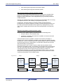
3.1 File structure
The library is delivered as a complete compilable sample project which contains
the FSL and in addition an application sample to show the library implementation
and usage in the target application.
The application sample initializes the FSL and does some dummy data set Erase
and Write operations.
Differing from former Self-Programming Libraries, this one is realized not as an
IDE related specific sample project, but as a standard sample project which is
controlled by makefiles.
Following that, the sample project can be built in a command line interface and
the resulting elf file can be run in the debugger.
The delivery package contains dedicated directories for the library containing the
source and the header files.
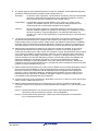
3.1.1
Overview
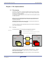
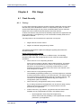
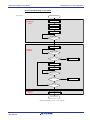
The following picture contains the library and application related files:
Figure 3-1
Library Files – Fix, may not be touched by the user
Library pre-compile configuration – File name fix, File content user configurable
Application (User) Code – Completely in the hand of the user
API declaration
Libray
User
Source Code
Application
FSL.h
Source Code
Library
EEL_...c
EEL_...c
FSL_Cfg.h
EEL_...c
EEL_...c
App....c
FSL_...c
Library
Configuration
Library and application file structure
The library code consists of different source files, starting with FSL_... The files
shall not be touched by the user, independently, if the library is distributed as
source code or pre-compiled.
The file FSL.h is the library interface functions header file. It also includes library
interface parameters and types.
R01US0046ED Rev. 1.01
User Manual
12
Flash Self-Programming Library
FSL Implementation
In case of source code delivery, the library must be configured for compilation.
The file FSL_Cfg.h contains defines for that. As it is included by the library source
files, the file contents may be modified by the user, but the file name may not.
Caution Wrong configuration of the FSL might lead to undefined results.
FSL_User.c and FSL_User.h do not belong to the libraries themselves, but to the
user application. These files reflect an example, how to activate the Flash
environment and handle the FLMD0 pin.
If overtaking the files FSL_User.c/h into the user application, only the file
FSL_User.c need to be adapted by the user, while FSL_User.h may remain
unchanged.
3.1.2
Delivery package directory structure and files
The following table contains all files installed by the library installer.
Files in red belong to the build environment, controlling the compile, link and
target build process
Files in blue belong to the sample application
Files in green are description files only
Files in black belong to the FSL
[root]
Release.txt
Installer package release notes
[root]\[make]
GNUPublicLicense.txt
Make utility license file
libiconv2.dll
DLL-File required by make.exe
libintl3.dll
DLL-File required by make.exe
make.exe
Make utility
[root]\[<device name>]\[compiler]
Build.bat
Batch file to build the application sample
Clean.bat
Batch file to clean the application sample
Makefile
Makefile that controls the build and clean
process
R01US0046ED Rev. 1.01
User Manual
13
Flash Self-Programming Library
FSL Implementation
[root]\ [<device name>]\[<compiler>]\[sample]
Main.c
Main source code
target device and application related
definitions
target.h
df<device number>.h
GHS
df<device number>_irq.h
io_macros_v2.h
device header files
io_70f< device number>.h
IAR
io_macros.h
lxx.h
startup file
linker directive file
GHS
cfi.h
IAR
l07.s85
REC
cstartup.s85
GHS
df<dev. num.>.ld
IAR
lnk70f<dev. num.>.xcl
REC
df<dev. num.>.dir
[root]\ [<device name>]\[<compiler>]\[sample] \[FSL]
Header file with definitions for library setup at
FSL_cfg.h
compile time
linker directive file
Header file containing function prototypes,
error and status codes
FSL_User.h
User file header including Flash environment
activation / deactivation and FLMD0 handling.
To be edited by the user.
startup file
User file including Flash environment
activation / deactivation and FLMD0 handling.
Maybe modified by the user.
[root]\ [<device name>]\[<compiler>]\[sample] \[FSL] \[lib]
Library internal defines, function prototypes
FSL_Global.h
and variables
FSL_UserIF_Init.c
Source code for the FSL initialization
linker directive file
Source code for the normal FSL operations
FSL_FirmwareIF.c
Interface to the firmware
FSL_BasicFct.c
Source code of basic functions used during
Self-Programming
GHS
FSL_BasicFct_Asm.850
IAR
FSL_BasicFct_Asm.s85
REC
FSL_BasicFct_Asm.asm
R01US0046ED Rev. 1.01
User Manual
Assembler code of basic functions used
during Self-Programming
14
Flash Self-Programming Library
FSL Implementation
3.2 FSL Linker sections
The following sections are Flash Self-Programming Library related.
FSL data sections
FSL_DATA
This section contains the variables required for FSL. It can be located either
in internal or in external RAM.
FSL code sections
FSL_CODE_ROM
This section contains the code executed at the beginning of SelfProgramming. This code is executed at the original location, e.g. internal
Flash. The library initialization is part of this section.
FSL_CODE_ROMRAM
The section contains the user interface. Depending on the library
configuration, code from this section has to be executed in a Memory area
outside the Flash area affected by the Self-Programming operation (typically
executed in RAM) or not.
FSL_CODE_RAM
This section contains the firmware interface and has to be executed in a
Memory area outside the Flash area affected by the Self-Programming
operation (typically executed in RAM).
FSL_CODE_RAM_USRINT
This section may contain user interrupt handler functions.
FSL_CODE_RAM_USR
This section may contain user functions and has to be executed in a Memory
area outside the Flash area affected by the Self-Programming operation
(typically executed in RAM). User functions may contain code for the SelfProgramming control flow.
FSL_CODE_RAM_EX_PROT
This is a dummy section to avoid prefetch errors at the borders of the copied
sections during RAM execution.
Caution It is not allowed to place any section in between the FSL code sections. A
violation of that rule or a reordering of the sections will cause a crash of the
library.
3.3 MISRA Compliance
The FSL has been tested regarding MISRA compliance.
The used tool is the QAC Source Code Analyzer which tests against the MISRA
2004 standard rules.
All MISRA related rules have been enabled. Remaining findings are commented
in the code while the QAC checker machine is set to silent mode in the
concerning code lines.
R01US0046ED Rev. 1.01
User Manual
15
Flash Self-Programming Library
FSL Usage
Chapter 4
FSL Usage
4.1 Flash Security
4.1.1
Strategy
In most cases application software contains important intellectual property and/or
data that may not be distributed to others or manipulated by others. In order to
ensure Flash data integrity and to prevent unintended data read-out, Renesas
implements a set of features and mechanisms into Flash devices.
As these mechanisms may also limit the flexibility required for the application and
the programming or reprogramming, it has to be decided carefully what level of
protection is intended.
Two major items to be considered in the protection concept are:
Illegal read-out of Flash content
Illegal or accidental reprogramming of Flash
The following descriptions explain the strategies regarding these items are
described in detail:
Illegal read-out of Flash content
Read-out, legal and illegal, can be done on different ways. The following
describes major ways and the appropriate counter measures against illegal
operations:
Direct read-out via on-chip debug interface
Some devices contain the N-Wire / Nexus debug interface. This allows
full control over all data stored in the device. It can be protected by a
password. As the protection is not directly a Flash feature, it is just
mentioned for reference. Please refer to the device user manual or the
tools description for details.
Direct read-out via programming interface
The standard programming interface (e.g. PG-FP5) supports a command
to read out the Flash contents on all current devices. This feature helps a
lot in the developing and debugging phase and for failure analysis. This
command can be disabled by a protection flag (see chapter 4.1.2
Configuration options for details)
Direct read-out by the application itself (via any interface)
E.g. a debug command in the application can be used to dump memory.
Please ensure that this possibility is not implemented or at least
protected in your application.
Indirect read-out by spy software, programmed into the internal Flash
Software can be programmed into Flash in two different ways:
o
By the application itself using Self-Programming
Please ensure that this possibility is not implemented or at least
protected in your application.
R01US0046ED Rev. 1.01
User Manual
16
Flash Self-Programming Library
FSL Usage
o
By the programmer interface
In order to disable this feature, the commands Flash Write and
Flash Block Erase can be disabled (see chapter 4.1.2
Configuration options for details). By doing so, Flash writing via
this interface is only possible after erasing the complete Flash.
Illegal or accidental reprogramming of Flash
For many applications protection against the illegal Flash read-out is already
sufficient. In other cases reprogramming the device either completely or partly
must be disabled. V850 devices provide features for both:
Partly reprogramming by the programmer interface
See Illegal read-out of Flash content
Complete reprogramming by the programmer interface
If also the complete erasing and reprogramming by this interface shall be
disabled, in addition to Flash Write and Flash Block Erase commands
also the Chip Erase command can be disabled (see chapter 4.1.2
Configuration options for details). By doing so the reprogramming via
programmer interface is no longer possible, neither by unauthorized nor
by authorized use. Reprogramming by the application using SelfProgramming is still possible.
Reprogramming by the application using Self-Programming
It is also possible to protect a certain number of Flash blocks (called boot
cluster) against reprogramming via the application, starting from
0x00000000. The number of blocks is configurable from 1 up to the
complete Flash.
So it is possible to protect e.g. a Bootloader or more code and data up to
the complete application.
In addition a configurable Flash Shield Window is able to protect parts of
the Flash. This Window is configurable via Self-Programming. Only the
Flash blocks covered by the FSW can be reprogrammed via SelfProgramming.
Note When disabling reprogramming of blocks via the application, the secured part can
no longer be reprogrammed in any way any more.
4.1.2
Configuration options
This chapter explains the protection relevant settings and mechanisms,
implemented in RC03F based Flash devices.
For the usage of these settings and the protection strategy, please refer to
section 4.1.1 Strategy.
(1)
Security Flags
The protection configuration can be set by the dedicated Flash programmers, like
PG-FP5 or via Self-Programming.
The following flags and settings are available:
Read command disable (Programmer interface)
Reading the Flash contents via the programming interface is disabled. It
does not affect Self-Programming (see FSL_SetReadProtectFlag).
R01US0046ED Rev. 1.01
User Manual
17
Flash Self-Programming Library
FSL Usage
Program command disable (Programmer interface)
Writing to the Flash via programming interface is disabled. It does not
affect Self-Programming (see FSL_SetWriteProtectFlag).
Block Erase command disable (Programmer interface)
Erasing single blocks via programming interface is disabled. It does not
affect Self-Programming. The Flag is valid for the complete Flash (see
FSL_SetBlockEraseProtectFlag).
Boot Cluster Protection
If set, erasing and writing on the Flash by the application using the SelfProgramming is disabled for the boot cluster (see
FSL_SetBootClusterProtectFlag).
Caution If set once, resetting is only possible for the read and write protection flag.
(2)
ID Code Protection
Flash access via N-Wire / Nexus debug interface can be secured via an internal
ID. The ID is stored in the Extra Area and has to match the configure ID in the NWire interface configuration of the debugger to allow Flash access. For details
about the ID, please refer to FSL_SetID.
(3)
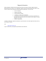
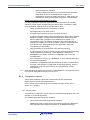
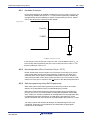
Flash Shield Window
Internal Flash can be protected from accidental reprogramming by a shield
window. This window is configurable during runtime. It allows to program or to
erase all Flash blocks covered by the window and denies destructive access to
all other blocks. Per default all Flash blocks are covered by the Flash Shield
Window. For details how to configure the Flash Shield Window, please refer to
FSL_SetFSW.
Figure 4-1
protected area
unprotected area
protected area
shield window
0x0000 0000
0x0040 0000
Flash Shield Window
4.2 Flash Safety
All RC03F based Flash devices are equipped with dedicated safety features. The
features have to be separated for normal operation, where data retention is
important and for reprogramming, where safe reprogramming in case of power
fail or other problems is important.
R01US0046ED Rev. 1.01
User Manual
18
Flash Self-Programming Library
4.2.1
FSL Usage
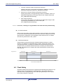
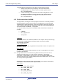
Hardware Protection
Device Reprogramming is disabled if FLMD0 Pin is low. By using a port pin or an
external logic FLMD0 must be set to “1” to allow Self-Programming. Additionally
reprogramming can be enabled by a register if supported by the device. Please
refer to the device user manual for further details.
Figure 4-2
Port-Pin
FLMD0
R
Vss
FLMD0 sample circuit
In the sample circuit, the port pin is input on reset. Thus FLMD0 is held to VSS on
reset. During Self-Programming the port is set to output and to the value “1”. By
that the FLMD0 pin is set to VDD.
4.2.2
Normal operation (Error Correction Circuit – ECC)
RC03F based Flash devices contain Error Correction Circuits (ECC) to provide
correct Flash data. During Flash write operations, beside the user data, also
redundant ECC data is written into additional Flash cells in order to be able to
correct detected Flash errors during Flash read. ECC is an on-line method. That
means from user point of view ECC has no impact on the data read performance.
4.2.3
Safe reprogramming using Self-Programming
When talking about safe Self-Programming, that naming needs to be exactly
defined, as several different ways of understanding are possible.
Basic idea of safe Self-Programming is that if anything during reprogramming
process goes wrong, it must be possible to keep basic application functionality
alive. Usually it is solved by separation of the application into the application that
is updated and therefore temporarily not valid during reprogramming, and a
specific bootloader that must always be executable again after power up or reset.
Two major options with different advantages and disadvantages have to be
considered. Depending on the application and bootloader the appropriate
solution has to be selected:
R01US0046ED Rev. 1.01
User Manual
19
Flash Self-Programming Library
FSL Usage
Safe Self-Programming without bootloader update
Safe Self-Programming with bootloader update
Safe Self-Programming without bootloader update
The easiest way of safe Self-Programming is to occupy some complete Flash
blocks for the bootloader and do not reprogram them again. By that it never
happens, that an interruption of the reprogramming (e.g. power fail) causes an
invalid bootloader.
Although this method might waste some space if the bootloader does not occupy
a complete Flash block, the handling of reprogramming is easy.
Furthermore, increased safety by protection against reprogramming the
bootloader due to program failures is possible. The block protection feature can
be used to protect the bootloader forever against any reprogramming. In that
case, please consider that the block cannot be reprogrammed in any way any
more.
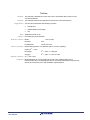
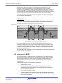
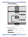
Safe Self-Programming with bootloader update
Bootloader block update might be necessary due to the following items:
Keep the option to fix bootloader bugs.
Application code/data, that needs to be updated, is stored in the same
block as the bootloader.
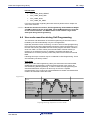
If the bootloader has to be updated, it needs to be ensured, that always a
working version of the bootloader is available, even during the update procedure.
Furthermore, in case of a power failure the valid bootloader needs to be detected
and the program has to be started there. To fulfil these requirements, the Boot
Swap functionality is implemented.
Boot swap means, that a certain number of Flash blocks (clusters) can be
swapped in the address range. This swapping is done depending on Boot Swap
bits, set in the Flash Extra Areas. When a valid bootloader is contained in the
corresponding cluster and the swap bit is set accordingly, the block is
automatically swapped to the address 0x00000000 on device start-up. By that
and by the correct reprogramming sequence can be ensured, that even a block
containing a bootloader can be updated safely.
Figure 4-3
Step 1:
Old
User application
(valid)
Old bootloader
(boot cluster 0)
Unswapped
Step 2:
Step 3:
Old
User application
(invalid)
Old
User application
(invalid)
New bootloader
(boot cluster 1)
Old bootloader
(boot cluster 0)
Old bootloader
(boot cluster 0)
New bootloader
(boot cluster 1)
Swap
New
User application
(valid)
New bootloader
(boot cluster 1)
Swapped
Safe bootloader update
R01US0046ED Rev. 1.01
User Manual
20
Flash Self-Programming Library
FSL Usage
Two methods are implemented in the Library to swap the boot cluster.
1. Swap the boot cluster only temporary. The boot cluster will be
unswapped again after a device reset. For details, please refer to
FSL_ChangeSwapState.
2. Invert the boot flag. The boot cluster will remain changed after a reset.
An additional parameter forces the device to swap the boot cluster
immediately in addition to changing the swap flag. Please refer to
FSL_ChangeSwapFlag.
4.3 Code execution in RAM
The application, including the control program and the FSL are usually located in
the internal flash. As the memory location of the application is not permanently
available during Self-Programming, parts of the program need to be copied to a
“save” location, where they can be executed. This may be the internal RAM, but
also external RAM, if available, is acceptable.
To copy necessary code parts into available RAM, three different methods are
possible:
C-Startup
FSL_CopySections
User specific
C-Startup
The code is linked to the destination address. The compiler start-up routines copy
the code from a ROM image to the RAM. Please refer to the compiler
documentation for details.
FSL_CopySections
By calling the function FSL_CopySections all specified sections are copied to the
destination address.
User specific
In case of a user specific implementation, the user is responsible for the correct
location of the sections.
Note During RAM execution as well as during ROM execution, the device tries to
speed up execution time by a code prefetch mechanism. This prefetch
mechanism is responsible for ECC errors in case of uninitialized RAM areas.
Therefore the user has to initialize 32 Bytes behind the RAM placed code in case
of a user specific implementation.
Depending on the configured mode (see section 5.1 Pre-compile configuration)
following linker sections need to be copied to RAM:
User mode
R01US0046ED Rev. 1.01
User Manual
FSL_CODE_RAM_USRINT
FSL_CODE_RAM_USR
FSL_CODE_RAM
FSL_CODE_ROMRAM
FSL_CODE_EX_PROT
21
Flash Self-Programming Library
FSL Usage
Internal mode
FSL_CODE_RAM_USRINT
FSL_CODE_RAM_USR
FSL_CODE_RAM
FSL_CODE_EX_PROT
For further information regarding the linker sections please refer to chapter 3.2
“FSL Linker sections”
Caution Beside the mentioned sections, Self-Programming needs additional 4kByte
of RAM located on the top of the RAM. These RAM addresses are reserved
for the internal firmware. The RAM content in this address range will be
destroyed during Self-Programming.
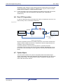
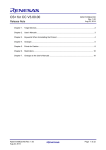
4.4 User code execution during Self-Programming
The activation and deactivation of the Self-Programming Environment can be
handled by the FSL automatically or by the user application.
Especially activation is time consuming. In order to achieve fast reprogramming
the environment should be kept activated during the whole reprogramming. On
the other hand, during activated environment the program execution cannot be
done from Flash. So other memory like internal RAM or external memory is
required. If not sufficient memory is available, sequential activation and
deactivation is necessary and only small code parts are executed from internal
RAM.
Following two major scenarios may be considered for Self-Programming. These
are reflected by the library modes:
User mode
Most parts of the Self-Programming Library are executed in the internal RAM,
additionally the reprogramming control functions and other user code to be
executed during Self-Programming. In order to realise fast reprogramming the
activation/deactivation sequence is done only once for the complete
reprogramming. Every code to be executed between activation and deactivation
needs to be executed outside the Flash.
Figure 4-4
Firmware
Firmware Interface
FSL User Interface
...
Execution
in RAM
FSL_FlashEnv_Activate /
FSL_FlashEnv_Deactivate
User Control Program
Execution
in Flash
User Application
No Flash access possible
Reprogramming sequence in user mode
R01US0046ED Rev. 1.01
User Manual
22
Flash Self-Programming Library
FSL Usage
This sequence is best for devices with sufficient internal RAM. User code
execution is always possible during Self-Programming, because a Flash
operation is just initiated by the FSL command. While the FSL returns control to
the user application, the Flash operation is executed in background. The user
has to poll the command status via the status check function. Interrupt as well as
user code execution is possible if all related functions are located in RAM.
To enable this mode, the library must be configured to use the user mode (see
5.1 Pre-compile configuration).
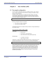
Internal mode
Only small parts of the library are executed in RAM, the rest is executed in the
Code Flash. Frequent activation and deactivation of the Flash Environment is
necessary and therefore programming time will increase.
Figure 4-5
Firmware
Execution
in RAM
Firmware Interface
FSL User Interface
...
User Control Program
Execution
in Flash
User Application
No Flash
Access
possible
No Flash
Access
possible
Basic RAM saving reprogramming sequence
Less internal RAM is used as only the device firmware interface need to be
executed in RAM. On the other hand, normal user code execution during SelfProgramming is impossible, because a FSL function starting a command does
not return until the operation is finished. Therefore only interrupts are possible
during Self-Programming.
To enable this mode, the library must be configured to use the internal mode (see
5.1 Pre-compile configuration).
4.5 Interrupts in RAM
As mentioned before, Code Flash is not accessible during Self-Programming.
Therefore the interrupt vector table as well as interrupt handler routines, which
are normally located in the Flash, are not accessible. Interrupt vectors and
handler routines have to be re-routed to not affected memory like external or
internal RAM.
Two methods exist to execute interrupts from RAM:
Single interrupt vector
All interrupts are mapped to the single interrupt vector of interrupt
channel 0. Based on this interrupt, the interrupt handler routine has to
handle all pending interrupts.
Interrupt table mapped to RAM
The base address of the interrupt vector table is mapped to a different
location in RAM. In this case the offset of the different channels is added
to the new base address.
R01US0046ED Rev. 1.01
User Manual
23
Flash Self-Programming Library
FSL Usage
Regardless which method is used, interrupt service routines have to be executed
from and therefore copied to RAM. For details how to copy the routines to RAM,
please refer to chapter 4.3 “Code execution in RAM”.
Note Further information about interrupt handling from RAM can be found in the device
user manual and in the CPU architecture description (see “V850E2R-V3
Architecture”).
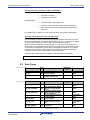
4.6 Dual CPU operation
In case of a dual CPU device the usage of the FSL is not limited to one CPU. The
Flash memory can be controlled by each CPU.
Figure 4-6
Flash Memory
Data access bus
(high speed)
Service functions
CPU1
CPU2
RAM
RAM
CPU-CPU memory access
bus
(low speed)
Dual CPU operation
Dual CPU operation causes some smaller restrictions. The service functions are
always located in RAM area of CPU1. Therefore the function response time will
increase in case of control by CPU2.
A second restriction is access control in general. To provide a fail safe
mechanism, only access by one CPU at a time is allowed. Simultaneous access
by the other CPU is prohibited. Access rights are controlled automatically by the
library.
4.7 Option Bytes
The Extra Area contains user specific configuration data called Option Bytes.
These configuration settings are adjustable via Self-Programming. The size of the
Option Bytes is 4Byte. For details about possible configuration settings please
refer to the device user manual.
R01US0046ED Rev. 1.01
User Manual
24
Flash Self-Programming Library
Chapter 5
User Interface (API)
User Interface (API)
5.1 Pre-compile configuration
The pre-compile configuration of the FSL is located in the FSL_cfg.h. The user
has to configure all parameters and attributes by adapting the related constant
definition in that header-file.
This file may also contain device or application specific defines. The define
FSL_STATUS_CHECK needs to be configured. It defines whether the status
check should be performed by the firmware or by the user to allow execution of
user code in between the status checks.
#define FSL_STATUS_CHECK
FSL_STATUS_CHECK_INTERNAL
Following configuration options are possible:
FSL_STATUS_CHECK_INTERNAL
FSL_STATUS_CHECK_USER
As described in the previous chapter the library behaviour changes depending on
the configure mode.
User mode (FSL_STATUS_CHECK_USER)
Advantages:
less CPU time
less activation / deactivation time
user code execution during Self-Programming
more RAM consumption
status polling necessary
Disadvantages:
Additionally, in status check user mode, user can enable or disable polling in the
activation and deactivation functions of the library by setting following define:
#define FSL_ACTIVATION_POLLING
If the activation polling is disabled, the function will automatically return after the
activation operation is finished. The activation / deactivation process needs
longer execution time than any other operation. As this operation is normally
executed once at the beginning, the longer execution time is acceptable. By
setting the pre-processor define, the process is split up and the execution is
controlled by the status check like normal Flash operations. So the function
execution time is reduced.
R01US0046ED Rev. 1.01
User Manual
25
Flash Self-Programming Library
User Interface (API)
Internal mode (FSL_STATUS_CHECK_INTERNAL)
Advantages:
no polling necessary
less RAM consumption
more activation / deactivation time
no return to the application during Self-Programming
user code execution during Self-Programming only by
interrupts
Disadvantages:
For details refer to chapter 4.4 User code execution during Self-Programming.
Synchronization between Code and Data Flash
It is not possible to access Code Flash during Data Flash access and vice versa
due to similar hardware and limited internal resources, e.g. a single charge pump.
To protect and synchronize Code Flash and Data Flash accesses a
synchronization mechanism is implemented. This mechanism will postpone all
Code Flash access if a Data Flash access is ongoing until the Data Flash access
is terminated. A Data Flash access during Code Flash accesses is very unlikely,
because code execution is only possible from RAM during Self-Programming.
Therefore the access from Data Flash is not synchronized.
To enable the synchronization mechanism, following define is necessary:
#define FSL_CODE_DATA_FLASH_SYNC_ENABLED
5.2 Data Types
Figure 5-1
Error
Valu
e
Explanation
Responsible
process
FSL Impact
FSL_OK
0x00
The operation finished successfully
Correct result
FSL_IDLE
0x30
No operation is ongoing
A new function call is
possible
FSL_BUSY
0xFF
The operation has been started
successfully and is still running.
Correct result
FSL status codes
Figure 5-2
Error
Value
Explanation
Responsible
process
FSL Impact
FSL_ERR_FLMD0
0x01
The FLMD0-Pin is not at a High level.
Current command
rejected
FSL_ERR_PARAMETER
0x05
A new operation should be initiated,
but an error in the given parameter
occurred.
Current command
rejected
FSL_ERR_PROTECTION
0x10
A new operation should be initiated
although this operation is forbidden
due to a security feature.
Current command
rejected
FSL_ERR_ERASE
0x1A
The current operation stopped due to
an error while erasing.
Current command
aborted.
FSL_ERR_WRITE
0x1C
The current operation stopped due to
an error while writing.
Current command
aborted.
FSL_ERR_FLOW
0x1F
A new operation should be initiated
although the state machine is still
busy.
Current command
rejected
FSL_ERR_INTERNAL
0xAA
The current operation stopped due to
an internal error.
Current command
aborted.
FSL error codes
R01US0046ED Rev. 1.01
User Manual
26
Flash Self-Programming Library
User Interface (API)
5.3 Library Functions
Functions represent the application interface to the FSL which the user SW can
use. Following list is an overview of all available functions (in alphabetic order).
R01US0046ED Rev. 1.01
User Manual
FSL_CalcFctAddr
FSL_ChangeSwapFlag
FSL_ChangeSwapState
FSL_CopySections
FSL_Erase
FSL_FlashEnv_Activate
FSL_FlashEnv_Deactivate
FSL_GetBlockCnt
FSL_GetBlockEndAdd
FSL_GetBootClusterSize
FSL_GetDevice
FSL_GetFSW
FSL_GetID
FSL_GetOPB
FSL_GetSecurityFlags
FSL_GetSwapFlag
FSL_GetSwapState
FSL_GetVersionString
FSL_Init
FSL_ModeCheck
FSL_Read
FSL_SetBlockEraseProtectFlag
FSL_SetBootClusterProtectFlag
FSL_SetBootClusterSize
FSL_SetFrequency
FSL_SetFSW
FSL_SetID
FSL_SetOPB
FSL_SetReadProtectFlag
FSL_SetWriteProtectFlag
FSL_StatusCheck
FSL_Write
27
Flash Self-Programming Library
5.3.1
User Interface (API)
Initialization
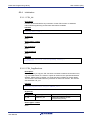
5.3.1.1 FSL_Init
Description
Function is executed before any execution of other FSL function. It initializes
internal Self-Programming environment and internal variables.
Interface
void FSL_Init( void )
Arguments
None
Return types / values
None
Pre-conditions
None
Post-conditions
None
Example
/* Initialze and start Self-Programming Library */
FSL_Init( );
5.3.1.2 FSL_CopySections
Description
If it is necessary to copy the FSL functions to another location than the linked one,
e.g. to a RAM location, the function copies all routines to the specified destination
address. Please refer to chapter 4.3 “Code execution in RAM” for further details.
The function is executed before any execution of other FSL function, but must be
executed after FSL_Init.
Interface
void FSL_CopySections( fsl_u32 addDest_u32 )
Arguments
Type
fsl_u32
Argument
addDest_u32
Description
Destination address of SelfProgramming Library
Return types / values
None
R01US0046ED Rev. 1.01
User Manual
28
Flash Self-Programming Library
User Interface (API)
Pre-conditions
Library must be initialized (call function FSL_Init).
Post-conditions
None
Example
/* Copy FSL to internal RAM address 0xffff7000 */
FSL_CopySections( 0xffff7000 );
5.3.1.3 FSL_CalcFctAddr
Description
Function calculates the new address of a function copied from ROM to RAM. To
locate the new address of the function, the copied function must be located in on
of the FSL linker segments (see chapter 3.2 “FSL Linker sections”).
Interface
fsl_u32 FSL_CalcFctAddr( void *pAddFct_ptr, fsl_u32 destAddr_u32 )
Arguments
Type
Argument
Description
void
pAddFct_ptr
Pointer to ROM address of copied
function
fsl_u32
destAdd_u32
Destination address of SelfProgramming Library, e.g. value used
for FSL_CopySections.
Return types / values
Type
fsl_u32
Argument
Description
New RAM address of function
Pre-conditions
Library must be initialized (call function FSL_Init) and copied (call function
FSL_CopySections).
Post-conditions
None
Example
/* Calculate new address of FSL_Write function */
/* FSL copied to RAM addess 0xffff7000 */
fsl_u32 (*fpFct)( void );
fpFct = (fsl_u32(*)())FSL_CalcFctAddr( ( void * )FSL_Write,
0xffff7000 );
R01US0046ED Rev. 1.01
User Manual
29
Flash Self-Programming Library
User Interface (API)
5.3.1.4 FSL_FlashEnv_Activate
Description
Function initializes the Flash control macro and activates and prepares the Flash
environment.
Interface
fsl_status_t FSL_FlashEnv_Activate( void )
Arguments
None
Return types / values
Type
Argument
fsl_status_t
Description
Operation status when returned from
function call:
FSL_OK
FSL_BUSY
FSL_ERR_FLOW
FSL_ERR_FLMD0
1
2
FSL_ERR_INTERNAL
1
Status check is performed internally by the firmware
2
Status check is performed by the user
1
Pre-conditions
Library must be initialized (call function FSL_Init) and copied (call function
FSL_CopySections).
Post-conditions
In case of user mode and activated polling, call FSL_StatusCheck till function
return value is different from FSL_BUSY.
Example
/* Enable Flash environment */
fsl_status_t
status_enu;
status_enu = FSL_FlashEnv_Activate( );
#ifdef FSL_ACTIVATION_POLLING
while( status_enu == FSL_BUSY )
{
status_enu = FSL_StatusCheck( );
}
#endif
/* Error treatment */
5.3.1.5 FSL_FlashEnv_Deactivate
Description
Function terminates all Flash operations and deactivates the Flash environment.
R01US0046ED Rev. 1.01
User Manual
30
Flash Self-Programming Library
User Interface (API)
Interface
fsl_status_t FSL_FlashEnv_Deactivate( void )
Arguments
None
Return types / values
Type
Argument
fsl_status_t
Description
Operation status when returned from
function call:
FSL_OK
FSL_BUSY
FSL_ERR_FLOW
FSL_ERR_FLMD0
1
2
FSL_ERR_INTERNAL
Status check is performed internally by the firmware
2
Status check is performed by the user
1
1
Pre-conditions
Library must be initialized (call function FSL_Init), copied (call function
FSL_CopySections) and active (call function FSL_FlashEnv_Activate).
Additionally the library must be informed about FBUS clock by using function
FSL_SetFrequency.
Post-conditions
In case of user mode and activated polling, call FSL_StatusCheck till function
return value is different from FSL_BUSY.
Example
/* Deactivate Flash environment */
fsl_status_t
status_enu;
status_enu = FSL_FlashEnv_Deactivate( );
#ifdef FSL_ACTIVATION_POLLING
while( status_enu == FSL_BUSY )
{
status_enu = FSL_StatusCheck( );
}
#endif
/* Error treatment */
...
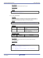
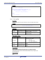
5.3.1.6 FSL_SetFrequency
Description
The function informs the Self-Programming routines about the configured CPU
frequency. A frequency fractional part need to be rounded up, e.g.: 25.3MHz
need to be rounded up to 26MHz.
CPU frequency setting condition:
The Flash programming hardware is provided with a clock, derived from the CPU
frequency. The frequency divider of this derived clock is device family dependent.
The resulting fFlash hardware must be in the range of 8 to 50MHz.
R01US0046ED Rev. 1.01
User Manual
31
Flash Self-Programming Library
User Interface (API)
E.g.: Fx4-L, Px4-L:
fFlash hardware = fCpu / 2
16MHz <= fCpu <= mimimum of <100MHz> or <maximum device frequency>
Caution: The CPU frequency must be set correctly. If not, malfunction may occur such as
unstable Flash data without data retention, programming failure, operation
blocking.
Interface
fsl_status_t FSL_SetFrequency( fsl_u32 FreqData_u32 )
Arguments
Type
fsl_u32
Argument
FreqData_u32
Description
Rounded up CPU clock in MHz
(boundaries see above)
Example: clock is 25.7MHz
→ FreqData_u32 = 26
Return types / values
Type
Argument
fsl_status_t
Description
Operation status when returned from
function call:
FSL_OK
FSL_BUSY
FSL_ERR_FLOW
FSL_ERR_PARAMETER
1
2
FSL_ERR_INTERNAL
1
Status check is performed internally by the firmware
2
Status check is performed by the user
1
Pre-conditions
Library must be initialized (call function FSL_Init), copied (call function
FSL_CopySections) and active (call function FSL_FlashEnv_Activate).
Post-conditions
In case of user mode and activated polling, call FSL_StatusCheck till function
return value is different from FSL_BUSY.
Example
/* Set clock to 32MHz */
fsl_status_t
status_enu;
status_enu = FSL_SetFrequency( 32 );
#if FSL_STATUS_CHECK == FSL_STATUS_CHECK_USER
while( status_enu == FSL_BUSY )
{
status_enu = FSL_StatusCheck( );
}
#endif
/* Error treatment */
...
R01US0046ED Rev. 1.01
User Manual
32
Flash Self-Programming Library
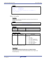
5.3.2
User Interface (API)
Operation
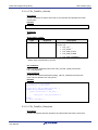
5.3.2.1 FSL_Erase
Description
Function erases a range of blocks.
Interface
fsl_status_t FSL_Erase( fsl_u32 blockNoStart_u32,
fsl_u32 blockNoEnd_u32 )
Arguments
Type
Argument
Description
fsl_u32
blockNoStart_u32
First block number to be erased. (It is
not the block address, but the number of
the Flash block.)
fsl_u32
blockNoEnd_u32
Last block number to be erased. (It is
not the block address, but the number of
the Flash block.)
Return types / values
Type
fsl_status_t
Argument
Description
Operation status when returned from
function call:
FSL_OK
FSL_BUSY
FSL_ERR_FLOW
FSL_ERR_PROTECTION
FSL_ERR_PARAMETER
FSL_ERR_ERASE
1
2
1
FSL_ERR_INTERNAL
Status check is performed internally by the firmware
2
Status check is performed by the user
1
1
Pre-conditions
Library must be initialized (call function FSL_Init), copied (call function
FSL_CopySections) and active (call function FSL_FlashEnv_Activate).
Additionally the library must be informed about FBUS clock by using function
FSL_SetFrequency.
Post-conditions
In case of user mode call FSL_StatusCheck till function return value is different
from FSL_BUSY.
R01US0046ED Rev. 1.01
User Manual
33
Flash Self-Programming Library
User Interface (API)
Example
/* Erase check block 3 to 20 */
fsl_status_t
status_enu;
status_enu = FSL_Erase( 3, 20 );
#if FSL_STATUS_CHECK == FSL_STATUS_CHECK_USER
while( status_enu == FSL_BUSY )
{
status_enu = FSL_StatusCheck( );
}
#endif
/* Error treatment */
...
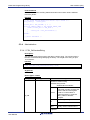
5.3.2.2 FSL_Write
Description
Function writes the specified number of words from a buffer to consecutive Flash
addresses starting at the specified address.
Interface
fsl_status_t FSL_Write( fsl_u32 *pAddSrc_pu32,
fsl_u32 addDest_u32,
fsl_u32 length_u32 )
Arguments
Type
Argument
Description
fsl_u32
pAddSrc_pu32
Pointer to buffer of data to be written
fsl_u32
addDest_u32
64 word aligned destination address of
data to be written
fsl_u32
length_u32
64 word aligned length of data in words
Return types / values
Type
fsl_status_t
Argument
Description
Operation status when returned from
function call:
FSL_OK
FSL_BUSY
FSL_ERR_FLOW
FSL_ERR_PROTECTION
FSL_ERR_PARAMETER
FSL_ERR_WRITE
1
2
1
FSL_ERR_INTERNAL
Status check is performed internally by the firmware
2
Status check is performed by the user
1
1
R01US0046ED Rev. 1.01
User Manual
34
Flash Self-Programming Library
User Interface (API)
Pre-conditions
Library must be initialized (call function FSL_Init), copied (call function
FSL_CopySections) and active (call function FSL_FlashEnv_Activate).
Additionally the library must be informed about FBUS clock by using function
FSL_SetFrequency.
Post-conditions
In case of user mode call FSL_StatusCheck till function return value is different
from FSL_BUSY.
Example
/* Write 64 words of data to address 0x00000000 onwards */
fsl_status_t status_enu;
fsl_u32
buf_u32[64];
/* fill buffer */
...
status_enu = FSL_Write( &buf_u32[0], 0x00000000, 64 );
#if FSL_STATUS_CHECK == FSL_STATUS_CHECK_USER
while( status_enu == FSL_BUSY )
{
status_enu = FSL_StatusCheck( );
}
#endif
/* Error treatment */
...
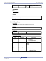
5.3.2.3 FSL_Read
Description
Function reads the specified number of words from consecutive Flash addresses
starting at the specified address and writes it into a buffer.
Interface
fsl_status_t FSL_Read( fsl_u32 addSrc_u32,
fsl_u32 *pDest_pu32,
fsl_u32 length_u32 )
Arguments
Type
Argument
Description
fsl_u32
addSrc_u32
Word aligned source address of data to
be read
fsl_u32
pDest_pu32
Pointer to buffer of read data
fsl_u32
length_u32
Word aligned length of data in words
Return types / values
Type
fsl_status_t
R01US0046ED Rev. 1.01
User Manual
Argument
Description
Operation status when returned from
function call:
FSL_OK
FSL_BUSY
1
2
35
Flash Self-Programming Library
fsl_u32
1
2
User Interface (API)
pDest
FSL_ERR_FLOW
FSL_ERR_PARAMETER
FSL_ERR_INTERNAL
1
Pointer to buffer filled with read data
Status check is performed internally by the firmware
Status check is performed by the user
Pre-conditions
Library must be initialized (call function FSL_Init), copied (call function
FSL_CopySections) and active (call function FSL_FlashEnv_Activate).
Additionally the library must be informed about FBUS clock by using function
FSL_SetFrequency.
Post-conditions
In case of user mode call FSL_StatusCheck till function return value is different
from FSL_BUSY.
Example
/* Read 64 words from address 0x00000000 onwards */
fsl_status_t
status_enu;
fsl_u32
buf_u32[64];
status_enu = FSL_Read( 0x00000000, &buf_u32[0], 64 );
#if FSL_STATUS_CHECK == FSL_STATUS_CHECK_USER
while( status_enu == FSL_BUSY )
{
status_enu = FSL_StatusCheck( );
}
#endif
/* Error treatment */
...
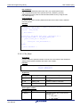
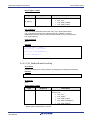
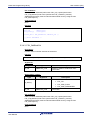
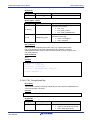
5.3.2.4 FSL_StatusCheck
Description
This function handles the complete state machine. It shall be called frequently,
but the calling style depends on the user application (refer to chapter 4.4 User
code execution during Self-Programming).
Note This command is only available in the user mode.
Interface
fsl_status_t FSL_StatusCheck( void )
Arguments
None
Return types / values
Type
fsl_status_t
R01US0046ED Rev. 1.01
User Manual
Argument
Description
Function return values:
FSL_OK
FSL_IDLE
36
Flash Self-Programming Library
User Interface (API)
FSL_BUSY
FSL_ERR_FLOW
FSL_ERR_ERASE
FSL_ERR_WRITE
FSL_ERR_INTERNAL
Pre-conditions
Library must be initialized (call function FSL_Init), copied (call function
FSL_CopySections) and active (call function FSL_FlashEnv_Activate).
Additionally the library must be informed about FBUS clock by using function
FSL_SetFrequency.
Post-conditions
None
Example
/* Show FSL_StatusCheck usage */
fsl_status_t
status_enu;
/* start some FSL operation (e.g. FSL_Erase ) */
status_enu = FSL_Erase( 3, 20 );
/* Status Check */
#if FSL_STATUS_CHECK == FSL_STATUS_CHECK_USER
while( status_enu == FSL_BUSY )
{
status_enu = FSL_StatusCheck( );
}
#endif
/* Error treatment */
...
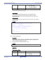
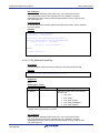
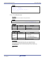
5.3.3
Security
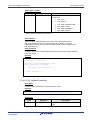
5.3.3.1 FSL_GetSecurityFlags
Description
Function reads stored security information.
Interface
fsl_status_t FSL_GetSecurityFlags( fsl_u32 *pFlags_pu32 )
Arguments
Type
fsl_u32
R01US0046ED Rev. 1.01
User Manual
Argument
pFlags_pu32
Description
Pointer to buffer of read security
information
37
Flash Self-Programming Library
User Interface (API)
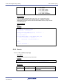
Return types / values
Type
Argument
Description
Function return values:
fsl_status_t
FSL_OK
FSL_ERR_FLOW
FSL_ERR_PARAMETER
Pointer to buffer filled with bit
coded security information
fsl_u32
pFlags_pu32
x1xxxx : Read permission
x0xxxx : Read prohibition
xx1xxx : Write permission
xx0xxx : Write prohibition
xxxx1x : Block erase permission
xxxx0x : Block erase prohibition
xxxxx1 : Permission of boot
block cluster programming
xxxxx0 : Prohibition of boot
block cluster programming
Pre-conditions
Library must be initialized (call function FSL_Init), copied (call function
FSL_CopySections) and active (call function FSL_FlashEnv_Activate).
Additionally the library must be informed about FBUS clock by using function
FSL_SetFrequency.
Post-conditions
None
Example
/* Read security flags */
fsl_u32
flags_u32;
fsl_status_t
status_enu;
status_enu = FSL_GetSecurityFlags( &flags_u32 );
/* Error treatment */
...
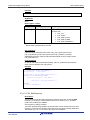
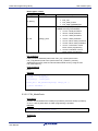
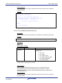
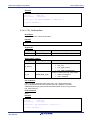
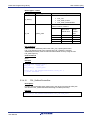
5.3.3.2 FSL_ModeCheck
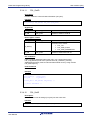
Description
Function checks whether the FLMD0 pin (hardware protection shield) is pulled up
or not. In case of pulled down no Flash programming is possible.
Interface
fsl_status_t FSL_ModeCheck( void )
Arguments
None
R01US0046ED Rev. 1.01
User Manual
38
Flash Self-Programming Library
User Interface (API)
Return types / values
Type
Argument
Description
Function return values:
fsl_status_t
FSL_OK
FSL_ERR_FLMD0
FSL_ERR_FLOW
Pre-conditions
Library must be initialized (call function FSL_Init), copied (call function
FSL_CopySections) and active (call function FSL_FlashEnv_Activate).
Additionally the library must be informed about FBUS clock by using function
FSL_SetFrequency.
Post-conditions
None
Example
/* Check level of FLMD0 */
fsl_status_t
status_enu;
status_enu = FSL_ModeCheck( );
/* Error treatment */
...
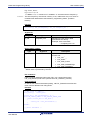
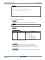
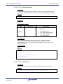
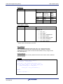
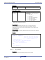
5.3.3.3 FSL_SetBlockEraseProtectFlag
Description
Function enables block erase protection by setting the according protection flag.
Interface
fsl_status_t FSL_SetBlockEraseProtectFlag( void )
Arguments
None
Return types / values
Type
fsl_status_t
Argument
Description
Operation status when returned from
function call:
FSL_OK
FSL_BUSY
FSL_ERR_FLOW
FSL_ERR_INTERNAL
1
2
FSL_ERR_WRITE
Status check is performed internally by the firmware
2
Status check is performed by the user
1
1
1
R01US0046ED Rev. 1.01
User Manual
39
Flash Self-Programming Library
User Interface (API)
Pre-conditions
Library must be initialized (call function FSL_Init), copied (call function
FSL_CopySections) and active (call function FSL_FlashEnv_Activate).
Additionally the library must be informed about FBUS clock by using function
FSL_SetFrequency.
Post-conditions
In case of user mode call FSL_StatusCheck till function return value is different
from FSL_BUSY.
Example
/* Set block erase protection */
fsl_status_t
status_enu;
status_enu = FSL_SetBlockEraseProtectFlag( );
#if FSL_STATUS_CHECK == FSL_STATUS_CHECK_USER
while( status_enu == FSL_BUSY )
{
status_enu = FSL_StatusCheck( );
}
#endif
/* Error treatment */
...
5.3.3.4 FSL_SetWriteProtectFlag
Description
Function enables write protection by setting the according protection flag.
Interface
fsl_status_t FSL_SetWriteProtectFlag( void )
Arguments
None
Return types / values
Type
fsl_status_t
Argument
Description
Operation status when returned from
function call:
FSL_OK
FSL_BUSY
FSL_ERR_FLOW
FSL_ERR_INTERNAL
1
2
FSL_ERR_WRITE
Status check is performed internally by the firmware
2
Status check is performed by the user
1
1
1
Pre-conditions
Library must be initialized (call function FSL_Init), copied (call function
FSL_CopySections) and active (call function FSL_FlashEnv_Activate).
Additionally the library must be informed about FBUS clock by using function
FSL_SetFrequency.
R01US0046ED Rev. 1.01
User Manual
40
Flash Self-Programming Library
User Interface (API)
Post-conditions
In case of user mode call FSL_StatusCheck till function return value is different
from FSL_BUSY.
Example
/* Set write protection */
fsl_status_t
status_enu;
status_enu = FSL_SetWriteProtectFlag( );
#if FSL_STATUS_CHECK == FSL_STATUS_CHECK_USER
while( status_enu == FSL_BUSY )
{
status_enu = FSL_StatusCheck( );
}
#endif
/* Error treatment */
...
5.3.3.5 FSL_SetBootClusterProtectFlag
Description
Function enables boot cluster protection by setting the according protection flag.
Interface
fsl_status_t FSL_SetBootClusterProtectFlag( void )
Arguments
None
Return types / values
Type
fsl_status_t
Argument
Description
Operation status when returned from
function call:
FSL_OK
FSL_BUSY
FSL_ERR_FLOW
FSL_ERR_PROTECTION
FSL_ERR_INTERNAL
1
2
FSL_ERR_WRITE
Status check is performed internally by the firmware
2
Status check is performed by the user
1
1
1
Pre-conditions
Library must be initialized (call function FSL_Init), copied (call function
FSL_CopySections) and active (call function FSL_FlashEnv_Activate).
Additionally the library must be informed about FBUS clock by using function
FSL_SetFrequency.
Post-conditions
In case of user mode call FSL_StatusCheck till function return value is different
from FSL_BUSY.
R01US0046ED Rev. 1.01
User Manual
41
Flash Self-Programming Library
User Interface (API)
Example
/* Set boot cluster protection */
fsl_status_t status_enu;
status_enu = FSL_SetBootClusterProtectFlag( );
#if FSL_STATUS_CHECK == FSL_STATUS_CHECK_USER
while( status_enu == FSL_BUSY )
{
status_enu = FSL_StatusCheck( );
}
#endif
/* Error treatment */
...
5.3.3.6 FSL_SetReadProtectFlag
Description
Function enables read protection by setting the according protection flag.
Interface
fsl_status_t FSL_SetReadProtectFlag( void )
Arguments
None
Return types / values
Type
fsl_status_t
Argument
Description
Operation status when returned from
function call:
FSL_OK
FSL_BUSY
FSL_ERR_FLOW
FSL_ERR_INTERNAL
1
2
FSL_ERR_WRITE
Status check is performed internally by the firmware
2
Status check is performed by the user
1
1
1
Pre-conditions
Library must be initialized (call function FSL_Init), copied (call function
FSL_CopySections) and active (call function FSL_FlashEnv_Activate).
Additionally the library must be informed about FBUS clock by using function
FSL_SetFrequency.
Post-conditions
In case of user mode call FSL_StatusCheck till function return value is different
from FSL_BUSY.
R01US0046ED Rev. 1.01
User Manual
42
Flash Self-Programming Library
User Interface (API)
Example
/* Set read protection */
fsl_status_t
status_enu;
status_enu = FSL_SetReadProtectFlag( );
#if FSL_STATUS_CHECK == FSL_STATUS_CHECK_USER
while( status_enu == FSL_BUSY )
{
status_enu = FSL_StatusCheck( );
}
#endif
/* Error treatment */
...
5.3.3.7 FSL_GetFSW
Description
Function returns the start and the end block of the actual Flash shield window.
Interface
fsl_status_t FSL_GetFSW( fsl_u32 *pBlockNoStart_pu32,
fsl_u32 *pBlockNoEnd_pu32 )
Arguments
Type
Argument
Description
fsl_u32
pBlockNoStart_pu32
Pointer to buffer for starting block
number of FSW
fsl_u32
pBlockNoEnd_pu32
Pointer to buffer for ending block
number of FSW
Return types / values
Type
Argument
Description
Function return values:
fsl_status_t
FSL_OK
FSL_ERR_FLOW
FSL_ERR_PARAMETER
fsl_u32
pBlockNoStart_pu32
Buffer including starting block number of
FSW
fsl_u32
pBlockNoEnd_pu32
Buffer including ending block number of
FSW
Pre-conditions
Library must be initialized (call function FSL_Init), copied (call function
FSL_CopySections) and active (call function FSL_FlashEnv_Activate).
Additionally the library must be informed about FBUS clock by using function
FSL_SetFrequency.
Post-conditions
None
R01US0046ED Rev. 1.01
User Manual
43
Flash Self-Programming Library
User Interface (API)
Example
/* Read Flash Shield Window range */
fsl_status_t
status_enu;
fsl_u32
blockStart_u32;
fsl_u32
blockEnd_u32;
status_enu = FSL_GetFSW( &blockStart_u32, &blockEnd_u32 );
/* Error treatment */
...
5.3.3.8 FSL_SetFSW
Description
Function sets a new Flash shield window to protect the range of blocks from
unwanted Flash operations.
Interface
fsl_status_t FSL_SetFSW( fsl_u32 blockNoStart_u32,
fsl_u32 blockNoEnd_u32 )
Arguments
Type
Argument
Description
fsl_u32
BlockNoStart_u32
Starting block number of FSW
fsl_u32
BlockNoEnd_u32
Ending block number of FSW
Return types / values
Type
fsl_status_t
Argument
Description
Operation status when returned from
function call:
FSL_OK
FSL_BUSY
FSL_ERR_PARAMETER
FSL_ERR_PROTECTION
FSL_ERR_FLOW
FSL_ERR_INTERNAL
1
2
FSL_ERR_WRITE
Status check is performed internally by the firmware
2
Status check is performed by the user
1
1
1
Pre-conditions
Library must be initialized (call function FSL_Init), copied (call function
FSL_CopySections) and active (call function FSL_FlashEnv_Activate).
Additionally the library must be informed about FBUS clock by using function
FSL_SetFrequency.
R01US0046ED Rev. 1.01
User Manual
44
Flash Self-Programming Library
User Interface (API)
Post-conditions
In case of user mode call FSL_StatusCheck till function return value is different
from FSL_BUSY.
Example
/* Set Flash Shield Window for block 2 up to block 3 */
fsl_status_t
status_enu;
status_enu = FSL_SetFSW( 2, 3 );
#if FSL_STATUS_CHECK == FSL_STATUS_CHECK_USER
while( status_enu == FSL_BUSY )
{
status_enu = FSL_StatusCheck( );
}
#endif
/* Error treatment */
...
5.3.4
Administration
5.3.4.1 FSL_GetVersionString
Description
This function returns the pointer to the library version string. The version string is
the zero terminated string identifying the library. The length of the string is up to
19 characters.
Interface
const fsl_u08* FSL_GetVersionString( void )
Arguments
None
Return types / values
Type
Argument
Description
Pointer to version string
Version string format:
“SV850T06xxxxxYabcde”
xxxxx
fsl_u08
Coded information about the
supported compiler including the
version and the used register
model. If no information is
coded, the library is a generic
library valid for different
compiler.
“E” for engineering version
Y
abc
“V” for final version
Library version number Va.b.c.
optional:
R01US0046ED Rev. 1.01
User Manual
45
Flash Self-Programming Library
User Interface (API)
customer specific version
information
de
Pre-conditions
None
Post-conditions
None
Example
/* Read library version */
fsl_u08
*version_pu08;
version_pu08 = FSL_GetVersionString( );
5.3.4.2 FSL_GetDevice
Description
Function returns the device number to identify the used device.
Interface
fsl_status_t FSL_GetDevice( fsl_u32 *pDeviceNo_pu32 )
Arguments
Type
fsl_u32
Argument
pDeviceNo_pu32
Description
Pointer to buffer of read device number
Return types / values
Type
Argument
Description
Function return values:
fsl_status_t
fsl_u32
R01US0046ED Rev. 1.01
User Manual
pDeviceNo_pu32
FSL_OK
FSL_ERR_FLOW
FSL_ERR_PARAMETER
Pointer to buffer filled with device
number
Format:
“0000000000000000xxxxxxxxxxxxxxxx”
Example:
uPD70F3377
→3377 = 0x0D31
→xxxxxxxxxxxxxxxx =
000110100110001
46
Flash Self-Programming Library
User Interface (API)
Pre-conditions
Library must be initialized (call function FSL_Init), copied (call function
FSL_CopySections) and active (call function FSL_FlashEnv_Activate).
Additionally the library must be informed about FBUS clock by using function
FSL_SetFrequency.
Post-conditions
None
Example
/* Read device name */
fsl_u32
device_u32;
fsl_status_t
status_enu;
status_enu = FSL_GetDevice( &device_u32 );
/* Error treatment */
...
5.3.4.3 FSL_GetBlockCnt
Description
Function returns number of blocks of the device.
Interface
fsl_ status_t FSL_GetBlockCnt( fsl_u32 *pBlockCnt_pu32 )
Arguments
Type
fsl_u32
Argument
pBlockCnt_pu32
Description
Pointer to buffer of read block count
information
Return types / values
Type
Argument
Description
Function return values:
fsl_status_t
fsl_u32
pBlockCnt_pu32
FSL_OK
FSL_ERR_FLOW
FSL_ERR_PARAMETER
Pointer to buffer filled with block count
information
Pre-conditions
Library must be initialized (call function FSL_Init), copied (call function
FSL_CopySections) and active (call function FSL_FlashEnv_Activate).
Additionally the library must be informed about FBUS clock by using function
FSL_SetFrequency.
Post-conditions
None
R01US0046ED Rev. 1.01
User Manual
47
Flash Self-Programming Library
User Interface (API)
Example
/* Read block count */
fsl_u32
cnt_u32;
fsl_status_t
status_enu;
status_enu = FSL_GetBlockCnt( &cnt_u32 );
/* Error treatment */
...
5.3.4.4 FSL_GetBlockEndAdd
Description
Function returns the end address of the specified block.
Interface
fsl_status_t FSL_GetBlockEndAdd( fsl_u32 blockNo_u32,
fsl_u32 *pBlockEndAddr_pu32)
Arguments
Type
Argument
Description
fsl_u32
blockNo_u32
Block number
fsl_u32
pBlockEndAddr_pu32
Pointer to buffer of read block end
address information
Return types / values
Type
Argument
Description
Function return values:
fsl_status_t
fsl_u32
pBlockEndAddr_pu32
FSL_OK
FSL_ERR_FLOW
FSL_ERR_PARAMETER
Pointer to buffer filled with requested
end address of the block
Pre-conditions
Library must be initialized (call function FSL_Init), copied (call function
FSL_CopySections) and active (call function FSL_FlashEnv_Activate).
Additionally the library must be informed about FBUS clock by using function
FSL_SetFrequency.
Post-conditions
None
R01US0046ED Rev. 1.01
User Manual
48
Flash Self-Programming Library
User Interface (API)
Example
/* Read block end address of block 3*/
fsl_u32
addr_u32;
fsl_status_t
status_enu;
status_enu = FSL_GetBlockEndAdd( 3, &addr_u32 );
/* Error treatment */
...
5.3.4.5 FSL_GetSwapState
Description
Function reads the current swap status.
Interface
fsl_status_t FSL_GetSwapState ( fsl_u32 *pSwapState_pu32 )
Arguments
Type
fsl_u32
Argument
pSwapState_pu32
Description
Pointer to buffer of read swap status
Return types / values
Type
Argument
Description
Function return values:
fsl_status_t
FSL_OK
FSL_ERR_FLOW
FSL_ERR_PARAMETER
Pointer to buffer filled with swap status:
fsl_u32
pSwapState_pu32
0x00: not swapped
0x01: swapped
Pre-conditions
Library must be initialized (call function FSL_Init), copied (call function
FSL_CopySections) and active (call function FSL_FlashEnv_Activate).
Additionally the library must be informed about FBUS clock by using function
FSL_SetFrequency.
Post-conditions
None
Example
/* Read boot cluster */
fsl_u32
state_u32
fsl_status_t
status_enu
status_enu = FSL_GetSwapState( &state_u32 );
/* Error treatment */
...
R01US0046ED Rev. 1.01
User Manual
49
Flash Self-Programming Library
User Interface (API)
5.3.4.6 FSL_ChangeSwapState
Description
Function swaps the boot cluster 0 and boot cluster 1 physically without setting
the boot flag. After reset the boot cluster will be activated regarding the boot flag.
Interface
fsl_status_t FSL_ChangeSwapState( void )
Arguments
None
Return types / values
Type
Argument
Description
Function return values:
fsl_status_t
FSL_OK
FSL_ERR_FLOW
FSL_ERR_PROTECTION
FSL_ERR_INTERNAL
FSL_ERR_WRITE
Pre-conditions
Library must be initialized (call function FSL_Init), copied (call function
FSL_CopySections) and active (call function FSL_FlashEnv_Activate).
Additionally the library must be informed about FBUS clock by using function
FSL_SetFrequency.
Post-conditions
None
Example
/* Swap boot cluster */
fsl_status_t
status_enu;
status_enu = FSL_ChangeSwapState( );
/* Error treatment */
...
5.3.4.7 FSL_GetSwapFlag
Description
Function reads the current value of the boot swap flag from the extra area.
Interface
fsl_status_t FSL_GetSwapFlag ( fsl_u32 *pSwapFlag_pu32 )
R01US0046ED Rev. 1.01
User Manual
50
Flash Self-Programming Library
User Interface (API)
Arguments
Type
fsl_u32
Argument
pSwapFlag_pu32
Description
Pointer to buffer of read swap flag
Return types / values
Type
Argument
Description
Function return values:
fsl_status_t
FSL_OK
FSL_ERR_FLOW
FSL_ERR_PARAMETER
Pointer to buffer filled with current value
of the boot swap flag:
fsl_u32
pSwapFlag_pu32
0x00: not swapped
0x01: swapped
Pre-conditions
Library must be initialized (call function FSL_Init), copied (call function
FSL_CopySections) and active (call function FSL_FlashEnv_Activate).
Additionally the library must be informed about FBUS clock by using function
FSL_SetFrequency.
Post-conditions
None
Example
/* Read boot cluster */
fsl_u32
flag_u32;
fsl_status_t
status_enu
status_enu = FSL_GetSwapFlag( &flag_u32 );
/* Error treatment */
...
5.3.4.8 FSL_ChangeSwapFlag
Description
The function inverts the bootswap. Depending on the parameter, additionally the
current swap state is inverted.
Interface
fsl_status_t FSL_ChangeSwapFlag( fsl_u32 immediateSwap_u32 )
Arguments
Type
fsl_u32
R01US0046ED Rev. 1.01
User Manual
Argument
immediateSwap_u32
Description
Swap boot cluster immediately:
0x00: Do not swap boot cluster
0x01: Swap boot cluster
51
Flash Self-Programming Library
User Interface (API)
Return types / values
Type
Argument
fsl_status_t
Description
Operation status when returned from
function call:
FSL_OK
FSL_BUSY
FSL_ERR_PROTECTION
FSL_ERR_FLOW
FSL_ERR_INTERNAL
1
2
FSL_ERR_WRITE
Status check is performed internally by the firmware
2
Status check is performed by the user
1
1
1
Pre-conditions
Library must be initialized (call function FSL_Init), copied (call function
FSL_CopySections) and active (call function FSL_FlashEnv_Activate).
Additionally the library must be informed about FBUS clock by using function
FSL_SetFrequency.
Post-conditions
In case of user mode call FSL_StatusCheck till function return value is different
from FSL_BUSY.
Example
/* Swap the boot flag, but do not generate a reset signal */
fsl_status_t
status_enu;
status_enu = FSL_ChangeSwapFlag( 0x00 );
while( status_enu == FSL_BUSY )
{
status_enu = FSL_StatusCheck( );
}
/* Error treatment */
...
5.3.4.9 FSL_GetBootClusterSize
Description
Function reads current size of protectable boot cluster.
Interface
fsl_status_t FSL_GetBootClusterSize( fsl_u32 *pSize_pu32 )
Arguments
Type
fsl_u32
R01US0046ED Rev. 1.01
User Manual
Argument
pSize_pu32
Description
Pointer to buffer of read boot cluster
size
52
Flash Self-Programming Library
User Interface (API)
Return types / values
Type
Argument
Description
Function return values:
fsl_status_t
FSL_OK
FSL_ERR_FLOW
FSL_ERR_PARAMETER
Pointer to buffer filled with boot cluster
size in number of blocks.
size_u32
fsl_u32
Boot Block
Cluster size
Boot
Swap
Cluster
size
0x00
32KB
32KB
0x01
64KB
64KB
0x02-0x03
96-128KB
128KB
0x04-0xE3
160-7296KB
256KB
pSize_pu32
Pre-conditions
Library must be initialized (call function FSL_Init), copied (call function
FSL_CopySections) and active (call function FSL_FlashEnv_Activate).
Additionally the library must be informed about FBUS clock by using function
FSL_SetFrequency.
Post-conditions
None
Example
/* Read boot cluster size */
fsl_u32
size_u32;
fsl_status_t
status_enu;
status_enu = FSL_GetBootClusterSize( &size_u32 );
/* Error treatment */
...
5.3.4.10
FSL_SetBootClusterSize
Description
Function sets protectable boot cluster size in the range from 0x00 to 0xE3 (see
also function FSL_SetBootClusterProtectFlag to enable protection).
Interface
fsl_status_t FSL_SetBootClusterSize( fsl_u32 size_u32 )
R01US0046ED Rev. 1.01
User Manual
53
Flash Self-Programming Library
User Interface (API)
Arguments
Type
fsl_u32
Argument
size_u32
Description
Boot cluster size (range: 0x00-0xE3)
size_u32
Boot Block
Cluster size
Boot
Swap
Cluster
size
0x00
32KB
32KB
0x01
64KB
64KB
0x02-0x03
96-128KB
128KB
0x04-0xE3
160-7296KB
256KB
Return types / values
Type
Argument
fsl_status_t
Description
Operation status when returned from
function call:
FSL_OK
FSL_BUSY
FSL_ERR_PARAMETER
FSL_ERR_FLOW
FSL_ERR_PROTECTION
FSL_ERR_INTERNAL
1
2
FSL_ERR_WRITE
Status check is performed internally by the firmware
2
Status check is performed by the user
1
1
1
Pre-conditions
Library must be initialized (call function FSL_Init), copied (call function
FSL_CopySections) and active (call function FSL_FlashEnv_Activate).
Additionally the library must be informed about FBUS clock by using function
FSL_SetFrequency.
Post-conditions
In case of user mode call FSL_StatusCheck till function return value is different
from FSL_BUSY.
Example
/* Set boot cluster size to 0x04 */
fsl_status_t
status_enu;
status_enu = FSL_SetBootClusterSize( 0x04 );
#if FSL_STATUS_CHECK == FSL_STATUS_CHECK_USER
while( status_enu == FSL_BUSY )
{
status_enu = FSL_StatusCheck( );
}
#endif
/* Error treatment */
...
R01US0046ED Rev. 1.01
User Manual
54
Flash Self-Programming Library
5.3.4.11
User Interface (API)
FSL_GetID
Description
Function reads the current ID data information (12 bytes).
Interface
fsl_status_t FSL_GetID( fsl_u08 *pID_pu08 )
Arguments
Type
fsl_u08
Argument
pID_pu08
Description
Pointer to buffer of read ID
Return types / values
Type
Argument
Description
Function return values:
fsl_status_t
fsl_u08
pID_pu08
FSL_OK
FSL_ERR_FLOW
FSL_ERR_PARAMETER
Pointer to buffer filled with ID
Pre-conditions
Library must be initialized (call function FSL_Init), copied (call function
FSL_CopySections) and active (call function FSL_FlashEnv_Activate).
Additionally the library must be informed about FBUS clock by using function
FSL_SetFrequency.
Post-conditions
None
Example
/* Read ID */
fsl_status_t
fsl_u08
status_enu;
id_u08[12];
status_enu = FSL_GetID( &id_u08[0] );
/* Error treatment */
...
5.3.4.12
FSL_SetID
Description
Function writes new ID settings (12 bytes) into the extra area.
Interface
fsl_status_t FSL_SetID( fsl_u08 *pID_pu08 )
R01US0046ED Rev. 1.01
User Manual
55
Flash Self-Programming Library
User Interface (API)
Arguments
Type
fsl_u32
Argument
Description
pID_pu32
Pointer to source data of ID
Return types / values
Type
Argument
Description
fsl_status_t
Operation status when returned from
function call:
FSL_OK
FSL_BUSY
FSL_ERR_PARAMETER
FSL_ERR_FLOW
FSL_ERR_INTERNAL
1
2
FSL_ERR_WRITE
Status check is performed internally by the firmware
2
Status check is performed by the user
1
1
1
Pre-conditions
Library must be initialized (call function FSL_Init), copied (call function
FSL_CopySections) and active (call function FSL_FlashEnv_Activate).
Additionally the library must be informed about FBUS clock by using function
FSL_SetFrequency.
Post-conditions
In case of user mode call FSL_StatusCheck till function return value is different
from FSL_BUSY.
Example
/* Write ID */
fsl_status_t
status_enu;
fsl_u08
id_u08[] = {
0x00, 0x01, 0x02, 0x03, 0x04, 0x05,
0x06, 0x07, 0x08, 0x09, 0x0A, 0x8B
};
/* OCD on -> bit 95 = 1 */
FSL_SetID( &id_u08[0] );
#if FSL_STATUS_CHECK == FSL_STATUS_CHECK_USER
while( status == FSL_BUSY )
{
status = FSL_StatusCheck( );
}
#endif
/* Error treatment */
...
5.3.4.13
FSL_GetOPB
Description
Function reads current OPB settings (4 bytes) from the device.
R01US0046ED Rev. 1.01
User Manual
56
Flash Self-Programming Library
User Interface (API)
Interface
fsl_status_t FSL_GetOPB( fsl_u08 *pOPB_pu08 )
Arguments
Type
fsl_u08
Argument
pOPB_pu08
Description
Pointer to buffer of read option byte
Return types / values
Type
Argument
Description
Function return values:
fsl_status_t
fsl_u08
pOPB_pu08
FSL_OK
FSL_ERR_FLOW
FSL_ERR_PARAMETER
Pointer to buffer filled with option byte
Pre-conditions
Library must be initialized (call function FSL_Init), copied (call function
FSL_CopySections) and active (call function FSL_FlashEnv_Activate).
Additionally the library must be informed about FBUS clock by using function
FSL_SetFrequency.
Post-conditions
None
Example
/* Read option byte */
fsl_status_t
status_enu;
fsl_u08
data_u08[4];
status_enu = FSL_GetOPB( &data_u08[0] );
/* Error treatment */
...
5.3.4.14
FSL_SetOPB
Description
Function writes new OPB settings (4 bytes) into the extra area.
Interface
fsl_status_t FSL_SetOPB( fsl_u08 *pOPB_pu08 )
Arguments
Type
fsl_u08
R01US0046ED Rev. 1.01
User Manual
Argument
pOPB_pu08
Description
Pointer to source data of option bytes
57
Flash Self-Programming Library
User Interface (API)
Return types / values
Type
Argument
fsl_status_t
Description
Operation status when returned from
function call:
FSL_OK
FSL_BUSY
FSL_ERR_PARAMETER
FSL_ERR_FLOW
FSL_ERR_INTERNAL
1
2
FSL_ERR_WRITE
Status check is performed internally by the firmware
2
Status check is performed by the user
1
1
1
Pre-conditions
Library must be initialized (call function FSL_Init), copied (call function
FSL_CopySections) and active (call function FSL_FlashEnv_Activate).
Additionally the library must be informed about FBUS clock by using function
FSL_SetFrequency.
Post-conditions
In case of user mode call FSL_StatusCheck till function return value is different
from FSL_BUSY.
Example
/* Write option byte */
fsl_status_t
status_enu;
fsl_u08
data_u08[4] = { 0xFF, 0xFF, 0xFF, 0xFF};
FSL_SetOPB( &data_u08[0] );
#if FSL_STATUS_CHECK == FSL_STATUS_CHECK_USER
while( status_enu == FSL_BUSY )
{
status_enu = FSL_StatusCheck( );
}
#endif
/* Error treatment */
...
R01US0046ED Rev. 1.01
User Manual
58
Flash Self-Programming Library
Chapter 6
Integration into the user application
Integration into the user application
6.1 First steps
It is very important to have theoretic background about the Code Flash and the
FSL in order to successfully implement the library into the user application.
Therefore it is important to read this user manual in advance. The best way after
initial reading of the user manual will be testing the FSL application sample.
6.2 Application sample
After a first compile run, it will be worth playing around with the library in the
debugger. By that you will get a feeling for the source code files and the working
mechanism of the library.
Note: Before the first compile run, the compiler path must be configured in the
application sample file “makefile”:
Set the variable COMPILER_INSTALL_DIR to the correct compiler directory
Later on, the sample might be reconfigured to use the internal mode to get a
feeling of the CPU load and execution time during different modes.
After this exercise it might be easier to understand and follow the
recommendations and considerations of this document
6.3 FSL life cycle
The following flow charts represent typical FSL life cycles during device operation
including the API functions to be used.
Note Error treatment of the FSL function themselves are not detailed described in the
flow chart for simplification of the flow charts.
R01US0046ED Rev. 1.01
User Manual
59
Flash Self-Programming Library
Integration into the user application
Device reprogramming in user mode
Figure 6-1
Start reprogramming
FSL_Init
Initialization
phase
FSL_CopySections
FSL_FlashEnv_Activate
FSL_SetFrequency
Y
FSL_StatusCheck ==
FSL_BUSY ?
N
FSL_Erase
Normal
operation
Y
FSL_StatusCheck ==
FSL_BUSY ?
N
Error == FSL_OK ?
N
Error treatment
Y
Fill buffer
FSL_Write
Y
FSL_StatusCheck ==
FSL_BUSY ?
N
Error == FSL_OK ?
N
Error treatment
Y
N
All data written ?
Y
Deactivation
phase
FSL_FlashEnv_Deactivate
Stop reprogramming
Reprogramming flow – user mode
R01US0046ED Rev. 1.01
User Manual
60
Flash Self-Programming Library
Integration into the user application
Device reprogramming in internal mode
Figure 6-2
Start reprogramming
FSL_Init
Initialization
phase
FSL_CopySections
FSL_SetFrequency
Normal
operation
FSL_Erase
Error == FSL_OK ?
N
Error treatment
Y
Fill buffer
FSL_Write
Error == FSL_OK ?
N
Error treatment
Y
N
All data written ?
Y
Deactivation
phase
FSL_FlashEnv_Deactivate
Stop reprogramming
Reprogramming flow – internal mode
6.4 Special considerations
Due to the underlying hard- and software concepts, the user application must
take care of some constrains if using the library.
Function re-entrancy
All functions are not re-entrant. So, re-entrant calls of any FSL functions must be
avoided
Entering power safe mode
Entering power safe modes is prohibited during Self-Programming.
R01US0046ED Rev. 1.01
User Manual
61
Flash Self-Programming Library
Integration into the user application
Code Flash access during Self-Programming
Code Flash accesses during an active Self-Programming Environment are not
possible at all. The user application needs to be executed from other memory
during that time. Please refer to chapter 4.4 “User code execution during SelfProgramming” for further information.
R01US0046ED Rev. 1.01
User Manual
62
Flash Self-Programming Library
Integration into the user application
Revision History
Chapter
Page
Description
Rev 1.00
Initial version
Rev 1.01
Updated frequency setting description
R01US0046ED Rev. 1.01
User Manual
63
Flash Self-Programming Library
R01US0046ED