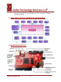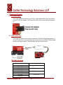
1
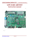
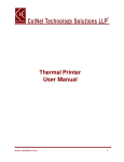
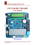
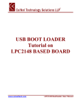
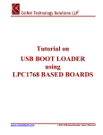
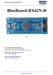
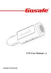
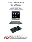
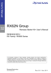
RX62N BOARD User Manual www.coineltech.com 1 Designed by CoiNel Technology Solutions LLP No-32 (Old No - 1355), 2nd Floor, HAPBCO Tower, 9th Main, 4th B Cross, Hampinagar, RPC Layout Bangalore – 560104 State: Karnataka Country: India www.coineltech.com Designations used by companies to distinguish their products are often claimed as trademarks. In all instances where CoiNel is aware of trademark claim, the product name appears in initial capital letters, in all capital or in accordance with the vendor’s capitalization preference. Users should contact appropriate companies for more complete information on trademark and trademark registrations. All trademarks and registered trademarks in this manual are the property of their respective holders. No part of this document may be reproduced or distributed in any form or by any means, or stored in the database or retrieval system, without the prior written permission from CoiNel Technology Solutions LLP; with the exception that the listings may be entered, stored and executed in a computer system, but they may not be reproduced. The content in this document are presented for instruction value. The details have been carefully tested, but are not guaranteed for any particular purpose. CoiNel Technology Solutions does not offer any warranties and does not guarantee the accuracy, adequacy, or completeness of any information herein and is not responsible for any errors or omissions. CoiNel Technology Solutions LLP assumes no liability for damages resulting from use of such information in this document or for any infringement of intellectual property rights of third parties that would result from use of this information. CoiNel Technology Solutions LLP assumes no liability for applications assistance, customer product design, software performance, or infringement of patents or services described herein. For any enquires, kindly contact [email protected] www.coineltech.com 2 TABLE OF CONTENTS Page # 1.0 Introduction ........................................................................................................................4 1.1 1.2 1.3 1.4 2.0 Peripheral Details ...............................................................................................................6 2.1 2.2 2.3 2.4 2.5 2.6 2.7 2.8 2.9 2.10 3.0 RX62N Board Features..............................................................................................4 RX62N Board Use Requirements ..............................................................................4 Functional Block Diagram of RX62N.........................................................................5 Board Description ......................................................................................................5 DC Power Input .........................................................................................................6 JTAG Connector........................................................................................................6 Micro SD Card ...........................................................................................................8 Ethernet.....................................................................................................................9 USB Connections ......................................................................................................9 Test LED,Buzzer,Test Switch and Reset Switch......................................................10 EEPROM.................................................................................................................10 Serial Flash..............................................................................................................10 SDRAM ...................................................................................................................10 GPIO .......................................................................................................................10 TFT Interfacing.................................................................................................................11 3.1 3.2 40 Pin Connector.....................................................................................................11 3.1.1 Microcontroller ................................................................................................11 3.1.2 EPSON Driver.................................................................................................11 20 Pin LVDS Connector...........................................................................................11 www.coineltech.com 3 1 Introduction: 1.1 RX62N Board Features: MCU: RX62N (R5F562N8BDFB) Onboard USB Host Connector: USB type A. Onboard USB device: USB Mini. Onboard Micro: SD Card Interface. ETHERNET Connectivity Option. Onboard RESET Switch. Onboard 14 pin JTAG connector for Debugging/Programming Application. Onboard Boot selection switch. Onboard Power, Reset and Test LED. Onboard test switch and Buzzer. UART TTL pin out x 2. GPIO pin outs. Onboard RTC with 32.768 KHz crystal. Onboard 12MHz crystal for main clock. Onboard 256Kb EEPROM. Onboard 16MBits Serial Flash. Onboard SDRAM of 128MBits. Onboard TFT driver chip along with SDRAM of 128Mbits (optional). Onboard LVDS transmitter for driving 10.4” TFT (optional). The TFT driver chip Supports resolutions up to 960x540 or 800x600 (optional) LCD direct drive via MCU: Supports upto 800 x 480 resolution. Onboard resistor settings to choose TFT drive via TFT driver or MCU Direct LCD. Supported TFT:3.5”, 4.3”, 5.7”, 7” and 10.4” Onboard Power supply Circuit for +3.3V and 2.5V. Power Supply-DC Input 5V/1A. Board Specifications. No of layers: 4 Solder Mask: Red Board Dimensions: 110 x 60 mm Finish: ENIG 1.2 RX62N Board use requirements: Operating System (We recommend Windows XP, since most of our testing is done on same platform, although other OS can also be used) Integrated Development Environment (We recommend HEW. Other compatible IDE can be used) Debugging/Programming Tool (We recommend E1 EMULATOR, Other compatible tools can be used) To test all the features of the board, you would also require a USB Cable, Ethernet cable (straight), a Micro SD Card, DC power jack (5V/1Amp DC). If you www.coineltech.com 4 also need to test the TFT, you will need a 3.5, 4.3, 7, 10.4 inch TFT Board provided by CoiNel. 1.3 FUNCTIONAL BLOCK DIAGRAM OF RX62N BOARD: 1.4 BOARD DESCRIPTION: www.coineltech.com 5 2 Peripheral Details: 2.1 DC Power Input: The Power supply to be used is only 5V DC, 1Amp.Onboard DC Jack is provided to connect 5V DC, 1A Adaptor. The Power LED will be ON, once the board is powered up. 2.2 JTAG Connector: The 14 pin box header will be used to connect the JTAG for Debug/Programming. A 14 pin IO cable can be connected here which connects from emulator E1.Boot loader switch is provided on board. The boot loader settings is shown below MCU Mode Settings SW3 Pin1=MD1,Pin2=MD0 Operating Mode Pin1=OFF Pin2=OFF Pin1=ON Pin2=OFF Pin1=OFF Pin2=ON Pin1=ON Pin2=ON Single Chip Mode www.coineltech.com Boot Mode USB Boot Mode Do Not Set 6 SW3 Pin3=MDE Endian Pin3=OFF Big Endian Pin3=ON Little Endian SW3 Pin4=P35(NMin) Pin4=OFF USB0 Power Select for USB Boot Mode Bus-Powered Pin4=ON Self-Powered J1(emle) Emulator Configuration 1-2 shorted E1/E20 debugging with Hot Plug-in E1/E20 normal debugging or microcontroller single operation Do Not Set 2-3 shorted/r324 fitted All Open Note: If Debug/flash program using E1/E20, Please be sure to set to Single Chip Mode(SW3-1=OFF,SW3-2=OFF) 2.3 Micro SD card: The correct way of inserting the SD card is given below. The SD card is communicating to a controller via SPI Lines. Pressing the card in the direction shown will lock the card once it will fully and properly inserted. www.coineltech.com 7 Note: To remove the card, press the card gently in the same direction shown above and then letting it loose. The card will easily pop out and can be removed 2.4 Ethernet: The correct way to plug the connector is given in the figure. Press the connector in the direction shown and the connector will lock up properly when it is fully connected .Ethernet will work only in RMII Mode. www.coineltech.com 8 An Ethernet straight through cable is used for testing. The recommended connection of the cable is also given 2.5 USB Connections: The USB provided can either be used as a HOST or a Device. The USB A Connector is used for the HOST interface, while USB mini type for the device. The jumper setting at J6, J7, J8 and J9 needs to be changed depending on whether the USB is used as a HOST or a Device. Note: USB Host can be used by shifting jumpers on left side as shown below. Similarly USB Device can be used by shifting jumpers to right side. The details of connections are given below. www.coineltech.com 9 2.6 Test LED, Buzzer,Test Switch and Reset Switch: Test LED, Test Buzzer, Test Switch and Reset Switch is provided onboard. Test LED is connected at port PC1, Test Buzzer is connected at port P92 and Test Switch is connected at port P91. 2.7 EEPROM: Onboard 256kBit Serial Electrically Erasable PROM is provided. EEPROM interfacing with Microcontroller via I2C lines. 2.8 SERIAL FLASH: Onboard 2MBYTE Serial Flash is provided. Serial FLASH is interfacing with microcontroller via SPI lines. 2.9 SDRAM: Two No’s of SDRAM is provided onboard. The memory size of each SDRAM is 128MBIT.SDRAM has 16-bit Data lines. One SDRAM is used for microcontroller purpose. and one more SDRAM is concern to EPSON driver. 2.10 GPIO: GPIO Pin outs are available onboard.16 pin box header is provided for GPIO pinouts.There are two UART pin outs are available, Namely UART0 and UART6. www.coineltech.com 10 3 TFT Interfacing: TFT Interfacing can be done through either 40 pin TFT connector or 20 pin LVDS connector. The Supported TFT’s are 3.5, 4.3, 5.7, 7 and 10.4 inch TFT with touch. 3.1 40 Pin TFT Connector: 40 pin TFT connector is supported for all 3.5, 4.3 and 7 inch TFT with touch. External TFT board needs to be connect on this connector. This 40 pin TFT connector is common for both Microcontroller and EPSON Driver. At a time 40 pin TFT connector will run through Microcontroller or from EPSON Driver. Resistor settings are provided to choose either Microcontroller or EPSON driver is shown in below figure. 3.1.1 Microcontroller: The supported TFT’S are 3.5, 4.3, 5.7,7 inch TFT with Touch. The Microcontroller supported resolution is 320X240, 480X272, and 800X480.All TFT interfacing format is RGB(5-6-5). 3.1.2 EPSON Driver: We can interface only 7 inch TFT.The EPSON Driver supported Resolution is 640X240, 640X480, 800X480, 800X600, 960X540.TFT interfacing format is RGB (8-8-8). 3.2 20 Pin LVDS Connector: 20 pin LVDS connector is supported for 10.4 inch TFT. To drive 10.4 inch TFT, We require EPSON driver. The resolution of 10.4 inch TFT is 800X600.External Backlight Booster pin out is given onboard for 10.4 inch TFT. www.coineltech.com 11 CLARIFICATIONS CoiNel is at your service, and we have special Technical Support Engineers to provide support and consultation in forms of telephone and E-mail. TEL: +91-80-23154423 Technical Support E-mail: [email protected] For any questions or concerns submit them to [email protected] www.coineltech.com 12