1
EXP-MX
Hardware Reference
RadiSys® Corporation
15025 S.W. Koll Parkway
Beaverton OR 97006
(503) 646-1800
FAX: (503) 646-1850
http://www.radisys.com
07-0370-00
June 1996
EXP-MX Reference
RadiSys is a registered trademark of RadiSys Corporation. IBM and PC/AT are
trademarks of International Business Machines Corporation. Microsoft and MS-DOS
are registered trademarks of Microsoft Corporation.
June 1996
Copyright 1996 by RadiSys Corporation
All rights reserved.
Page ii
EXP-MX Reference
Hardware Warranty
RadiSys Corporation ("RadiSys") warrants the EPC system and component modules
to the original purchaser for two years from the product's shipping date. If an EPC
product fails to operate in compliance with its specification during this period,
RadiSys will, at its option, repair or replace the product at no charge. The customer
is, however, responsible for shipping the product; RadiSys assumes no responsibility
for the product until it is received. This warranty does not cover repair of products
that have been damaged by abuse, accident, disaster, misuse, or incorrect installation.
RadiSys' limited warranty covers products only as delivered. User modification, such
as the addition of memory arrays or other devices, may void the warranty, and if the
product is damaged during installation of the modifications, this warranty does not
cover repair or replacement.
This warranty in no way warrants suitability of the product for any specific
application.
IN NO EVENT WILL RADISYS BE LIABLE FOR ANY DAMAGES,
INCLUDING LOST PROFITS, LOST SAVINGS, OR OTHER INCIDENTAL OR
CONSEQUENTIAL DAMAGES ARISING OUT OF THE USE OR INABILITY
TO USE THE PRODUCT EVEN IF RADISYS HAS BEEN ADVISED OF THE
POSSIBILITY OF SUCH DAMAGES, OR FOR ANY CLAIM BY ANY PARTY
OTHER THAN THE PURCHASER.
THE ABOVE WARRANTY IS IN LIEU OF ANY AND ALL OTHER WARRANTIES, EXPRESSED OR IMPLIED OR STATUTORY, INCLUDING THE
WARRANTIES OF MERCHANTABILITY, FITNESS FOR A PARTICULAR
PURPOSE OR USE, TITLE AND NONINFRINGEMENT. Repair or replacement
as provided above shall be the Purchaser's sole and exclusive remedy and RadiSys'
exclusive liability for any breach of warranty.
Page iii
EXP-MX Reference
NOTES
Page iv
EXP-MX Reference
Contents
1.
Product Description ...................................................................................... 1
Specifications..................................................................................... 2
2.
Installation ..................................................................................................... 3
Installing the EXP-MX ..................................................................... 3
Configuration .................................................................................... 4
The EPC BIOS ........................................................................... 4
Floppy Disk Drive ..................................................................... 4
Fixed Disk Menu ........................................................................ 4
EXP-MX Series ........................................................................... 4
Low-Level Formatting................................................................ 5
Disk Partitioning and Formatting ............................................... 5
Partitioning and Formatting for MS-DOS ........................... 6
Adding an External Floppy Drive ..................................................... 7
Additional Considerations ........................................................... 8
Troubleshooting ................................................................................ 9
Internal Floppy Drive Problems .................................................. 9
Internal Hard Drive Problems.................................................... 10
External Floppy Drive Problems ............................................... 10
Common Error Messages ......................................................... 11
3.
Programming Interface ............................................................................... 13
4.
Support and Service ...................................................................................... 15
Spare Parts List ....................................................................... 18
Page v
EXP-MX Reference
Figures
Figure 1. J1& J2 Jumper Locations ................................................. 9
Tables
Table 1. EXP-MS/MX Specifications................................................ 2
Table 2. User-Editable Parameters..................................................... 5
Table 3. Floppy Cable Pin-out ............................................................ 7
Table 4. EXP-MX Port Addresses ................................................... 14
Table 5. Spare Parts List .................................................................. 18
Page vi
1. Product Description
The EXP-MX mass storage modules are 6U (VMEbus-size) modules that plug into
the EXM expansion interface of a RadiSys VMEbus embedded PC. The EXP-MX
mass storage module contains a disk controller board, a hard disk, and a 1.44 MB
floppy diskette drive. Depending on the capacity and physical size of the internal hard
disk, an EXP-MX module occupies either two or three VMEbus slots.
Front-panel connectors are provided for adding either a 3.5" or a 5.25" external
floppy drive. There are also three indicator LEDs. Two indicate that the VMEbus
+5V and +12V supplies are available (the +12V supply is needed for the hard disk
drive). The third LED is lit whenever a hard disk access is underway.
All EXP-MX models are fully MS-DOS compatible. The EXP-MX uses the IDE
(Integrated Device Electronics) interface.
EXP-MX models are compatible with all PC operating systems, not just MS-DOS.
The EXP-MX mates to an EXM expansion subplane that has a special right-most
connector for the EXP-MX, like the BP-3, -4, -5, and -6. Only one EXP-MX module
may be used in a system, and an EXP-MX cannot be used with either EXM-3 or
EXM-9 disk controllers, or with the EXM-MX series disk drives.
Page 1
EXP-MX Reference
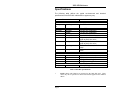
Specifications
The following table defines the typical environmental and electrical
specifications of the EXP-MX. Individual drive types may vary.
Characteristic
Environmental
Temperatur operating
e
storage
Humidity
operating
storage
Altitude
operating
storage
Vibration *
operating
storage
Shock *
operating
storage
Electrical
Power
Current
Other
Weight
Value
5 to 50°C ambient
-40 to 65°C
8 to 85% non condensing
5 to 95% non condensing
0 to 10,000 ft (3,000 m)
0 to 40,000 ft (12,000 m)
1 G (max) acceleration, 5-500 Hz
(peak to peak) sine wave
2 G (max) acceleration, 5-500 Hz
(peak to peak) sine wave
10 G, 11 ms duration, half-sine shock
pulse
70 G, 11 ms duration, half-sine shock
pulse
maximum
typical
maximum
typical
20 W for 15 seconds at power-up
10 W
+5V @ 1.5A, +12V @ 1A
+5V @ 1A, +12V @ 0.4A
maximum
35 oz (1000 g), over all models
Table 1. EXP-MX Specifications.
*
Page 2
NOTE: Shock and Vibration as measured on the hard disk itself. These
values may not be equivalent to shock and vibration applied to the VMEbus
chassis.
2. Installation
Before installing the EXP-MX, unpack and inspect it for shipping damage.
DO NOT REMOVE THE MODULE FROM ITS ANTI-STATIC BAG UNLESS
YOU ARE IN A STATIC-FREE ENVIRONMENT.
THE EXP-MX, LIKE
MOST OTHER ELECTRONIC DEVICES, IS SUSCEPTIBLE TO ESD
DAMAGE. ESD DAMAGE IS NOT ALWAYS IMMEDIATELY OBVIOUS, IN
THAT IT CAN CAUSE A PARTIAL BREAKDOWN IN SEMICONDUCTOR
DEVICES THAT MIGHT NOT IMMEDIATELY RESULT IN A FAILURE.
ENSURE THAT THE INSTALLATION PROCESS AS DESCRIBED HEREIN
IS ALSO PERFORMED IN A STATIC-FREE ENVIRONMENT.
Installing the EXP-MX
Prior to insertion of the EXP-MX, the EXM expansion subplane must be installed;
follow the instructions in the EPC manual to do so.
The EXP-MX is always inserted as the right-most module (assuming vertically
oriented modules). Insert it so that its rear connector mates with the lower rightmost
connector of the subplane. Tighten the top and bottom front-panel screws to hold it
firmly in place.
HANDLE THE DISK MODULE WITH CARE, AVOIDING SUDDEN DROPS
AND JOLTS.
INSERT IT WITH ADEQUATE CONTINUOUS FORCE
RATHER THAN TAPPING OR HAMMERING ON IT.
MAKE SURE THAT POWER TO YOUR VME SYSTEM IS OFF. INSERTING
OR REMOVING THE DISK MODULE IN A LIVE BACKPLANE WILL
DAMAGE THE MODULE.
WHEN INSERTING THE MODULE, AVOID TOUCHING THE CIRCUIT
BOARD AND CONNECTOR PINS, AND MAKE SURE THE ENVIRONMENT
IS STATIC-FREE.
Page 3
EXP-MX Reference
Configuration
There are two aspects to configuring a hard disk in a PC/AT-compatible system. The
first is setting up the correct parameters in the CPU BIOS. The second is actually
partitioning and formatting the hard disk with the operating system. EPC systems
shipped with software loaded have both the BIOS and the hard disks pre-configured
at the factory. In these cases this configuration section can be skipped in its entirety,
as the products can be plugged into the subplane and powered up with no user
configuration required.
The EPC BIOS
The BIOS in the EPC to which the EXP-MX is attached needs to be configured for
the number of floppy and hard disk drives, and for their type. For hard disks, the type
identifies the basic hard disk parameters: the number of cylinders, heads, and sectors
in the hard disk assembly. Invoke the BIOS setup function by pressing the CTRLALT-ESC keys simultaneously.
Floppy Disk Drive
Diskette drive A should be defined as 1.4 MB, 3.5 inch, unless the jumper is removed
as described in the section Adding an External Floppy Drive, page 7 and an external
drive is connected as the A: drive. In this case drive A: needs to be defined with the
characteristics of the external drive. Drive B: should be set to NONE unless an
external B: floppy drive is installed, in which case it needs to be defined with the
characteristics of the external drive.
Fixed Disk Menu
Press F3 to bring up the fixed disk menu.
EXP-MX series
Set the BIOS definition of drive C: to AT. A line then displays which lets you select
the drive type. Each EXP-MX drive is labeled with the drive type and/or parameters
for use during this step.
Some of the newer, high-capacity drives may not appear in the BIOS list. In this case,
most BIOS versions include user-editable drive types (type 48 and 49) that allow you
to manually enter the drive's parameters.
Page 4
Installation
If a user-editable drive does not have a label or the label is no longer readable, but
you know the model number, refer to the table below.
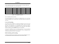
Drive
MX100
MX200 & MX200A
MX500
MX1000 (Award BIOS)
MX1000 (Phoenix BIOS)
Cylinders
814
723
1017
1024
2100
Heads
9
13
16
16
16
Sectors
32
51
63
63
63
Capacity
115 MB
235 MB
501 MB
528 MB
1084 MB
Table 2. User-Editable Parameters.
Drive D: should be defined as NONE.
Note that EXP-MX1000 drives will appear as 528 MB hard drives to a system using
an older Award BIOS. Newer systems that use the Phoenix BIOS will recognize the
entire drive.
Low-level Formatting
Only older-generation hard disks ever needed to be formatted at a low level to set the
interleave, map out bad sectors, or to clear the disk of all data. Disks were typically
delivered by the manufacturer in an unformatted state. All disk drives used by
RadiSys are pre-formatted by the manufacturer. These modern disks, with automatic
bad-block mapping, typically NEVER need low-level formatting.
No function is provided for low-level formatting IDE drives. Several commercial
programs are available that perform a low-level format. However, RadiSys does not
recommend any particular software for this purpose.
Disk Partitioning and Formatting
Configuring the BIOS for the hard disk is the first part of the configuration process.
Next, the disk must be partitioned and formatted for the operating system.
Page 5
EXP-MX Reference
Partitioning is the process of building the primary data structures on the hard disk
which define the physical characteristics of the drive and divide the disk into one or
more sections. Formatting (also called high-level formatting) is the process of
actually building a file system on a disk drive partition - basically setting up each
partition so that it can store the files and directory structure required.
Depending on the context in which you ordered the EXP-MX, the hard disk could be
one of the following:
1.
A bootable disk with DOS and other software pre-installed in a ready-to-run
fashion. In this case the system is ready to use, and no further action is
required.
2.
An empty disk, with no partitioning. In this case, partitioning and formatting
must be done before the disk can be used.
Partitioning and Formatting for MS-DOS
The process for MS-DOS 5.0 is described here. Other operating systems have similar
procedures, with different details.
1) Boot the system using the operating system SETUP diskette.
2) You are asked several questions. Follow the instructions on the screen until you
see the following prompt:
Allocate all free hard disk space for MS-DOS
Allocate some free hard disk space for MS-DOS
Do not allocate free hard disk space for MS-DOS
The first option is highlighted. Allocate ALL the hard disk space by pressing
ENTER. MS-DOS automatically partitions and formats the drive and loads the
operating system.
The remainder of the partitioning and formatting process is automatic. Follow the
instructions on the screen.
Page 6
Installation
A DISK PARTITIONED, FORMATTED, AND LOADED AS ONE TYPE WILL
PROBABLY NOT BE RECOGNIZED BY A CPU SET TO A DIFFERENT DRIVE
TYPE. CHANGING THE DRIVE TYPE OF THE DISK LATER USUALLY REQUIRES
COMPLETE RE-PARTITIONING AND RE-FORMATTING WITH LOSS OF ALL
DATA ON THE DRIVE.
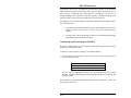
Adding an External Floppy Drive
An external floppy drive can be used with the EXP-MX via cable attachment to the
34-pin connector. Most standard 5.25" and 3.5" drives can be used. The EXP-MX
does not support drives that take their 5V power from the ribbon cable.
The 34-pin front-panel connector is defined in the following table. All odd-numbered
pins are connected to Ground.
Pin
2
4
6
8
10
12
14
16
Signal
-DENS
not used
not used
-IDX
-MO1
-DS2
-DS1
-MO2
Pin
18
20
22
24
26
28
30
32
34
Signal
-DIRC
-STEP
-WD
-WE
-TRQ0
-WP
-RDD
-HS
-DCH
34
2
1
Table 3. Floppy Cable Pin-Out.
Assuming the drive is to be configured as the B: drive on a straight (pin-1 to pin-1,
etc.) cable, configure the floppy drive as follows:
•
Set the DS (drive-select) jumper or switch to 2. (If numbering on the drive
starts at 0 instead of 1, set it to 1.)
•
For 5.25" drives, if the drive has an MM/MS (motor-control) jumper or
switch, set it to MS (motor control derived from drive-select signal).
Page 7
EXP-MX Reference
•
For 5.25" drives, if the drive has a SR/DC (disk change) jumper or switch,
set it to DC.
An application note is available from RadiSys Technical Support that describes the
process of configuring an external floppy drive in more detail.
If the internal floppy drive is enabled, it is always configured as the A: drive. If you
wish to add an external drive and it needs to be the A: drive, two actions must be
taken:
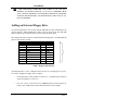
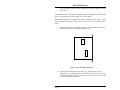
1) Remove jumper JP2 (see diagram below) on the EXP-MX circuit board.
This disables operation of the internal floppy drive.
JP2
JP1
Figure 1. J1 & J2 Jumper Location.
2) Connect the drive through a "twist cable" (i.e., connect drive pin 10 to
EXP-MX pin 16, and drive pin 12 to EXP-MX pin 14). If you are using a
straight ribbon cable, configure the drive DS as 1 instead of 2 (or 0 instead
of 1 if the numbering starts at 0).
Page 8
Installation
Additional Considerations
It is possible that data corruption can occur on a floppy diskette in the external floppy
drive when the power is turned off, because the controller chip asserts the WRITE
ENABLE bit. To prevent this, do one of the following:
1. Remove the floppy diskette from the external floppy drive before powering off
the system.
2. Turn off the power to the external floppy drive before powering off the system.
Troubleshooting
Internal Floppy Drive Problems
If you cannot boot from or access the internal floppy disk drive, the problem could be
any one of the following:
(1) the software configuration
(2) the drive configuration
(3) power to the EXP-MX
(4) the drive-enable jumper
(5) an improperly formatted diskette
(6) the EXP-MX.
To isolate the problem, perform the following operations:
A. Invoke the BIOS setup program
B. Ensure that drive A is specified as a 1.44 MB 3.5" drive.
C. Ensure that the drive-enable jumper (JP2) on the circuit board in the
EXP-MX is installed.
Page 9
EXP-MX Reference
D. Ensure that the LEDs indicating +5V and +12V power to the EXP-MX are
lit.
E. Ensure that you don't have another module in the system (e.g., EXM or PC
card) whose I/O ports or interrupt and DMA usage conflict with those of the
EXP-MX. Refer to Chapter 3, Programming Interface, for the
EXP-MX requirements.
F. Ensure that the trouble isn't with the diskette by attempting to read it or boot
with it on another system.
Internal Hard Drive Problems
If you cannot boot from or access the hard disk, the solutions listed below may apply.
A. Invoke the BIOS setup program and ensure that you have the correct fixeddisk type selected (see table in previous section).
B. Check the voltage LEDs to see if the drive has power. Check the cable
connections and the cable itself for damage, bent pins, etc.
C. Use Microsoft Diagnostics (MSD.EXE) to check for devices that may
conflict with the EXP-MX IRQ (e.g., an EXM-3, EXM-9, or EXM-MX).
D. Ensure that the device has been formatted as a system disk and that the
partition is active (which will require booting from a floppy).
External Floppy Drive Problems
If you have trouble with an external floppy drive, review the previous section on
connecting an external floppy drive to ensure that the drive is configured correctly.
A. Ensure that you are supplying power to the drive.
connections and the cable itself.
Check the cable
B. If you want the external drive to be A:, make sure that you've twisted the
cable as described earlier, that the drive enable jumper on the circuit board
has been removed (to disable the internal drive), and that the selection for
drive A: on the BIOS setup screen matches the characteristics of your external drive.
Page 10
Installation
C. If you want the external drive to be B:, ensure that the selection for drive B:
on the BIOS setup screen matches the characteristics of your external drive.
D. Ensure that your diskette is readable or bootable on another system.
Common Error Messages
Some error messages that might appear and their interpretations are:
Disk boot failure. No boot disk could be found. Boot from a floppy and check to
see that the hard disk is accessible, the partition is active, and the hidden system files
are present.
Diskette drives or types mismatch error. The BIOS setup information is
inconsistent with the floppy drives detected (or absent). Run the BIOS SETUP
program and correct the inconsistencies.
Floppy disk controller error. The BIOS could not find the floppy disk controller in
the EXP-MX (e.g., unit is not installed, another device is using conflicting I/O
addresses).
General failure... Usually indicates an unformatted disk or diskette.
Non-system disk. Trying to boot from a disk or diskette that is not formatted as a
bootable system disk.
Page 11
EXP-MX Reference
NOTES
Page 12
EXP-MX Reference
Address
Description
Notes:
1F0
Data Register (16 bits)
MX only
1F1
Error / Write Precompensation Register
MX only
1F2
Sector Count Register
MX only
1F3
Sector Number Register
MX only
1F4
Cylinder Low Register
MX only
1F5
Cylinder High Register
MX only
1F6
SDH Register
MX only
1F7
Status / Command Register
MX only
2B0
not available
2B1
not available
2B2
not available
2B3
not available
2B4
not available
2B5
not available
2B6
not available
2B7
not available
3F2
Floppy Operations Register
3F4
Floppy Command Register
3F5
Floppy Data Register
3F6
Alternate Status / Digital Output Register
MX only
3F7
Drive Address Register / Floppy Control Register
MX only
Table 4. EXP-MX I/O Port Addresses.
Page 14
4. Support and Service
In North America
Technical Support
RadiSys maintains a technical support phone line at the telephone number listed on
the cover of this manual that is staffed weekdays (except holidays) between 8 AM
and 5 PM Pacific time. If you have a problem outside these hours, you can leave a
message on voice-mail using the same phone number. You can also request help via
electronic mail or by FAX addressed to RadiSys Technical Support. The RadiSys
FAX number is also listed on the cover of this manaul. The RadiSys E-mail address
on Internet is [email protected]. If you are sending E-mail or a FAX, please
include information about both the hardware and software in use, and provide a
detailed description of the problem (specifically, describe how the problem can be
reproduced). We will respond by E-mail, phone or FAX by the next business day.
Technical Support Services are designed for customers who have purchased their
products from RadiSys or a sales representative. If your RadiSys product is part of a
piece of OEM equipment, or was integrated by someone else as part of a system,
support will be better provided by the OEM or system vendor that did the integration
and understands the final product and environment.
Web Site
RadiSys maintains an active site on the World Wide Web. The home page URL is
http://www.radisys.com. The site contains current information about the company and
locations of sales offices, new and existing products, contacts for sales, service, and
technical support information. Fact sheets, manuals, and software can also be
downloaded from the Web site, and you can also send e-mail to RadiSys Technical
Support. Requests for sales, service, and technical support information receive
prompt response.
Page 15
EXP-MX Reference
Repair Services
Factory Repair Service is provided for all RadiSys products. Standard service for all
RadiSys products covers factory repair with customers paying shipping to the factory
and RadiSys paying for return shipment. Overnight return shipment is available at
customer expense. Normal turn-around time for repair and re-certification is five
working days.
Quick Exchange services (immediate shipment of a loaner unit while the failed
product is being repaired) or other extra-cost services can be arranged, but need to be
negotiated in advance to allow RadiSys to pool the correct product configurations.
RadiSys does not maintain a general "loaner" pool: units are available only for
customers that have negotiated this service in advance.
RadiSys does not provide a fixed-price "swap-out" repair service, as customers have
indicated that issues of serial number tracking and version control make it more
convenient to receive their original products back after repair.
Warranty Repairs
Products under warranty (see warranty information in the front of this manual) will
have manufacturing defects repaired at no charge. Products sent in for warranty
repair that have no faults will be subject to a recertification charge. Extended
Warranties are available and can be purchased at a standard price for any product
still under warranty. RadiSys will gladly quote prices for Extended Warranties on
products whose warranties have lapsed; contact the factory if this applies.
Customer induced damage (resulting from misuse, abuse, or exceeding the product
specifications) is not covered by the standard product warranty.
Non-Warranty Services
There are several classes of non-warranty service. These include repair of customer
induced problems, repairs of failures for products outside the warranty period,
recertification (functional testing) of a product either in or out of warranty, and
procurement of spare parts.
All non-warranty repairs are subject to service charges. RadiSys has determined that
pricing repairs based on time and materials is more cost-effective for the customer
than a flat-rate repair charge. When product is received, it will be analyzed and, if
appropriate, a cost estimate will be communicated to the customer for authorization.
Page 16
Support and Service
After the customer authorizes the repair and billing arrangements have been made,
the product will be repaired and returned to the customer.
A recertification service is provided for products either in or out of warranty. This
service will verify correct operation of a product by inspection and testing of the
product with standard manufacturing tests. There is a product-dependent charge for
recertification.
There are only a few components that are generally considered field-repairable, but,
because RadiSys understands that some customers want or need the option of
repairing their own equipment, all components are available in a spares program.
There is a minimum billing charge associated with this program.
Arranging Service
To schedule service for a product, please call RadiSys Technical Support directly at
the telephone number listed on the cover of this manual. Have the product model and
serial numbers available, along with a description of the problem. A Technical
Support representative will issue a Returned Materials Authorization (RMA) number,
a code number by which we track the product while it is being processed. Once you
have received the RMA number, follow the instructions of the Technical Support
representative and return the product to us, freight prepaid, with the RMA number
clearly marked on the exterior of the package.
If possible re-use the original
shipping containers and packaging. In any case, be sure you follow good ESDcontrol practices when handling the product, and ensure that anti-static bags and
packing materials with adequate padding and shock-absorbing properties are used.
Ship the product, freight prepaid, to the address listed on the cover of this manual
When shipping the product, include the following information: return address,
contact names and phone numbers in purchasing and engineering, and a description
of the suspected problem. Any ancillary information that might be helpful with the
debugging process will be appreciated.
Page 17
EXP-MX Reference
Other Countries
Contact the sales organization from which you purchased your RadiSys product for
service and support.
Spare Parts List
There are only two field replacable parts on the EXP-MX: the floppy drive and the
hard disk. A list of the replacable drives is found in the table below:
Floppy Drive
40 MByte SCSI hard disk
40 MByte IDE hard disk
100 MByte IDE hard disk
200 MByte IDE hard disk
500 MByte IDE hard disk
For use with all EXP-MX
modules
For use with the EXP-MS40
For use with the EXP-MX40
For use with the EXP-MX100
For use with the EXP-MX200
& MX200A
For use with the EXP-MX500
Table 5. Spare Parts List.
Page 18
85-0017
85-0050
85-0055
85-0051
85-0041
85-0053