1
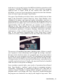
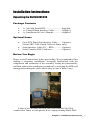
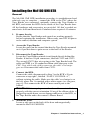
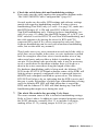
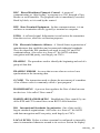
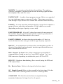
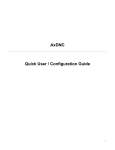
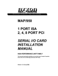
Mx1100 UMI Serial BTR Installation & User’s Manual For Fanuc Tape Readers Copyright © 2012 All rights reserved. Nexas Networks Inc. 627 Main Street East, Suite L09 Hamilton, Ontario Canada L8M 1J5 www.nexasnet.com Mx1100 UMI Serial Fanuc BTR Table of Contents Introduction............................................................................VII About This Manual............................................................VII History of the BTR............................................................VII Installation Instructions......................................................... 1 Package Contents........................................................…...1 Installing the Mx1100 UMI BTR...................................... 2 Operating The BTR........................................................... 5 Layout Diagram of the Mx1100 UMI Serial BTR............ 6 Reference................................................................................. 7 General Troubleshooting................................................... 7 Nexas Technical Support & Service............................. 11 User’s Notes.................................................................... 12 Glossary................................................................................. 13 Appendix A: Configuration & Settings………………….. 17 DNC Software Configuration Information...................... 17 Mx1100 Option Jumper Settings..................................... 17 Mx1100 Serial Port Pin Configuration............................ 18 Serial Data Cable Configurations.................................... 18 Appendix B: ASCII Code Reference Table........................ 19 Contents _III Contents _IV Introduction Thank you for purchasing the Mx1100 UMI (Universal Machine Interface) BTR. At Nexas we invest substantial effort in the design, manufacture and testing of each unit we build, and back it with a three-year limited warranty. We are confident you will find the Mx1100 an important component of your shop floor communications system. About this Manual This manual explains how to install and operate the Mx1100, and consists of the following sections: explains how to install the Mx1100 UMI BTR interface board. Installation Instructions contains a troubleshooting section, notes area and contact information for customer service and technical support. Reference A, Configuration & Settings provides information for software (DNC) configuration, BTR jumper settings and serial cable configuration (“pin-out”) charts. Appendix lists ASCII values in both Decimal and Hex formats, their corresponding symbol, and keyboard key where applicable. This may be helpful in configuring DNC software in some cases. Appendix B, ASCII Table The History of the BTR The “Behind the Tape Reader” board, or BTR as it is commonly called, is an electronic signal processor designed to emulate the function of a paper Tape Reader and provide an RS232 serial port as an alternate method of data entry to an NC or CNC control. RS232 is an international standard for electronic communications, and is a faster and more reliable means of data input than using punch tape or Manual Data Input (MDI). Originally, the only one way that a part program (the “G-code”) could be entered into a machine tool was through MDI mode, which allowed the program to be input using a keypad at the control. The MDI process was fine for small programs, but it was time consuming and error prone for longer programs. It Introduction_ V took time to set up and to prove the MDI code before operation could commence. Machine flexibility was low, since each new program required time to input. With all the wasted time and lack of flexibility, it was not very long before someone invented an alternate form of control input, the paper Tape Reader. The paper Tape Reader provided a faster, more reliable form of data input to the numerical control. However, these Tape Readers were mechanical in nature, and required regular maintenance and care to perform properly. Tape Readers allowed data and programs that were punched out on a paper tape to be read in by the control at a rate of approximately 300 to 400 characters per second. A few problems inherent in the Tape Reader are: it has limited ability to accept commands and inform the operator of problems and status; it is prone to mechanical problems; it requires cleaning, lubrication and other maintenance; it has a limited capacity of 1000 feet (305 metres) of tape. It was commonly suggested that a busy shop keep a spare reader in inventory in preparation for the time when one broke down. The process of punching data tapes (whether paper, Mylar or metal) was expensive, time-consuming and brought up storage concerns. Because of the absolute nature of a punched tape, the process had to be redone for every program revision. The programmer and operator had to work closely together to keep the tape accurate and up to date. Old tapes had to be filed or destroyed and the latest version had to be carefully marked and stored. Finally, the tape itself had to be handled with care since it was prone to damage. Later machine controls had a new mode of operation that allowed their Tape Reader’s “endless” spool of tape to surmount memory constraints. Originating on Numerical Controls (NC) that had no memory, Direct Numeric Control (DNC) allowed execution of a program while it was being read. This “drip-feed” method meant that the program was limited in size only by the length of tape used. This Introduction_ VI type of operation was very much appreciated later on with the advent of Computerized Numeric Controls (CNC). With true onboard memory the CNC had much greater capabilities and inevitably programs got longer and the need for more memory grew. With control memory being expensive and limited, DNC has remained the only way some modern manufacturers can operate. Tape Readers are still commonplace on modern controls today. However, thanks to serial DNC capabilities, many shops use Tape Readers for backup purposes only. The modern equivalent of a Tape Reader is the BTR interface board, which emulates paper Tape Readers. The Mx1100 UMI BTR is a microcontroller-based interface board that allows communications with a machine control for the purposes of loading programs into memory or running DNC. BTRs generally connect to a computer and permit a programmer to send a complete, formatted program to the machine control. The machine then loads the program as if from tape, either to memory for later execution, or for immediate blockby-block execution (DNC). Because the Mx1100 UMI BTR emulates the Tape Reader, the control really has no way of knowing that the source of the program is a computer port instead of a tape. The Mx1100 UMI BTR eliminates punching of tape, has no moving parts, can handle transfer speeds that exceed that of a Tape Reader, uses the programmed (source) file, is less expensive than a Tape Reader, allows the Tape Reader to still be used, supports the use of the control’s punch capability, and does not require maintenance. It’s no wonder that the BTR, in combination with DNC software, has become the preferred alternative to using the Tape Reader and (in many cases) to upgrading CNC memory. While the Nexas BTR gives the machine control the ability to receive programs from a PC, it has nothing to do with the specifics of what is being sent to the control. DNC software, or at the very least some form of serial communications software, is responsible for transmitting the data to the control, and the control expects that data to be in a specific format. The part program must be formatted just as it would be for punching to tape, and the DNC software must be configured to send it as if it were a tape. The BTR acts only as a gateway or port to the control. The required program format is usually described in the control’s Operations Manual. Please consult the manual for information on how to configure the part code programs for the control. Introduction_ VII Installation Instructions Unpacking the Mx1100 UMI BTR Package Contents 1 x Mx1100 Serial BTR..............................Supplied 1 x Fanuc Ribbon Interface Cable.............. Supplied 1 x Installation & User’s Manual................ Supplied Optional Items Facit 4070 Punch Port Interface Cable....… Optional (Nexas SKU-5100: Punch Cable for Fanuc only) Serial Interface Cable (PC – BTR).............. Optional Serial Transfer (DNC) Software…….......... Optional Before You Begin Please read all instructions before proceeding. We recommended first making a temporary installation, becoming familiarized with the components and orientation of the assembly, testing the functionality, and then making the installation permanent by mounting the BTR and routing and securing the cables where they are out of harm’s way. A shot of our old Mx1000 BTR (now built into the Mx1100) connected to Fanuc 6 (with punch) & to a laptop running Multi-DNC. Chapter 1: Installation Instructions _ 1 Installing the Mx1100 UMI BTR General The Mx1100 UMI BTR installation procedure is straightforward and relatively easy to complete – connect the BTR to the CNC where the Tape Reader was connected, optionally connect the Tape Reader to the BTR, and mount the BTR on the inside of the Tape Reader door. All the hardware and accessories are provided. All that’s needed are some basic skills and hand tools. Estimated time required: 45 minutes. 1. Prepare the site. Ensure that the Tape Reader and control are working properly before beginning the installation. When ready, turn OFF all power to the control, machine and computer system. 2. Access the Tape Reader. Locate the panel on the control that has the Tape Reader mounted on it. Open this door to gain access to the back of the Reader. 3. Disconnect the Tape Reader. Locate the Tape Reader printed circuit board directly behind the Reader. It has two 50-pin connectors, labelled CNT1 and CNT2. The second (CNT2) has wires going to the Tape Reader head. The cable on CNT1 is a 50-conductor ribbon cable that goes to the CNC. Note which side of this connector the cable’s red stripe goes on. Disconnect this cable from CNT1. 4. Connect the BTR. Connect the cable disconnected in Step 3 to the BTR’s 50-pin connector at top right*, labelled “FANUC CONTROL A”, without twisting the cable. Make sure the cable’s red stripe is on the left, where Pin 1 is marked with a white square (see diagram, page 6). This connects the BTR’s Fanuc control port to the control. Caution: It is very important that the cables are installed properly with the correct orientation. If one of the ribbon cables is plugged in upside down, severe damage will occur to the BTR, to the Tape Reader and to the control’s Master Board. 5. Mount the BTR. Locate a safe spot on the back of the door and magnetically mount the Mx1100 UMI BTR. Chapter 1: Installation Instructions _ 2 6. Option: Connect the Tape Reader to the BTR. If you wish to enable the paper Tape Reader, take the new 50conductor ribbon cable and plug it onto the JP5 connector (labelled “FANUC TAPE READER A”) at the bottom right of the BTR.* The red side of the cable goes on pin 1 of the connector (see diagram, page 6). Plug the other end of the cable onto the CNT1 connector on the Fanuc Tape Reader board, from which the cable was removed in Step 3 – ensuring the red wire on the ribbon cable goes on pin 1 of the connector, as noted in Step 3. 7. Option: Punch Cable. If you would like to punch part programs, parameters, etc. from the control to the computer, and you have purchased the optional Fanuc Facit 4070 Punch Cable, connect the control’s punch port to the BTR. Locate the punch port on the control. It’s usually a blue rectangular 20-pin (Honda) connector. Plug the Punch Cable into this port. Plug the 26-pin end onto the BTR’s JP4 connector, labelled “PUNCH IN”. The red stripe goes on the side with Pin 1 (see diagram on page 6). Remove the JP17 jumper (labelled “PUNCH DISABLE”) in the upper right corner of the BTR. 8. Configure the BTR. Set the jumpers on the BTR to configure the communications parameters required for your DNC system. The option jumpers, listed on page 17, include the following: Jumper A1 and A2 set the Baud rate. Typically 9600 baud (both jumpers ON) is used unless your cable doesn’t support that rate reliably. The RS232 specification supports 9600 Baud (Even parity, 7 data bits and 1 stop bit) with a cable length up to 50 feet (15 metres), but it is often possible to exceed that. It’s important to use cable specifically designed for RS232 serial data, 22 AWG, twisted pair, stranded wire (not solid), shielded, low capacitance (a rating of 11 to 15 pF per foot) is best. If you have a long cable run or are have unreliable data transmission, try lowering the Baud rate. Note: In our opinion, CAT3 or CAT5 UTP Ethernet cable is not suitable for reliable machine tool serial communications. Use shielded stranded AWG 22-24 serial cable. Chapter 1: Installation Instructions _ 3 Jumper A3 OFF adds hardware (RTS/CTS) handshaking. A3 ON is software (Xon/Xoff) only. Generally it is preferable to use both, which means setting A3 OFF and making sure your cable supports hardware handshaking (see Note 6 on p 9). Jumper A4 OFF uses the standard Xoff character, $13 Hex. Set A4 ON if your terminal software uses $93 Hex for Xoff. Jumper A5 OFF uses the standard Xon/Xoff handshaking method (a Single Xoff). Setting A5 ON sends a continuous stream of Xoff back to the computer until the next Xon. This enables the BTR to be used with some terminal programs that were intended for use with a modem, such as PROCOMM ™ although we recommend the use of proper DNC software. Jumper A6 OFF will echo incoming data back to the PC for diagnostic purposes. On reset, the software version is outputted for instance. Set A6 ON for normal use. Jumper A7 OFF is ISO data, and ON converts incoming ISO data to EIA format for controls that require EIA data. Jumper A8 overrides the Tape Reader’s selection of BTR or Tape mode. If the Tape Reader wasn’t reconnected to the BTR, or if the Tape Reader isn’t intended to be used often and the BTR will usually in Tape mode, set A8 ON. (Remember to remove it when a tape needs to be read.) __________________________________________________ SG JMPR OFF = COM1 Signal Ground surge suppression. PWR P9 DBL ON activates power output on COM1’s pin 9, for use with devices such as buffers (see note on page 18). Punch Disable – if you are not using a Facit 4070 punch port (SKU-5100 cable), keep this jumper ON. 9. Connect to the Computer. Connect a serial cable from the 9-pin COM1 on the BTR to the computer’s serial port (see page 18 for cable configurations). 10. Test the Functionality. Refer to “Operating the Mx1100 UMI BTR” (page 5), and if necessary, “Reference” (page 7). Chapter 2: Operating the Mx1100 _ 4 Operating the Mx1100 UMI BTR To use the control’s new serial port: Make sure the cables are connected correctly and prepare your DNC software. Press Reset on the Fanuc control to reset the BTR and ensure that no residual data is present in its input buffer. If BTR option jumper A8 is OFF (switch enabled), and the Tape Reader is connected, switch the BTR into BTR mode either by turning off the Tape Reader or by switching the Tape Reader to Release mode. Start an upload to the control from your DNC software, and then load a program at the control as if from tape. You can put the control in Tape mode and press READ or INPUT to load the program into memory (if it will fit), or put the control in DNC (or External) mode and press Cycle Start to run it in DNC mode – also known as “drip feeding”. (These mode names and key names will vary according to the control model.) If you have any difficulty or concerns, please refer to “General Troubleshooting” on page 7. Helpful hints Adding a couple of Carriage Returns to the end of the file will ensure that the entire file is transmitted. Some combinations of DNC software and CNC control sometimes miss the end of a file, so it’s a good idea to provide some harmless extra characters as a buffer. The BTR responds to the Break character by resetting and clearing its buffer. The Break character is ASCII value 3, or HEX 03 (see Appendix B, page 19). If your DNC software can be configured to send control codes, it’s a good idea to have it send a Break character at the beginning of every g-code program it sends. This will guarantee that the BTR buffer is reset and ready for a new program each time, regardless of whether the CNC didn’t properly finish reading the previous one. (The Break character will not be passed through to the CNC, and the start of the program following it will wait while the BTR is resetting.) Chapter 2: Operating the Mx1100 _ 5 Layout of the Mx1100 UMI Serial BTR Chapter 2: Operating the Mx1100 _ 6 1 A1 A2 A3 A4 A5 A6 A7 A8 LOAD RESET (C)2003 S/N: 0303011 JP10 REG ENBL COM2 Status LEDs Status Power COM1 1 MEMEX ELECTRONICS INC. PWR P9 DBL MEMEX ETHERNET MODULE 24 Volt regulator +24TR and REG ENBL must be OFF; If +5TR is OFF, then both +24TR and REG ENBL must be ON. (See Note 1 on Page 7.) JP4, PUNCH IN 26-pin header - Connect to CNC's punch port JP10, REG ENBL J7 SG JMPR JP22 I M PO RT ANT: If +5TR is ON, then both J7, Power Terminal Disables Signal Ground Surge Suppression on COM1 JP22, SG JMPR 24 Volt selector JP16, +24TR Mode Switch Connector SP1 Configuration Jumpers A1-A8 Connect to Computer COM1 +7-24V COM 1 JP16 -GND +24TR Enable power output on COM1 pin 9 JP33, PWR P9 DBL SP1 JP3 +5V Reset PWR ON STATUS TX RX RTS CTS TX RX RTS CTS 1 1 JP6 1 1 1 50-pin header - Connect to Tape Reader (Optional) JP5, FANUC Tape Reader A FANUC TAPE READER A Pin 1 indicator: Cable's red stripe always goes on whichever side has this mark JP5 JP17 PUNCH DISABLE UNIVERSAL MACHINE INTERFACE TAPE READER B JP7 JP8 MX1100 R3 MADE IN CANADA WWW.MEMEX.CA FANUC CONTROL A CONTROL B 50-pin header - Connect to CNC JP8, FANUC CONTROL A Pin 1 indicator: Cable's red stripe always goes on whichever side has this mark JP4 PUNCH IN JP13 TAPE IN be OFF; If punch cable is not connected, JP17 must be ON. JP18 IMPORTANT: If punch cable is connected, JP17 must +5TR 5 Volt selector JP18, +5TR If cable has no key, be extra careful orienting the cable Cable keyway. JP17 Punch Disable Reference This chapter contains troubleshooting hints and information about Nexas Technical Support and Service. General Troubleshooting The Mx1100 UMI BTR is designed to install easily and quickly. However, if experiencing difficulty in the procedures, please check the following to isolate and resolve the problem: 1. Check that the “PWR ON” LED on the BTR (leftmost LED in the LED block at bottom centre*) is on and bright. The RTS LED for COM1 should also be on. If there is no power to the BTR, ensure that the cables from the Control (and from the Tape Reader if connected) are oriented properly and are well secured. Also, check that one of the following is true: a) The “+5TR” jumper (JP18 at bottom right) is ON and the “+24TR” jumper (JP16 at middle left) and “REG ENBL” (JP10 near middle bottom) are OFF; -orb) The “+5TR” jumper (JP18) is OFF and the “+24TR” jumper (JP16) and “REG ENBL” (JP10) are ON In case “a” above, the BTR is sourcing 5 volts from the CNC; in case “b” it is sourcing 24 volts and reducing it to 5 volts. Typically 5V (setting “a”) is used with a Fanuc control. Note: The default power source setting is “a” above, 5 volts. However, in some CNCs the 5-volt supply has faded to below the threshold that will power the BTR. If the BTR won’t power on, try using 24 volts by setting the jumpers as in “b” above. Note: * All references made to objects located on the BTR are made with respect to the BTR being oriented horizontally so that the “Universal Machine Interface” label can be read at the bottom right. See diagram, page 6. Chapter 3 – Reference 7 2. Alternate source of power. If the PWR LED still does not come on, carefully find a source of power on the control between 7 and 24VDC and wire it in to screw-down terminal block J7 at the lower left corner of the BTR. When power is brought in through the terminal block, the jumpers must be set as in “b” above. 3. Check that the BTR is working properly. When the control is powered up or reset, the BTR’s STATUS LED (2nd LED in LED block at middle bottom) should blink. One blink indicates that the Mx1100 is in BTR Mode. This means that it is ready to receive information through the serial port and to send it to the control. Two blinks indicate that the Mx1100 is in TAPE Mode. This means that it is ready to pass information through the BTR from the Tape Reader to the Control. (The leftmost TX LED will also blink, as the BTR sends out a status message on its COM1 port during power up.) With most Tape Readers, turning the Tape Reader on/off or switching it between Load and Release will switch the BTR between modes. 4. Check the status message. When the BTR is powered on or reset, it sends a short message on its COM1 port, indicating which mode it’s in. The STATUS and first TX LEDs will blink during output. If the computer is properly connected, and your DNC software is configured to match the BTR communication settings and is set to receive a file, it should be possible to capture and read the status message. If the message is clearly readable then the BTR’s communications are good, and so is the cable, the settings, the computer and the DNC software. 5. The Status and Tx LEDs flash but there is no status message. First the computer has to be watching for the status message with DNC software, or at least with a terminal program or utility. After installing your software, verify that the correct communication parameters are set and check that the correct computer COM port is being used. Check that the BAUD RATE is properly set and matches the baud rate on the BTR (check option jumpers A1 and A2 – see pg. 17) and that the STOP BITS are set to 1. Make sure that the cable connecting the BTR to the computer is a properly configured RS-232 serial data cable and that it is properly connected (see Step 6 below). Also verify that the PC’s COM port is functioning properly. Chapter 3 – Reference 8 6. Check the serial data cable and handshaking settings. First, make sure the cable matches the appropriate diagram under “Mx1100 UMI BTR Cable Configurations” (page 18). Second, make sure the cable, BTR settings and software settings match with regard to handshaking method. If using software handshaking (Xon/Xoff) only (see table A on page 18), make sure that BTR Jumper A3 is ON and your DNC software is set for Xon/Xoff handshaking only. If using hardware handshaking (see table B on page 18), make sure that BTR Jumper A3 is OFF, your DNC software is set for RTS/CTS and Xon/Xoff handshaking, and the cable supports it by having the wires for RTS and CTS connected for a total of five wires connected at each end. (Note: Software handshaking can be used with a hardware handshaking cable, but not the other way around.) Third, make sure every wire connection at each end of the cable is solid, there are no breaks in the wires, no wire insulation is pulled back far enough to allow bare wire to touch another wire or any other metal parts, and no solder or debris is touching more than one pin. If everything looks good at the ends, it may be necessary to use a multi-meter to determine whether there is a break or a short in the wires somewhere along the length of the cable. If a hardware handshaking cable is being used, the leftmost CTS LED (in the STATUS LED bank at bottom centre of the BTR) will light up when a properly configured cable is connected between the BTR and a computer and both are powered on. The leftmost RTS LED will always be on, indicating that the BTR is active and the port is ready. Regardless of which type of handshaking is being used, the leftmost RX LED will blink when data is sent to the BTR, and the leftmost TX LED will blink during any Xon/Xoff handshaking that might occur during the send. 7. The whole file sends before pressing Cycle Start. The most common cause of this is incorrect handshaking settings. Refer to Note 6 above. In addition, some terminal programs expect the XOFF character, normally Hex 13, to include even parity, making it Hex 93. Try setting jumper A4 ON (see page 17). Chapter 3 – Reference 9 8. A CNC error occurs shortly after pressing “Cycle Start”. Try removing the CR (carriage return) characters from the program. Some controls only accept “pure” ISO or EIA code, which does not contain CR characters. Also try changing BTR jumper A7 in case it’s a matter of ISO / EIA format mismatch. 9. The control generates a Tape Vertical (TV) alarm. Tape Vertical checking was a way that controls verified the accuracy of the program code they read in through the Tape Reader. It is usually an option and does not apply when you are using a BTR. Turn this option off in the control’s parameters. 10. The control generates a Tape Horizontal (TH) alarm. Tape Horizontal is equivalent to Even parity. Use Even parity when sending the programs from the terminal or PC. Also see Notes 7 and 8 above – jumper A4 and/or A7 may resolve this. 11. The Power LED lights but the STATUS LED doesn’t flash. Check the supply voltage to the BTR. If using a 5VDC supply and it is less than 4.6VDC, the BTR may actually be protecting itself from under-voltage. Find a better 5V supply, or switch to 24V (see Note 1 “b”) or use the screw-down terminal in the bottom left corner with a supply of 7 to 24VDC. Always be sure to set up the power jumpers correctly (see Notes 1 and 2). 12. Other machine errors Ensure that the proper tape codes are being used at the beginning and/or end of the program. Some machines require a “%” (percent sign) as the first and/or last character in the program. Check the CNC Operator’s Manual for any termination characters that may be required. 13. What if the BTR “Locks Up”? Near the upper left corner of the BTR are the four pins labelled RESET and LOAD. Of those four pins, the top two are the reset pins. Momentarily shorting the two RESET pins by touching them with a metal object such as a screwdriver or coin (while the power is on) will reset the BTR and make the STATUS LED flash. This action is the equivalent of pressing the reset button on a PC. This should not have to be done on a regular basis, but, as with anything electronic, lockup can happen. Chapter 3 – Reference 10 Technical Support & Service In case of technical difficulty with the Mx1100 UMI BTR, be sure to review the troubleshooting section of this manual prior to calling for technical support. If the issue cannot be resolved after reading through the troubleshooting section, please contact Nexas Networks Technical Support at 1-905-581-3718. Page 12 of this manual may be used to record technical information, service advice, etc. as needed. If you have any other questions or concerns, need answers to technical questions, or need information about Nexas products and/or services, please contact your local Nexas dealer or us at: Nexas Networks Inc. 627 Main Street East, Suite L09 Hamilton, Ontario Canada L8M 1J5 Phone: Fax: Web: Email: 905-581-3717 877-293-7105 www.nexasnet.com [email protected] [email protected] Chapter 3 – Reference 11 Notes: Chapter 3 – Reference 12 Glossary: ANSI American National Standards Institute. The official US agency and voting representative for ISO. This institute develops information exchange standards above 50 Mbps. ASCII American Standard Code for Informational Interchange. A seven bit alphanumeric code used extensively in data communications. A parity bit is often added to the seven-bit code for error detection. See Appendix B, page 19 for a table of ACSII values. ASYNCHRONOUS TRANSMISSION The transmission of characters separated by time intervals that vary in length, usually in accordance with the key entries of a terminal operator. Start and stop bits are used to identify (frame) the beginning and end of the asynchronously transmitted character. BAUD RATE The rate at which a signal is changed or modulated. Refers to the number of bits transmitted per second. BTR Behind the Tape Reader. An electronic input device that emulates a Tape Reader’s signals on a machine control, usually converting serial communications to parallel Tape Reader signals. CNC Computerized Numerical Control. An industrial computer that is used to control the movement of a machine. A CNC usually uses programs coded with G-codes and M-codes. CONTROL Refers to a Computerized Numerical Control (CNC). CTS Clear To Send. One of the control lines used in RS232 communication. Found on pin 4 or 5 on a DB25 and pin 7 or 8 on a DB9 depending whether the port is DTE or DCE. DCE Data Communication Equipment. Typically a modem or data set used to interface a terminal or computer to the telephone lines. Glossary Glossary _ 13 _ 13 DNC Direct/Distributed Numeric Control. A means of communicating or “drip feeding” a program to a CNC through a Tape Reader or serial interface. The program code is immediately executed, block by block, as it is read by the control. DTE Data Terminal Equipment. In data communications, it is an end user or termination circuit, typically a terminal or computer. ECHO A reflected signal. Information is sent back to the transmitter from the receiver, often for verification purposes. EIA Electronic Industries Alliance. A United States organization of manufacturers that establishes and recommends industrial standards. They developed the EIA standard code used in early NC and CNC communications. Also refers to a form of 7 bit ASCII with data encryption and Odd parity, used largely on CNCs. FRAMING The procedure used to identify the beginning and end of a group of data bits. FRAMING ERROR An error that occurs when a receiver loses synchronism to the incoming data. G CODE The instructions used to dictate the movement of a machine. A list of these codes is commonly called a “part program”. HANDSHAKING A process that regulates the flow of data between two devices. Also called “flow control”. HARDWARE HANDSHAKING Handshaking (flow control) by use of the RTS and CTS control lines on an RS232 serial interface. ISO International Standards Organization. One of the world’s largest standards organizations. Also refers to a form of 7 bit ASCII with data encryption and Even parity, used largely on CNCs. LOCAL ECHO Refers to when a terminal is configured to internally route its transmitted character around to its receiver section for display. Glossary _ 14 MODEM A contraction of modulator/demodulator. The modem converts a computer’s digital bit stream into an analog signal suitable for telephone lines and vice versa. PAPER TAPE A media of part program storage. Holes were punched in a one-inch paper tape to represent G codes. These tapes were then read through a Tape Reader to be loaded into machine control memory. PARITY An error detection method whereby a single bit is added to a group of bits to make the total number of 1 bits either even or odd (depending on the type of parity; even or odd). PART PROGRAM A list of G codes that control the movement of the machine. May be typed into the machine control or produced as a computer text file and transmitted to the control. PARITY ERROR Indicates that the total number of 1 bits in a received character does not agree with the type of parity expected. RS232-C An asynchronous serial interface standard that specifies an electrical, functional, and mechanical interface specification between data communication devices. RTS Request To Send. One of the control lines used in RS232 communication. Found on pin 4 or 5 on a DB25 and pin 7 or 8 on a DB9 connector depending on whether the port is DCE or DTE. RTS/CTS Hardware handshaking (flow control) using the RTS and CTS control lines. Rx Receive Data. Refers to the input for the data signal. SG Signal Ground. Refers to the ground for the data signal. Not the same as the cable’s shield ground or a device’s frame ground. START BIT The first bit used to frame an asynchronously transmitted character. Its logic level is a 0 (space). Glossary _ 15 STOP BIT The last bit used to frame an asynchronously transmitted character. Its logic level is a 1 (mark). SYNCHRONOUS TRANSMISSION High-speed communication whereby data characters are sent in direct succession to each other without the use of Start and Stop bits. TAPE READER An input device used on CNC Machines and other industrial equipment. Used to read coded data on a punched tape. Older Tape Readers were a mechanical device, whereas newer ones use optical devices that sense light passing through the holes in the tape. TERMINAL An input/output device used by an operator to communicate with a host computer. It consists of a keyboard and a display to monitor alphanumeric characters entered at the keyboard or received from a remote device. TERMINAL SOFTWARE Computer software that enables a computer to act as a terminal, usually used with modems. Can be used to exchange data over a serial cable between two computers or a computer and a machine control, but does not provide the level of flow control necessary to prevent dangerous miscommunications with a machine control. Specific purpose DNC software is highly preferable. TIME-OUT ERROR An error that occurs when a device fails to respond to a message within an expected period of time. Tx Transmit Data. Refers to the output for the data signal. XOFF Transmit Off. A device control character (DC3 or $13 hex) used to control the flow of data between two devices. XOFF is used together with XON as a handshake. XON Transmit On. A device control character (DC1 or $11 hex) used to control the flow of data between two devices. XON is used together with XOFF as a handshake. XON/XOFF Software handshaking using the XON and XOFF control characters. Glossary _ 16 Appendix A: Configuration & Settings Mx1100 UMI BTR Serial Configuration Baud Rate...................... 9600 (default; set by jumpers A1 & A2) Parity............................. Even Data Bits........................ 7 Stop Bits......................... 1 Handshake...................... See note 6, page 9 If using terminal software, these settings may also apply: Duplex............................. FULL ASCII transfer options…. Strip the High Bit = ON Option Jumpers on the Mx1100 UMI Serial BTR A1 A2 = 1200 Baud = 2400 Baud = 4800 Baud = 9600 * Baud A3 Add CTS/RTS flow control Xon/Xoff flow control * A4 Xoff = $13 hex Xoff = $93 hex A5 Single Xoff Continuous (strobed) Xoff A6 Echo No Echo * A7 No conversion ISO – EIA conversion A8 BTR Mode controlled by Tape Reader Switch Force BTR mode ** +24TR JP16 Enable 24V power from Tape Reader +5TR JP18 Enable 5V power from Tape Reader REG ENBL JP10 Enable 5V Power Regulator Punch Disable JP17 * Use if Punch Port not connected SG JMPR JP22 Disable COM1 signal ground surge suppression PWR P9 DBL JP23 Enable power output on COM1 pin 9 ** * Default Settings (9600, E71, XON/XOFF, no Echo, no punch) ** In some versions of Mx1100 software this TAPE/BTR mode is reversed – with Echo on (A6) note the software version sent when reset – if it is “MXFAN-B” then one is in BTR only mode, if it is “MXFAN-T” it is in auto sensing tape mode. NOTE: = NO Jumper = Jumper ON Appendix A: Configuration & Settings _ 17 Mx1100 9-pin RS232-C Serial Port Pin Functions Pin 2.........................................................…………...… Receive Data Pin 3.............................................................…………. Transmit Data Pin 4.………….........................................................……….….. DTR Pin 5.............................................................……….... Signal Ground Pin 7...............................................................…......………......... RTS Pin 8................................................................................……….. CTS Pin 9..................................................….………...... DC Power Out ** Note: ** Nexas has enabled Pin 9 to be a power source for external devices. It is enabled by jumpering JP33, “PWR P9 DBL” (see diagram, page 6). The output voltage depends how the BTR is being powered: 5V from CNC or Tape Reader = no output; 24V from CNC or TR = 24V output; input from screw-down terminal J7 = same voltage output on pin 9. Mx1100 UMI Serial BTR Cable Configurations A – Software Handshaking Only Computer Mx1100 BTR 25-pin Female Tx – 2 Rx – 3 SG – 7 FG – 1 9-pin Male 2 – Rx 3 – Tx 5 – SG No Connection 9-pin Female Tx – 3 Rx – 2 SG – 5 FG – (D-shell) 9-pin Male 2 – Rx 3 – Tx 5 – SG No Connection B - Hardware Handshaking Enabled Computer Mx1100 BTR 25-pin Female Tx – 2 Rx – 3 RTS – 4 CTS – 5 SG – 7 FG – 1 9-pin Male 2 – Rx 3 – Tx 8 – CTS 7 – RTS 5 – SG No Connection 9-pin Female Tx – 3 Rx – 2 RTS – 7 CTS – 8 SG – 5 FG – (D-shell) 9-pin Male 2 – Rx 3 – Tx 8 – CTS 7 – RTS 5 – SG No Connection NOTE: The cable’s shield should be grounded at one end of the cable and not at the other, so it does provide a noise drain but does not form a ground loop. On 25-pin connectors, Pin 1 is a Frame Ground. On 9-pin connectors, there is no Frame Ground so the D-shell or other ground may be used (but not the Signal Ground). Appendix A: Configuration & Settings _ 18 Appendix B: ASCII Table DEC HEX 0 1 2 3 4 5 6 7 8 9 10 11 12 13 14 15 16 17 18 19 20 21 22 23 24 25 26 27 28 29 30 31 32 33 34 35 36 37 38 39 40 41 42 0 1 2 3 4 5 6 7 8 9 A B C D E F 10 11 12 13 14 15 16 17 18 19 1A 1B 1C 1D 1E 1F 20 21 22 23 24 25 26 27 28 29 2A SYM NUL SOH STX ETX EOT ENQ ACK BEL BS HT LF VT FF CR SO SI DLE DC1 DC2 DC3 DC4 NAK SYN ETB CAN EM SUB ESC FS GS RS US SP ! “ # $ % & ‘ ( ) * KEY ctrl @ ctrl A ctrl B ctrl C ctrl D ctrl E ctrl F ctrl G ctrl H ctrl I ctrl J ctrl K ctrl L ctrl M ctrl N ctrl O ctrl P ctrl Q ctrl R ctrl S ctrl T ctrl U ctrl V ctrl W ctrl X ctrl Y ctrl Z ctrl [ ctrl \ ctrl ] ctrl ^ ctrl _ DEC HEX 43 44 45 46 47 48 49 50 51 52 53 54 55 56 57 58 59 60 61 62 63 64 65 66 67 68 69 70 71 72 73 74 75 76 77 78 79 80 81 82 83 84 85 2B 2C 2D 2E 2F 30 31 32 33 34 35 36 37 38 39 3A 3B 3C 3D 3E 3F 40 41 42 43 44 45 46 47 48 49 4A 4B 4C 4D 4E 4F 50 51 52 53 54 55 SYM + , . / 0 1 2 3 4 5 6 7 8 9 : ; < = > ? @ A B C D E F G H I J K L M N O P Q R S T U DEC HEX SYM 86 87 88 89 90 91 92 93 94 95 96 97 98 99 100 101 102 103 104 105 106 107 108 109 110 111 112 113 114 115 116 117 118 119 120 121 122 123 124 125 126 127 56 57 58 59 5A 5B 5C 5D 5E 5F 60 61 62 63 64 65 66 67 68 69 6A 6B 6C 6D 6E 6F 70 71 72 73 74 75 76 77 78 79 7A 7B 7C 7D 7E 7F V W X Y Z [ \ ] ^ _ ` a b c d e f g h i j k l m n o p q r s t u v w x y z { | } ~ DEL Appendix A: Configuration & Settings _ 19 Nexas Networks Inc. 627 Main Street East, Suite L09 Hamilton, Ontario Canada L8M 1J5 Phone: 905-581-3717 Fax: 877-291-7105 www.nexasnet.com Thank you for choosing Nexas for your Computer Integrated Manufacturing Solutions \ISO9000\DOCs\M100707B – Nexas Mx1100 Serial BTR for Fanuc.doc