1
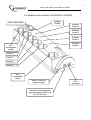
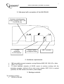
Silver Shield Power Manager
Silver Shield Power Manager 841
Silver Shield Power Manager S
(With built-in power supply unit)
SIS-PM / SiS-PM-841 / SIS-PMS User Manual
Table of contents
1. Introduction and features of the SiS-PM/SiS-PM-841/SiS-PMS
2. Indicators and controls of the SiS-PМ or SiS-PMS
3. Side panel with connectors of the SiS-PM-841
4. Hardware requirements
5. Package contents
6. Installation of SiS-PM(S)
7. Connection of other devices to the SiS-PM(S)
8. Switching SiS-PM(S) on and off, connection to the managing computer
9. Software installation
10. Power Manager Help
11. Audible signals or indicators
12. Technical specifications
13. Troubleshooting
Disclaimer
2
SIS-PM / SiS-PM-841 / SIS-PMS User Manual
3
1. Introduction and features of the SiS-PM/SiS-PM-841/SiS-PMS
Congratulations on purchasing the Silver shield Power Manager. Your SiS-PM or SiSPMS (hereinafter SiS-PM(S)) is an advanced surge protector with power management
features. Four sockets are individually manageable from the computer via the USB port
interface.
E.g. can be switched on/off, by timer schedule, or triggered by user or different
events. It is also possible to pre-program the unit event timer schedule and then
disconnect the SiS-PM(S) from the computer (hardware schedule) and use it elsewhere.
Additionally the hardware event schedule will work even with the managing computer
switched off.
SiS-PM Power manager software has the following main features:
• Manual on and off switching of every socket via the software control window;
• Switching sockets on and off according to the timer schedule of events, typical
applications include: “switch my peripherals on every working day at 8:50AM” etc
• Switching sockets on and off when a certain event occurs (Windows or other
programs startup/shutdown), typical applications include: “switch my scanner on
when I want to scan” or “switch my printer off whenever I exit Windows”
• The unit can be assigned a network name as a shared LAN resource and can
afterwards be accessed and managed from anywhere within the local area network.
• Preprogramming of the hardware-based event time schedule. The hardware
schedule will work even with the managing computer switched off provided that the
is connected to the optional power adapter. The unit will keep performing the
hardware time schedule even when the SiS-PM is temporarily switched off.
• Voltage monitor
• The software management supports any number of SiS-PM, SiS-PMS and MSiS-PM
connected to the computer.
• Management of SiS-PM(S) via the LAN and Internet.
• Command line interface support for user software applications is also possible.
SiS-PMS is an advanced surge protector with power management features. Four
sockets are individually manageable from the computer via the USB port interface on
the SiS-PMS. E.g. can be switched on/off, by timer schedule, or triggered by user or
different on-screen-software events (like: switch on my scanner if I start image editing
software, or switch on security lights and alarm when my webcam software detects
motion in the image)
It is also possible to pre-program a timer schedule and then disconnect the SiS-PMS
from the computer (hardware schedule) and use it else where. This hardware event
schedule will work even when the connected computer is switched off. The Built-in
transformer of SiS-PMS makes this possible.
SiS-PM-841 lets your external hardware (such as KVM switches *) control SiS-PM841 sockets, read the voltage being on the sockets through the PM interface.
SiS-PM-841 let’s you make a chain with 10 devices connected to one another to be
controlled by external hardware (for example - by KVM switches *)
* Supported models of KVM switches: CAS-441-PM, CAS-841-PM
4
SIS-PM / SiS-PM-841 / SIS-PMS User Manual
2. Indicators and controls of the SiS-PМ or SiS-PMS
Indicator
“POWER”
Main rocker switch
Indicator
Socket 4
Indicator
Socket 3
Indicator
Socket 2
Indicator
Socket 1
Nonmanageable
socket
Socket 4
Socket 3
Socket 2
Socket 1
Nonmanageable
socket
“Silence” button to
suppress beeps
Hardware schedule power
supply connector 9VDC 0,5A
For SIS-PM only
USB connector
SIS-PM / SiS-PM-841 / SIS-PMS User Manual
5
3. Side panel with connectors of the SiS-PM-841
Hardware schedule power
supply connector 9VDC 0,5A
For SiS-PM only
2 x RJ45
connectors
for PM interface
“Silence” button
to suppress beeps
USB - connector
4. Hardware requirements
•
•
•
IBM compatible personal computer running Windows 98SE, ME, 2000, XP or Vista.
USB 1.1 or 2.0 port.
To allow hardware schedule of SiS-PM events to continue working with the
managing computer switched off an extra power adapter 9VDC 0,5А is required
(optional). SiS-PMS contains the build in power adapter.
5. Package contents
The package contains:
•
SiS-PM or SiS-PMS
SIS-PM / SiS-PM-841 / SIS-PMS User Manual
•
•
•
•
6
User manual
USB cable;
CD with software
Adaptor(optional, not included) for SiS-PM only
6. Installation of SiS-PM(S)
•
•
•
•
It is strongly recommended to avoid damp or wet places for installation.
SiS-PM(S) should be connected to the European AC wall socket of the standard
DIN 49 440;
SiS-PM(S) can be connected to the computer first and then to the power socket or
vice-versa.
It is possible to connect the SiS-PM(S) to the power source via other multi-plugs,
surge protectors, voltage regulators or UPS.
7. Connection of other devices to the SiS-PM
•
•
•
•
•
•
•
Two (the first and the last) sockets of the SiS-PM(S) are marked with the symbol
. These two sockets are switched on and off by means of the main power
switch of the SiS-PM(S) and cannot be managed by the computer. It is suggested
to use these two sockets to power up the managing computer and the hardware
schedule adapter;(Optional for SiS-PM only)
The sockets: Socket 1, Socket 2, Socket 3 and Socket 4 can be managed or
preprogrammed by computer via the USB interface.
SiS-PM(S) can be used with other multi-plugs and/or surge protectors;
You are NOT to connect SiS-PM(S) to powerful machines with inductive type of
load, for example: welding machines, washing machines, electric drills etc...
SiS-PM-841 can be connected with CAS-441-PM, CAS-841-PM using CAT-5 cable
marked “Straight-Through Cable Pinout (T568B or T568А)” with sockets of PM
interface
To work with CAS-441-PM it needs to set device’s ID = 1. This can be done using
the utility software “SiS-PM-841 Configuration Tool” after the device has been
connected to PC through the USB-cable. To work with CAS-841-PM it needs to set a
unique ID for each connected device, which will be categorically associated with the
socket number in CAS-841-PM device.
You can connect up to 10pcs of CAS-841-PM at the same time. Connect the first
device to RJ-45 socket using the cable described above. Both RJ-45 sockets are
equal. In this way all devices should be connected in a chain, one SiS-PM-841 to
another.
SIS-PM / SiS-PM-841 / SIS-PMS User Manual
7
8. Switching SiS-PM(S) on and off,
connection to the managing computer
• The SiS-PM(S) should be switched on and off by means of the main rocker
•
•
•
•
•
•
•
•
•
switch.(Red Plastic switch)
To protect electrical installations from possible high current and short circuit the SiSPM(S) is equipped with the automatic circuit breaker;
The power voltage for the manageable part of SiS-PM(S) is derived from the USB
port of the managing computer, (or when the USB cable is disconnected, from the
external power adapter for the SiS-PM and from the build in power adapter for the
SiS-PMS).
If the SiS-PM(S) is switched on then the red indicator “POWER” is lit up. In this case
both sockets marked with
are now “live” and connected to the power supply;
The manageable sockets of SiS-PM(S) (marked with Socket numbers) can be
connected to or disconnected from the power supply depending on the computer’s
initiated or preprogrammed events. The current status of each manageable socket is
represented by the corresponding indicator. E.g. Red lamp will be lit if socket has
power to it.
SiS-PM-841 sockets can be controlled by PC and by other external device which can
support PM-interface, in particular – CAS-441-PM, CAS-841-PM. Supervisory external
device can read status(*) of the controlled socket. For detailed information please
refer to the user’s manual of the connected device.
The moment the SiS-PM(S) is connected to the working computer via the USB cable
an audible beep will be heard indicating that the SiS-PM(S) is operating correctly;
If you want the hardware event schedule to work with the manageable computer
switched off, the optional power adapter 9VDC 0,5A should be connected to one of
the sockets marked with the sign
, (or into a wall socket),and its VDC
connector should be connected to the corresponding socket +9VDC of the SiS-PM.
SiS-PMS contains the build in power adapter.
Install enclosed software Gembird Power Manager.
Further follow the software guide instructions (see below).
* Status – means voltage present on the controlled socket.
9. Software installation
a. Insert CD with the software into the computers CD-ROM drive;
b. If for any reason the automatic setup does not work, then open the CD-ROM drive
in the My computer window and launch SETUP.EXE from the CD;
c. Follow instructions of the installation software;
SIS-PM / SiS-PM-841 / SIS-PMS User Manual
8
10 Power Manager Help
The Settings dialog box allows you to change settings for the device sockets. You may
choose the device and the socket from the "Device" and "Socket" drop down list-boxes.
•
It is possible to name and assign a certain icon to the device and socket (for
example “Printer” or “Scanner”) using the "Rename" button.
•
Check the "Disable device beeper" checkbox to disable the built-in SiS-PM beeper.
•
Check the "Show socket switch icon" checkbox if you want to put the icon of the
socket into the system tray. Such an icon is a fast way to switch the device
connected to the socket on/off or check its status.
•
You can also assign a hot key to switch the socket on/off. Check the "Switch ON"
and "Switch OFF" checkboxes and specify the hot keys.
•
To switch the socket on/off on Windows startup, check the "On Windows startup"
checkbox and choose the required action.
•
To switch the socket on/off on Windows shutdown, check the "On Windows
shutdown" checkbox and choose the required action.
•
Check the "When alarm goes on start application" checkbox and click the "Browse"
button to select the program which will be launched when the power supply to the
socket does not match the required event (i.e. the socket must be on, but there is no
power supplied to it yet).
•
Check the "When alarm goes off start application" checkbox and click the "Browse"
button to select the program, which will be launched after the alarm state (see
above) is resolved.
•
To manage SiS-PM(S) from the LAN and/or via Internet, press the button "Device
sharing...". A dialog box "Device sharing" will appear. Set the checkbox "Share this
device via network" if you want to enable the network access to the device. To
prevent unauthorized access to the SiS-PM(S) enter the access password in the field
"Password". Note: to let SiS-PM(S) work via the network the port 6100 should be
open. Contact your LAN administrator for further details.
Using the Timer schedule dialog box you can create the hardware timer schedule:
•
To add a new record, click the "Add" button. The dialog "Add entry" will appear. In
the dialog box, specify the required time interval and the action.
•
To edit the record, select it and click the "Edit" button or just double click on the
entry.
•
To remove the record, select it and click the "Remove" button. You can select
multiple entries using Ctrl and shift keys. You can also remove all entries from the
schedule by clicking the "Clear" button.
SIS-PM / SiS-PM-841 / SIS-PMS User Manual
9
•
To repeat your event (for example if you want to perform the same events every
day) use the "Loop" button and specify the loop time period in the "Edit loop period"
dialog.
•
After the schedule record has been created, click the "Apply" button to apply the
hardware timer schedule changes. In case of the wrong entries, they will be
highlighted and an error message will appear. Click the "Apply" button again after
correcting all the errors.
Hint: Use the popup menu which can be activated by a right mouse button click on the
table.
The following rules apply for creating a correct schedule:
1. The event time should not be expired.( Date or time must be a future event)
2. There should be no duplicate entry with the same parameters.
3. The total quantity of records should not exceed 16.
4. The interval between the present time and the latest entry should not exceed 180
days.
5. The loop period should exceed the interval between the first and the last entry with
at least one minute. If the event time of the first record is after 45 days from the
present time, the loop period should also not exceed the difference between the time
of the first entry and the present time plus 45 days.
6. Loop period should not exceed 180 days.
7. It is also possible that the total quantity of the records would be less than 16. Each
loop time interval greater than 11.3 days decreases the maximum quantity of entries
by one.
8. Without loop the total schedule time interval should not exceed 215 days.
Using the Switching tasks dialog you can create the software events schedule:
•
To add a new task, click the "Add" button. The "Add task" dialog will appear. In the
"Add task" dialog, check "Switch ON time" and/or "Switch OFF time" checkboxes and
specify the time to switch the socked on and/or off. If you want the same event to
be performed periodically, check "Perform every" checkbox and specify the time
interval. You can also add remarks about the task in the "Comment" field. To disable
the task, uncheck the "Enabled" checkbox and to enable the task again, re-check the
checkbox.
•
To edit the task, select it and click the "Edit" button or just double click on the task.
•
To remove the task select it and click the "Remove" button. You may select multiple
tasks using ctrl and shift keys. You can also remove all tasks by clicking the "Clear"
button.
SIS-PM / SiS-PM-841 / SIS-PMS User Manual
10
Hint: Use the popup menu which can be activated by a right mouse button click on the
table.
Using the Application events dialog box you can specify events with the sockets when a
certain application is initiated or closed down. You can also assign folders with the sockets
to watch for particular file placing and removal.
•
To add a new program event, click the "Add app" button. The "Add program event"
dialog will appear. Specify the application title and path to it using the "Browse"
button or typing it manually in the "Title" and "Path name" fields. If you use the
"Browse" button you can also specify a link to the application. The application title
and path name will be taken from the link if possible. After you have specified the
application, check "On run" and/or "On exit" and select the event. Note: The socket
is switched on/off only when the first window of the selected application is launched
or when the last window of the application is closed. For example, you can switch
the ADSL modem on/off when Internet Explorer is started up or closed. To disable
the task, uncheck the "Enabled" checkbox, to enable the task set the checkbox again.
•
To add a new file event, click the "Add folder" button. The "Add file event" dialog will
appear. Specify the event title and path folder you would like to look into for files
using the "Browse" button or typing it manually in the "Title" and "Path name" fields.
Specify the "File name" mask using wildcard characters: "*", "?". After you have
specified the folder and file name, check "On placing" and/or "On removal" and
select the event and/or delay. Note: The socket is switched on/off only when the first
file is placed and the last file is removed from the folder. To disable the task,
uncheck the "Enabled" checkbox, to enable the task set the checkbox again.
•
To edit the event, select it and click the "Edit" button, or just double click on the
event.
•
To remove the event, select it and click the "Remove" button. You can select
multiple events using ctrl and shift keys. You can also remove all events by clicking
the "Clear" button.
Hint: Use the popup menu which can be activated by the right mouse button click over the
table.
Hint: Use "Add folder" button to assign "systemroot\\system32\\spool\\printers" folder to
start
managing
your
printer.
Hint: If you have several printers connected to the same computer it would be convenient
to move default spool directory of each printer to a separate location.
Network devices
The dialog box Network Devices allows connection to the shared SiS-PM(S) from remote
computers.
•
To add a new remote SiS-PM, press "Add" button. You will see the dialog box "Add
network device". Enter the network name of the computer, connected to the SiS-PM
in the field "Hostname". Enter the name of the target SiS-PM in the field "Device
name". Enter access password in the field "Password". To disconnect from the device
SIS-PM / SiS-PM-841 / SIS-PMS User Manual
11
uncheck the option "Enable", set this option on again to regain access. To locate the
shared device in your local network, click the button "Find". A dialog box "Find
network device" will appear. Choose the computer by using the mouse double-click
and then the device and click "OK" button.
•
To edit the network device, select it and click the "Edit" button, or just double click
on the network device.
•
To remove the network device, select it and click the "Remove" button. You can
select multiple network devices using ctrl and shift keys. You can also remove all
network devices by clicking the "Clear" button.
Hint: Use the popup menu which can be activated by the right mouse button click on the
table.
Command line interface
To let people switch sockets from the user applications the following command line
interface syntax is supported:
•
pm.exe -[on | off] -device name -socket name
Examples:
•
"C:\Program Files\Gembird\Power Manager\pm.exe" -on -sis-pm -socket1
•
"E:\Utils\PM3\pm.exe" -off -my sis-pm -table lamp
Execute pm.exe with -info key to get the complete information on current device status. For
each of the connected devices the following information is provided and available from
Info.ini file in the PowerManager folder:
•
DeviceName - the user specified device name;
•
Socket#name, where # is replaced by a certain socket number - the user specified
socket name;
•
Socket#SwitchState, where # is replaced by a certain socket number - TRUE, when
the socket is switched on, FALSE, when the socket is switched off;
•
Socket#VoltageState, where # is replaced by a certain socket number - TRUE, when
voltage presence on the socket is detected, FALSE, when there is no voltage on the
socket;
Example:
•
pm.exe -info
Note: Each use of this command line option totally overrides the data in Info.ini file.
Note: Power Manager should be launched.
SIS-PM / SiS-PM-841 / SIS-PMS User Manual
12
11. Audible beeps and indicators
•
•
•
•
•
•
•
Long beep – will be heard after the SiS-PM is connected to the computer USB port
after the self test;
Short beep – will be heard by switching of the manageable sockets on and off;
Continuing beeps – hardware event schedule is lost – for example if the power
supply was disrupted for a long period. These beeps can be stopped by pressing the
Silence button on the side of the SiS-PM(S);
Alarm beep – will be heard if the managing command cannot be completed. For
example if there is a command to switch the socket on but SiS-PM is disconnected
from the power supply. The alarm will be heard every second for a minute, after that
every 8 seconds.
Indicator “POWER” is on - means there is power on the sockets marked with the
sign
;
Indicator “Socket x” is on – means there is power in this particular socket
Main rocker switch is light up – means SiS-PM(S) is connected to the power supply
and the SiS-PM(S) is active.
12. Technical specifications
•
•
•
•
•
•
•
•
•
•
•
•
•
Input voltage 220 – 230 VAC~ 50 – 60 Hz;
Maximum load current 10A;
Maximum current consumed by the SiS-PM from the computer USB port - 350mA;
Maximum current consumed by the SiS-PMS from the power supply 220 – 230
VAC~- 25mA;
Maximum quantity of SiS-PM connected to one computer at the same time – no
restrictions (only restricted by the maximum allowed quantity of the USB devices);
Plug and Play;
Hardware schedule restrictions;
Maximum number of independent hardware schedules - 16;
Time interval between the events – from 1 minute to 180 days;
Timer accuracy – not more than 3 seconds error per day.
Working temperature range: from +10 to +40 degrees C;
Size ( without power adapter and USB cable) 460*140*65
Weight – not more than 1,3 kg for SiS-PM or not more than 1,45 kg for SiS-PMS
SIS-PM / SiS-PM-841 / SIS-PMS User Manual
13
13. Troubleshooting
Problem
Solution
The load connected to the unit is too high,
some of the devices connected to the SiSThe circuit breaker is activated.(Tripped).
PM(S) should be disconnected and the
circuit breaker should be reset.
The switching command is not carried out, There is no power supply to the SiS-PM(S).
the rocker switch and indicators are not lit Please, make sure the SiS-PM(S) is
up, the alarm beep is heard
connected to the power supply and the
rocker switch is switched on
Check if SiS-PM(S) is properly connected
to your computer, check if the USB
connectors/cables are not damaged. If you
Software reports "Device I/O request
use a USB hub, make sure it is not
error.".
defective. If the problem cannot be solved,
contact Gembird support team at
http://www.gmb.nl/forum/.
Disclaimer
•
•
•
No effort have been spared to ensure that the information in this manual is correct and
complete to the best of our knowledge. However no liability is accepted for any errors or
omissions. Gembird Electronics reserves the right to change the specifications of the
hardware and software described in this manual without prior notice.
No part of this manual may be reproduced, transmitted or translated in any language in
any form, by any means, without the prior written permission of Gembird Electronics
Ltd.
Gembird Electronics makes no warranties for damages resulting from corrupted or lost
data due to a mistaken operation or malfunction of the SiS-PM or the Power Manager
software.
Gembird® is a registered trademark of GMB Tech (Holland) Bv.
Silver shield™ is a trademark of Gembird Electronics Ltd.
Other names or products not mentioned above may be registered trademarks or
trademarks of their respective owners.
Copyright © 2007 Gembird Electronics Ltd. All rights reserved.