1
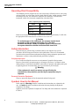
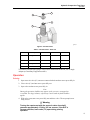
99 Washington Street
Melrose, MA 02176
Phone 781-665-1400
Toll Free 1-800-517-8431
Visit us at www.TestEquipmentDepot.com
P5514, P5514-V &
P5514-EP
Hydraulic Comparison Test Pump
Users Manual
PN 3952337
November 2010
© 2010 Fluke Corporation. All rights reserved. Printed in USA. Specifications are subject to change without notice.
All product names are trademarks of their respective companies.
LIMITED WARRANTY AND LIMITATION OF LIABILITY
Each Fluke product is warranted to be free from defects in material and workmanship under normal use and
service. The warranty period is one year and begins on the date of shipment. Parts, product repairs, and
services are warranted for 90 days. This warranty extends only to the original buyer or end-user customer of
a Fluke authorized reseller, and does not apply to fuses, disposable batteries, or to any product which, in
Fluke's opinion, has been misused, altered, neglected, contaminated, or damaged by accident or abnormal
conditions of operation or handling. Fluke warrants that software will operate substantially in accordance
with its functional specifications for 90 days and that it has been properly recorded on non-defective media.
Fluke does not warrant that software will be error free or operate without interruption.
Fluke authorized resellers shall extend this warranty on new and unused products to end-user customers
only but have no authority to extend a greater or different warranty on behalf of Fluke. Warranty support is
available only if product is purchased through a Fluke authorized sales outlet or Buyer has paid the
applicable international price. Fluke reserves the right to invoice Buyer for importation costs of
repair/replacement parts when product purchased in one country is submitted for repair in another country.
Fluke's warranty obligation is limited, at Fluke's option, to refund of the purchase price, free of charge repair,
or replacement of a defective product which is returned to a Fluke authorized service center within the
warranty period.
To obtain warranty service, contact your nearest Fluke authorized service center to obtain return
authorization information, then send the product to that service center, with a description of the difficulty,
postage and insurance prepaid (FOB Destination). Fluke assumes no risk for damage in transit. Following
warranty repair, the product will be returned to Buyer, transportation prepaid (FOB Destination). If Fluke
determines that failure was caused by neglect, misuse, contamination, alteration, accident, or abnormal
condition of operation or handling, including overvoltage failures caused by use outside the product’s
specified rating, or normal wear and tear of mechanical components, Fluke will provide an estimate of repair
costs and obtain authorization before commencing the work. Following repair, the product will be returned to
the Buyer transportation prepaid and the Buyer will be billed for the repair and return transportation charges
(FOB Shipping Point).
THIS WARRANTY IS BUYER'S SOLE AND EXCLUSIVE REMEDY AND IS IN LIEU OF ALL OTHER
WARRANTIES, EXPRESS OR IMPLIED, INCLUDING BUT NOT LIMITED TO ANY IMPLIED WARRANTY
OF MERCHANTABILITY OR FITNESS FOR A PARTICULAR PURPOSE. FLUKE SHALL NOT BE LIABLE
FOR ANY SPECIAL, INDIRECT, INCIDENTAL, OR CONSEQUENTIAL DAMAGES OR LOSSES,
INCLUDING LOSS OF DATA, ARISING FROM ANY CAUSE OR THEORY.
Since some countries or states do not allow limitation of the term of an implied warranty, or exclusion or
limitation of incidental or consequential damages, the limitations and exclusions of this warranty may not
apply to every buyer. If any provision of this Warranty is held invalid or unenforceable by a court or other
decision-maker of competent jurisdiction, such holding will not affect the validity or enforceability of any other
provision.
Table of Contents
Title
Preparation .........................................................................................................
How to Contact Fluke ........................................................................................
Operating Fluid Compatibility...........................................................................
Safety Information .............................................................................................
Compressed Liquid........................................................................................
Personal Protective Equipment......................................................................
Symbols Used in this Manual ............................................................................
Connections .......................................................................................................
Connect the Gauge ........................................................................................
Connect the Test Port Insert ..........................................................................
Operation ...........................................................................................................
Priming ..........................................................................................................
Operation .......................................................................................................
Maintenance and Servicing................................................................................
Screw Press Seals ..........................................................................................
Complete Disassembly ..................................................................................
Ancillary Equipment..........................................................................................
Angle Adapter, P5543 ...................................................................................
Pointer Remover/Punch, P5551.....................................................................
i
Page
1
1
2
2
2
2
2
3
4
4
5
5
6
6
6
7
11
11
11
P5514, P5514-V & P5514-EP
Users Manual
ii
List of Tables
Table
1.
2.
3.
4.
5.
Title
Operating Fluid Compatibility ...............................................................................
Symbols..................................................................................................................
Test Port Insert - Parts List.....................................................................................
Seal Kit - Part Numbers .........................................................................................
Screw Press Assembly - Parts List.........................................................................
Page
2
3
5
6
10
iii
Test Equipment Depot - 800.517.8431 - 99 Washington Street Melrose, MA 02176
TestEquipmentDepot.com
P5514, P5514-V & P5514-EP
Users Manual
iv
List of Figures
Figure
Title
1.
2.
3.
4.
5.
6.
Connecting the Gauge ............................................................................................
Test Port Insert .......................................................................................................
Reservoir and Test Port Assemblies.......................................................................
Screw Press Assembly ...........................................................................................
Angle Adapter ........................................................................................................
Pointer Remover/Punch..........................................................................................
v
Page
4
5
9
9
11
11
P5514, P5514-V & P5514-EP
Users Manual
vi
Preparation
The Hydraulic Comparison Test Pump User’s Manual covers the following instruments:
the P5514, P5514-V, and the P5514-EP.
The Comparison Test Pump is used for checking pressure-measuring instruments against
Master Test Gauges.
Note
The terms ”Master Test Gauge” and “Gauge” in this document refer to
any pressure-measuring instrument such as Transfer Standards, Digital
Calibrators, and Transducers.
This system is only as accurate as the Master Test Gauge used. The Master Test Gauge
must be regularly calibrated on a Primary Reference Standard (such as a Deadweight
Tester) to ensure accuracy is maintained.
The comparison test pump should be mounted securely to a stable workbench or similar
surface. Four mounting holes are provided in the pump stand for this purpose.
1
P5514, P5514-V & P5514-EP
Users Manual
Operating Fluid Compatibility
The standard system is designed for use with a wide range of fluids; however, the O-ring
seals are Nitrile; use of solvents, fuel oils, brake fluids or other, similar aggressive fluids
can damage the seals. The table below details the two alternative versions of this
instrument, which offer increased compatibility with other fluids.
Table 1. Operating Fluid Compatibility
Model
O Rings
P5514
Nitrile
P5514-V
Viton
P5514-EP
Ethylene Propylene
Rotate reservoir dust cover through ½ turn and fill reservoir approximately 3/4 full with
the appropriate fluid. Rotate dust cover back to cover reservoir.
W Caution
To avoid damage to the instrument, the operator should check
the quality of the operating fluid during use. If the fluid
becomes discolored, cloudy or particles appear in the reservoir,
the system should be drained and flushed with clean fluid.
Safety Information
The following are general safety precautions that are not related to any specific
procedures and do not appear elsewhere in this publication. These are recommended
precautions that personnel must understand and apply during equipment operation and
maintenance to ensure safety and health and protection of property.
Compressed Liquid
Use of compressed liquids can create an environment of propelled foreign matter.
Pressure system safety precautions apply to all ranges of pressure. Care must be taken
during testing to ensure that all hydraulic connections are properly and tightly made prior
to applying pressure. Personnel must wear eye protection to prevent injury.
W Warning
If the equipment is used in a manner not specified by the
manufacturer, the protection provided by the equipment may be
impaired.
Personal Protective Equipment
Wear eye protection approved for the materials and tools being used.
Symbols Used in this Manual
In this manual, a Warning identifies conditions and actions that pose a hazard to the
user. A Caution identifies conditions and actions that may damage the Hydraulic
Comparison Test Pump.
Symbols used on the Hydraulic Comparison Test Pump and in this manual are explained
in Table 2.
2
Test Equipment Depot - 800.517.8431 - 99 Washington Street Melrose, MA 02176
TestEquipmentDepot.com
Hydraulic Comparison Test Pump
Connections
Table 2. Symbols
Symbol
B
J
W
~
Description
AC (Alternating Current)
Earth Ground
Important Information: refer to manual
Do not dispose of this product as unsorted
municipal waste. Go to Fluke’s website for
recycling information.
Connections
Fit the device under test (DUT) to the test port using the method described below:
W Caution
Ensure that all devices are internally clean and free from
contamination before connecting to the tester.
Particle contamination can damage the sensitive piston
assemblies, valve seats, and screw pump.
To avoid cross-contamination from other fluids and protect the
system from particulates, we recommend the use of a
Liquid-to-Liquid Separator (see Section 5, Ancillary Equipment).
W Warning
DO NOT use Teflon/PTFE tape on these connections as this will
prevent correct sealing. The Gauge Adapter sealing system is
designed for hand-tight sealing up to 20,000 psi / 1,400
bar-wrenches or similar tools are not required — over
tightening can cause damage to threads or sealing faces.
Before connection, ensure that there is an O-ring fitted to the
test port.
Check that the sealing face of the device to be fitted is clean
and undamaged, as scratches or dents can form leak-paths.
Note
The thread on the test port, and the lower part of the gauge adapters is
LEFT-HANDED. The following procedure details the correct method for
mounting devices using these adapters.
3
P5514, P5514-V & P5514-EP
Users Manual
1
2
3
4
Figure 1. Connecting the Gauge
gjq001.eps
Connect the Gauge
Refer to Figure 1 for steps 1 to 4.
1. Screw the appropriate gauge adapter fully on to the instrument to be tested.
2. Screw assembly down COUNTER-CLOCKWISE on to test port.
Note
Hand-tight is sufficient; ensure that the bottom face contacts the O-ring on
the test port.
3. To adjust the position to face forward, hold the gauge adapter and turn the instrument
COUNTER-CLOCKWISE, so that it faces forward.
4. Hold the instrument steady, while turning the gauge adapter
COUNTER-CLOCKWISE until it pulls down onto the O-ring.
Connect the Test Port Insert
For devices with 1/8 BSP or NPT mounting threads, the diameter of the thread is very
close to the effective sealing diameter of the O-ring fitted to the test port.
This can make it difficult to achieve a good seal. When mounting these devices, use the
test port insert (stored in the spare seals container) as shown Figure 2.
4
Hydraulic Comparison Test Pump
Operation
1
2
3
4
gjq002.eps
Figure 2. Test Port Insert
Table 3. Test Port Insert - Parts List
Item
Description
P5515
P5515-V
P5515-EP
3867888
1
O Ring
3865142
3865163
2
Test Port Insert
3919892
—
3
O Ring
3883397
3883521
4
Test Port
3918298
—
—
3867895
—
To calibrate panel-mounted gauges with pressure connections in the rear, use an Angle
Adapter (see Ancillary Equipment section).
Operation
Priming
1. Open reservoir valve (13) one turn counter-clockwise and turn screw press fully in.
2. Close valve (13) and turn screw press fully out.
3. Open valve and turn screw press fully in.
Note
During this operation, bubbles may appear in the reservoir, as trapped air
is expelled. For large volumes, repeat steps 2 and 3 until no further bubbles
appear.
4. With valve open, turn screw press fully out and close valve. The test pump is now
ready for use.
W Warning
Turning the capstan out with the reservoir valve closed will
generate approximately 15 inHg / 0.5 bar vacuum. If the DUT is
vacuum sensitive, leave valve (13) open during priming
operation.
5
P5514, P5514-V & P5514-EP
Users Manual
Operation
W Warning
Do not exceed the maximum working pressure of the
instrument (stated on the instrument label).
1. Turn the screw press in to generate pressure.
2. Allow a few moments for the system to stabilize before taking any readings,
especially after large changes in system pressure.
Note
Large, sudden changes in pressure will cause the system temperature to
rise or fall, which can cause instrument readings to change as the fluid in
the system expands or contracts, thus increasing or decreasing the
pressure.
3. Compare the reading of the gauge under test with that of the master gauge.
4. For the next higher calibration point, repeat from Priming, Step 1.
5. To measure reducing pressures, turn the screw press out (counter-clockwise).
6. Depressurize the system by turning the screw press FULLY OUT, then open the
reservoir valve
W Caution
Never release the system pressure by using the reservoir valve
alone, as sudden depressurization will “shock” the system,
which may cause damage to sensitive instruments attached
to it.
Maintenance and Servicing
The Figures on the following pages detail the components of each assembly, together
with the relevant part numbers. Where “ASSY” appears as a part number, this indicates
that this particular component is associated with other components in an assembly for
replacement purposes.
Before beginning any maintenance, remove any instruments that may be mounted to the
test pump, and drain the fluid from the system.
Table 4. Seal Kit - Part Numbers
Model
Seal Kit P/N
P5514
3891113
P5514-V
3891124
P5514-EP
3891136
Screw Press Seals
1. Turn the screw press out so that there is a distance of at least 1” / 2.5cm between the
large union nut at the end of the barrel and the capstan hub.
2. Unscrew the union nut and withdraw the lead screw assembly (24) from the barrel,
taking care not to drop the rambler (22).
3. Inspect the seals for signs of wear or damage, replace as necessary.
6
Hydraulic Comparison Test Pump
Maintenance and Servicing
4. The white, anti-extrusion ring (21) is a PTFE spiral, and can be removed by
“unwinding” it from the rambler.
5. When removing the rambler seal (20), take care not to use any tool that may have a
sharp edge that will scratch the surfaces of the rambler, otherwise it may leak when
reassembled.
6. The replacement rambler seal can be eased over the front of the rambler, and into
the groove.
7. Similarly, the new anti-extrusion ring can be “wound” into the groove in the rambler,
behind the rambler seal.
8. If the rambler has been separated from the lead screw, ensure that the ball (23) is
correctly fitted before reassembly.
9. Ensure that the rambler assembly is correctly located on the end of the lead screw
assembly. Carefully introduce the rambler into the open end of the barrel; making
sure that it does not tilt when entering the barrel.
10. Push the lead screw assembly fully in to the barrel, ensuring that the key in the nut
locates correctly in the slot in the barrel.
11. Re-tighten the barrel union nut.
W Caution
If the lead screw assembly (24) shows signs of excessive wear,
then it is very likely that the associated components have worn
also; therefore, the screw press assembly is available as a
spare part.
Complete Disassembly
1. Remove the screw press assembly as described above.
2. Unscrew and remove valve stem (13), taking care not to lose spring (12) and nylon
washer (11).
3. Remove reservoir cover (10).
4. Unscrew locknut (9), and remove reservoir (8).
5. Unscrew valve body (6), taking care not to lose bonded seal (7) or O-ring (5).
6. Remove banjo bolts (1), together with banjo test ports (3), taking care not to lose
O-rings (2).
7. Disconnect the stand (15) from the bench. Remove screws (14), and tilt
manifold/barrel assembly downward and pass it out of the bottom of the stand.
8. To remove the barrel (19), the locknut (18) must be loosened approximately 1/2 turn.
The barrel can then be unscrewed from the manifold (16).
9. Before re-fitting the barrel, ensure that the barrel seal (17) is correctly located in the
counter-bore in the front of the barrel. Screw the barrel fully in to the test station, and
secure with the locknut.
10. Inspect all seals for wear or damage — replace as necessary.
7
Test Equipment Depot - 800.517.8431 - 99 Washington Street Melrose, MA 02176
TestEquipmentDepot.com
P5514, P5514-V & P5514-EP
Users Manual
W Caution
If the rambler shows signs of wear, then it is very likely that the
main bore in the barrel is worn also. If the bore is worn or
scratched, it will not seal correctly, and may leak under
pressure.
11. Re-assembly is the reverse of the above. Ensure that all seals and sealing surfaces are
clean and undamaged.
13
12
11
10
9
8
7
6
14
14
4
4
5
3
1
3
1
2
2
15
Figure 3. Reservoir and Test Port Assemblies
8
gjq003.eps
Hydraulic Comparison Test Pump
Maintenance and Servicing
17
18
19
26
16
25
21
20
22
23
24
25
26
Figure 4. Screw Press Assembly
gjq004.eps
9
P5514, P5514-V & P5514-EP
Users Manual
Table 5. Screw Press Assembly - Parts List
Item
10
Description
Part
P5514
P5514-V
P5514-EP
1
Banjo Bolt
3918323
—
—
2
O Ring
3905652
3919393
3926936
3
Banjo Test Port
3918298
—
—
4
O Ring
3883397
3883521
3867895
5
O Ring
3864857
3865277
3921986
6
Valve Body
3923785
—
—
7
Bonded Seal
3862349
3922096
3922043
8
Reservoir
3919463
—
—
9
Locknut
3918244
—
—
10
Reservoir Cover
3918350
—
—
11
Washer
3916458
—
—
12
Spring
3922786
—
—
13
Valve Stem Assembly
3885982
—
—
14
Screw
3909422
—
—
15
Pump Stand
3918271
—
—
16
Manifold
3918280
—
—
17
O Ring
3864711
3865359
3865576
18
Locknut
3917862
—
—
19
Barrel
3919630
—
—
20
O Ring
3864782
3865214
3865541
21
Back-Up Ring
3920516
—
—
22
Rambler
3919611
—
—
23
Ball
3917855
—
—
24
Lead Screw Assembly
3885982
—
—
25
Spoke
3921672
—
—
26
Knob
3917843
—
—
Hydraulic Comparison Test Pump
Ancillary Equipment
Ancillary Equipment
Angle Adapter, P5543
To calibrate gauges with the pressure connection on the rear (e.g. panel-mount gauges) in
their correct position, an angle adapter should be used. The angle adapter fits directly
onto the test station, converting it through 90 degrees, allowing the standard adapters to
be used.
Figure 5. Angle Adapter
gjn022.bmp
Pointer Remover/Punch, P5551
To remove and refit the pointer of a pressure gauge, use the pointer remover/punch
instrument. This tool has a spring-loaded plunger to quickly and consistently refit the
pointer.
Figure 6. Pointer Remover/Punch
gjn023.bmp
11
P5514, P5514-V & P5514-EP
Users Manual
12
Test Equipment Depot - 800.517.8431 - 99 Washington Street Melrose, MA 02176
TestEquipmentDepot.com