1
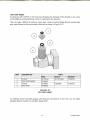
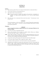
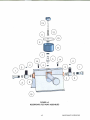
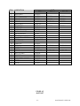
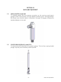
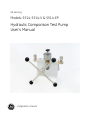
GE Sensing
Models: 5514; 5514-V & 5514-EP
Hydraulic Comparison Test Pump
User’s Manual
imagination at work
HYDRAULIC COMPARISON TEST PUMP
MODELS: 5514; 5514-V & 5514-EP
USER’S MANUAL
GE SENSING
10311 WESTPARK DRIVE
HOUSTON, TEXAS 77042
(713) 975 0547 FAX: (713) 975 6338
Release: 5514M-1D01
Revision: B
Date: 11/07/06
WARRANTY
GE Sensing warrants its products to conform to or exceed the specifications as set forth in its
catalogs in use at the time of sale and reserves the right, at its own discretion, without notice
and without making similar changes in articles previously manufactured, to make changes
in materials, designs, finish, or specifications.
GE Sensing warrants products of its own factory against defects of material or workmanship
for a period of one year from date of shipment.
Liability of GE Sensing under this warranty shall be limited to replacing, free of charge (FOB
Houston, Texas), any such parts proving defective within the period of this warranty, but will
not be responsible for transportation charges or consequential damages.
The warranty is not made for products manufactured by others which are illustrated and
described in GE Sensing catalogs or incorporated in GE Sensing products in essentially the
same form as supplied by the original manufacturer.
However, GE Sensing agrees to use its best efforts to have original suppliers make good their
warranties.
COPYRIGHT NOTICE
Copyright © 2006 by GE Sensing. All rights reserved. This document may not be reproduced
in part or in whole without the express written consent of GE Sensing.
DISCLAIMER
No representations or warranties are made with respect to the contents of this user’s
manual. Further, GE Sensing reserves the right to revise this manual and to make changes
from time to time in the content hereof without obligation to notify any person of such
revision.
TRADEMARK NOTICE
is a registered trademark of General Electric Corporation.
Trademarks or trade names are subject to state and federal laws concerning their
unauthorized use or other infringements. The fact that the product marks or names in this
manual do not bear a trademark symbol DOES NOT mean that the product name of mark is
not registered as a trademark or trade name. Any queries concerning the ownership or
existence of any trademarks or trade names mentioned in this manual should be
independently confirmed with the manufacturer or distributor of the product.
ii
REVISION NOTICE
RELEASE
NUMBER
REV.
DATE OF
RELEASE
5514M-1D01
A
08/18/06
Original release per DC/RO 25178
5514M-1D01
B
11/07/06
Model numbers modified per DC/RO 25272
DESCRIPTION
iii
SAFETY SUMMARY
The following are general safety precautions that are not related to any specific procedures
and do not appear elsewhere in this publication. These are recommended precautions that
personnel must understand and apply during equipment operation and maintenance to
ensure safety and health and protection of property.
COMPRESSED LIQUID
Use of compressed liquids can create an environment of propelled foreign matter. Pressure
system safety precautions apply to all ranges of pressure. Care must be taken during testing
to ensure that all hydraulic connections are properly and tightly made prior to applying
pressure. Personnel must wear eye protection to prevent injury.
PERSONAL PROTECTIVE EQUIPMENT
Wear eye protection approved for the materials and tools being used.
iv
TABLE OF CONTENTS
WARRANTY .................................................................................................................................................................... ii
COPYRIGHT NOTICE .................................................................................................................................................. ii
DISCLAIMER ................................................................................................................................................................... ii
TRADEMARK NOTICE ................................................................................................................................................ ii
REVISION NOTICE ...................................................................................................................................................... iii
SAFETY SUMMARY ..................................................................................................................................................... iv
COMPRESSED LIQUID .............................................................................................................................................. iv
PERSONAL PROTECTIVE EQUIPMENT .............................................................................................................. iv
TABLE OF CONTENTS ................................................................................................................................................. v
LIST OF FIGURES ......................................................................................................................................................... vi
1.0
PREPARATION ........................................................................................................................................... 1-1
1.1
OPERATING FLUID COMPATIBILITY...................................................................................... 1-1
2.0
CONNECTIONS ......................................................................................................................................... 2-1
3.0
OPERATION ................................................................................................................................................ 3-1
4.0
MAINTENANCE & SERVICING ............................................................................................................
4.1
TOP PLATE REMOVAL ...............................................................................................................
4.2
SCREW PUMP ASSEMBLY .......................................................................................................
4.3
PRIMING PUMP ASSEMBLY ....................................................................................................
4.4
CHECK VALVES ...........................................................................................................................
4.5
RESERVOIR ASSEMBLY ............................................................................................................
5.0
ANCILLIARY EQUIPMENT ..................................................................................................................... 5-1
4-1
4-1
4-2
4-4
4-6
4-8
LIST OF FIGURES
Figure 1-1
Hydraulic Circuit Schematic................................................................................................... 1-1
Figure 2-2A
Figure 2-2B
Figure 2-2C
Making pressure Connections .............................................................................................. 2-3
Making Pressure Connections .............................................................................................. 2-4
Test Port Insert............................................................................................................................. 2-5
Figure 4-1
Figure 4-2
Figure 4-3
Reservoir & Test Port Assemblies ........................................................................................ 4-3
Screw Pump Assembly............................................................................................................. 4-5
Parts List ......................................................................................................................................... 4-7
v
SECTION 1.0
PREPARATION
The Comparison Test Pump is used for checking pressure-measuring instruments against
Master Test Gauges.
Note: The terms ”Master Test Gauge” and “Gauge” in this document refer to any pressuremeasuring instrument such as Transfer Standards, Digital Calibrators and
Transducers.
This system is only as accurate as the Master Test Gauge used. The Master Test Gauge
must be regularly calibrated on a Primary Reference Standard (such as a Deadweight Tester)
to ensure accuracy is maintained.
The comparison test pump should be mounted securely to a stable workbench or similar
surface. Four mounting holes are provided in the pump stand for this purpose.
1.1
OPERATING FLUID COMPATABILITY
The standard system is designed for use with a wide range of fluids, however, the O-ring
seals are Nitrile; use of solvents, fuel oils, brake fluids or other, similar aggressive fluids can
damage the seals. The table below details the two alternative versions of this instrument,
which offer increased compatibility with other fluids.
Model
5514
5514-V
5514-EP
O Rings
Nitrile
Viton
Ethylene Propylene
Rotate reservoir dust cover through ½ turn and fill reservoir approximately ¾ full with the
appropriate fluid. Rotate dust cover back to cover reservoir.
WARNING
To avoid damage to the instrument, the operator should check the quality of the operating
fluid during use. If the fluid becomes discolored, cloudy or particles appear in the reservoir,
the system should be drained and flushed with clean fluid.
1-1
PREPARATION
THIS PAGE INTENTIONALLY LEFT BLANK
1-2
PREPARATION
SECTION 2.0
CONNECTIONS
Fit the device under test (DUT) to the test port using the method described below:
IMPORTANT
Ensure that all devices are internally clean and free from contamination before connecting
to the tester.
Particle contamination can damage the sensitive piston assemblies, valve seats and screw
pump.
To avoid cross-contamination from other fluids, and protect the system from particulates,
we recommend the use of a Liquid-to-Liquid Separator, (Refer to section 9.0, Ancillary
Equipment).
WARNING
DO NOT use Teflon/PTFE tape on these connections, as this will prevent correct sealing. The
Gauge Adapter sealing system is designed for hand-tight sealing up to 20,000 psi / 1,400 bar
- wrenches or similar tools are not required – over tightening can cause damage to threads
or sealing faces.
Before connection, ensure that there is an O-ring fitted to the test port.
Check that the sealing face of the device to be fitted is clean and undamaged, as scratches
or dents can form leak-paths.
2-1
CONNECTIONS
NOTE: The thread on the test port, and the lower part of the gauge adapters is LEFTHANDED. The following procedure details the correct method for mounting devices
using these adapters: -
1. Screw the appropriate gauge adapter
fully on to the instrument to be tested.
2. Screw assembly down COUNTER-CLOCKWISE
on to test port.
Note:
Hand-tight is sufficient; ensure that the bottom
face contacts the O-ring on the test port.
FIGURE 2-2A
MAKING PRESSURE CONNECTIONS
2-2
CONNECTIONS
3. To adjust the position to face forward,
hold the gauge adapter and turn the
instrument COUNTER-CLOCKWISE, so
that it faces forward.
4. Hold the instrument steady, whilst
turning the gauge adapter COUNTERCLOCKWISE until it pulls down onto the
O-ring.
FIGURE 2-2B
MAKING PRESSURE CONNECTIONS
2-3
CONNECTIONS
SECTION 3.0
OPERATION
Priming:
3.1
Open reservoir valve (13) one turn counter-clockwise and turn screw press fully in.
3.2
Close* valve (13) and turn screw press fully out.
3.3
Open valve and turn screw press fully in.
Note: During this operation, bubbles may appear in the reservoir, as trapped air is
expelled. For large volumes, repeat steps 3.2 & 3.3 until no further bubbles
appear.
3.4
With valve open, turn screw press fully out and close valve. The test pump is now
ready for use.
* WARNING
Turning the capstan out with the reservoir valve closed will generate approximately
15 inHg / 0.5 bar vacuum. If the DUT is vacuum sensitive, leave valve (13) open
during priming operation.
Operation:
3.5
3.6
WARNING
Do not exceed the maximum working pressure of the instrument (Stated on the
instrument label).
Turn the screw press in to generate pressure.
Allow a few moments for the system to stabilize before taking any readings,
especially after large changes in system pressure.
Note: Large, sudden changes in pressure will cause the system temperature to rise or fall,
which can cause instrument readings to change as the fluid in the system expands or
contracts, thus increasing or decreasing the pressure.
3.7
Compare the reading of the gauge under test with that of the master gauge.
3.8
For the next, higher calibration point, repeat from step 4.1 above.
3.9
To measure reducing pressures, turn the screw press out (counter-clockwise).
3.10
Depressurize the system by turning the screw press FULLY OUT, then open the
reservoir valve – Never release the system pressure by using the reservoir valve
alone, as sudden depressurization will “shock” the system, which may cause damage
to sensitive instruments attached to it.
3-1
PRIMING
THIS PAGE INTENTIONALLY LEFT BLANK
3-2
PRIMING
SECTION 4.0
MAINTENANCE & SERVICING
The Figures on the following pages detail the components of each assembly, together
with the relevant part numbers. Where “ASSY” appears as a part number, this indicates
that this particular component is associated with other components in an assembly for
replacement purposes.
Before beginning any maintenance, remove any instruments that may be mounted to the
test pump, and drain the fluid from the system.
4.1
SCREW PRESS SEALS
4.1.1
Turn the screw press out so that there is a distance of at least 1” / 2.5cm
between the large union nut at the end of the barrel and the capstan hub.
4.1.2
Unscrew the union nut, and withdraw the lead screw assembly (24) from the
barrel, taking care not to drop the rambler (22).
4.1.3
Inspect the seals for signs of wear or damage, replace as necessary.
4.1.4
The white, anti-extrusion ring (21) is a PTFE spiral, and can be removed by
“unwinding” it from the rambler.
4.1.5
When removing the rambler seal (20), take care not to use any tool that may
have a sharp edge that will scratch the surfaces of the rambler, otherwise it
may leak when reassembled.
4.1.6
The replacement rambler seal can be eased over the front of the rambler, and
into the groove.
4.1.7
Similarly, the new anti-extrusion ring can be “wound” into the groove in the
rambler, behind the rambler seal.
4.1.8
If the rambler has been separated from the lead screw, ensure that the ball
(23) is correctly fitted before reassembly.
4.1.9
Ensure that the rambler assembly is correctly located on the end of the lead
screw assembly. Carefully introduce the rambler into the open end of the
barrel; making sure that it does not tilt when entering the barrel.
4.1.10 Push the lead screw assembly fully in to the barrel, ensuring that the key in the
nut locates correctly in the slot in the barrel.
4.1.11 Re-tighten the barrel union nut.
Note: If the lead screw assembly (24) shows signs of excessive wear, then it is very
likely that the associated components have worn also, therefore the screw
press assembly is available as a spare part.
4-1
MAINTENANCE & SERVICING
4.2
COMPLETE DISASSEMBLY
4.2.1
Remove the screw press assembly as described above.
4.2.2
Unscrew and remove valve stem (13), taking care not to lose spring (12) and
nylon washer (11).
4.2.3
Remove reservoir cover (10).
4.2.4
Unscrew locknut (9), and remove reservoir (8).
4.2.5
Unscrew valve body (6), taking care not to lose bonded seal (7) or O ring (5).
4.2.6
Remove banjo bolts (1), together with banjo test ports (3), taking care not to
lose O rings (2).
4.2.7
Disconnect the stand (15) from the bench. Remove screws (14), and tilt
manifold/barrel assembly downward and pass it out of the bottom of the
stand.
4.2.8
To remove the barrel (19), the locknut (18) must be loosened approximately ½
turn. The barrel can then be unscrewed from the manifold (16).
4.2.9
Before re-fitting the barrel, ensure that the barrel seal (17) is correctly located
in the counter-bore in the front of the barrel. Screw the barrel fully in to the
test station, and secure with the locknut.
4.2.10 Inspect all seals for wear or damage – replace as necessary.
Note: If the rambler shows signs of wear, then it is very likely that the main bore in
the barrel is worn also.
If the bore is worn or scratched, it will not seal
correctly, and may leak under pressure.
4.2.11 Reassembly is the reverse of the above.
surfaces are clean and undamaged.
4-2
Ensure that all seals and sealing
MAINTENANCE & SERVICING
ITEM
1
2
3
4
5
6
7
8
9
10
11
12
13
14
15
16
17
18
19
20
21
22
23
24
25
26
DESCRIPTION
BANJO BOLT
O RING
BANJO TEST PORT
O RING
O RING
VALVE BODY
BONDED SEAL
RESERVOIR
LOCKNUT
RESERVOIR COVER
NYLON WASHER
SPRING
VALVE STEM ASSEMBLY
SCREW
PUMP STAND
MANIFOLD
O RING
LOCKNUT
BARREL
O RING
BACK-UP RING
RAMBLER
BALL
LEAD SCREW ASSEMBLY
SPOKE
KNOB
5514
P101230
54-700-14
P101226
P101801
54-700-12
SDW5790
P101211
P103647
P101206
P101263
91-382
S421-202-41
PPA9118
70-174-2101
P101224
P101225
54-700-016
P101023
P103932
54-700-111
P104708
P103904
P101022
PPA9119
P109314
P101021
PART
5514-V
5514-EP
P103614
P109706
P103606
54-703-12
P109703
P109705
P109740
P109716
54-703-16
54-705-16
54-703-111
54-705-111
FIGURE 4-3
PARTS LIST
4-5
MAINTENANCE & SERVICING
THIS PAGE INTENTIONALLY LEFT BLANK
4-6
MAINTENANCE & SERVICING
SECTION 5.0
ANCILLARY EQUIPMENT
5.1
ANGLE ADAPTER, Model 5543
To calibrate gauges with the pressure connection on the rear (e.g. panel-mount
gauges) in their correct position, an angle adapter should be used. The angle adapter
fits directly onto the test station, converting it through 90 degrees, allowing the
standard adapters to be used.
5.2
POINTER REMOVER/PUNCH, Model 5551
To remove and refit the pointer of a pressure gauge. This tool has a spring-loaded
plunger to quickly and consistently refit the pointer.
5-1
ANCILLARY EQUIPMENT
THIS PAGE INTENTIONALLY LEFT BLANK
5-2
ANCILLARY EQUIPMENT
U.S.A.
10311 Westpark Drive
Houston, TX 77042
T 713 975 0547
F 713 975 6338
imagination at work
5514M-1D01, Revision B
November 7, 2006