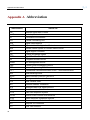
1
USER'S MANUAL VoIP Gateway Venus 2814 Headquarters: No. 25, Alley 15, Lane 120, SEC. 1. NEI-HU RD, Taipei 114, Taiwan TEL: 886-2-26583000 FAX: 886-2-26583232 Beijing Branch: 3F, A Building, 113 Zhi Chun Lu, HaiDian District, Beijing, China Zip Code: 100086 TEL: 86-10-62522081~87 FAX: 86-10-62522077 Version: 1.0 Date: 2009/12/10 P/N: 07008-00133 Venus 2814 User’s Manual Copyright © 2009 TAINET COMMUNICATION SYSTEM CORP. All rights reserved Notice This document is protected by the international copyright law. No part of this publication may be reproduced by any means without the expressed permission of Tainet Communication System Corporation. TAINET is a registered trademark, and Venus 2814 SIP is a trademark of Tainet Communication System Corporation. Other product names mentioned in this manual are used for identification purposes only and may be trademarks or trademarks of their respective companies. The information provided from Tainet Communication System Corporation is believed to be accurate. Any changes and enhancements to the product and to the information thereof will be documented and issued as a new release to this manual. Trademark All products and services mentioned herein are the trademarks, service marks, registered trademarks or registered service marks of their respective owners. i Venus 2814 User’s Manual About This Manual This manual includes installation, testing and management sections of VENUS 2814.The summary is as below: Chapter 1: Introduction Chapter 2: Hardware Installation Chapter 3: Device Management via WEB Chapter 4: Maintenance and Troubleshooting Appendix A: Abbreviation ii Venus 2814 User’s Manual Symbols Used in This Manual 3 types of symbols may be used throughout this manual. These symbols are used to advise the users when a special condition arises, such as a safety or operational hazard, or to present extra information to the users. These symbols are explained below: Warning: This symbol and associated text are used when death or injury to the user may result if operating instructions are not followed properly. Caution: This symbol and associated text are used when damages to the equipment or impact to the operation may result if operating instructions are not followed properly. Note: This symbol and associated text are used to provide the users with extra information that may be helpful when following the main instructions in this manual. iii Venus 2814 User’s Manual LIMITED WARRANTY TAINET’s DISTRIBUTOR shall be responsible to its customers for any and all warranties, which it makes relating to Products, and for ensuring that replacements and other adjustments required in connection with the said warranties are satisfactory. TAINET warrants to DISTRIBUTOR that the Products to be delivered hereunder will be free of defects in material and workmanship under normal use and service for a period of twenty-four (24) months [twelve (12) months in Taiwan] following the date of shipment to DISTRIBUTOR. If during the warranty period, any component part of the equipment becomes defective by reason of material or workmanship, and DISTRIBUTOR notifies TAINET of such defect within seven days after knowing of such defect, TAINET shall, for any Product that TAINET agrees is defective, at its option, supply a replacement part, request return of equipment to its plant for repair, or perform necessary repair at the equipment’s location. At TAINET's option, DISTRIBUTOR shall destroy any Product that TAINET agrees is defective and shall provide satisfactory proof of such destruction to TAINET. TAINET is not responsible for Products damaged by misuse, neglect, accident or improper installation, or if repairs or modifications were made by persons other than TAINET’s own authorized service personnel, unless such repairs by others were made with the written consent of TAINET. THE ABOVE WARRANTY IS IN LIEU OF ALL OTHER WARRANTIES, EXPRESSED OR IMPLIED. THERE ARE NO WARRANTIES THAT EXTEND BEYOND THE FACE HEREOF, INCLUDING, BUT NOT LIMITED TO, WARRANTIES OF MERCHANTABILITY AND FITNESS FOR A PARTICULAR PURPOSE, AND IN NO EVENT SHALL TAINET BE LIABLE FOR CONSEQUENTIAL DAMAGES. If DISTRIBUTOR extends to its customers any additional warranty with respect to Products that is broader in scope than the warranty provided by TAINET, DISTRIBUTOR shall be solely responsible for any and all liabilities, obligations and damages resulting from the extension of such warranty. TAINET shall not be liable to any person for any special or indirect damages, including, but not limited to, lost profits, from any cause whatsoever arising from or in any way connected with the manufacture, sale, handling, repair, maintenance or use of the Products, and in no event shall TAINET’s liability exceed the purchase price of the Products. iv Venus 2814 User’s Manual Software Products are provided “as is” and without warranty of any kind. TAINET disclaims all warranties including the implied warranties of merchantability and fitness for a particular purpose. TAINET shall not be liable for any loss of use, interruption of business or indirect, special, incidental or consequential damages of any kind. TAINET shall do its best to provide end users with Software updates during the warranty period under this Agreement. TAINET has not been notified of any intellectual property rights or others which may be infringed by the Products or the promotion, marketing, sale (or resale), or servicing thereof in the Territory, but TAINET makes NO WARRANTY, EXPRESS OR IMPLIED, WITH RESPECT THERETO. v Venus 2814 User’s Manual CONTENTS CHAPTER 1. INTRODUCTION ............................................................................... 1 1.1 1.2 1.3 INTRODUCTION .......................................................................................................................... 1 APPLICATIONS ........................................................................................................................... 1 PRODUCT DESCRIPTION ............................................................................................................. 5 1.3.1 Hardware Architecture .......................................................................................................................5 1.3.2 Management .......................................................................................................................................6 1.4 TECHNICAL SPECIFICATIONS ..................................................................................................... 8 CHAPTER 2. HARDWARE INSTALLATION ...................................................... 11 2.1 2.2 UNPACKING ............................................................................................................................. 11 SITE REQUIREMENTS ............................................................................................................... 12 2.2.1 Site Selection....................................................................................................................................12 2.2.2 AC Electrical Outlet Connection......................................................................................................12 2.2.3 Grounding ........................................................................................................................................12 LED INDICATORS .................................................................................................................... 14 FRONT PANEL CONNECTIONS .................................................................................................. 15 2.4.1 Connecting the IP Network via Ethernet..........................................................................................15 2.4.2 Connecting the Terminal ..................................................................................................................15 2.3 2.4 2.5 2.6 2.7 2.8 2.9 POWER SOURCE CONNECTION ................................................................................................. 17 VOICE CONNECTION ................................................................................................................ 17 DATA CONNECTION ................................................................................................................. 18 HARDWARE DIAGNOSIS ........................................................................................................... 19 BASIC CONFIGURATION ........................................................................................................... 20 CHAPTER 3. WEB MANAGEMENT..................................................................... 21 WEB MANAGEMENT............................................................................................................... 21 3.1.1 Setup PC...........................................................................................................................................21 3.1.2 Login ................................................................................................................................................21 3.1 3.2 CONFIGURATIONS .................................................................................................................... 22 3.2.1 General Configurations ....................................................................................................................22 3.2.2 EM Configuration ............................................................................................................................22 3.2.3 Conference Group ............................................................................................................................23 3.3 SYSTEM STATUS ...................................................................................................................... 25 3.3.1 H/W Info ..........................................................................................................................................25 3.3.2 System Info ......................................................................................................................................25 vi Venus 2814 User’s Manual 3.4 SYSTEM OPERATION ................................................................................................................ 26 3.4.1 Warm Start........................................................................................................................................26 3.4.2 Restore Default................................................................................................................................. 26 3.4.3 Software Upgrade.............................................................................................................................28 CHAPTER 4. MAINTENANCE AND TROUBLESHOOTING........................... 29 4.1 4.2 INSTRUMENTS ......................................................................................................................... 29 TROUBLESHOOTING................................................................................................................. 30 APPENDIX A ABBREVIATION .............................................................................. 33 vii Venus 2814 User’s Manual FIGURES Figure 1-1 The Front View of VENUS 2814 ................................................................................5 Figure 1-2 The Rear View of VENUS 2814.................................................................................5 Figure 2-1 DB-9F Console Interface .........................................................................................16 Figure 2-2 Voice Interface .........................................................................................................17 viii Venus 2814 User’s Manual TABLES Table 1-1 VENUS 2814 Technical Specification ........................................................................8 Table 2-1 LED Description.......................................................................................................14 Table 2-2 10/100Base-T Connection .......................................................................................15 Table 2-3 Pin definition of the Console Port connector............................................................16 Table 2-1 Pin assignments for the voice interface ........................................................................17 Table 2-2 Data port pin assignment ..............................................................................................18 Table 3-1 General configuration descriptions ...............................................................................22 Table 3-2 EM configuration descriptions.......................................................................................23 Figure 3-7 Restore default............................................................................................................27 Table 3-3 Software upgrade .........................................................................................................28 Table 4-1 ix Voice Codec Bandwidth...........................................................................................32 Chapter 1 Introduction Chapter 1. Introduction 1.1 Introduction VENUS 2814 is designed for wireless phone systems using wired links wireless devices to make broadcast calls. In a traditional wireless link system, the user needs to set up multiple repeater units, in order to increase the coverage area, or to overcome the effects of terrain. There are a few disadvantages, including: high cost, too many sites, the need to manually deploying the same multicast group, difficult maintenance, and limited distance. When there are too many hops, it will result in lower signal to noise ratio, and the actual coverage is limited. VENUS 2814 can convert the conventional radio relay link to wired relay link, to overcome the shortcomings of traditional wireless relay: Each channel only need to configure a machine controller, equipment cost is lower; The same multicast group scheduler operates completely at the center nodes, with automatic remote operation; Transmission distance is not limited to a region, and only uses one hop; Wired relay can save frequency resources; Point-to-point conference, multi-point conference and mix frquency calling through software configuration. VENUS 2814 can achieve all the above functions, only with the cost of IP network. 1.2 Applications Point-to-point application. Wireless call via IP network, point-to-point application. 1 Chapter 1 Introduction Figure 1-1 Point-to-point application Multi-point application When two distant regions are subject to topographical constraints, and need to broadcast the same call, they can configure two separate VENUS 2814, used in conjunction with the channel machines. The channel A machine within the coverage area of the radio, can call the channel machine B radio stations within the coverage area. This is a Multi-point application. 2 Chapter 1 Introduction Figure 1-2 Multicast application When more than one network regions have calling tasks, each channel machine under the VENUS 2814 with the monitoring center server on the same broadcast network, with the help of the broadcast server, the radio stations covered by the channel machine A / B / C within the coverage area, can call each other. Mix frequency call application 3 Chapter 1 Introduction Figure 1-3 4 Mix frequency call application When different frequency channel machines have a mix frequency call demand, the channel can be connected to different ports on the same VENUS 2814, or different VENUS 2814 device. After software configuration, the mix frequency call can be achieved; different radio frequency bands can call each other through the VENUS 2814. Chapter 1 Introduction 1.3 Product Description 1.3.1 Hardware Architecture VENUS 2814 is a rack-mount, standard 19-inch wide, 1U high chassis device. As shown in Figure 1-4: the front panel of VENUS 2814 includes a serial CON port, a reset button, and a 2814 of LED indicators. Figure 1-1 The Front View of VENUS 2814 WAN port Console port Reset switch WAN status LED DATA (downstream) status LED System LED Voice channel LED Power LED Figure 1-2 The Rear View of VENUS 2814 Power outlet Reserved DATA port Voice channel for connecting to relays 5 Chapter 1 Introduction Reserved phone ports 1.3.2 Management VENUS 2814 provides several different ways for equipment management: 1.3.2.1 Terminal User Interface via the Console port for local management Terminal User Interface via Telnet for remote management Terminal User Interface via Web browser for remote management SNMP Management Console Port By using the VT-100/ANSI compatible terminal emulation software, such as Microsoft HyperTerminal, user is able to configure VENUS 2814 via the Console port at the front panel. Refer to Chapter 3 for detailed Terminal UI description. 1.3.2.2 Telnet VENUS 2814 can be managed through a Telnet connection. The User Interface format and the management functions provided by TELNET are exactly the same as the console port. To maintain the consistency of configuration, only one single user is allowed to login the terminal user interface via the console port or Telnet at the same time. 1.3.2.3 Web Browser The gateway allows users to make settings using a web browser, must enable Web function of the Venus configuration item first. After opening a browser, enter gateway’s IP address as the website address in order to enter the Web configuration screen as shown in the following diagram. (IE Browser used for example) Please refer to Chapter 3. 6 Chapter 1 Introduction 1.3.2.4 SNMP Management The embedded SNMP agent in VENUS 2814 allows the device to be managed by the SNMP management system. 7 Chapter 1 Introduction 1.4 Technical Specifications Table 1-1 VENUS 2814 Technical Specification Items General Specification Number of supported voice channels: 4 Console port: RS-232, DCE mod, interface: DB-9, female WAN port: IEEE 802.3u 10/100Base-T Fast Ethernet LED: PWR, RUN, WAN, DATA, VOICE CHANNEL 1~4 Button: RESET Power: AC 100V ~ 230VAC, 50~60 Hz Interface:DB 9, female 2-wire interface: (follow ITU-T G.712) Impedance: 600Ω or 900Ω, configurable Return loss: 300Hz ~ 600Hz >12dB, 600Hz ~ 3400Hz >15dB Input gain: 0 to –5 dBm, adjustable (default-7dBm) Output gain: -2 to –8 dBm, adjustable (default-2dBm) Voice channel Attenuation/frequency offset: Figure 5/G.712 Idle noise: < -65 dBm0p 4-wire interface: (follow ITU-T G.712) Impedance: 600Ω Input gain: -14 ~ +3 dBm, adjustable (default -7dBm) Output gain: -13 ~ +4 dBm, adjustable (default -2dBm) Attenuation/frequency offset: Figure 4/G.712 Idle noise: < -65 dBm0p Data port: RS-232, DCE mode, interface: DB-9, male Data rate: 1.200-230.400Kbps Data port Data format: 1 start bit,7 or 8 data bits, 1, 1.5 or 2 stop bits Support checksum: None, even, odd, Mark, Space Flow control: none Console Management Telnet Web/HTTP SNMP 8 Chapter 1 Introduction Items Specification Working temperature: 0°C ~ 50°C Working environment Storage temperature: -10°C ~ 70°C Relative humidity: 10% ~ 90% (non-condensing) Size 9 437 W x 44 H x 286 D mm 19” 1U Pizza Box Chapter 2 Hardware Installation Chapter 2. Hardware Installation 2.1 Unpacking This chapter provides the information for installation of the VENUS 2814. Before unpacking, make a preliminary inspection of the container. Evidence of damage should be noted and reported immediately. Unpack the equipment as follows: Place the container on a flat surface and open the container. Carefully take the VENUS 2814 out of the container and place it securely on a flat, clean surface. Inspect the unit for signs of damage. Immediately report any damage found. Check the packing list against your order to ensure that the supplied modules match your order. If modules have been pre-installed in accordance with your order, check that all the modules are in their proper slots and are secure. Immediately report any deviations. 11 Chapter 2 Hardware Installation 2.2 Site Requirements 2.2.1 Site Selection Install the device in a clean area that is free from environmental extremes. Allow at least 6 inch (15.24 cm) in front of the device for access to the front panel, and at least 4-inch (10.2 cm) in back for cable clearance. Position the device so you can easily see the front panel. 2.2.2 AC Electrical Outlet Connection VENUS 2814 with AC power input should be installed within 1.83m (6 feet) of an easily accessible grounded AC outlet capable of furnishing the required supply voltage, in the range of 100 to 230V AC. 2.2.3 Grounding The FCC requires telecommunications equipment to withstand electrical surges that may result from lightning strikes; the VENUS 2814 device meet the requirements set forth by the FCC. The following procedure outlines some common practices that can minimize the risk of damage to computer equipment from electrical surges. Make sure the electric service in your building is properly grounded as described in article 250 of the National Electrical Code (NEC) handbook. Verify that a good copper wire of the appropriate gauge, as described in Tables 250-94/95 of the NEC Handbook, is permanently connected between the electric service panel in the building and a proper grounding device such as: 12 A ground rod buried outside the building at least 8 feet (2.44 meters) deep in the earth. Chapter 2 Hardware Installation Several ground rods, connected together, buried outside the building at least 8 feet (2.44 meters) deep in the earth. A wire (see tables 250-94/95 of the NEC handbook for gauge) that surrounds the outside of the building and is buried at least 2.5 feet (.76 meters) deep in the earth. Note: The three grounding devices described above should be firmly placed in the earth. Soil conditions should not be dry where the device is buried. 13 If you are unsure whether the electric service in your building is properly grounded, have it examined by your municipal electrical inspector. Install a surge protector between the device and Ground point. Any additional computer equipment you have connected to the device (directly or through another device), such as a terminal or printer should also be plugged into the same surge protector. Make sure that the surge protector is properly rated for the devices you have connected to it. Call your telephone company and ask them if your telephone line is equipped with a circuit surge protector. If you are operating the device in an area where the risk of electrical surges form lightning is high, disconnect the device from the telephone line at the rear panel when it is not in use. Chapter 2 Hardware Installation 2.3 LED Indicators Table 2-1 Label PWR LED Description Function Description Power Status Colors Off (Power is Off) Green (Power is ON) Green (Normal Operation) RUN System Status Yellow (Performing Diagnosis) Red (System Failure) VOICE CHANNEL WAN Voice Channel Off (On-Hook State of the Telephone Handset) Status Green (Off-Hook State of the Telephone Handset) WAN Status Green (Network Card is plug in and 10/100 Base-T Link is Up) Off (Network Card is unplug) Off (Link failure) DATA Data Status Green (Link is up) Blinking (Working) 14 Chapter 2 Hardware Installation 2.4 Front Panel Connections 2.4.1 Connecting the IP Network via Ethernet On the base unit of VENUS 2814, the embedded 10/100Base-T Ethernet port is provided as the standard interface to the IP network. The pin layout of the RJ-45 connector for IEEE 802.3 standard 10/100Base-T Ethernet ports are defined as following: Table 2-2 10/100Base-T Connection Pin #. Pin Function 1 TD+ 2 TD- 3 RD+ 4 N/C 5 N/C 6 RD- 7 N/C 8 N/C For connecting the 10/100Base-T Fast Ethernet, a Category 5 unshielded twisted-pair (UTP) cable or shielded twisted-pair cable is used. Two pairs of the twisted wires are used for separated Rx (reception) and Tx (transmission). The Fast Ethernet port is backward compatible with traditional 10Base-T Ethernet. VENUS 2814 can automatically detect whether it is connected to a 10Base-T or 100Base-T Network. 2.4.2 Connecting the Terminal The Console port connector labeled “CRAFT” on the front panel is provided for connection to an external ANSI or VT-100 compatible terminal for quick and easy, local configuration of the VENUS 2814. 15 Chapter 2 Hardware Installation Speed and Data format: 115,200bps, none parity, 8 data bits, 1 stop bit, and no flow control. Figure 2-1 DB-9F Console Interface The console interface designed on VENUS 2814 is a female, DCE type RS-232 port. A straight DB-9 to DB-9 or DB-9 to DB-25 serial cable can be used to connect VENUS 2814 directly to a PC’s serial port for terminal operation. The PIN definition of the DB-9 is: Table 2-3 Pin # Pin definition of the Console Port connector Signal Source 2 TXD (Transmit Data) DCE 3 RXD (Receive Data) DTE 5 Signal Ground 7 CTS (Clear To Send) DTE 8 RTS (Request To Send) DCE Note: The serial UART port on some of the PCs may not support or guarantee the speed of 115,200bps. Try another PC if the terminal program is not responding or is displaying incorrect characters. 16 Chapter 2 Hardware Installation 2.5 Power Source Connection This model supports 100V~230VAC/50~60Hz (Auto-range) power source. Note: It is strongly recommended to use an AC power cord with Grounding pin or connect the Grounding Screw on the rear panel to the grounded supply of correct power system at the site. 2.6 Voice Connection VENUS 2814 device supports 4 voice ports, which can be connected with the channel machine port. The connection interface is DB-9, female. Figure 2-3 shows the pin assignments. Figure 2-2 Voice Interface Table 2-1 Pin assignments for the voice interface pin # Signal 1 Tipn (Receive voice) 2 3 4 5 6 7 8 Source Channel machine TipnA (Transmit voice) VENUS 2814 M Channel machine E VENUS 2814 Ringn Channel machine RingnA VENUS 2814 Gnd Reserved Data Connection VENUS 2814 device supports 4 voice ports, which can be connected with the channel machine port. The connection interface is DB-9, female. Figure 2-3 shows the pin assignments. 17 Chapter 2 Hardware Installation 2.7 Data Connection Data Connection VENUS 2814 device supports 4 voice ports, which can be connected with the channel machine port. The connection interface is DB-9, female. Figure 2-3 shows the pin assignments. Figure 2-1 Table 2-2 Pin # 2 3 5 7 8 18 Data port Data port pin assignment Signal TXD (Transmit data) RXD (Receive data) Signal ground CTS (Clear to send) RTS (Request to send) Source DCE DTE DTE DCE Chapter 2 Hardware Installation 2.8 Hardware Diagnosis When all cable connection are completed, turn on the device power, the software will be loaded automatically. VENUS 2814 will perform hardware detection, initialization and diagnostics. The progress of hardware diagnostics is displayed by the front panel LED indicators. If all the hardware tests are passed, "RUN" indicator will be green. If it is red, this indicates that the hardware is faulty. For the results of hardware diagnosis, please see the messages displayed on the terminal program. 19 Chapter 2 Hardware Installation 2.9 Basic Configuration After VENUS 2814 successfully boots up, the user can configure the device via WEB or Console. Default WEB login IP address is 192.168.0.1, mask is 255.255.255.0. All ports of the same multicast controller need to be assigned numbers in advance by the network management center; When using Multi-point multicast, all multicast controllers need to assign with the same multicast number. The multicast numbers are set on the broadcast server must be allocated by the network management center in advance. Above configurations can be found in the user management interface (UI). 20 Chapter 3 WEB Management Chapter 3. WEB Management This chapter describes VENUS 2814 user interface (UI). There are two ways to access the device: through the serial CON port or via WEB. WEB interface are for end users, and CON can manage more parameters, available for advanced users. If the assigned IP address is correct, the user can login to TUI via WEB or Telnet. Section 3.1 describes WEB management. 3.1 WEB Management 3.1.1 Setup PC When using WEB to manage VENUS 2814, first setup the IP address of the computer (terminal device), ensure the PC can access VENUS 2814. 3.1.2 Login Open the web browser, such as Microsoft's IE browser, and type in the address bar with VENUS 2814's IP address. Default VENUS 2814 IP address is 192.168.0.1, with mask 255.255.255.0. Default user name and password are both admin. 21 Chapter 3 WEB Management 3.2 Configurations 3.2.1 General Configurations Figure 3-1 shows the terminal interface. Table 3 1 shows the available menu options. Figure 3-1 Table 3-1 Item General configurations General configuration descriptions Description To enter a name for the VENUS 2814 device for IAD Name easier management. Do not input Chinese. IP address Set the IP address of VENUS 2814 Net Mask Set the netmask of VENUS 2814 Default Gateway Set the default gateway of VENUS 2814 3.2.2 EM Configuration In the EM configuration page, the number, hotline and method of each ports is assigned. As show in Figure 3-2. 22 Chapter 3 WEB Management Figure 3-2 Table 3-2 Item Port Number Hotline Mode 3.2.3 EM configuration EM configuration descriptions Description Port 1~4 represents the 4 voice channel of VENUS 2814 Assign a unique number for the voice port. Needs to be assigned by the network management center. 1、 When used in point-to-point application, set the voice link to VENUS 2814 message with the format "to voice channel number@to IP address of VENUS 2814"; 2、 When used in multicast application, set the multicast server message with the format "multicast number@multicast server IP address". Select operating mode for point-to-point or multipoint multicast. Conference Group In the conference group page, the each port can be assigned with a conference group. Every group can have up to 32 multicast points or broadcast channels. The conference group format is "other port numbers that belong to the same group@multicast server IP address". When making conference calls, local port should follow the list in the conference table to send message to the remote units. 23 Chapter 3 WEB Management Figure 3-3 Conference group When working in multipoint conference mode, first enter the conference server number and IP address in the "link setup-link number" field. Next enter the other ports in the same conference group in the "conference group list" field. Select Port1~Port4 conference group in this page to show/edit the other ports in the same group, the format is "port number@conference server IP address". 24 Chapter 3 WEB Management 3.3 System Status This menu displays the status of VENUS 2814. 3.3.1 H/W Info Shows the hardware configuration and diagnosis report of VENUS 2814. Figure 3-4 3.3.2 H/W info System Info Display system up time of VENUS 2814 and other information. Figure 3-5 25 System info Chapter 3 WEB Management 3.4 System Operation This menu performs the following functions: reboot, restore to default and software upgrade of VENUS 2814. 3.4.1 Warm Start VENUS 2814 needs 50 seconds to perform warm start. The network will be down during rebooting. Figure 3-6 3.4.2 Warm start Restore Default Operate VENUS 2814 to restore to factory settings and restart, but IP addresses will stay unchanged. Link will be interrupted during rebooting. After restored to default, VENUS 2814 keeps the IP address unchanged, thus the other parameters need to be reconfigured. The default parameters are below: IAD name: MAC Mode: P2P Port number: 01~04 26 Chapter 3 WEB Management Link number: blank Multilink group list: blank Figure 3-7 27 Restore default Chapter 3 WEB Management 3.4.3 Software Upgrade Software upgrade time depends on network condition. The link will be interrupted during the upgrade. VENUS 2814 supports upgrading with TFTP. Table 3-3 Item TFTP server IP address TFTP server port Binary file name Figure 3-8 28 Software upgrade Description Enter IP address of the TFTP server. Enter TFTP server port, usually 69. Enter file name of the software, must include the extension. Software upgrade Chapter 4 Maintenance and Troubleshooting Chapter 4. Maintenance and Troubleshooting 4.1 Instruments The following instruments may help to allocate the problem: 29 A multi-meter: to identify the line condition, the power condition, etc. A PC: with a LAN card installed and the IP setup configured properly A network scope: to identify the network status and the traffic load over the network. Chapter 4 Maintenance and Troubleshooting 4.2 Troubleshooting Turn off the power first. Follow the procedures below to allocate the problem: 1) Cable Connections Make sure all the cables are connected correctly and firmly. Check if you provide a correct power source. 2) The Power Source The LED indicators offer some helpful information for users to check the hardware status of VENUS 2814. Check if the PWR LED is ON. Use the multi-meter to measure the power supply. 3) Boot up Diagnosis Observe the boot up sequence of the gateway. During the boot up phase, VENUS 2814 performs the hardware initialization, run-time AP software verification, interface module detection and then the hardware diagnosis procedure. Check if all the LEDs can display correctly. The SYS ALM LED indicates the diagnosis state: while it is Yellow, the device is performing diagnosis. A Red SYS ALM LED indicates a hardware failure. A Green SYS LED indicates no hardware failure. Login to the Craft port Interface, and select the “Hardware Configuration and Diagnosis Report” menu to see if the device reports correct hardware configuration, type of interface cards installed, number of voice channel detected, and the diagnosis results. In case of hardware failures, record the indication of LEDs during the boot up phase, and report the diagnosis result generated by VENUS 2814 to our customer service. 4) IP Network Interface Connection Check the indicator for the WAN interface indicating normal condition. If the 10/100Base-T Fast Ethernet port is used, check if the 10/100BT LED is on. Verify if a correct Ethernet cable is used. To connect VENUS 2814 directly to another Ethernet port of a network node (for example a router), a cross cable, instead of a straight cable, may be used. 30 Chapter 4 Maintenance and Troubleshooting 5) IP Address Configuration Check if the IP address was assigned statically or obtained dynamically from a DHCP server. If the DHCP client mode is enabled, look at the DHCP server for the exact IP address assigned to the gateway or monitor the display message of the DHCP server discovery status from the Terminal User Interface via the Console port. Remember that the DHCP server must be located in the local network where the DHCP server can receive the broadcast packets sent from the gateway. Make sure there is unused IP address available on the DHCP server. If static IP address is enabled, make sure the net mask and the default Gateway are set correctly. Use the PC to perform a PING test to the gateway, or activate the PING feature from within the Craft port Interface to verify the IP packet transmission between the gateway and some other nodes. Try to PING the default gateway first, then the SIP Proxy Server. Check with your access service provider for a well-maintained WAN link. Use the Network Scope (or the Protocol Analyzer) to monitor the packets sent received by the VENUS 2814. 6) Firewall and NAT Normally, a public IP address should be used for VENUS 2814. In case the VENUS 2814 is located in the local network behind the firewall or router, Make sure the IP packets is not blocked or modified. For the security purpose, a firewall server or VPN is usually installed to filter out unauthorized accesses from the outside world. Make sure the traffic to/from the VoIP gateway is not blocked. The NAT server may cause problem as well. The NAT server performs the Network Address Translation between the public IP address and the private IP address. It may not recognize some Text-based protocols (like SIP) used by the VoIP gateway and may cause incorrect IP address or port translation for a packet. 7) Hear the Voice Quality If the voice quality is not good, possible reasons include Low WAN link throughput not able to support enough bandwidth for voice traffic (see the following table for calculation of maximum bandwidth required) Network congestion: a well maintained network flow control policy or protocol 31 Chapter 4 Maintenance and Troubleshooting help to control the traffic and prioritize the service for different type of media Network device delay: firewall, router, switch, access device, etc all contribute latency to the traffic. A good network configuration in advance is very important. Type of the Voice Codec selected is a big factor and tradeoff to the voice quality. The PCM type codec (G.711 u-law or A-law) provide excellent voice quality, but consume large amount of network bandwidth. A higher compression rate codec provide fair voice quality and consumes less network bandwidth, however requires more CPU/DSP power which increase the voice latency. Table 4-1 Voice Codec Bandwidth Codec Types 32 Bit Rate ITU-T G.711 A-Law PCM 64K ITU-T G.711 μ-Law PCM 64K ITU-T G.723.1 6.3K/5.3K ITU-T G.729A 8K ITU-T G.726. 16/24/32/40K Appendix A Abbreviation Appendix A Abbreviation Abbreviation Stands for ARP Address Resolution Protocol BootP Bootstrap Protocol CLI Command Line Interface CPU Central Processing Unit DDN Digital Data Network DHCP Dynamic Host Configuration Protocol DNS Domain Name System or Domain Name Server DSP Digital Signal Processor FXS Foreign Exchange Station HTTP Hyper Text Transfer Protocol IAD Integrated Access Device IADMS IAD Management Server ICMP Internet Control Message Protocol IETF Internet Engineering Task Force ITU-T International Telecommunication Union - Telecommunication MDU Multi-Dwellings Units MGCP MEDIA GATEWAY CONTROL PROTOCOL MIB Management Information Base MTU Multi-Tenants Units NAT Network Address Translation NCS Network-based Call Signal protocol NGN Next Generation Network POTS Plain Old Telephone System PPPoE Point-to-Point Protocol over Ethernet PSTN Public Switched Telephone Network RARP Reverse Address Resolution Protocol RFC Request for Comments RTP Real Time Protocol 33 Appendix A Abbreviation SDP Session Description Protocol SIP Session Initiation Protocol SNMP Simple Network Management Protocol TCP Transmission Control Protocol TELNET Telecommunication Network Protocol TFTP Trivial File Transfer Protocol UA User Agent UI User Interface UDP User Datagram Protocol URL Uniform Resource Locator VAD Voice Activity Detection VoIP Voice over Internet Protocol VPN Virtual Private Network 34