1
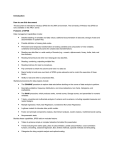
OASIS User Manual
OASIS™ 1.0
(Open Architecture Software
Integration System - SBIR Phase II
Development Version)
User Manual:
Building Application Modules for the
Particle Beam Optics Laboratory
(PBO Lab™)
Prepared by
G. H. Gillespie Associates, Inc.
P. O. Box 2961
Del Mar, CA 92014
(Phone 858-677-0076)
Prepared as part of the work completed under
U.S. Department of Energy
Small Business Innovative Research grant number
DE-FG02-04ER83961
Included as an Appendix to the Final Report
GHGA-08-645-R on the above referenced grant.
i
OASIS User Manual
OASIS 1.0 (prerelease) User Manual: Building Application Modules for PBO Lab™
2005-2008 by G. H. Gillespie Associates, Inc.
All Rights Reserved.
First Printing: [to be determined in Phase III]
ISBN [to be assigned in Phase III]
All rights reserved. No part of this book may be
reproduced, in any form or by any means, without
permission from the publisher.
Printed in the United States of America.
[In Phase III, to be Published by AccelSoft Inc., San Diego, California.]
ii
OASIS User Manual
Table of Contents
Section and Subject
Page
1. Introduction ...............................................................................................................1
Overview...............................................................................................................3
Installing OASIS ..................................................................................................4
Initial Set Up ........................................................................................................6
2. Defining an OASIS Application Module (OModule) ...............................................9
OASIS Module Specification ............................................................................11
Module File I/O Specification ...........................................................................13
Global Parameter Selection ...............................................................................15
Header Syntax for the Main Input File .............................................................20
3. Beamline (Lattice) Parameters & Syntax ...............................................................27
Optical Components ..........................................................................................29
Example Using a Drift Piece ........................................................................29
Drift Syntax for Different Computation Engines ....................................37
Example for a Quadrupole Piece ..................................................................41
Example for Logical-Parameter Switch .................................................45
If-EndIf and IfNot-EndIf Runtime Variables ..........................................48
Quadrupole Examples for Different Computation Engines ....................51
Sequence Runtime Variables ..................................................................53
Other Components ..............................................................................................57
Beam Piece ...................................................................................................57
Beam Correlations ...................................................................................59
Example for Parameter-Group Switch ...................................................63
Centroid, Current, Energy Tab Panel ......................................................68
Marker Piece .................................................................................................69
PBO Lab Parameter Piece ............................................................................73
Special (SPEC) Parameter Piece ..................................................................75
Summary of PBO Lab Pieces Supported by OASIS .........................................78
4. Other Input Parameters & Syntax ...........................................................................79
Command Piece Specification ...........................................................................81
A Simple Comm Piece Specification ............................................................86
Some Other Comm Piece Specifications.......................................................90
iii
OASIS User Manual
Special Parameter Settings (SPS) .......................................................................95
Matrix Special Settings ......................................................................................98
Lines and Sublines Specification......................................................................100
Custom Parameter Piece Specification.............................................................109
Custom Optics Piece Specification...................................................................115
Wien Filter Example for PSI-TRANSPORT ..............................................115
What the PSI-TRANSPORT OModule User Sees for the Wien Filter ......122
Alias Piece & Alias Subline Specification ......................................................125
Undefined Piece Specification .........................................................................127
OASIS Module (OModule) Options ................................................................130
Final (Footer) Section .......................................................................................139
5. Utilizing PBO Lab Tools ......................................................................................141
Overview of PBO Lab Tools ...........................................................................143
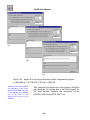
PBO Lab Plot Tools .........................................................................................144
Step 1 - Plot Data Specification...................................................................144
Step 2 - Linking Plot Specs to Data Files ...................................................153
Optimizer Integration .......................................................................................159
Optimizer Vary Parameters .........................................................................159
Optimizer Storage Parameters .....................................................................160
iv
OASIS User Manual
List of Principal Figures
Figure Number and Abbreviated Caption
Page
Section 1 - Introduction
Figure 1. OASIS is used to create Application Modules for PBO Lab ..........................4
Figure 2. PBO Lab Document Window .........................................................................5
Figure 3. In the PBO-Lab Preferences window, select the OASIS Module Builder .....6
Figure 4. The OASIS Module Builder window .............................................................7
Figure 5. OASIS Module Specification Document window & Commands menu ........8
Section 2 - Defining an OASIS Application Module (OModule)
Figure 6. OASIS Module Information window ...........................................................11
Figure 7. An OASIS Module About window ..............................................................12
Figure 8. File I/O Specification window .....................................................................13
Figure 9. Globals parameter selection window ............................................................15
Figure 10. SPS window for Beam Energy Global Parameter ......................................16
Figure 11. Globals parameter selection window for DIMAD-sample OModule ........20
Figure 12. Input Syntax for Globals window ...............................................................21
Figure 13. Syntax for Header as specified for the DIMAD-sample OModule ............24
Figure 14. Input Syntax for Globals window after Update .........................................25
Figure 15. Header Section of the Main Input File .......................................................26
Section 3 - Beamline (Lattice) Parameters & Syntax
Figure 16. OASIS Module Specification Document with Drift Piece ........................30
Figure 17. Drift Piece window with selected features identified..................................30
Figure 18. Special Parameter Settings (SPS) window for Effective Drift Length ......31
Figure 19. SPS Window when the OModule parameter selection box is checked .....32
Figure 20. Input Syntax for Drift Space window for DIMAD ....................................33
Figure 21. Input Syntax for Drift Space window after Update ....................................35
Figure 22. Input Syntax for Drift Space for (a) PARMILA-1, (b) PARMILA-2
and (c) "old" style TRANSPORT.......................................................................38
Figure 23. Input Syntax for Drift Space for (a) "MAD" style TRANSPORT,
(b) TRACE 3-D and (c) MARYLIE...................................................................39
Figure 24. Quadrupole Piece window for the DIMAD-sample OModule ..................41
v
OASIS User Manual
Figure 25. Input Syntax for Quad window for the DIMAD-sample OModule ...........43
Figure 26. Fringe Field tab panel with two logical-parameter switches ......................45
Figure 27. Special Parameter Settings (SPS) window for logical-parameter switch ...46
Figure 28. Input Syntax for Quadrupole window for PSI-TRANSPORT ...................49
Figure 29. Another Input Syntax for Quad for PSI-TRANSPORT OModule ............50
Figure 30. Input Syntax for Quadrupole for (a) PARMILA-1, (b) PARMILA-2
and (c) TRACE 3-D ...........................................................................................52
Figure 31. PBO Lab physical and unphysical Pieces for Sequence variable ...............54
Figure 32. Physical and unphysical OASIS Pieces for Sequence variable ................54
Figure 33. Input Syntax for Quadrupole using Sequence and Sequence++
runtime variables for a TRACE 3-D OModule .................................................55
Figure 34. Beam Piece window with parameter-group switch set to Semi-Axes .......57
Figure 35. Correlation Matrix window opened from the Beam Piece window ...........59
Figure 36. Special Settings window to select individual matrix elements ..................60
Figure 37. SPS window for the correlation matrix element r(2,1) ..............................60
Figure 38. Input Syntax for Initial Beam for the “old" style TRANSPORT ...............61
Figure 39. Beam Piece window with parameter-group switch set to
(a) Semi-Axes - Beam 1 and (b) Courant-Snyder (Twiss) - Beam 2 ................63
Figure 40. SPS window for the Beam Parameters parameter-group switch ................64
Figure 41. Syntax Specification for a DIMAD OModule using Semi-Axes................65
Figure 42. Syntax Specification for a DIMAD OModule using Twiss .......................67
Figure 43. Centroid, Current, Energy tab panel of the Beam Piece window ...............68
Figure 44. Marker Piece window .................................................................................69
Figure 45. The automatic functionality of a default Marker Piece ..............................71
Figure 46. Input Syntax for Marker window ...............................................................72
Figure 47. PBO Lab Parameter Piece window .............................................................73
Figure 48. Input Syntax for Parameter Piece window .................................................74
Figure 49. Special (SPEC) Piece window ....................................................................75
Figure 50. An Input Syntax for Special (SPEC) window ............................................76
Figure 51. Bend Fringes of SPEC Piece with 4 parameters for PSI-TRANSPORT ....77
Figure 52. Input Syntax for Special window ...............................................................77
Figure 53. PBO Lab Pieces that are Supported by OASIS ..........................................78
Section 4 - Other Input Parameters & Syntax
Figure 54. OASIS Command Piece Specification name window ...............................82
Figure 55. OASIS Module Specification Document with OASIS Comm Piece .........82
Figure 56. Command Specification window ...............................................................83
Figure 57. Define Arguments window .........................................................................85
vi
OASIS User Manual
Figure 58. Define Arguments completed for the first command argument .................87
Figure 59. Define Arguments completed for second command argument...................88
Figure 60. Command Specification window with two command arguments .............88
Figure 61. Input Syntax for (Command Name) Specification window ........................89
Figure 62. Command Options tab panel of the Command Specification window ......90
Figure 63. Some command syntax specifications for DIMAD-sample OModule ......91
Figure 64. Some command syntax specifications for the PARMILA-2 OModule .....94
Figure 65. Parameter Variable Syntax Specification window .....................................95
Figure 66. Parameter Variable Syntax Specification window for DIMAD ................96
Figure 67. Parameter Expression Syntax Specification window .................................97
Figure 68. Line & Subline Specification window .....................................................101
Figure 69. Line & Subline Specification window for Hierarchical Beamline ..........104
Figure 70. Beamline Exclusions window ..................................................................105
Figure 71. PBO Lab storage ring model with nested sublines ..................................107
Figure 72. Lattice and Lines for storage ring model with nested sublines ................108
Figure 73. Param Piece Specification window ..........................................................109
Figure 74. Param Piece Specification window with name assigned .........................110
Figure 75. Horizontal and Vertical Kick Parameters Specification window ............110
Figure 76. Define Parameters window for the Param Piece ......................................111
Figure 77. Horizontal and Vertical Kick Specification with 3 parameters ...............112
Figure 78. Special Parameter Settings - User Parameter 1 window ..........................112
Figure 79. Input Syntax for Horizontal or Vertical Kick Parameters window ..........113
Figure 80. Input Syntax for some PARMILA-2 custom Param Pieces:
(a) Change Type 1, (b) Change Type 3 and (c) Change Type 6 .....................114
Figure 81. OASIS Piece Specification name window for a Wien Filter ....................115
Figure 82. Wien Filter Specification window for defining parameters & syntax .....116
Figure 83. Define Parameters window for Wien Filter Effective Length .................117
Figure 84. Define Parameters window for Vertical (y) Magnetic Field ...................118
Figure 85. Wien Filter Specification window showing two defined parameters ......119
Figure 86. Special Parameter Settings (SPS) window for Effective Length .............119
Figure 87. Input Syntax for Wien Filter Specification window .................................121
Figure 88. The PSI-TRANSPORT Optics Pieces list window ..................................123
Figure 89. Piece Window for Wien Filter for the PSI-TRANSPORT OModule ......123
Figure 90. Alias Syntax Specification window .........................................................125
Figure 91. Alias Syntax Specification window used for TRACE 3-D ......................126
Figure 92. Undefined Pieces specification window ..................................................127
Figure 93. Undefined Pieces specification window for DIMAD-sample .................128
Figure 94. Undefined Pieces specification windows for (a) PSI-TRANSPORT,
(b) PARMILA-2, and (c) TRACE 3-D OModules .........................................129
vii
OASIS User Manual
Figure 95. DIMAD-sample Options Specification prior to setting options................131
Figure 96. DIMAD-sample Options Specification for Numeric Constant ................133
Figure 97. DIMAD-sample Options Specification with CONST94 recorded ............134
Figure 98. DIMAD-sample Options Specification for String Constant ....................135
Figure 99. PSI-TRANSPORT Options Specification for Comment Delimiter..........136
Figure 100. Input File Footer Specification window ..................................................139
Figure 101. Input File Footer Specification for three computation engines:
(a) PARMILA-2, (b) TRACE 3-D and (c) DIMAD.........................................140
Section 5 - Utilizing PBO Lab Tools
Figure 102. User Plot Data Specification window for defining line plots .................145
Figure 103. User Plot Data Specification window for defining scatter plots ............146
Figure 104. Typical "part_dlt.TXT" file generated by PARMILA-2 ........................147
Figure 105. User Plot Data Specification window for y' vs y scatter plot .................149
Figure 106. User Plot Data Specification showing completed y' vs y spec ...............150
Figure 107. User Plot Data Specification window illustrating stored plot specs .......151
Figure 108. Final YP vs Y Scatter Plot window of PARMILA-2 OModule .............152
Figure 109. File I/O Specification window with Stored Plot Data Specs .................154
Figure 110. File I/O Specification window scatter plot setup ready to Save ............155
Figure 111. File I/O Specification window with Graph Plots for PARMILA-2 .......156
Figure 112. PARMILA-2 OModule Plot Options list ...............................................157
Figure 113. DIMAD Storage Parameter set up window.............................................160
viii
O A S IS ™
OASIS User Manual
1. Introduction
OASIS User
Manual:
Building
Application
Modules
for PBO Lab™
1
OASIS User Manual
This page is intentionally blank.
2
OASIS User Manual
1. Introduction
The Open Architecture Software Integration System
(OASIS™) Module Builder is used to create
Application Modules for the Particle Beam Optics
Laboratory (PBO Lab™) software. OASIS Module
Builder users should be familiar with the PBO Lab
graphic user interface. Refer to the PBO Lab User
Manual (Basic Package) for general information on
the PBO Lab user interface. This Section provides
an overview and describes the installation and initial
set up for the OASIS Module Builder.
This Manual describes the use of
the OASIS Module Builder to
create interface features specific
to an Application Module for the
PBO Lab software. The main
(Basic Package) PBO Lab User
Manual provides more general
information on the user interface.
Overview
There are two basic parts to using the OASIS
Module Builder to create a new Application Module
for PBO Lab. The first part is to use the OASIS
Module Builder to define the graphic interface
elements, the inputs, the outputs, and other features
of the desired Application Module to be run with
PBO Lab. This manual describes how to accomplish
that part. The second part is to compile a library for
the optics code that provides the computation engine
for the Application Module. That part depends upon
the computer operating system environment in which
the PBO Lab software is running. For a Microsoft
Windows based operating system, the library may be
either (A) a dynamic-link library (.dll file) or (B) an
executable application (.exe file). The Application
Module computation engine library is referred to in
this manual as either (A) a DLL or (B) an EXE. This
refers to a Windows platform, with the
understanding that different types of libraries or
applications are to be used on other systems.
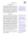
Figure 1 illustrates the basic steps for using the
OASIS Module Builder to create a PBO Lab
Application Module.
3
There are two parts to creating a
new Application Module for PBO
Lab:
1. Defining and building the
graphic interface components for
the Application Module, and
2. Creating the computation
engine library for the optics code
to be used by the Application
Module.
This Manual describes how to
accomplish part 1 using the
OASIS Module Builder.
The OASIS Module Builder
supports different configurations,
called "libraries" in this Manual,
for the beam optics computation
engines. In many cases it may
be possible to use an existing
library or executable for the
computation engine library.
This manual uses "computation
engine," "physics code," "optics
program," and similar terms to
refer to the underlying particle
beam optics program of an
OASIS Module.
OASIS User Manual
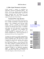
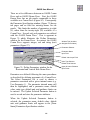
Develop
PBO Lab provides an intuitive,
interactive,
user
friendly,
graphic interface customized
to the needs of the accelerator
community.
A number of
Application Modules
have
been developed for PBO Lab.
The OASIS Module Builder
extends the utility of the PBO
Lab software by allowing
researchers to create their own
Application Modules for PBO
Lab.
OASIS Module
Builder
Save As
OModule.olab
OModule.omod
PBO Lab 3.0
main directory
OModule.dll
OModules
PBO-Lab.exe
Figure 1. The OASIS Module Builder is used to create
Application Modules for the Particle Beam Optics
Laboratory (PBO Lab).
Installing the OASIS Module Builder
The OASIS Module Builder is itself an Application
Module of the PBO Lab software framework -- a rather
special Application Module -- but an Application
Module nonetheless. The OASIS Module Builder is
shipped on CD-ROM with version PBO Lab 3.0 and
later, and is automatically installed when PBO Lab is
installed. The procedure for installing PBO Lab is
described in the Getting Started section of the PBO
Lab User Manual (Basic Package). The manual (PBOLab Basic.pdf) may be found inside the folder named
“Manual” on the PBO Lab CD-ROM. The PBO Lab
User Manual may also be downloaded (in PDF format)
from the AccelSoft website (www.ghga.com/accelsoft).
4
OASIS User Manual
To access the OASIS Module Builder you will need
to have a user license and CD-Key for the Module.
This information should be entered into the PBO Lab
Registration window after installation of the PBO
Lab software. If you are installing PBO Lab for the
first time, follow the instructions in the PBO Lab
User Manual (Basic Package). If you are adding the
OASIS Module Builder to an existing PBO Lab
installation, you will need to update your CD Key.
To do this, start PBO Lab in the (default) Single
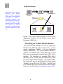
Model Mode. You should see a PBO Lab Document
Window like that illustrated in Figure 2. Under the
Tutorial menu of the Document Window select the
Register choice. A PBO Lab Registration window
will open. Enter your CD Key and/or other data as
necessary.
You will need to have PBO Lab
3.0 or later in order to utilize the
OASIS Module Builder. If you
already have PBO Lab 3 installed
on your computer, you will not
need to reinstall it. However, you
will need to have a user license
and CD-Key to use the OASIS
Module Builder. (OASIS will not
work properly with PBO Lab 2 or
earlier.)
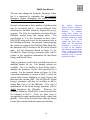
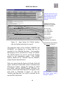
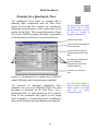
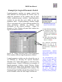
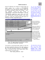
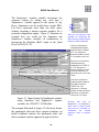
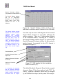
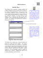
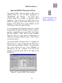
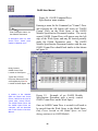
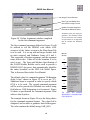
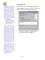
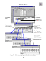
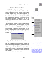
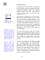
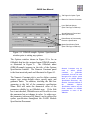
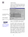
Menu Bar
Shortcut Buttons
Context Switch
Global Parameters
(on 3 Tab Panels)
Work Space
Model Space
Palette Bar
(PBO Lab Pieces)
Shortcut Button
Feedback (when mouse
is over Button)
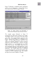
Figure 2. PBO-Lab Document Window with
selected features identified. The Tutorial
menu contains a Register selection.
5
Model Space Piece
Counter
OASIS User Manual
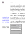
Initial Set Up
The PBO Lab installation CD
contains sample OModules
that were developed with the
OASIS Module Builder. These
are located in the folder named
Sample OModules. OModules
are contained in single files
and have names like:
"DIMAD-sample.omod".
The corresponding libraries of
the computation engines are
located in the folder named
Sample Computation Engines.
Some of these samples are
used for illustrations in this
Manual.
You may use the OASIS
Module Builder immediately
after installation of PBO Lab
and entering the license
number and CD Key. Modify
the PBO Lab Preferences in
order to access the OASIS
Module Builder.
After installation of the PBO Lab software has been
accomplished, the OASIS software is ready to run.
You may wish to install certain optional items from the
installation CD. A PDF version of this user manual is
contained in the Manuals folder on the CD. In
addition, some sample Application Modules built with
the OASIS Module Builder are also on the CD. The
sample OModules and corresponding computation
engines are contained in the folders Sample OModules
and Sample Computation Engines, respectively. Drag
these folders from the CD to the same directory
(folder) on your hard drive where PBO Lab is installed.
To set up and initialize the OASIS Module Builder
double-click (launch or start) the PBO-Lab.exe icon
located in the PBO Lab installation folder on your
computer. If PBO Lab has been launched from a fresh
installation, the software will open a Document
Window such as that illustrated in Figure 2. This is
referred to as the PBO-Lab Single Model mode. The
mode will need to be changed to the OASIS Module
Builder mode. To do this, mouse on the Tools menu in
the Document Window (Figure 2) and select the PBO
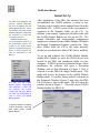
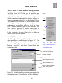
Lab Preferences item in the menu. This will open the
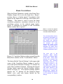
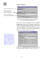
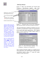
window shown in Figure 3. Select the choice OASIS
Module Builder for PBO Lab.
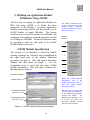
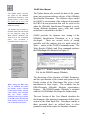
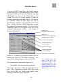
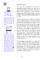
To initialize OASIS for creating
a PBO Lab Module, select the
radio button option: OASIS
Module Builder.
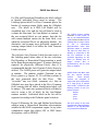
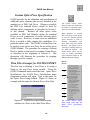
Figure 3. PBO-Lab Preferences window.
6
OASIS User Manual
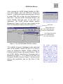
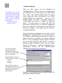
After selecting the OASIS Module Builder for PBOLab radio button, close the PBO-Lab Preferences
window. A dialog will appear indicating you will need
to restart PBO Lab in order for some Preferences to
take effect. Close the OASIS Document Window, and
restart (double click the icon of) the PBO Lab
application. The OASIS Module Builder window
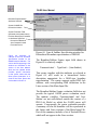
illustrated in Figure 4 will now open (instead of the
PBO Lab Document Window shown in Figure 2).
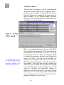
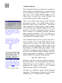
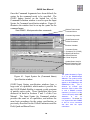
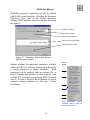
Close and Restart PBO Lab
after changing the Preferences
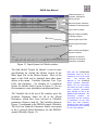
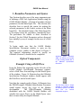
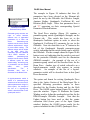
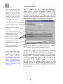
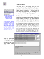
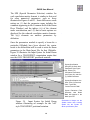
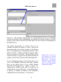
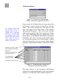
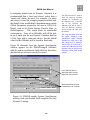
Menu Bar
Shortcut Buttons for:
PBO Lab Models
OASIS Modules
List of Open Documents:
OASIS Modules
PBO Lab Models
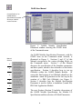
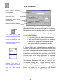
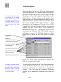
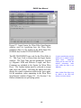
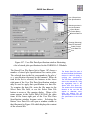
Figure 4. The OASIS Module Builder window.
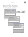
The Untitled1 document, highlighted in the right hand
pane of the window shown in Figure 4, is used to
create an Application Module. Double clicking the
Untitled1 item will open a Document Window. This is
an OASIS Module Specification Document and is
illustrated in Figure 5. It is similar to the PBO Lab
Document Window shown in Figure 3, but has special
features and capabilities that are the focus of this
Manual.
7
The
Module
Specification
Document is used to define
nearly all aspects of the
graphic interface for an
Application Module. When a
Module Specification Document
is completed, it will be saved
as an OASIS Module file, or
simply OModule file (file
extension .omod). A completed
OModule file contains all of the
information needed by PBO
Lab for an Application Module.
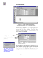
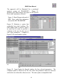
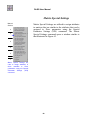
OASIS User Manual
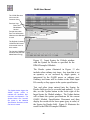
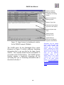
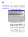
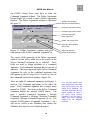
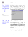
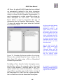
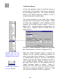
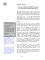
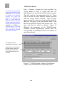
Context Switch of an
OASIS Module
Specification Document
Will Show "OASIS"
as the First Item
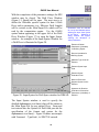
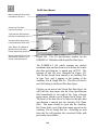
Figure 5. OASIS Module Specification
Document window showing the OASIS items
of the Commands menu.
Manual
Section
2
4
4
5
6
6
7
An OASIS Module Specification Document, with the
OASIS item on the Commands menu selected, is
illustrated in Figure 5. Sections 2 and 4-7 of this
Manual correspond to the various dividing blocks on
the Commands menu. Section 3 of this Manual
discusses the specification of the beamline parameters
and their syntax, which is also referred to as the lattice
specification. Section 8 describes how to test an
OModule within the OASIS Module Builder. Of
course the final testing of an OModule should use the
standalone .omod file generated as the last step in the
creation of a PBO Lab OModule (see Figure 1).
Section 9 describes how the Module Specification
Document is used to define a standalone (.omod file)
PBO Lab Application Module.
The next Section (Section 2) includes discussions of
the OASIS Module Specification, the Module I/O
Specification and the selection of Global Parameters.
8
O A S IS ™
OASIS User Manual
2. Defining an Application Module
OASIS User
Manual:
Building
Application
Modules
for PBO Lab™
9
OASIS User Manual
This page is intentionally blank.
10
OASIS User Manual
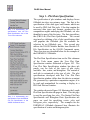
2. Defining an Application Module
(OModule) Using OASIS
The first step in creating an Application Module for
PBO Lab using OASIS is to define the basic
parameters of the Module. A generic Application
Module created using OASIS will be referred to as an
OASIS Module, or simply OModule. This Section
describes how to start the creation of an OModule, and
summarizes the minimum required parameters needed
for defining an OModule. Required parameters must
be specified in order for other parts of the OASIS
Module Builder to be active.
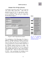
OASIS Module Specification
The creation of an OModule is started by double
clicking (opening) the Untitled1 object highlighted in
the right hand pane of the window illustrated
previously in Figure 4. This will open a Document
Window like that shown in Figure 5. Use the
Commands menu to select the first item: OASIS
Module Information. This will open a window like
that illustrated in Figure 6.
The OASIS Commands menu
is used to access many of the
Module
Builder
windows.
Section 2 discusses the first 3
items of the menu.
Manual
Section
2
4
4
5
6
6
7
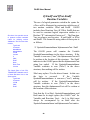
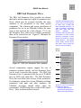
Required Information:
Select the OASIS Module
Specification item of the
OASIS Commands menu to
open the OASIS Module
Information window.
1. Module Name
The data used to illustrate the
Module Information Window is
for the DIMAD-sample Module
created with OASIS.
The
DIMAD-sample Module is one
of several new PBO Lab
Application Modules created
with the OASIS software.
2. Computation Engine
Type (.dll or .exe)
3. Computation Engine
Info (.dll or .exe)
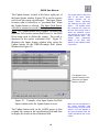
Figure 6. OASIS Module Information window.
11
OASIS User Manual
The OASIS Module Name will
appear in the Context Switch
of each PBO Lab Document
Window (Figure 2) when the
OModule is loaded. This name
will NOT appear in the context
of the OModule Specification
Document (Figure 5).
Once entered, the OASIS
Module Name will appear in
other places in the OModule
Specification Document. Below
is an example of how the
Commands menu appears for
the DIMAD-sample OModule
as specified in Figure 6.
Other items in the OModule
Specification Document will
also change as the OModule is
further defined. For example,
the Run entry on the
Commands menu for the
DIMAD-sample OModule has
the specified Main Input File
name (see the Module File I/O
Specification discussion on the
next page).
Several pieces of required data need to be entered into
the OASIS Module Information window. The required
data include the OASIS Module Name, the
Computational Engine radio selection, and the name of
the computational engine. There are two options for
the Computational Engine, as determined by the radio
button selection.
• If the Dynamic Link Library (DLL) radio button is
selected, then both the name of the Computational
Engine DLL and the Name of Entry Point into that
DLL need to be specified.
• If the Executable radio button is selected, then only
the Name of Executable for the computational engine
needs to be specified.
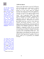
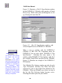
The other text fields of the OASIS Module Information
window are optional, but strongly recommended. The
data in the Version, Author, Organization, and
Comments fields are used to provide users of the
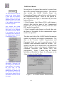
OModule with information about the Module. For
example, the data will be displayed in a tab panel of an
"About" window when a user requests information on
OModules accessible with his/her PBO Lab
configuration. Figure 7 shows how the Module
Information illustrated in Figure 6 will appear in the
About window for this Module.
Figure 7. An OASIS Module About window.
12
OASIS User Manual
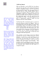
Module File I/O Specification
An OModule computation engine will access input and
write output using various files. These files are
identified using the File I/O Specification window.
Use the Commands menu to select the second item:
File I/O Specification. This will open a window like
that illustrated in Figure 8.
Manual
Section
2
4
4
5
6
6
7
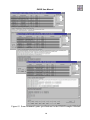
Figure 8. File I/O Specification window.
The specification of the Main Input File Name is
required. When the completed OModule is installed in
PBO Lab, the PBO Lab software will open and write
data to the Main Input File for use by the OModule. It
is also good practice to specify the Main Output File if
the OModule routinely generates text output. The
main input file and main output file are text files. The
other optional specifications are used for additional
files, including other input text files, output text files,
and graphics files. These are referred to as Auxiliary
I/O files. The specifications for handling various
Auxiliary I/O files are described in later sections.
13
The File I/O Specification
window is
accessed
by
selecting the second item on
the OASIS Commands.
OASIS User Manual
OASIS divides the Main Input
File into several primary
sections.
These primary
sections are designed to
support the input requirements
for a large group of particle
optics codes. OASIS uses the
following names for the four
primary sections:
Header
Lattice
Lines
Footer
Note that not all of the primary
sections of the Main Input File
need to be used for a given
OModule. Examples of Main
Input Files for various optics
codes are illustrated in Section
8 of this manual.
When writing the Main Input
File, an OModule first writes
the Header section, followed
by the Lattice section, the
Lines section, and concluded
with the Footer section.
Additional lines may be written
to the Main Input File between
these primary sections by the
use of OASIS Comm Pieces.
Comm Pieces are discussed in
Section 4.
When an OModule is used in PBO Lab, the software
will write the input data, in the format needed by the
Module’s computation engine, to the file specified by
the Main Input File Name. How the required format is
specified with the OASIS Module Builder forms a
major part of remainder of this User Manual. After the
computation engine has completed execution, the
primary text outputs from the calculation are written by
the computation engine to the file specified by the
Main Output File Name. This Main Output File will
then be automatically opened by PBO Lab and
displayed to the user of the OModule.
The Main Input File is divided into parts or sections for
discussion purposes in this User Manual. There are
four primary parts of the Main Input File referred to the
as the Header, Lattice, Lines and Footer sections. The
OASIS Module Builder writes data to the Main Input
File in a prescribed order that follows these parts. The
data content of the various parts of the Main Input File
are flexible, but the OModule developer should be
aware of the parts, and the order in which their data
will appear in the Main Input File.
The remainder of this Section of the User Manual
describes the selection of Global Parameters for the
OModule, as well as the way the data format for the
Header part of the Main Input File is defined. The data
format is defined by prescribing a syntax for text and
numbers that will appear in the Header.
The
procedures used for specifying the syntax are the same
as those to be used for defining the format of the data
for individual optics elements and other inputs to a
computation engine.
14
OASIS User Manual
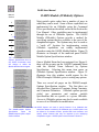
Global Parameter Selection
The OASIS Module Information and File I/O
Specifications are required for all OModules created
using the OASIS software. The next step in creating
an OModule is to begin the specification of the Main
Input File. Many optics computation engines will
utilize some of the PBO Lab Global Parameters. These
Global Parameters (Figure 2) can be used throughout
the Main Input File, and are also available to other
parts of the OModule. The particular use of Global
Parameters will be unique to each OModule created,
and their use is perhaps best explained by way of
illustration via specific OModule examples. The first
step in making Global Parameters available to the
OModule is to select them as OModule parameters.
This is described next. Then the procedures used to
place some of these parameters in the Header section
of a Main Input File will be described.
Use the OASIS Commands menu to select the item:
Global Parameters (Header). This will open the
Globals parameter selection window illustrated in
Figure 9.
Manual
Section
2
4
4
5
6
6
7
The Globals window is opened
by selecting the third item on
the OASIS Commands.
OASIS Syntax Button
Special Parameter Settings
(SPS) or "S" Buttons
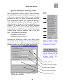
Figure 9. The Globals parameter selection window.
The Globals parameter selection window contains all
of the PBO Lab Global Parameters (Figure 2).
15
OASIS User Manual
All existing PBO Lab Global
Parameters are available for
use as Global Parameters in
the creation of an OASIS
Module. Global Parameters
may be utilized throughout the
OASIS Module Builder.
Click on a Special Parameter Setting (“S”) button to
open a new window that is used to assign attributes to
that parameter. The parameter can then be used by
other parts of OASIS and by the OModule itself.
Figure 10 illustrates the Special Parameter Setting
(SPS) window for the Global Parameter: Beam
Energy.
Symbolic Parameter
Name is Used to
Identify All Parameters
Selected Utilized in an
OModule
Units
Choices
Check Box to Select
Parameter of Use in
the OModule
Optional
Key Word
Different Options for
Utilizing the Parameter
Figure 10. Special Parameter Settings (SPS)
window for the Beam Energy Global Parameter.
An OModule developer can
also
define
and
utilize
additional custom parameters
throughout the OASIS Module
Builder. These form part of the
OModule Options and are
described in Section 4 of this
User Manual.
There are a number of useful and important features of
the Special Parameter Settings window that should be
noted.
First, a parameter is only selected for use elsewhere in
OASIS, or in the OModule being created, when the
box “Use this [Parameter Name] Parameter in these
Units” has been checked. Checking the box will create
a (default) Symbolic Parameter Name that appears in
the upper pane of the window. The default name
(GLOBALS1 in the example shown in Figure 10)
consists of two parts: a word identifier and a number.
The default word identifier is useful for locating that
Symbolic Parameter Name later during the OModule
definition.
The attached number is generated
sequentially during the OModule definition; this
assures that the default Symbolic Parameter Name will
always be unique.
16
OASIS User Manual
The user may change the Symbolic Parameter Name,
but it is important to remember that all Symbolic
Parameter Names throughout the entire OModule
Specification Document must be unique.
Second, each parameter has a number of attributes that
may be associated with it. Several different Units
selections are available, which are displayed by a popup menu. The Units for a parameter are selected by the
OModule creator using that pop-up menu. The
specification to “Use this Parameter in these Units”
tells OASIS what units to use for the parameter later in
the OModule definition. For example, when preparing
the syntax for writing to the OModule Main Input File,
the parameter will be written to the file in the selected
units. For the illustration shown in Figure 10, the
GLOBALS1 (Beam Energy) parameter value will be
written as the equivalent momentum for that Beam
Energy and Particle Mass.
Third, a parameter (in the Units specified) may also be
modified further for use. Two primary options are
available. One is to Modify by Scale Factor, that is,
multiply the parameter (in the Units specified) by a
constant. For the example shown in Figure 10, if the
equivalent momentum is desired in MeV/c, select the
second radio button (Multiply by Scale Factor) and
then enter the constant 1000. The GLOBALS1 (Beam
Energy) parameter will then be available in MeV/c
(rather than GeV/c) to the OModule. This type of
modification of the Beam Energy parameter will be
global throughout the OModule.
Whenever the
Symbolic Parameter GLOBALS1 is used it would then
be evaluated in MeV/c. There are other ways to
accomplish this same modification locally, rather than
globally. This will be described later when the format
for the data is defined with the syntax specification.
17
The
Special
Parameter
Settings provide a variety of
options for each parameter’s
attributes.
For example,
several Units options are
available. In the Beam Energy
parameter specification shown
in Figure 10, the Units
selection has been used to
specify that the equivalent
momentum, p, in GeV/c is to
be used for this OModule,
rather than the (default) kinetic
energy. Scaling by constants,
as well as modification of the
parameter using a formula,
provide more options.
OASIS User Manual
The set of numerical operands
available for use in formulas is
the same as those shown in
Figure 14. A Formula may be
used to redefine a Global
Parameter.
The redefined
Global Parameter will then be
available for use in the OASIS
Module, utilizing the same
name.
The alternate method for
implementing formula based
calculations uses the {Math}
features available for the Input
Syntax specification where the
Global Parameters are used.
In most cases, this alternative
method is the preferred
method
for
implementing
formulas. See Section 3 for a
discussion and examples.
Parameter
keywords,
or
parameter type codes, are
used by certain computation
engines.
For example, the
keywords might be used for
parameter fitting.
Another option available for modifying the value of a
parameter is to Modify with Formula. When the
Modify with Formula button is selected a formula can
be entered. Other Global Parameters may be used in
the formula, and a number of operands (+, -, *, /, sin(),
cos(), etc.) are available. Consider the case where the
beam total energy (kinetic energy + rest mass) is
desired. For this case, the Beam Energy could be
specified in Units MeV (GLOBALS1), and the Particle
Mass (another Global Parameter, see Figure 9)
specified in Units MeV (e.g. GLOBALS2). The
formula to be entered would then be GLOBALS1 +
GLOBALS2.
Whenever the Beam Energy
(GLOBALS1) is specified elsewhere in constructing
the OModule, it will be interpreted as the total energy,
and the numerical sum GLOBALS1 + GLOBALS2
will be provided. This type of modification of the
Beam Energy parameter will also be global throughout
the OModule. Whenever GLOBALS1 is used it would
then be interpreted as the total energy in MeV. This
result can also be achieved locally, rather than globally,
with a corresponding syntax specification.
Finally, a keyword (or type code) may be assigned to
each parameter. The keyword (or type code) is a
representation for that parameter that can be
recognized by the computation engine for the OModule
being created. For the example illustrated in Figure 10,
the GLOBALS1 (Beam Energy) parameter value in
equivalent momentum p(GeV/c) has been assigned the
keyword “P0” which is typical of TRANSPORT-like
computation engines.
18
OASIS User Manual
Not all codes use keywords or type codes. Even for
computation engines that do use keywords or type
codes for some parameters, not every available PBO
Lab parameter may have such a keyword or type code
for that computation engine. In other cases an optics
code may have been modified and improved at one
laboratory, so that new keywords (or type codes) not in
the original optics code are now used. OASIS makes
keyword (or type code) support available for all
parameters. This facilitates the OASIS Module creator
in maintaining and updating OModules as the
underlying optics code evolves.
Close the SPS window (Figure 10) when the input is
completed for the Beam Energy. The "S" button will
turn red, indicating that the Beam Energy parameter
has been given a Symbolic Parameter Name and has
SPS attributes assigned for use in the OModule. A
green dot will also then appear to right of the Beam
Energy parameter field of the Globals parameter
selection window. The green dot will also appear in
the Global Parameters pane of a PBO Lab Document
Window (Figure 2) when the context switch is set to
OModule name (e.g. DIMAD-sample), signifying that
the Beam Energy parameter is utilized by the OModule
for writing the Main Input File.
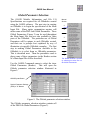
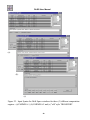
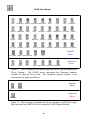
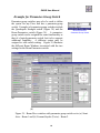
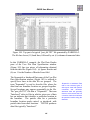
Other Global Parameters are selected for use by the
OModule, as needed, following the same procedures as
described for the Beam Energy. Figure 11 illustrates
how the Globals parameter selection window might
look after selection of a number of Global Parameters.
In the example illustrated, for the DIMAD-sample
OModule, all of the Global Parameters except for the
Beam Current and Minimum Step Size have red "S"
buttons and green dots, signifying that all but these 2
Global Parameters have been selected for use in the
OModule.
19
Support for different versions
of a computation engine is
relatively easy to maintain and
control with OASIS. OASIS
provides for multiple OModules
that can be loaded at the same
time, or loaded individually.
Different OModules can be
used to support different
versions of a computation
engine.
OASIS User Manual
Green Dots
Tell User
That These
Parameters
Are Utilized
Red S Buttons
Show That
Symbolic Parameter
Names Are Assigned
Figure 11. The Globals parameter selection window
for the example OModule: DIMAD-sample.
It is worth noting that the
numerical values of the Global
Parameters in the OModule
Specification Document will
not be used, except for certain
testing purposes as discussed
later in this Section. When the
completed OModule is used
for a beamline calculation, the
Global Parameters for the
PBO Lab Model used in the
beamline
calculation
are
utilized. The OASIS parser is
responsible for making these
substitutions at runtime. The
format for the use of the
substituted
parameters
is
defined by a syntax that the
OModule developer specifies.
A warning dialog will appear if
the OASIS button is used
before any parameters are
selected.
When the Global Parameters to be used by the
OModule have been selected they can be utilized
throughout the OModule. Examples of their use will
be illustrated in various Sections of this User Manual.
Header Syntax for the Main Input File:
Example of the DIMAD-sample OModule
Frequently the first use of the Global Parameters will
be in specifying the format for the Header section of
the Main Input File. This is described here. The
OASIS Module Builder provides for a variety of
capability in specifying the syntax for all parts of the
Main Input File. Only a few are discussed in this
Section, others are described in other Sections of the
User Manual. The reader may want to look at a
simpler example by skipping ahead to Section 3 and
reading the portion entitled "Example Using a Drift
Piece."
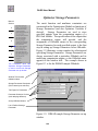
Select the OASIS syntax button on the Globals
parameter selection window (Figure 9) to open the
Input Syntax for Globals window. An example of this
window is shown in Figure 12 before any syntax has
been entered.
20
OASIS User Manual
Global Parameters, or
Variables, Available for
Defining Syntax
Runtime Dynamic Variables
Available for Defining Syntax
Type Code for Header
Defined Constant Available
for Defining Syntax
Header Syntax Input Field
Header Syntax Evaluation
Field
Button to Enter and Register
Syntax for Header
Operators for Runtime
Evaluation of Numerical
Parameters (Variables)
Figure 12. Input Syntax for Globals window.
The field labeled "Syntax for Header" is used to enter
specifications for writing the Header section of the
Main Input File in the desired format. Most of the
input to this field can be obtained from other items
shown in the menu: Variables, Run-time Vars, Type
Code, and Operators. An example of a completed
Syntax for Header field is given in Figure 13, but we
first summarize some information on important items.
The Variables list at the top of the window gives the
Symbolic Parameter Name for all of the Global
Parameters which have been selected as OModule
parameters (Figures 9 and 10). The Variables shown in
Figure 12 correspond to the DIMAD-sample OModule.
The first four Symbolic Parameter Names correspond
to the 4 selected Global Parameters for the DIMADsample OModule (Figure 11).
21
Note that the GLOBALSXX
parameters need not all be
selected for use at the same
time.
The numbers XX
attached to the GLOBALS
default Symbolic Parameter
Names are not consecutive,
and reflect the order in which
these particular parameters
were selected for use in the
DIMAD-sample OModule. The
intervening
numbers
are
associated with the selection
of parameters for the Drift,
Quad, and other elements,
assigned in the order in which
the parameters were selected
for use in the OModule
OASIS User Manual
The Variables list also contains an additional Symbolic
Parameter Name: CONST94. This is an example of a
Numeric Constant option for an OModule. The
specification of OModule options is discussed in detail
in Section 4. This example is included here to
illustrate how additional user-editable data can be
incorporated into the Header by use of OModule
options.
Run-time Vars provide access
to dynamic runtime variables
useful for defining various
OModules. The Run-time Vars
include:
TypeCode
Comment
ModelName
ModuleName
!COM
Include
If
IfNot
Endif
Date
Date-Time
Version
The DIMAD-sample OModule
uses 4 of these Run-time Vars
in the Header syntax:
!COM
Date-Time
ModelName
Version
Both Variables and Run-time
Vars always need to be
enclosed in single quotes for
the OASIS syntax parser to
correctly evaluate them at
runtime.
The Run-time Vars are variables evaluated at run time
when the OModule is used to operate on a PBO Lab
model file. The runtime variables provide dynamic
data that is different from the user-editable PBO Lab
Parameters such as the Global Parameters. Not all
runtime variables are appropriate for the Header
section and only four are discussed here: !COM,
DateTime, ModelName, Version. Other Run-time
Vars are discussed is Section 3.
The Type Code field is used to store an alphanumeric
string for the Header section that will be evaluated at
runtime wherever the Run-time Var 'TypeCode'
appears in the syntax. The Type Code field is most
typically used in connection with specifying the Main
Input File syntax for individual optics elements (PBO
Lab Pieces) and examples are discussed in Section 3.
The Operators provide a selection of mathematical
functions that can operate on the Variables at runtime.
The Operators may be used in the Header section, but
the discussion of their use is deferred until Section 3.
Variables and Run-time Vars can be entered into the
Header Syntax by clicking on the desired item in the
appropriate list. The selected item will appear in the
Syntax in single quotes. For example, clicking on the
!COM item in the Run-time Vars list will result in an
entry '!COM' appearing in the Syntax specification
field at the location where the cursor was last placed.
22
OASIS User Manual
Variables and Run-time Vars are always identified in
Syntax fields by single quotes. Variables and Runtime Vars may also be typed directly into the Syntax
specification field, but the single quotes must be
included for the OASIS syntax parser to properly
evaluate the entries at runtime.
The !COM item in the Run-time Vars list is a comment
delimiter for adding text comments to the Main Input
File. The comment delimiter tells the computation
engine to "ignore" the associated text. Computation
engines generally have only a few allowed comment
delimiters and many have only one.
Comment
delimiter selections for an OModule are made using the
OModule Options Specification and are discussed in
Section 4. The comment delimiter for the DIMADsample OModule is the exclamation point (!). The
entry '!COM' will be evaluated at runtime as !
wherever it appears in a Syntax specification field.
Likewise, wherever the Variables entry 'GLOBALS1'
appears in a syntax specification it will be evaluated at
runtime, when the Main Input File is written, to the
Beam Energy Global Parameter of the PBO Lab
Model. Similar comments apply for any Variables
entries
'GLOBALS31',
'GLOBALS57'
and
'GLOBALS79' - these evaluate to the PBO Lab Model
values for the Particle Mass, Frequency and Particle
Charge, respectively.
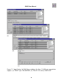
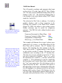
Figure 13 illustrates the Header syntax specification for
the DIMAD-sample OModule. The five '!COM'
entries are used to start the Main Input File with 5
comment lines. These comment lines include ordinary
text (simply typed in) as well as three Run-time Vars:
'Date-Time', 'ModelName' and 'Version'.
23
Both the !COM Run-time Var
and the CONST94 Variable
are defined by the DIMADsample Options Specification.
The
OModule
Options
Specifications are discussed in
Section 4.
OASIS User Manual
The '!COM' Run-time
Var is used for
Comment Lines
Run-time Vars:
'Date-Time'
'ModelName'
'Version'
Provide Users with
Run Time Information
Whenever the OModule
is used.
The Defined Constant
'CONST94' Will Insert
A Numerical Value at
this Location
The Variable 'GLOBAL1'
Will Insert the PBO Lab
Model Beam Energy
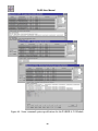
Figure 13. Input Syntax for Globals window
with the Syntax for Header as specified for the
DIMAD-sample OModule.
The Header syntax illustrated in Figure 13 also
includes other ordinary text items. Any item that is not
an operator, or not enclosed by single quotes, is
interpreted by the OASIS parser as ordinary text.
Ordinary text items will be written to the Main Input
File exactly as they appear in the syntax specification.
The Update button triggers the
OASIS syntax parser to
evaluate the Variables, Runtime Vars, and Operators. The
Update button also "records"
the syntax in the OModule
Specification Document, which
can then be saved.
Text and other items entered into the Syntax for
Header field need to be recorded and updated. To do
this, use the Update button in the lower right of the
Input Syntax for Globals window. The Update button
will evaluate the syntax specifications for the current
OASIS Module Specification Document and then
display the results in the lower pane (gray in color) of
the Syntax for Header field. Figure 14 illustrates the
result for the DIMAD-sample OModule.
24
OASIS User Manual
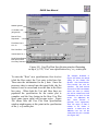
Variables and Run-time Vars
are evaluated for the OASIS
Module Builder Document
when the Update button is
selected.
'!COM' Run-time Var is
Evaluated to ! (Comment
Delimiter for DIMAD)
Run-time Vars:
'Date-Time'
'ModelName'
'Version'
are Evaluated.
Numerical Values
Substituted for
'CONST94' & 'GLOBALS1'
Figure 14. Input Syntax for Globals window
after the Update button has been used.
Update Button Both Updates
and Records the Syntax
The numerical values of the Variables 'CONST94' and
'GLOBALS1' are displayed in a format that can be
specified by the OModule developer. Real numbers
and integers can be specified in a variety of formats.
The OASIS Options are used to specify the formats
needed by the computation engine. (The OASIS
Options should not be confused with the DIMADsample Options Specifications.)
Other text entered into the Syntax for Header field will
appear unaltered in the Header syntax evaluation field
following an Update. During the running of a PBO
Lab Model with the DIMAD-sample OModule, the
Header section of the Main Input File will appear in the
same form as illustrated in Figure 14, only the
Variables and Run-time Vars will be evaluated for the
specific PBO Lab Model.
25
Numerical format is specified
with OASIS Options and is
described in Section 7.
OASIS User Manual
The Update button "records"
the syntax for the OModule
Specification Document. If the
Update button is NOT used,
the syntax will be lost if the
Input for Globals Syntax
window is closed.
The Header can be written to
the Main Input File and viewed
for test purposes using the
Write Header (Globals) and
View item on the commands
menu. This command is
described further in Section 6.
The Update button also records the data of the syntax
items into persistent software objects of the OModule
Specification Document. The software object model
for OASIS is an extension of the software object model
for PBO Lab and persistent data will be saved to file
when the OModule Specification Document is saved.
Saving different document types (.olab and .omod
extensions) is described in Section 7.
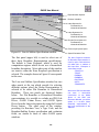
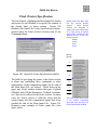
OASIS provides for dynamic user testing of the
OModule Specification Document as it is being
developed.
There are several levels of testing
available, and the simplest tests are made using the
Write… entries of the OASIS Commands menu. The
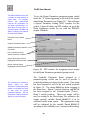
Write Header (Globals) and View command produces
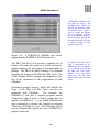
the DiMadInput file illustrated in Figure 15.
Figure 15. Header Section of the Main Input
File for the DIMAD-sample OModule.
When writing the Main Input
File, an OModule first writes
the Header section, followed
by the Lattice section, optional
Lines section, and concludes
with the Footer section.
Additional lines may be written
to the Main Input File between
these primary sections by the
use of OASIS Comm Pieces.
The discussion of the selection of Global Parameters,
and the specification of the format and syntax for the
Header section of the Main Input File, gives a brief
introduction to these topics. The examples for the
DIMAD-sample OModule illustrate representative
features. The DIMAD-sample OModule is included
with the OASIS Module Developer for further study.
The next Section of this User Manual describes the
development of the principal components of the Lattice
section of the Main Input File. Procedures similar to
those presented above are utilized there to select
parameters and define syntax for beamline elements.
26
O A S IS ™
OASIS User Manual
3. Beamline Parameters & Syntax
OASIS User
Manual:
Building
Application
Modules
for PBO Lab™
27
OASIS User Manual
This page is intentionally blank.
28
OASIS User Manual
3. Beamline Parameters and Syntax
This Section describes one of the more important parts
of defining a PBO Lab Application Module using the
OASIS Module Builder: selection of beamline element
parameters for the Main Input File. This Section also
describes how to specify the syntax for writing the
selected parameters to the Lattice section of the Main
Input File. The detailed format of the Main Input File
is developed using the procedures summarized here.
The procedures are similar to those described in
Section 2 for the Global Parameters and are discussed
here initially by way of example for the case of a Drift
Piece.
To begin, make sure that the OASIS Module
Specification Document window is open on the
computer screen, similar to that shown in Figure 5.
The required information needed to specify an
OModule (Section 2) should also be completed.
Optical Components
Example Using a Drift Piece
Individual optics elements
(PBO Lab Pieces) are located
on the scrolling Palette Bar of
the OModule Specification
Document.
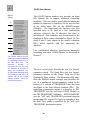
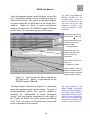
From the Palette Bar appearing on the left side of the
OASIS Module Specification Document window,
select a Drift Piece icon and drag it to the Model Space
of the window. Figure 16 illustrates how the OModule
Specification Document window should appear with
the Drift Piece on the Model Space.
Note that the example used in Figure 16 illustrates how
the DIMAD-sample OModule Specification Document
would appear during this stage of the Module
development.
The DIMAD-sample OModule
distributed with the OASIS Module Builder will
actually have more Pieces on the Model Space since
that is a more fully developed OModule.
29
The Drift Piece offers a simple
example to illustrate creating
the element syntax of the Main
Input
File
for
several
computation engines.
OASIS User Manual
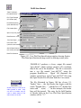
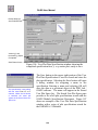
Figure 16. OASIS Module Specification
Document with Drift Piece on the Model Space.
Double click the Drift Piece icon on the Model Space
to open the Drift Piece window. The Drift Piece
window is shown in Figure 17. Several features of the
Piece window are indicated.
OASIS Syntax Button
Special Parameter Selection
(“S”) Buttons
Figure 17. Drift Piece window with selected
features identified.
The OASIS Syntax Button
cannot be used to define
syntax before any parameters
have been selected.
The procedures for the selection of parameters for use
by an OModule, together with the syntax specification
for writing data to the Main Input File, are very similar
to the procedures described for the Global Parameters.
30
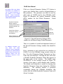
OASIS User Manual
Selecting the “S” button will open the Special
Parameter Settings (SPS) window for the parameter.
The SPS window for the Effective Drift Length is
illustrated in Figure 18. Figure 18 also identifies
several features of the SPS window for the OASIS
Module Builder.
Parameter Name
Symbolic
Field
Parameter
Name
OASIS Tab Panel
Tab Panels for Other Installed
PBO Lab Modules (not used
by OASIS Module Builder).
OModule Parameter Selection
Check Box
Figure 18. Special Parameter Settings
(SPS) window for Effective Drift Length.
Clicking the OModule parameter selection check box,
appearing in the upper left of the OASIS tab panel, will
select the Effective Drift Length as a parameter that
will be used by the OModule under construction.
When the box is checked, a default name will appear in
the Symbolic Parameter Name field, and other parts of
the window will become active. Figure 19 illustrates a
typical appearance for the SPS window when the
Effective Drift Length parameter check box is selected.
The example used for Figure 19 is from the OModule
DIMAD-sample. Selecting the check box activates:
the units selection popup menu, the Parameter
Keyword field, and sets the radio button to the default:
Use this Parameter in these Units. Other radio button
choices offer different options for the numerical value
of the parameter to be used in the OModule. These
other options are the same as those described in
Section 2 for the Global Parameters.
31
Different options in the SPS
window are used to specify
how the selected parameter
will be made available to the
OModule.
Units, keywords,
and other attributes can be
assigned.
OASIS User Manual
Default Symbolic Parameter
Name Assigned
OModule Units Selection Popup Becomes Active
Radio Buttons Become Active
and Default Set
OModule Parameter Keyword
Field Becomes Active
Figure 19. Special Parameter Settings (SPS) window
when the OModule parameter selection box is checked.
Elements activated by checking this box are indicated.
A red O will appear on the
Piece icon for which a
parameter selection has been
made. This designates the
Piece as an OASIS Piece and
indicates that at least one
parameter has been selected
for use in an OModule.
To complete the selection of the Effective Drift Length
for use in the OModule:
• Select the OModule units for this parameter
• Enter any OModule keyword for the parameter
• Choose the appropriate radio button option
and enter additional information if needed.
In Figure 19 the units option for meters (m) has been
selected, the DIMAD key word L has been entered, and
the default setting for the parameter usage has been set.
Length Units Popup
PBO Lab supports the input of
parameters in a variety of
units, including "smart units"
such as βλ (βLambda) for
length. The OASIS Module
Builder supports the same
units.
It should be noted that the data appearing in the OASIS
Piece Window is not used directly by an OModule.
The particular values of the Effective Drift Length,
Pipe Aperture Radius, etc., in the OModule
Specification Document will not be used for any
calculations (other than OASIS Module Builder
internal testing). When the OModule is utilized by a
user for a particular PBO Lab Model that contains Drift
Pieces, the values for the parameters will obtained
from the Drift Pieces of that PBO Lab Model.
32
OASIS User Manual
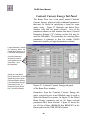
With the completion of the parameter settings, the SPS
window may be closed. The Drift Piece Window
(Figure 11) should still be open. The next step is to
define the OModule specific syntax for how a Drift
Piece and its parameters (e.g. Effective Drift Length)
will be written to the Main Input File which will be
read by the computation engine. Use the OASIS
syntax button appearing in the upper left of the Drift
Piece Window (Figure 17) to open the Input Syntax
window. An example of the Input Syntax Window for
a Drift Piece is illustrated in Figure 20.
Parameters must be selected
for use by the OModule before
defining the Input Card Syntax
for the Piece.
Otherwise a
dialog window will appear
advising the developer to
select parameters.
Element & Global
Parameters (Variables)
for Defining Syntax
Runtime Variables for
Defining Syntax
OModule Type Code for
Element
Element Syntax Input
Field
Element Syntax
Evaluation Field
Button to Enter and
Register Syntax for this
Element
Figure 20. Input Syntax for Drift Space window for DIMAD.
The Input Syntax window is used to specify the
detailed alphanumeric text line(s) that will be written to
the Main Input File for any optical Piece. Items and
text entered into the Syntax for Drift field provide the
specification of the format and syntax for the
alphanumeric text line(s). Figure 20 shows an example
with ‘Comment’ : ‘TypeCode’, L= ‘DRIFT10’ entered.
33
Operators for Runtime
Evaluation of Numerical
Parameters (Variables) of
Element
OASIS User Manual
There are several features of the Input Syntax window
that should be noted. First, the parameters available
for use in writing to the Main Input File are given in
the Variables list at the top of the window. This list
includes all parameters of the Piece selected for use
(see Figure 19) in the OModule, together with any
Global Parameters also selected for use (see Figure 12)
in the OModule. Second, a list of runtime variables
(Run-time Vars) available for use in defining the
syntax is shown in the upper right part of the window.
Third, a field is available for specifying any Type Code
that is used by the OModule for the Drift. Fourth, a
variety of numerical operators are available for use in
defining the syntax.
The Input Syntax window
offers a number of features for
use in defining how an optics
component is written to the
Main Input File for an OModule
computation engine. Only a
few of these capabilities are
needed to specify the text line
(Input Syntax) for the Drift
Piece of the DIMAD-sample
OModule.
The Input Syntax refers to the text line (or lines) that
will be written to the Main Input File for the OModule
computation engine. The example shown in Figure 20
corresponds to the Drift Piece syntax defined for use
by the DIMAD computation engine. The first item in
the Input Card Syntax is the Comment ('Comment')
runtime variable. The Comment is followed by a colon
(:) and a second runtime variable, the Type Code
('TypeCode'). The Type Code is followed by a comma
and parameter assignment string (, L=). The parameter
value is given by the DRIFT10 Variable ('DRIFT10').
The DIMAD Type Code for a drift is entered into the
Type Code field (DRFT). Note that all Variables and
Run-time Vars must be enclosed in single quotes. How
is this Input Syntax used? When PBO Lab has the
OModule installed, the Input Syntax is used for each
Drift Piece in any beamline model to write the
appropriate card to the Main Input File. The Variables
and Run-time Vars ('Comment', 'TypeCode', and
'DRIFT10') are evaluated for each drift, and the
appropriate text and numerical data are then written to
the Main Input File.
34
OASIS User Manual
The Update button, located in the lower right part of
the Input Syntax window (Figure 20) is used to register
and record the syntax specification. The Input Syntax
becomes what is referred to as “persistent data” when
the Update button is selected. The Input Card Syntax
will not be retained or saved if the Update button is not
used. The Update button also evaluates Variables and
Run-time Vars for the current Drift Piece (i.e. the Drift
Piece being used to define the syntax). The result is
displayed in the syntax evaluation field. Figure 21
illustrates the Input Syntax window after using the
Update button for the DIMAD-sample Drift syntax
illustrated in Figure 20.
The Update button in the lower
right of the Input Syntax
window operates like an
“accept” button, registering
and retaining the Input Card
Syntax. The Update button
also evaluates the syntax for
the Drift Piece being used to
define the OModule syntax,
and displays the results in the
syntax evaluation pane. This
permits
some
preliminary
testing of the Input Card
Syntax for the OModule under
construction
Text Appears in the
Syntax Evaluation Field
Whenever the Update
Button is Selected
Figure 21. Example of an Input Syntax for Drift
Space window after the Update button is used.
The Update button calls on the OASIS parser to first
evaluate the syntax in the specification field and then
to display the results in the evaluation field.
35
Make sure that text appears in
the syntax evaluation field
before closing an Input Syntax
window. If no text appears in
the syntax evaluation field, the
syntax specification will not be
saved!
OASIS User Manual
.
The Drift Piece Comments
field (see Figure 17) for the
DIMAD-sample
OModule
shown in Figure 21 has XSIFDRIFT entered (rather than the
Drift Piece default: DRIFT).
This comment refers to the
eXtended
Standard
Input
Format utilized by a number of
particle beam optics codes.
The Standard Input Format
(SIF)
and
Methodical
Accelerator Description (MAD)
formats can be considered
simpler versions of XSIF. The
DIMAD-sample OModule can
be used as a starting point in
developing OModules that use
the XSIF, SIF or MAD input file
descriptions.
Whenever the Update button is used, the OASIS parser
utilizes data for the syntax evaluation that is obtained
from the (OASIS) Piece itself. This provides an
internal test of the syntax which the OModule
developer can examine for accuracy and completeness.
The data in the OASIS Piece can be modified by the
developer in order to test different aspects of the
syntax. This is particularly useful if the syntax
contains mathematical expressions. Sometimes there
may be a specific set of Piece parameters that is
particularly useful for testing syntax that contains
mathematical formulas. That data may be entered in
the OASIS Piece and it will be saved when the
OModule Specification Document is saved. Data
entered into an OASIS Piece and saved with the
OModule Specification Document will not impact the
operation of the OModule in PBO Lab. When an
OModule is instantiated in PBO Lab by a user, the
OASIS parser will act upon the data present in the PBO
Lab model under investigation, regardless of what data
is present in the corresponding OASIS Piece. The
Update button is one of the few times that the specific
numerical data in an OASIS Piece is used. However, it
provides a quick and interactive capability to test each
Piece's syntax as it is specified by an OModule
developer.
The OASIS parser provides
some feedback in the event
that syntax and/or variables
are improperly defined. For
example, suppose the syntax
refers to a Variable named
BAD22, e.g. the single-quoted
string 'BAD22' appears in the
syntax, but BAD22 has not
been defined.
The OASIS
parser will display the following
for BAD22 in the evaluation
field:
Variable can not be found
36
OASIS User Manual
Drift Syntax for Different Computation
Engines
Figure 22 shows some Input Syntax for Drift Space
windows with syntax developed for three (3) different
computation engines. From top to bottom these
computation engines are:
(a) PARMILA-1, (b)
PARMILA-2 and (c) the "old" style TRANSPORT.
PARMILA-1 corresponds to the version of PARMILA
that was in common use prior to ~1998. PARMILA-2
corresponds to the version that has been in prominent
use since that time. One difference between these
PARMILA versions is how transport elements (e.g.
drifts) are described in their respective input files. The
old style TRANSPORT refers to versions of
TRANSPORT that still use the original positional
notation input file.
Figure 23 shows some Input Syntax for Drift Space
windows with syntax developed for three (3) additional
computation engines. From top to bottom these
computation engines are:
(a) "MAD" style
TRANSPORT, (b) TRACE 3-D and (c) MARLYIE.
The MAD style TRANSPORT version uses
descriptions of beamline elements that are similar to
those in the DIMAD-sample OModule.
The Input Syntax windows shown in Figures 22 and 23
are typical of the spectrum of input formats for
different computation engines.
Note that the
PARMILA-1 and TRACE 3-D use the Run-time Vars
‘Sequence’.
The ‘Sequence’ runtime variable is
discussed further in the quadrupole example section.
For the Comments field of the Drift Pieces (see Figure
21) used for Figures 22 and 23, the name of the
underlying computation engine has been entered. The
runtime variable ‘Comment’ as evaluated in the Syntax
Evaluation Field reflects this name.
37
Although the syntax for drift
elements does not use any
Global Parameters, it is worth
noting the different uses
shown in Figures 22 and 23:
The examples show various
Global Parameters for each
computation engine: Particle
Charge, Particle Mass, Beam
Energy, Beam Current, etc.
Different units have been
specified for some of the
Global Parameters.
For
example, the Beam Energy is
specified to be expressed in
terms of the beam momentum
(GeV/c) for the TRANSPORT
examples. Also note that the
Particle Mass is multiplied by a
factor for the PARMILA
examples in order to comply
with the conventions of those
codes.
OASIS User Manual
(a)
(b)
(c)
Figure 22. Input Syntax for Drift Space windows for three (3) different computation
engines: (a) PARMILA-1, (b) PARMILA-2 and (c) "old" style TRANSPORT.
38
OASIS User Manual
(a)
(b)
(c)
Figure 23. Input Syntax for Drift Space windows for three (3) different computation
engines: (a) "MAD" style TRANSPORT, (b) TRACE 3-D and (c) MARYLIE.
39
OASIS User Manual
Manual
Section
2
4
4
5
6
As mentioned, the comments for the Drift Pieces used
in Figures 22 and 23 have the name of the underlying
computation engine entered into the Comments field.
The OASIS parser evaluates the runtime variable
‘Comment’ and puts this name in the syntax evaluation
field when the Update button is selected. However, it
is worth noting here that the ‘Comment’ runtime
variable can also take on different values for
hierarchical lattice descriptions.
How this is
accomplished is discussed in Section 4. When certain
hierarchical lattice descriptions are specified, the
OASIS parser can substitute a dynamic labeling for
each ‘Comment’ runtime variable when the OModule is
used in calculations for a PBO Lab Model.
6
7
The Lines and Sublines
Specification can be used to
define the labeling scheme for
hierarchical beamline lattice
descriptions. The ‘Comment’
Run-time
Vars
can
be
evaluated to a unique dynamic
label in support of hierarchical
lattice descriptions.
40
OASIS User Manual
Example for a Quadrupole Piece
The Quadrupole Piece offers an example that is
modestly more complicated than the Drift Piece.
Figure 24 shows the Piece window for a quadrupole,
illustrating several features of the window that are not
present for the Drift. The example illustrated in Figure
24 is for the DIMAD-example, and shows 4 parameters
on the Element pane that have been selected for use.
The Quad Piece has multiple
tab panels, each of which
provides parameters that can
be used to describe a
magnetic quadrupole lens.
OASIS Syntax Button
Tabs for Panels with Additional
Piece Parameters
Parameter Group Switch for
Selecting Different Parameter
Sets
Four Parameters Selected for
Use in the OModule,
Designated by Green Dots ●
and Red S Buttons
Comment (or Label) Input
Field
Figure 24. Quadrupole Piece window for the DIMADsample OModule with selected features identified.
The selection of individual Quadrupole Piece
parameters for use in an OModule follows the same
procedure as described for the Drift Piece. For a
quadrupole there are more parameters to be selected.
Some of the parameters may appear on the Fringe
Field, Geometry or Location tab panels, in addition to
those on the Element tab panel illustrated in Figure 24.
41
The Quad Piece example is
used to illustrate creating the
element syntax of the Main
Input
File
for
several
computation engines.
OASIS User Manual
Quadrupole Strength
Parameter-Group Switch
Parameter-group switches are
used to select between
different sets of dependent
parameters for a PBO Lab
Piece.
Parameter-group
switches can be used to define
different alphanumeric strings
for each switch setting. The
different strings will be written
to the Main Input File,
depending upon the OModule
user’s switch selection. In
addition,
parameter-group
switches can be used to define
a different syntax for each
switch setting. An entire group
of parameters can be utilized
within
each
syntax
specification.
This
is
described
later
and
is
illustrated for the Beam Piece.
A logical-parameter switch is
similar to a parameter-group
switch and can also be used to
define alphanumeric strings for
Piece syntax. An example of
the use of a logical-group
switch is described later in this
quadrupole section.
The example in Figure 24 indicates that four (4)
parameters have been selected on the Element tab
panel for use by the OModule: the Effective Length,
Aperture Radius, Quadrupole Coefficient K1, and
Rotation (Roll) Angle. These four parameters have a
red “S” appearing on their corresponding Special
Parameter Selection buttons.
The Quad Piece window (Figure 24) contains a
parameter-group switch (Quadrupole Strength) on the
Element tab. This switch has been set to the
Quadrupole Coefficient option in order to select the
Quadrupole Coefficient K1 parameter for use in the
OModule. Note also that there is an "S" button to the
left of the Quadrupole Strength parameter-group
switch, indicating that the switch setting can be used by
the OModule. For the example shown in Figure 24 the
button is not red, indicating that the switch is not used
for the particular OModule used for the illustration
(DIMAD-example). An example of the use of a
parameter-group switch will be described later for the
Beam Piece. Another type of switch, referred to as a
logical-parameter switch, also appears in certain
windows. An example of the use of a logicalparameter switch will be described later in this Quad
Piece discussion.
The syntax and format for writing Quadrupole Piece
data to the Lattice Section of the Main Input File is
specified following procedures similar to those
described for the Header Section and for the Drift
Piece. The OASIS syntax button (Figure 24) is used to
open the window. Figure 25 illustrates the Syntax
Window used to define the quadrupole text line for the
DIMAD-sample OModule example. Note that the
Update button has been used so that the syntax
evaluation field (lower pane of the Input Syntax
window) displays the OASIS parser results for the
syntax evaluation for this (OASIS) Quadrupole Piece.
42
OASIS User Manual
Element, Global &
Defined Parameters
(Variables) for Defining
Syntax
Runtime Variables for
Defining Syntax
Element Type Code
Parameter-Group Switch
(Ignored for this Syntax)
Element Syntax Input
Field
Element Syntax
Evaluation Field
Update Button to
Evaluate and Register
Syntax for this Element
Figure 25. Input Syntax for Quadrupole window
for the DIMAD-sample OModule.
The OASIS parser for the Quadrupole Piece syntax
illustrated in Figure 25 utilizes additional formatting
information that is not specified in the Input Syntax
window. The scientific format for the real numbers is
governed by the OASIS Options. The OASIS Options
window contains a Numerical Formatting tab for
specifying this type of formatting information and is
described in Section 7.
43
Remember that the Update
button in the lower right of the
Input Syntax window also
operates like an “accept”
button. Selecting the button
will register and store the Input
Syntax, as well as display the
result (for the particular
parameter values of the
OASIS Piece) in the syntax
evaluation box in the lower
part of the Input Syntax
window. If no text appears in
the syntax evaluation box, the
syntax specification will not be
saved.
OASIS User Manual
Manual
Section
2
4
4
5
6
6
7
The OASIS Options provide
additional formatting capability
for specifying the text lines of
the Main Input File.
The
maximum
number
of
characters per line (e.g. 68),
the character to be used to
signify line continuation (e.g.
&), and similar formatting items
are provided on the Input File
Options tab of the OASIS
Options window. These are
discussed in Section 7.
The OASIS Options window also provides an Input
File Options tab to support additional formatting
capability. This was used to specify that the maximum
number of characters be limited to 68 for any one line
of the Main Input File for the DIMAD-sample
OModule. The ampersand (&) character was also
specified there to be used as a line continuation
character whenever the 68 character line limit is
encountered. This condition was encountered for the
Quadrupole Piece syntax illustrated in Figure 25. The
result is that 2 lines appear in the syntax evaluation
field, linked together with the ampersand (&)
character.
Line continuation character specification, numerical
formatting, and other OASIS Options are discussed in
Section 7.
The next several pages describe the use of a logicalparameter switch. The Quad Piece has two logicalparameter switches on the Fringe Field tab of the
Quadrupole Piece window. The discussion shifts away
from the DIMAD-sample example and describes the
use of a quadrupole logical-parameter switch in the
context of a version of TRANSPORT that has been
developed at the Paul Scherrer Institute (PSI). The
underlying computation engine is referred to as PSITRANSPORT and the associated OASIS Module as
the PSI-TRANSPORT OModule. PSI-TRANSPORT
uses the "old" style TRANSPORT positional notation
for the input file. Figure 22(c) gave an example of how
the Drift Piece syntax is specified for the "old" style
TRANSPORT positional notation.
44
OASIS User Manual
Example for Logical-Parameter Switch
Logical-parameter switches are popup controls that
offer different text descriptions for various ways in
which the parameters in the window may be used.
Unlike parameter-group switches, logical-parameter
switches do not alter the user's ability to edit any
parameter value. Logical-parameter switches simply
offer a convenient way to select different methods for
using parameters, utilizing an intuitive word
description of the choices available.
Figure 26
illustrates a Piece Window tab panel that contains two
logical-parameter switches.
Quadrupole Fringe Field
Logical--Parameter Switch
2 Logical Parameter Switches:
One ("Entrance Fringe Field")
Is Selected for Use in the
OModule, as Designated by
the Green Dot ● and Red S
Button
The Other ("Exit Fringe Field")
is Not Selected for Use (No
Green ● or Red S).
Four Numerical Parameters
Selected for Use in the
OModule, as Designated by
the Green Dots ● and Red S
Buttons
Figure 26. Fringe Field tab panel of the Quadrupole
Piece window with two logical-parameter switches.
Logical-parameter switches can be selected for use in
an OModule by choosing the Special Parameter
Selection ("S") button that appears to the left of the
parameter name. Figure 26 illustrates two examples of
logical-parameter switches, named Entrance Fringe
Field and Exit Fringe Field, appearing on the Fringe
Field tab panel of the Quadrupole Piece window. The
Entrance Fringe Field has already been selected for use
in the OModule, while the Exit Fringe Field has not.
45
Logical-parameter
switches
can be used to define different
alphanumeric strings for each
switch setting.
The PSI-TRANSPORT code
supports soft-edge quadrupole
nd
modeling through 2
order.
This involves the use of the
gradient integrals I1, I2 and I3.
For a hard-edge quadrupole
these integrals are all zero. A
PSI-TRANSPORT
OModule
has been developed that
illustrates how to support this
fringe field modeling capability.
OASIS User Manual
The PSI-TRANSPORT code
models soft-edge quadrupoles
through the use of the gradient
integrals I1, I2 and I3. For
hard-edge quadrupoles these
integrals are zero. A logicalparameter switch will be used
to distinguish these cases.
The “S” button to the left of each logical-parameter
switch opens a Special Parameter Settings (SPS)
window that is different from the SPS window used for
numerical Piece Parameters (see Figure 19). The SPS
window for the first logical-parameter switch (Entrance
Fringe Field) of Figure 26 is illustrated in Figure 27.
Logical-Parameter Name
Symbolic Parameter Name
OModule Parameter Selection
Check Box
Option (if unchecked) to Define
Different Syntax for a GroupParameter Switch Setting
List of Logical-Parameter
Switch Selections Available
Syntax String Input Field for
Highlighted Switch Selection
Button to Accept String
Highlighted Switch Selection
Figure 27. Example of a Special Parameter Settings
(SPS) window for a logical-parameter switch.
Different strings will be written
to the Main Input File,
depending upon the OModule
user’s
switch
selection,
according to the alphanumeric
string assigned to each switch
position.
The alphanumeric
string is substituted whenever
the logical-parameter switch
name is encountered in the
Piece Syntax.
The Entrance Fringe Field logical parameter is selected
for use as an OModule parameter by checking the
OModule parameter selection check box “Use Entrance
Fringe Field.” A (default) Symbolic Parameter Name
will then automatically appear in the text box in the
upper part of the window. Figure 27 shows an
example where the Entrance Fringe Field has been
selected for use as an OModule parameter, and the
Symbolic Parameter Name “Switch_QUAD122” has
been assigned.
46
OASIS User Manual
A list table appears in the bottom part of the SPS
Window for a logical-parameter switch with entries for
each selection available for the switch. For each
available selection, the list table provides the Index, the
Selection, and the Syntax String for the selection.
There are five selections available for the Entrance
Fringe Field switch illustrated in Figure 27: No Fringe
Field, Hard Edge Fringe Field, Linear Ramp Fringe
Field, Cubic Ramp Fringe Field, and General Fringe
Field, with indices 0 through 4, respectively. The
Syntax String fields in the list table are initially empty
(blank). For the example shown in Figure 27, a Syntax
String of 0, 0, 1 and 2 has been assigned to the first
four entries in the table.
Clicking on a list table entry highlights that entry,
causing a cross-hatch pattern to appear in the table for
that entry. An alphanumeric string may then be typed
into the Syntax String input field at the bottom of the
window. For the example of Figure 27, the last entry
in the list table (General Fringe Field) has been
selected, and the number 3 has been typed into the
Syntax String input field. This Syntax String is
recorded when the “Accept” button in the lower left
part of the window is pushed. The number 3 would
then appear in the Syntax String list table for the
General Fringe Field switch Selection.
Logical-parameter switches can be used in defining the
syntax for a Piece in a manner similar to that used for
numerical parameters. The Symbolic Parameter Name
for the switch (Switch_QUAD122 in Figure 27) is
entered into the element syntax input field for the Piece
(see Figure 25) using single quotes, the same as for all
other Variables (e.g. ‘Switch_QUAD122’). At run time,
the OASIS parser will evaluate the logical-parameter
switch Variable to the appropriate alphanumeric string.
47
A logical-parameter switch can
also
use
Variables,
or
algebraic
expressions
of
Variables, in the Syntax String
that will be evaluated at
runtime. To use Variables in
the Syntax String the Variables
must appear inside single
quotes (e.g. ‘Globals1’) and
the Variables or algebraic
expressions must also be
enclosed with one pair of
OASIS math brackets (e.g.
{…}). For example, to just use
the Variable QUAD11, the
following should be entered
into the Syntax String input
field for the desired switch
Selection:
{‘QUAD11’}
OASIS User Manual
If-EndIf and IfNot-EndIf
Runtime Variables
Run-time Vars provide access
to dynamic runtime variables
useful for defining various
OModules. The Run-time Vars
include:
TypeCode
Comment
ModelName
ModuleName
!COM
Include
If
IfNot
Endif
Date
Date-Time
Version
The Quad Piece of the PSITRANSPORT OModule uses 5
of these Run-time Vars in the
Quad syntax:
TypeCode
Comment
!COM
IfNot
Endif
The use of a logical-parameter switch in the syntax for
a Piece will be illustrated in conjunction with the use of
two runtime variables: IfNot and EndIf. OASIS
includes three Run-time Vars (If, IfNot, EndIf) that can
be used to construct logical expression similar to a
Boolean "IF" statement in Fortran or C. The Run-time
Vars are always used in pairs: If and EndIf, or IfNot
and EndIf. The format for using either of these pairs is
as follows:
‘If’ ‘SymbolicParameterName’ AlphanumericText ‘EndIf’
The OASIS parser will examine the Variable
SymbolicParameterName in the above structure. If the
Variable is non-zero ("true") the AlphanumericText will
be written at the location of this structure. The ‘EndIf’
indicates to the OASIS parser that the AlphanumericText
string has ended. If the SymbolicParameterName
Variable evaluates to zero ("false") in the above
structure, then nothing will be written.
‘IfNot’ may replace ‘If’ in the above format. In that case
the
logic
is
reversed.
If the Variable
SymbolicParameterName is non-zero ("true") nothing
will be written.
If the SymbolicParameterName
Variable evaluates to zero ("false") in the above
structure, then the AlphanumericText will be written at
the location of this structure.
Note that the If (or IfNot), SymbolicParameterName, and
EndIf must be in single quotes (the OASIS "rule" for
Variables and Run-time Vars). An If (or IfNot) must
always be accompanied by an EndIf after the
‘SymbolicParameterName‘ and AlphanumericText entries.
48
OASIS User Manual
Figure 28 illustrates an example of a Input Syntax for
Quad window for a version of TRANSPORT
developed at the Paul Scherrer Institute (PSI) that
incorporates quadrupole fringe fields through 2nd order.
The OModule created for that version of
TRANSPORT is named PSI-TRANSPORT. The PSITRANSPORT computation engine utilizes the "old"
style TRANSPORT positional notation in the Main
Input File. Figure 22(c) illustrated the Input Syntax for
Drift Space for this computation engine.
The "old" style TRANSPORT
positional notation, utilized by
the PSI-TRANSPORT code,
uses a minus sign ("-") in front
of a type code to turn that
element "off." This is used in a
PSI-TRANSPORT OModule, in
conjunction with a logicalparameter switch and the
IfNot-EndIf logic structure, to
turn the fringe fields either "on"
or "off."
First Line of Syntax for
Quad Specifies the Main
st
(1 Order) Format for
PSI-TRANSPORT
Three Lines of Syntax for
Quad Specify the Fringe
nd
Field (2 Order) Format
for PSI-TRANSPORT
The 'IfNot' and 'EndIf'
Runtime Variables are
Used to Turn the Fringe
Field Lines "On" or "Off"
According to the LogicalParameter Switch Setting
for Entrance Fringe Field
thru the Variable:
'Switch_QUAD122'
Figure 28. Input Syntax for Quadrupole window
for the PSI-TRANSPORT OModule.
The Syntax for Quad input field contains one line for
the basic quadrupole parameters that will evaluate to
the "old" style positional notation of TRANSPORT.
This is followed by three lines which utilize IfNotEndIf structures, all of the form:
‘IfNot’ ‘Switch_QUAD122’ - ‘EndIf’
49
The Update button in the lower
right of the Input Syntax
window registers and stores
the Input Syntax, as well as
displaying
the
syntax
evaluation result for the current
parameter values of the Piece.
OASIS User Manual
The minus sign (-) that appears after the IfNot
conditional Variable (Switch_QUAD122) will either be
ignored, or written in line, depending on whether
‘Switch_QUAD122’ evaluates to a non-zero (true) or
zero (false) value, respectively. The remainder of the
syntax, after the EndIf entry, will evaluate to the same
results, independent of the ‘Switch_QUAD122’ value.
"Hard Edge Fringe Field" is the
Default Setting for the
Entrance Fringe Field
Logical--Parameter
A PSI-TRANSPORT OModule
is described that supports the
modeling of soft-edge quad
fringe fields. In this simple
example, the soft-edge fringe
fields are either "on" or "off" for
a particular quad, depending
upon the OModule user's
setting for the Entrance Fringe
Field switch on each quad.
The Update button is used to see how the syntax will
evaluate for the current parameters of the Quad Piece.
For the example of Figure 28, the logical-parameter
switch named Entrance Fringe Field is set to the
default value (Hard Edge Fringe Field). As illustrated
in Figure 27, the Syntax String "0" has been assigned
to the Symbolic Parameter (Switch_QUAD122) for this
switch setting. Hence the Variable ‘Switch_QUAD122’
will evaluate to 0 (false). The IfNot-EndIf structure
then puts a minus sign (-) at the start of each of the
three lines specifying the fringe field parameters for
this Quad. The minus (-) instructs PSI-TRANSPORT
to ignore those lines, i.e. the fringe fields are "off."
Figure 29 illustrates an example with fringe fields "on."
Figure 29. Input Syntax
for Quadrupole window
for PSI-TRANSPORT
OModule for the case
where General Fringe
Field is selected.
50
OASIS User Manual
Quadrupole Examples for Different
Computation Engines
Figure 30 shows some Input Syntax for Quadrupole
windows with syntax developed for three (3) different
computation engines. From top to bottom these
computation engines are:
(a) PARMILA-1, (b)
PARMILA-2 and (c) TRACE 3-D. PARMILA-1
corresponds to the version of PARMILA that was in
common use prior to ~1998. PARMILA-2 corresponds
to the version that has been in prominent use since that
time.
One difference between these PARMILA
versions is how transport elements (e.g. quadrupoles)
are described in their respective input files. The
PARMILA-1 and TRACE 3-D Input Syntax for
Quadrupole use the Run-time Vars ‘Sequence’. The
‘Sequence’ runtime variable is discussed further below.
The PARMILA-2 Input Syntax for Quadrupole
consists of the three lines. The first and third lines of
the syntax utilize IfNot-EndIf structures, similar to
those discussed in the preceding section for including
(or excluding) the 2nd order quadrupole fringe integrals
for the PSI-TRANSPORT computation engine. For
PARMILA-2 the IfNot-EndIf structures are used to
turn "off" and "on" the Rotation (Roll) Angle for the
Quadrupole. The Rotation (Roll) Angle input is
implemented by using a particular version of the
PARMILA-2 "Displace" line.
The IfNot-EndIf
structures turn the corresponding Displace lines "on" or
"off." In Figure 30(b) the Rotation (Roll) Angle is
turned "off." It should be noted that the "off" cannot
be accomplished by simply using Displace lines with
an effective Rotation (Roll) Angle of zero (0.0).
PARMILA-2 interprets such lines as a skew quad (45
degree Roll). Note also that the "ignore" character for
PARMILA-2 is the semicolon (;) rather than the minus
sign (-) used for PSI-TRANSPORT.
51
The Quad Piece is used here
to illustrate the element syntax
for a quadrupole for several
different computation engines.
The OASIS parser interprets
the syntax and will write the
results of the evaluation to the
corresponding Main Input File.
Remember that the Update
button in the lower right of the
Input Syntax window also
operates like an “accept”
button. Selecting the button
will register and store the Input
Syntax, as well as display the
OASIS parser evaluation result
for the particular parameter
values of the OASIS Piece.
Once the syntax has been
saved, using the Update
button, it is not necessary to
repeat this if the Input Syntax
window is opened simply for
viewing.
However, if the
syntax
specification
is
changed, the Update button
must be used again in order to
save the changes.
OASIS User Manual
(a)
(b)
(c)
Figure 30. Input Syntax for Quadrupole windows for three (3) different computation
engines: (a) PARMILA-1, (b) PARMILA-2 and (c) TRACE 3-D.
52
OASIS User Manual
Sequence Runtime Variable
The PARMILA-1 and TRACE 3-D examples shown in
Figure 30 use the runtime variable ‘Sequence’. The
PARMILA-1 and TRACE 3-D computation engines
are examples of codes that utilize a sequential index, or
counter, that defines the order in which the transport
elements are to be utilized. The OASIS Sequence
runtime variable can be used for that counter.
Sequence provides a counter that starts from 1 at the
first “physical” Piece on the beamline and increments
by 1 for each subsequent “physical” Piece. A physical
Piece is any Piece that represents a physical beamline
element, such as a drift or a quadrupole, or any Piece
that presents a psuedo-physical element that can
modify certain computed beam characteristics, such as
coordinate rotation or matrix element Pieces. The
majority of the PBO Lab Pieces are physical Pieces.
Figure 31 summarizes the PBO Lab physical Pieces
that will increment the Sequence runtime variable.
Figure 31 also shows the “unphysical” PBO-Lab
Pieces that do NOT increment the Sequence runtime
variable.
The OASIS Module Builder can be used to define new
PBO Lab Pieces for a given computation engine. This
is discussed in Section 4 of the user manual. Figure 32
shows the physical and unphysical OASIS Piece types
that can be used for defining new PBO Lab Pieces.
Physical OASIS Piece types will increment the
Sequence runtime variable, while unphysical OASIS
Piece types will not.
All physical Pieces appearing
in the beamline on the Model
Space Pane of a PBO Lab
Document Window (Figure 2)
will increment the Sequence
runtime variable for that
beamline model. Nearly all
PBO-Lab and OASIS Pieces
are physical Pieces.
The
notable exceptions are the
Beam, Marker, and Final
Pieces.
In addition, certain
code-specific Pieces such as
the MARYLIE Map Operations,
Map Analysis, and Map Math
Pieces, are not physical
Pieces for the purpose of the
Sequence runtime variable.
Manual
Section
2
4
4
5
6
6
7
There are additional sequencing Run-time Vars
available for use in an OASIS Module. These include
Sequence++, Sequence-- and Max Sequence. Each of
these is described next.
53
The OASIS Module Builder
can be used to define new
PBO Lab Pieces for a given
computation engine OModule.
Examples are discussed in
Section 4 of this user manual.
OASIS User Manual
Drift
Centroid
Quadrupole
RMS Beam
Solenoid Sector Bend Rect. Bend
Rotate
RF Gap
Matrix
Map
CCL Tank
PM Quad
Einzel 1
Kicker
Sextupole
Dispersion
CZ T-Wave Wiggler Special Params.
Bend
Octupole
Aperture
Doublet
Einzel 2 DC Column
Deflector
DTL
Edge
Plasma Lens
Triplet
Lens
Parameters
Accelerator
RFQ Cell
Septum
RF Cavity
ES Quad F ES Quad H CG T-Wave
CCL
Physical
Pieces
Unphysical
Pieces
Beam
Marker
Final
Align
Map Operator Map Analyze Map Math
Figure 31. PBO Lab physical and pseudo-physical Pieces (top) and unphysical
Pieces (bottom). The OASIS parser increments the ‘Sequence’ runtime
variable for physical Pieces only. The ‘Sequence’ runtime variable is not
incremented for unphysical Pieces.
Physical
Pieces
Optics
Params
Unphysical
Pieces
Commands
Figure 32. Physical (top) and unphysical Pieces (bottom) OASIS Piece types
that can define new PBO Lab Pieces using the OASIS Module Builder.
54
OASIS User Manual
The Sequence++ runtime variable increments the
sequence counter by adding one, each time a
‘Sequence++’ variable appears in the syntax of any
Piece. Sequence++ can be useful when a single PBOLab Piece represents more than one basic optics
element (requiring a unique sequence number) for a
particular computation engine. Figure 33 illustrates an
example how one could use the Sequence and
Sequence++ runtime variables, in combination, to
incorporate the Rotation (Roll) Angle in the Quad
Piece for TRACE 3-D.
There are four Run-time Vars
available for sequencing the
PBO Lab and OASIS Physical
Pieces in a PBO Lab Model.
First Line of Syntax for
Quad Specifies the Roll
Angle Format for TRACE
3-D. The 'Sequence'
Runtime Variable is Used
in 3 Locations in the Line.
Second Line of Syntax for
Quad Specifies the
Quadrupole for TRACE 3D. The 'Sequence++'
Runtime Variable is Used
Once and 'Sequence' is
Used Later in the Line Two
Times.
Third Line of Syntax for
Quad Specifies the Minus
Roll Angle Format for
TRACE 3-D. The
'Sequence++' Runtime
Variable is Used Once and
'Sequence' is Used Later
in the Line Two Times.
Figure 33. Input Syntax for Quadrupole window
using Sequence and Sequence++ runtime
variables for a TRACE 3-D OModule.
The example illustrated in Figure 33 effectively breaks
the quadrupole data into three separate elements: an
initial coordinate rotation, the quadrupole itself, and
final coordinate rotation opposite in sign to the first.
55
Run-time
Vars
such
as
Sequence++ (or Sequence--)
when used in a Piece Syntax
string serve to increment (or
decrement)
the
internal
sequence count of physical
Pieces.
OASIS User Manual
During
execution
of
an
OModule, the OASIS parser
operating on the Run-time
Vars such as Sequence,
Sequence++, will output the
sequence value for each
physical Piece in the beamline
on the Model Space of the
PBO Lab Document Window
(Figure 2). However, within an
OASIS Module Specification
Document (Figure 5) the
sequence index is initialized to
unity (1) for each OASIS
Piece. Consequently, within
the context of a single OASIS
Piece the first 'Sequence'
variable of the Piece syntax
will evaluate to 1 and each
subsequent
entry
of
'Sequence++' will increment
the sequence counter.
The Sequence runtime variable is used in the first line
which begins the element indexing for the quadrupole
syntax illustrated in Figure 33. Note that 'Sequence' is
used three times in the first line. The first line
implements an axial TRACE 3-D coordinate rotation
through the Rotation (Roll) Angle. The second line
utilizes the 'Sequence++' runtime variable for the first
instance where the element index needs to be
incremented. However, the next two occurrences for
this line utilize 'Sequence'. The index has already been
incremented by the 'Sequence++' entry, so subsequent
entries on that line that need the same index value are
implemented with 'Sequence' alone. The second line
provides the basic TRACE 3-D quadrupole parameters
(Field Gradient, Effective Length). The third line of
the syntax illustrated in Figure 33 follows a similar
sequencing pattern to that utilized in the second line:
the 'Sequence++' runtime variable is used initially,
followed by two uses of 'Sequence'. The syntax
evaluation field (activated via Update button) shown in
Figure 33 illustrates results for a 45 degree quad roll.
The TRACE 3-D example used
here to illustrate the use of the
Run-time Vars Sequence &
Sequence++ to implement the
Rotation (Roll) Angle for quad
would be appropriate for older
versions of TRACE 3-D before
1996. An enhanced version of
TRACE 3-D was introduced in
1996 that includes the roll
angle as an input directly on
the quad syntax line.
The type of multiple element implementation
illustrated in Figure 33 is referred to as a compound
element for the particular computation engine (e.g.
TRACE 3-D) under consideration. PBO Lab Pieces
contain more data than any one computation engine
generally uses - indeed the PBO Lab object model for
each Piece represents a superset of all the data that may
be associated with the underlying optical element (e.g.
quadrupole). The OASIS sequencing runtime variables
provide one method of utilizing the full power of the
PBO Lab object model for computation engines that
require the data to be separated into distinct, indexed,
elements in their Main Input File.
The 'Sequence--' runtime variable decrements the
counter, while 'Max Sequence' provides the highest
(last) value for the counter in a PBO Lab Model.
56
OASIS User Manual
Other Components
Beam Piece
The PBO Lab Beam Piece provides two different sets
of 6-D phase space specification parameters, as well as
several other parameters associated with centroid
location, particle distribution type, etc. Selecting the
necessary beam parameters and defining the
appropriate beam syntax is somewhat different than for
optics components such as the Drift Piece and
Quadrupole Piece. The manner in which beams are
specified for different computation engines (beam
syntax) also tends to vary more in detail than the
syntax for optics components, such as the drift and
quadrupole. Figure 34 shows the Beam Piece window
with the Beam Parameters switch set to the selection:
Semi-Axes - Beam 1.
Each Beam Piece in PBO Lab
stores two (2) separate beams:
one
in
the
Semi-Axis
parameter representation and
the other in the CourantSynder (Twiss) parameter
representation.
These two
sets
of
parameters
are
displayed according the setting
of the parameter-group switch
named Beam Parameters.
Parameters from both of these
representations may be used
to define OModule syntax, but
their independence should be
understood.
Button to Access
Correlation Parameters
OASIS Syntax Button
Tab for Panel with
Additional Parameters
Logical-Parameter Switch
for Selecting Different
Beam Distribution Types
Parameter-Group Switch
for Selecting Different
Beam Parameter Sets
Note that 6 Numerical
Parameters Are Selected
for Use in the OModule, as
Designated by the Green
Dots ● and Red S Buttons
Figure 34. Beam Piece window with parametergroup switch Beam Parameters set to Semi-Axes.
57
OASIS User Manual
Beam Parameters
Parameter-Group Switch
The Beam Parameters switch in the Beam Piece
window (Figure 34) is an example of a parametergroup switch. When a group-parameter switch is
moved to a new position, the parameter display in the
window is changed. The Beam Piece window where
the parameter-group switch has been set to the second
selection, Courant-Synder (Twiss) - Beam 2, is
illustrated later in this Section (see Figure 39).
The selection of parameters in the Beam Piece window
for use with an OModule, and the specification of the
input file syntax of the OModule, follow the same
basic procedures described for the Global Parameters,
the Drift Piece, and the Quadrupole Piece. For each
parameter to be utilized in the OModule, the Special
Parameter Setting (“S”) button is selected, which opens
an SPS (Special Parameter Settings) window for that
parameter. Each SPS window for most of the Beam
Piece numerical parameters have the same
characteristics as the SPS windows previously
illustrated in Figures 10, 18 and 19. Similarly, the SPS
windows for the logical-parameter switch “Particle
Distribution Type” has the same features as shown for
the Quadrupole logical-parameter switch illustrated in
Figure 27. The selection and specification of the
corresponding beam parameters are not shown here,
but instead we illustrate the steps to select and specify
two new types of parameters: (a) beam correlation
parameters and (b) parameter-group switch Beam
Parameters.
To illustrate the use of the Beam Piece correlations in
an OModule, an example developed for the "old" style
TRANSPORT positional notation will be used.
Previous syntax examples for this type of Main Input
File were shown in Figures 22(c), 28 and 29.
58
OASIS User Manual
Beam Correlations
When the Beam Parameters switch in the Beam Piece
Window (Figure 34) is set to the Semi-Axis - Beam 1
position, there is a button named “Correlations” that
appears in the button bar at the top of the Beam Piece
Window. This button is used to access the beam
correlation parameters, sometimes referred to as the
correlation cosines, or the reduced sigma matrix.
Figure 35 illustrates an example of the Correlation
Matrix window that is opened.
Button to Access the Special
Parameter Settings (SPS) for
Correlation Matrix Elements
The Correlation Matrix data for
the Reduced Sigma Matrix r(i,j)
shown in Figure 35 are values
that identify the particular
matrix element for each entry.
For example, the r(3,2)
element has a value of 0.32
entered. This can be useful in
debugging the Beam Piece
syntax for OModules that use
correlation parameters as input.
Figure 35. Correlation Matrix window opened from the
Beam Piece window via the “Correlelations” button.
The button labeled “Special Settings” in the upper right
corner of the Correlation Matrix window is used to
access the Special Parameter Settings (“S”) buttons for
each of the correlation elements. Selecting the Special
Settings button opens the Special Settings window
shown in Figure 36. This Special Settings window
displays the “S” buttons for the Reduced Sigma
Matrix, r(i,j), with each button labeled by the
corresponding i,j indices.
59
The lower part of the
Correlation Matrix window
displays the full Sigma Matrix
for the beam. These matrix
elements are computed from
Semi-Axes
and
Reduced
Sigma Matrix elements. The
off-diagonal elements of the
full Sigma Matrix may be
edited directly by changing the
radio button selection in the
upper left of the Correlation
Matrix window. However, the
full Sigma Matrix elements can
not be selected for Special
Settings.
OASIS User Manual
Special Parameter Settings
("S") Buttons for Each Element
The Red S Buttons Indicate
that All 15 Independent
Elements of the Reduced
Sigma Matrix Have Been
Selected for Use in the
OModule.
Figure 36. Special Settings window used to select
individual correlation matrix elements for an OModule.
The Special Settings window
displays the full correlation
(“reduced
sigma”)
matrix,
although
the
symmetry
requirement, r(i,j)=r(j,i), means
that only half of the offdiagonal elements need be
used. The diagonal elements
correspond to the semi-axes
parameters, selected for use in
an OModule directly in the
Beam Piece window (Figure
34).
Note that only the lower half-diagonal of the Reduced
Sigma Matrix elements are accessible, reflecting the
matrix symmetry. There are 15 independent elements
of the correlation matrix. Selecting an “S” button in
the Special Settings window (Figure 35) opens an SPS
(Special Parameter Settings) window for that particular
matrix element. An example for the r(2,1) element is
illustrated in Figure 37.
Parameter Name
Symbolic Parameter Name
Input Field
OModule Parameter Selection
Check Box
Options for Parameter
Attributes
It is important to remember
that all Symbolic Parameter
Names throughout the entire
OASIS Module Specification
Document must be unique.
Figure 37. SPS window for the correlation
matrix element r(2,1).
The default Symbolic Parameter Name for the example
shown in Figure 37 has been replaced with "C21" for
clarity. Symbolic Parameter Names may be changed
by an OModule developer, but they must all be unique.
60
OASIS User Manual
The SPS (Special Parameter Selection) window for
each correlation matrix element is similar to that used
for other numerical parameters, such as those
illustrated in Figures 9 and 23. Some differences worth
noting are (1) that the parameter name includes the
comment (appearing in the Comment field of the Beam
Piece Window) and the indices (i,j) of the element
under consideration, and (2) that no units options are
displayed for the reduced correlation matrix elements.
The r(i,j) elements are unitless parameters by
definition.
.
Once the parameters needed to specify a beam for a
particular OModule have been selected, the syntax
needs to be defined that will be used to write the beam
parameters to the Main Input File for that OModule.
Figure 38 illustrates the Input Syntax for Initial Beam
window for a TRANSPORT computation engine that
uses the OLD-TRANSPORT positional notation.
Syntax Specification
Using Six (6) Semi-Axes
Parameters (see Figure
34), Fifteen (15)
Correlation Parameters
(see Figure 36), and One
(1) Global Parameter
Syntax Specification also
Uses Three (3) Run-time
Vars: 'TypeCode',
'Comment' and '!COM'
Syntax Evaluation Field
Illustrates How Beam
Data Will Appear in the
Main Input File
Figure 38. Input Syntax for Initial Beam
window illustrating an example for the “old"
style TRANSPORT positional notation.
61
Remember to always use the
Update button after entering
details into the Syntax for
Beam specification pane.
OASIS User Manual
The Syntax for Beam specification shown in Figure 38
consists of four lines. The first line specifies the
syntax for the Semi-Axes parameters of the Beam, in
the positional notation of TRANSPORT. That line
also includes the Beam Energy Global Parameter
('GLOBALS2') specified in momentum units GeV/c (not
in the visible portion of the Variables table shown in
Figure 38). The next three lines provide the correlation
parameter syntax. In the TRANSPORT positional
notation, the type code for correlations is 12. The first
of these three lines thus starts with 12, simply typed
into the syntax field. The correlation parameters then
appear in the order required by TRANSPORT. The
syntax represents another type of compound element
implementation, similar to the TRACE 3-D quadrupole
example shown in Figure 33 (although no sequencing
runtime variables are needed here).
The !COM runtime variable is
a comment delimiter that is
defined in the OModule
Options Specification and is
discussed in Section 4.
The example syntax illustrated in Figure 38 was
developed specifically to support the PSITRANSPORT computation engine. It utilizes three
variables from the Run-time Vars list: 'TypeCode',
'Comment' and '!COM'. The 'Comment' and 'TypeCode'
runtime variables were described in the discussion of
the Drift Piece syntax within the context of the
DIMAD computation engine. For positional notation
style TRANSPORT computation engines the
'TypeCode' for a beam is 1. The 'Comment' variable
will evaluate to the text that appears in the Comment
field of the Beam Piece.
The '!COM' is a runtime
variable that evaluates to a specified comment
character or comment delimiter.
The comment
delimiter in this example has been specified to be a
forward slash (/) as utilized by the PSI versions of
TRANSPORT and TURTLE. The forward slash
would not be appropriate for MAD-type versions of
TRANSPORT since that character (/) is interpreted by
those computation engines as a division symbol. The
comment delimiter is discussed further in Section 4.
62
OASIS User Manual
Example for Parameter-Group Switch
Parameter-group switches may also be used to define
the syntax for any Piece that has a parameter-group
switch. Examples of parameter-group switches include
the Quadrupole Strength switch (Figure 24) and the
Beam Parameters switch (Figure 34). A parametergroup switch can be assigned the same functionality as
that of a logical-parameter switch, but it also supports
additional capability. A different syntax may be
assigned to each switch setting. Figure 39 illustrates
the different Beam Windows associated with the two
settings for the Beam Parameters switch.
Beam Parameters
Parameter-Group Switch
(a)
(b)
Figure 39. Beam Piece window with parameter-group switch set to (a) SemiAxes - Beam 1 and (b) Courant-Snyder (Twiss) - Beam 2.
63
OASIS User Manual
The PBO Lab Beam Piece has
a number of useful features to
assist users. For example,
buttons
will
automatically
compute the parameters for
one beam representation, e.g.
Semi-Axes, from the other, i.e.
Courant-Snyder. The PBO Lab
(Basic Package) User Manual
describe these features.
To use the Beam Parameters parameter-group switch
select the “S” button appearing to the left of the switch
name Beam Parameters (see Figure 34). This will open
a Special Parameter Setting (SPS) window for the
switch. Figure 40 shows an SPS window set up of the
Beam Parameters switch for use with the DIMADsample OModule.
Parameter-Group Switch
Name
Symbolic Parameter Name
OModule Parameter Selection
Check Box
List of Parameter-Group
Switch Selections Available
Syntax String Input Field for
Highlighted Switch Selection
Button to Accept String
Highlighted Switch Selection
Figure 40. SPS window for assigning syntax strings
for the Beam Parameters parameter-group switch.
The procedure for entering a
Syntax
String
for
each
Selection of a parameter-group
switch is essentially the same
as that used for logicalparameter switches. See the
Example for Logical-Parameter
Switch for more information.
The Symbolic Parameter Name assigned to a
parameter-group switch can be used to provide a
switch-dependent text string for the syntax. One string
has been assigned to each of the two switch positions
in Figure 39. The string BEAM has been assigned to
the Semi-Axes - Beam 1 switch selection, and BETA0
has been assigned to the Courant-Synder (Twiss) Beam 2 switch position. These two strings will be
used in writing to the Main Input File whenever the
(single quoted) variable 'Switch_BEAM110' is to be
evaluated in the beam syntax. The appropriate string
will be evaluated for the variable 'Switch_BEAM110'
according to the OModule user’s current switch setting.
64
OASIS User Manual
Once the parameter-group switch has been selected for
use, it can then be used to specify a different syntax for
each switch position. The syntax specification window
is opened using the OASIS button on the Beam Piece
window. Figure 41 shows a syntax specification
window developed for the DIMAD-sample OModule
for the Semi-Axes parameter-group switch setting.
The syntax strings (BEAM and
BETA0) assigned to the
parameter-group switch in
Figure 40 correspond to two
key words used by the XSIF
(eXtended Standard Input
Format) description of beam
parameters.
Switch-Dependent Syntax
Selected (box unchecked)
Syntax Specification Field
with Parameter-Group
Switch Variable:
'Switch_BEAM112'
Syntax Uses Three (3)
Global Parameters and
Five (5) Semi-Axes
Parameters
Syntax Uses Two (2) Runtime Vars:
'Comment' & '!COM'
Update Button Used for
Syntax Evaluation Field to
Show How Beam Data Will
Appear in Main Input File
Figure 41. Input Syntax for Beam window for
the Semi-Axes - Beam 1 representation of the
DIMAD-sample OModule.
The Input Syntax illustrated in Figure 41 is dependent
upon the parameter-group switch setting. To create a
switch-dependent syntax, first uncheck (default is
checked) the “Independent of Beam Parameters
Switch” box that appears immediately to the right of
the "Syntax for Beam" title of the syntax specification
field. Next, select the switch position that corresponds
to the syntax that will be entered.
65
The syntax illustrated for the
DIMAD BEAM specification
utilizes the {math} capability of
the OASIS syntax evaluator.
Mathematical formulas may be
utilized in syntax specification,
which will be evaluated during
runtime for the parameters and
variables used in the formulas.
OASIS User Manual
In the example illustrated in Figure 41, the first switch
position has been selected (Semi-Axes - Beam 1). The
detailed syntax is then entered for the DIMAD BEAM
element, using the appropriate Variables and Run-time
Vars. When the Update button is selected, the syntax
is evaluated for the current values of the variables and
switch position. The DIMAD keyword BEAM is
written for the evaluated 'Switch_BEAM110' switch
variable.
The OASIS Module Builder
generally supports more than
one way to meet specific
formats for the Main Input File
of a computation engine.
The {math} structure provides
a method for introducing
quantities derived from Global
or Piece Parameters into the
syntax for a Piece. The {math}
construct is generally preferred
over the use of the parameter
expressions option (the Modify
with Formula selection in an
SPS window).
Note that BEAM has also been entered into the Type
Code field of the Input Syntax window shown in
Figure 41. The TypeCode runtime variable is not used
in the syntax specification illustrated, so this field is
not actually utilized in this example. It has been
entered simply as a reminder that this switch position is
for a XSIF BEAM keyword element.
However,
different Type Codes can be assigned to different
parameter-group switch positions. The TypeCode
runtime variable then could be utilized (rather than the
'Switch_BEAM110' switch variable) for setting the key
word in a switch dependent manner. This illustrates an
example of how the OASIS Module Builder typically
offers more than one approach to addressing a
particular requirement.
To set up the syntax for the second position of the
Beam Parameters parameter-group switch, change the
switch to the Courant-Synder (Twiss) - Beam 2
selection. The switch position can be changed on
either the Beam Piece window (Figure 39) or on the
Input Syntax for Beam window (Figure 41). Enter the
syntax to be used for this switch setting. Figure 42
illustrates an example for the DIMAD-sample
OModule.
66
OASIS User Manual
Switch-Dependent Syntax
Selected (box unchecked)
Syntax Specification Field
with Parameter-Group
Switch Variable:
'Switch_BEAM112'
Syntax Uses Three (3)
Global Parameters, Four
(4) Twiss Parameters and
Four (4) Centroid
Parameters
Syntax Uses Two (2) Runtime Vars:
'Comment' & '!COM'
Figure 42. Input Syntax for Beam window for
the Courant-Synder (Twiss) - Beam 2
representation of the DIMAD-sample OModule.
In the example illustrated in Figure 42, the second
switch position, Courant-Synder (Twiss) - Beam 2, has
been used to create a XSIF BETA0 type element for
DIMAD. The syntax has been evaluated by the OASIS
parser using the Update button. The DIMAD keyword
BETA0 has been written for the evaluation of the
'Switch_BEAM110' variable.
When a DIMAD-sample OModule user switches
between the two Beam Parameter representations on a
Beam Piece, the Piece effectively switches between a
XSIF BEAM type element and a XSIF BETA0 type
element. It should be noted that the XSIF BEAM and
XSIF BETA0 elements do not correspond to the
DIMAD operation, or command, keyword BEAM.
The DIMAD BEAM command is used for tracking and
can be defined using an OASIS Command Piece.
67
Update Button Used for
Syntax Evaluation Field to
Show How Beam Data Will
Appear in Main Input File
The syntax illustrated for the
DIMAD BETA0 specification
utilizes the {math} capabilities
of the OASIS syntax evaluator
to compute the beam kinetic
energy. The '!COM' runtime
variable is used to display the
result as a comment line.
The DIMAD-sample OModule
examples illustrated here show
how the Beam Parameters
parameter-group switch can be
used to implement either a
XSIF BEAM type element or a
XSIF BETA0 type element.
An OASIS Command Piece
(Section 4 of this user manual)
can be used to specify DIMAD
BEAM operations.
OASIS User Manual
Centroid, Current, Energy Tab Panel
The Beam Piece has a tab panel named Centroid,
Current, Energy which provides additional parameters
that may be useful in specifying a beam for some
optics codes. Figure 43 illustrates the Beam Piece
window with this tab panel selected. Any of the
parameters shown on this window that have a Special
Parameter Settings (“S”) button on their left may be
used for OModules. The procedure for selecting these
parameters is identical to that for similar OASIS
numerical variables or logical-parameter switches.
Logical-Parameter Switch
for Selecting Either the
Global Beam Energy or a
Local Beam Energy Value
Centroid Parameters,
All Selected for Use
as Designated by the
Green Dots ● and
Red S Buttons
Global (or Local) Beam
Energy Parameter
(Depending Upon LogicalParameter Switch Setting)
[The Global Beam Energy
is Selected for Use, as
Designated by the Green
Dot ● and Red S Button]
Figure 43. Centroid, Current, Energy tab panel
of the Beam Piece window.
Parameters from the Centroid, Current, Energy tab
panel, selected for use in an OModule, may be used to
define the Beam Piece syntax. In Figure 43, the Global
Beam Energy parameter and six (6) beam centroid
parameters have been selected. Figure 42 shows the
use of four of these (BEAM104 thru BEAM107) in the
beam syntax for the XSIF BETA0 element.
68
OASIS User Manual
Marker Piece
The Marker Piece provides a general method for
adding comments and other location specific content to
be written to the Main Input File. It may also be set up
for inserting commands, plotting specifications, and
similar input data that might not be supported directly
by a particular OModule. The basic structure of the
Marker Piece is different from that of most other
elements. This is apparent when the Marker Piece is
opened. An example of the Marker Piece window is
illustrated in Figure 44.
The Marker Piece in PBO Lab
is used in various ways
dependent upon the underlying
PBO Lab computation engine.
An OASIS Marker Piece is
created automatically with a
red O indicating that it has
certain immediate OModule
functionality without the need
for any further specification.
Context Switch
OASIS Syntax Button
OASIS provides considerable
flexibility in how a Marker
Piece is used in an OModule.
The Marker Piece may be
assigned a usage identical to
that of any marker element
utilized by the computation
engine of an OModule. The
Marker
Piece
also
has
additional capabilities that can
be utilized by an OModule user
at runtime.
Figure 44. Marker Piece window.
The Marker Piece window has a Context Switch in the
button bar at the top of the window. The Context
Switch on the Marker Piece window is a duplicate
control for the Context Switch that appears in the upper
left of a PBO Lab Document window (Figure 2), or an
OASIS Module Specification Document window
(Figure 5), for the Document window in which the
Marker Piece is located. Changing the switch in one
location will change it in all locations.
69
OASIS User Manual
The three fields of the Marker
Piece may be utilized by an
OModule,
but
have
no
functionality in the OASIS
Module Builder mode.
The functionality of a Marker Piece depends upon the
setting of the Context Switch. There are three fields in
the Marker Piece window:
(1) Constraints
(2) Diagnostics and Command Instructions
(3) Store
Manual
Section
These three fields are used to display summary
information from other windows that are accessed with
the Open button below each of these fields. The Open
buttons become active for certain settings of the
Context Switch, for example if TRANSPORT is
selected. The Open buttons are not active for the
OASIS switch setting, which corresponds to an OASIS
Module Specification Document (see Figure 5).
However, some of the Open buttons become active for
an OModule switch setting when a user is utilizing the
OModule in PBO Lab. The Open button for the (2)
Diagnostics and Command Instructions field will
always be active for any OModule. This is the
automatic functionality created whenever a Marker
Piece is added to an OASIS Module Specification
Document. The Open buttons associated with (1)
Constraints and (3) Store are only active for an
OModule if Optimizer Storage Parameters have been
specified. That is discussed in Section 5 of this User
Manual.
2
4
4
5
6
6
7
Section 5 of this User Manual
describes the specification of
Optimizer Storage Parameters
The automatic functionality of the Marker Piece is
illustrated in Figure 45. When a Marker Piece in a
PBO Lab Model is opened, the Context Switch is
initially set to the then current Context Switch setting
of that PBO Lab Document. The Context Switch may
be changed to any available OModule. For the
example illustrated in Figure 45 the Context Switch is
set to DIMAD-sample. The Open button for the
Diagnostics & Command Instructions field is active
and can be used to open the Marker Instruction
window, also shown in Figure 45.
70
OASIS User Manual
Figure 45. The automatic functionality of a default Marker Piece in an OModule
provides the ability to enter alphanumeric text that will be written literally (no OASIS
parsing) in the Lattice Section of the Main Input File at the location corresponding to
the Marker Piece.
The default functionality of a Marker Piece for an
OModule provides the ability to write a literal text
instruction inline at the lattice location of the Marker
Piece. The Diagnostics & Command Instructions Open
button provides a Marker Instruction window where
the user can enter a text block. The text block will be
written, literally as it appears in the Marker Instruction
window, to the Lattice Section of the Main Input File.
For the default functionality of the Marker Piece to be
active, the OModule developer must add a Marker
Piece to the Model Space of the OASIS Module
Specification Document (e.g. similar to Figure 16).
Otherwise the Marker Piece will be treated as an
undefined Piece by the OModule. (An undefined Piece
is ignored, or handled according to the OModule's
Undefined Pieces Specification - see Section 4.)
71
OModule users can add any
text instruction to the Main
Input File with the use of a
Marker Piece. The OModule
developer must provide this
support by adding a Marker
Piece to the OASIS Module
Specification Document.
OASIS User Manual
The Marker Piece may also be
used in the same manner that
a marker element is utilized by
the computation engine of an
OModule. The setup of this
usage begins with selecting
the OASIS syntax button on
the Marker Piece window.
The function of the Marker Piece can also be defined
by an instruction syntax that the OModule developer
assigns. The syntax is defined similar to that for other
Pieces, and the Input Syntax for Marker window is
accessed by using the OASIS syntax button located in
the upper left corner of the Marker Piece window
(Figure 43). An example of the Input Syntax window
for a Marker Piece is shown in Figure 46.
Figure 46. Input Syntax for Marker window.
The syntax for a marker element has essentially all of
the features that are available for any other Piece. The
main difference is that the Marker Piece has no
inherent parameters.
Consequently, only Global
Parameters, Numerical Constants, String Constants or
Run-time Vars that have been specified for use in the
OModule are available for defining the marker syntax.
In Figure 46, the Syntax for Marker has been setup to
model a normal DIMAD marker element. In addition,
a comment string will be displayed alerting the
DIMAD-sample user that additional capabilities for the
Marker Piece are available (as illustrated in Figure 45).
72
OASIS User Manual
PBO Lab Parameter Piece
The PBO Lab Parameter Piece provides an element
that can be used to input up to eight (8) parameters (per
Piece) which may be assigned basically the same
attributes as the parameters of any other optical
component. The selection and syntax specifiation of
parameters for use in an OModule follows the same
steps as that involved for a drift (Figures 17-21), but
the Parameter Piece offers up to 8 unitless parameters
than can be selected for use. Figure 47 illustrates the
Parameter Piece window.
The PBO Lab Parameter Piece
can be used to provide support
for codes such as MAD that
utilize parameter elements. In
order to maintain compatibility
with other PBO Lab and
OASIS
Modules,
the
Parameter Piece should not be
“overloaded” to mimic custom
elements, commands, or other
functions provided by various
OASIS features. The OASIS
Comm Piece, Param Piece,
and Optics Piece should be
used for such functionality.
Manual
Section
2
4
Figure 47. PBO Lab Parameter Piece window.
4
Several computation engines support the use of
parameter elements directly, and the Parameter Piece
can be used to provide that support. The PBO Lab
Parameter Piece is patterned after the use of PARAM
lines in MAD style input files. The PBO Parameter
Piece does not utilize units for any of the parameters.
For defining a custom Piece for an OModule, including
parameters with units and other attributes, the
OModule developer should utilize either the
customizable OASIS Param Piece or the OASIS Optics
Piece. Those are discussed in Section 4.
73
5
6
6
7
Section 4 of this User Manual
describes the setup of:
Command Specifications
Param Piece Specifications
Optics Piece Specifications
OASIS User Manual
The example illustrated in Figure 47 shows only one
parameter selected for use. The corresponding Special
Parameter Settings (SPS) window for this parameter is
very similar to that illustrated in Figures 18 and 19 and
is not illustrated here. The only notable difference is
the absence of any units selection for the selected
parameter (Parameter1). The specification of the
syntax for selected parameters follows the same
procedures as outlined for other Pieces. Figure 48
illustrates DIMAD-sample syntax specification for the
Parameter Piece shown in Figure 47.
The '!COM' Run-time
Var Used for a Comment
Run-time Var 'Comment"
Used in Conjunction with
DIMAD Marker to Identify
Location of Parameter
Pieces in Lattice Section
of Main Input File
Syntax as Evaluated by
OASIS Parser (via Update
Button)
Figure 48. Input Syntax for Parameter Piece window.
Note that the DIMAD-sample syntax for the Parameter
Piece shown in Figure 47 does not actually use the
parameter selected for the OModule (PARAMPIECE34).
Instead, the syntax simply specifies a comment line
and XSIF Marker line that will appear in the Main
Input File at the location of any PBO Lab Parameter
Pieces in the model. This is a convenient method for
temporarily supporting any PBO Lab Piece during the
on-going process of developing an OModule.
74
OASIS User Manual
Special (SPEC) Parameter Piece
The Special (SPEC) Parameter Piece in PBO Lab is
modeled after the use of SPEC parameters in
TRANSPORT and TURTLE.
The SPEC Piece
provides input for a number of specially defined
parameters. One of the uses of a SPEC Piece is to
update (or replace) certain Global Parameters at the
location of the SPEC Piece in the beamline on the
Model Space of the Document Window.
It is recommended that OModule developers consider
incorporating the Special Parameter Piece in order to
maintain compatibility of existing PBO Lab Models
that may include a SPEC Piece in their beamline.
However, there are some special considerations of
which the developer should be aware. Some of these
are discussed below.
The Special (SPEC) Parameter Piece is a multiple tab
PBO Lab Piece. Figure 49 illustrates the SPEC Piece
with the first tab (System) in front. Two parameters
have been selected for use in the OModule, as
indicated by the red S buttons to the left of the
parameters (and the green dots to the right of the
parameters).
Figure 49. Special (SPEC) Piece window.
75
The Special Parameter Piece
supports TRANSPORT and
TURTLE SPEC parameters.
OASIS User Manual
The selection of parameters, and the specification of
the syntax, for the Special (SPEC) Parameter Piece is
similar to that described for other PBO Lab Pieces.
Figure 50 illustrates an example of the Input Syntax for
Special window for the DIMAD-sample OModule.
Only one of the selected parameters ('SPECIAL33') has
actually been used in the syntax.
Figure 50. An Input
Syntax for Special
(SPEC) window.
An IfNot-EndIf logic structure
can be used to either turn "on"
or
"off"
SPEC
Piece
parameters depending upon
whether they are zero or not.
There is a practical limitation on the use of the SPEC
Piece that should be understood. The default values for
all parameters on the SPEC Piece are zero (0.0).
Consequently whenever a SPEC is utilized in a PBO
Lab model any parameters utilized by an OModule will
have a zero value. This may not be desirable, for
example, if the OModule user wants to use only one
SPEC Piece parameter, but the syntax for several have
been defined. The OASIS parser for the OModule will
effectively write all SPEC Piece parameters according
to the specified syntax, using the default zero values,
unless the OModule user specifically changes all
parameters to their desired values. This can be tedious
and error prone. To avoid this problem an IfNot-EndIf
type of structure can be used to comment out lines for
parameters which have a zero value.
76
OASIS User Manual
The approach will be illustrated for a positional
notation version of TRANSPORT.
Figure 51
illustrates the Bend Fringes tab panel of the Special
Piece with 4 parameters selected.
Figure 51. Bend Fringes tab panel of
SPEC Piece with four parameters
selected for PSI-TRANSPORT.
Figure 52 illustrates a syntax that
avoids the "zero value" problem. The
IfNot-EndIf syntax is used in 2 places
in each line in order to provide a
comment to the user for the case of
zero value parameters. Compare to
Figure 28 for an alternative syntax.
(a)
(b)
Figure 52. Input Syntax for Special window for four selected parameters. The
evaluated syntax is shown for (a) the case where the parameter values are non-zero
and (b) the case where the values are zero. The same syntax accomplishes both.
77
OASIS User Manual
Summary of Pieces Supported by OASIS
In addition to the standard
PBO Lab Pieces, OASIS can
be used to create custom
Pieces for any Module. The
OASIS Param Piece and the
OASIS Optics Piece are
examples, and are described
in Section 4 of this manual.
Beam
Marker
Drift
Quadrupole
Parameters RMS Beam
Accelerator
Septum
RF Gap
CCL Tank
PM Quad
Einzel 1
All physical optical components available on the PBO
Lab palette can be used for defining OModules with
the OASIS Module Builder. In addition, most of the
other (non-optical) components are also available to
use in constructing OModules. Figure 53 summarizes
the status of all PBO Lab Pieces regarding their use in
creating an OModule with OASIS. Only certain Pieces
unique to a particular Module (e.g. MARYLIE) cannot
be used by the OASIS Module Builder.
Solenoid Sector Bend Rect. Bend
Centroid
Rotate
Kicker
Sextupole
Dispersion
Aperture
Doublet
Triplet
Einzel 2 DC Column
Deflector
CG T-Wave CZ T-Wave Wiggler Special Params. Final
Align (T)
Bend
Map (M) Operator (M) Analyzer (M) Math (M)
DTL
Edge
Lens
Octupole
RFQ Cell
ES Quad F ES Quad H
CCL
Plasma Lens
RF Cavity
Matrix
Supported
Pieces
Unsupported
Pieces
Figure 53. PBO Lab Pieces supported (top) or unsupported (bottom) by the
OASIS Module Builder. Unsupported Pieces are specific to the TRANSPORT
(T) or MARYLIE (M) codes.
78
O A S IS ™
OASIS User Manual
4. Other Input Parameters & Syntax
OASIS User
Manual:
Building
Application
Modules
for PBO Lab™
79
OASIS User Manual
This page is intentionally blank.
80
OASIS User Manual
4. Other Input Parameters & Syntax
OASIS provides a number of capabilities for
supporting a spectrum of computation engines. This
Section of the User Manual describes additional
features of the OASIS Module Builder. Not all of the
features described here will utilized for every
computation engine, but nearly every computation
engine will need some of these features.
Command Piece Specification
Each OModule created with OASIS will automatically
have a number of predefined “commands” that will
appear on the Commands menu for that OASIS
Module. Section 8 (Testing an OModule within
OASIS) of this user manual describes the predefined
commands and illustrates their usages. In addition,
each optics code will often have its own unique
“commands” or “operators” that encapsulate the
computation capability for the code. These codespecific commands are implemented using a set of
OASIS Command Pieces. This section provides an
introduction to the use of the Command Piece.
The OASIS Command Piece is
used for specifying a custom
command or operation.
Manual
Section
2
4
To initiate the creation of an OASIS Command Piece,
select the menu item “Command Specification” on the
OASIS Commands menu. This will open an OASIS
Command Piece Specification window. This window
is illustrated in Figure 54. The OASIS Command
Piece Specification window is used to begin the setup
of an optics command or operation and requires one
entry: a name for the command. The name assigned
will later appear (for the OModule user) in a list of
commands available to the underlying computation
engine. A descriptive string is recommended for
clarity, rather than a single key word or acronym. Of
course the string may contain relevant key words.
81
4
5
6
6
7
OASIS User Manual
Figure 54. OASIS Command Piece
Specification name window.
Enter Descriptive Name for
the OModule Command
A descriptive name for each
Comm Piece should prove
helpful to OModule users.
Entering a name for the Command (or "Comm") Piece
and selecting the OK button will create an "OASIS
Comm" Piece on the Work Space of the OASIS
Module Specification Document window. The newly
created OASIS Comm Piece will appear near the left
edge of the Work Space and may be located partially
under the Global Parameters pane. The OASIS
Module Specification Document window with the new
OASIS Comm Piece should look similar to that shown
in Figure 55.
Newly Created
OASIS Comm Piece
Located on Work Space
Typical Set of Pieces
Previously Selected for Use,
as Designated by Red O's,
Located on Model Space
In addition to the standard
PBO Lab Pieces and Comm
Pieces, OASIS can be used to
create other custom Pieces.
The OASIS Param Piece and
the OASIS Optics Piece are
examples, and are described
later in this Section of the User
Manual.
Figure 55.
Example of an OASIS Module
Specification Document with a newly created
OASIS Comm Piece on the Work Space.
Once an OASIS Comm Piece is created it will need to
be moved from the Work Space to the Model Space.
Only Pieces located on the Model Space are used
during runtime of an OASIS Module.
82
OASIS User Manual
To move an OASIS Comm Piece, that initially appears
on the Work Space, to the Model Space of the OASIS
Document Window hold down the Shift key and drag
("Shift-drag") the Piece to the Model Space. The
Comm Piece may be located anywhere within the
beamline appearing on the Model Space. The location
of commands within the Main Input File will be
determined by attributes to be assigned to the Comm
Piece. Double click the OASIS Comm Piece to open
the command Specification window. The name for the
command (Figure 54) will appear as the title of the
command Specification window. An example is
illustrated in Figure 56.
Window Title
(Assigned Command Name)
Buttons for:
Defining Command Arguments
Defining Command Syntax
Command Options Panel
Command Tab Pages
(Titles definable)
Tab Panel Title Field
Command Arguments
(Initially undefined)
Comm Piece Comment Field
Figure 56. Command Specification window used for
defining the details for the named command. The
name of the command appears in the window title.
The command name illustrated in Figure 56 is:
Start DIMAD - Must precede other commands
This name is descriptive of how the command is to be
used. Other Comm Pieces should follow this Comm
Piece in the PBO Lab Model being studied, when
utilizing the DIMAD-sample OModule.
83
The Command Name will
appear in the title of the
Specification window of the
OASIS Module Builder. The
Command Name will also
appear in PBO Lab in a list of
all commands available for the
OModule user.
OASIS User Manual
The Command Specification window has a number of
features which are summarized here. Examples of the
use of each feature are also described below. As with
other parts of the OASIS Module Builder, not all
features may be needed by a given OModule, but
certain default settings should be recognized.
A warning dialog will appear if
the OASIS button is used
before Command Arguments
are specified.
Commands may be written to
specified locations in the Main
Input File. The Main Input File
has four principal sections:
Header
Lattice
Lines
Footer
There are two buttons near the top of the Command
Specification window. The OASIS button is used to
define the syntax for the Comm Piece. This button
works similar to the OASIS buttons on other windows
and is used after the Command Arguments have been
specified. The Define Arguments button is used to
open a window for assigning Command Argument
names and other attributes. The "S" button for a
Command Argument is not active until that Command
Argument has been assigned a name.
The Command Options provide a popup menu that is
used to specify where in the Main Input File the
command is to be written. The default setting for this
popup is "In Line at Location in Lattice" so that it acts
like any other Piece appearing in the beamline on the
Model Space of a PBO Lab Document window. If the
command is to appear at another location, as would be
the case for the DIMAD-sample OModule, then this
default setting needs to be changed. For the DIMADsample OModule the required setting would be:
After Lines - Before Footer
The location of command lines
in the Main Input File is
specified using a popup menu
on the Command Options tab.
Note that the default is the first
choice:
In Line at Location in Lattice
Different Comm Pieces may have different settings for
the location choice. For all commands for which the
default setting (In Line at Location in Lattice) is not
appropriate, the popup switch on the Command
Options tab page will need to be changed.
Tab pages are available to group related Command
Arguments. The tab pages will appear in the finished
OModule only if a Tab Page Name is assigned.
84
OASIS User Manual
An OASIS Comm Piece must have at least one
Command Argument defined. The Define Arguments
button (Figure 56) is used to open a Define Arguments
window. The Define Arguments window is illustrated
in Figure 57.
Window Title (Includes
Assigned Command Name)
Command Argument Selector
Command Argument Formats
Command Argument
Name Input Field
Default Value Input Field
Upper & Lower Guidance
Input Fields
Figure 57. Define Arguments window with first
item chosen in the Select Command Argument list.
Units Type Selector
Default Units Selector
The various fields appearing in the Define Arguments
window become active when one of the entries in the
Select Command Argument list is selected. These
fields are used to assign attributes to a command
argument. Each command argument has its own set of
attributes. The items appearing in the Select Command
Argument list refer to the command arguments that
will appear on the tab page that is located in front on
the Command Specification window (Figure 56).
There are eight (8) command arguments on tab page 1,
and ten (10) command arguments on the other tab
pages. Each command argument has a unique name
internal to OASIS. The items in the Select Command
Argument display the internal OASIS names. Tab
page 1 includes Command Argument 1 through
Command Argument 8, tab page 2 includes Command
Argument 9 through Command Argument 18, etc. The
internal OASIS names (Command Argument 1, etc.)
will not be visible to the OModule user (unless the
OModule developer has used identical names).
85
If no Tab Page Names have
been assigned then the Comm
Piece will not have any tab
panels for an OModule. All
command arguments will also
appear together (in order) in
the Comm Piece window,
regardless of the tab page to
which they were originally
assigned by the OModule
developer.
OASIS User Manual
A simple command needs only
four (4) parts for its definition.
First, the Comm Piece must
have a name. The second
part is comprised of the
parameters, or Command
Arguments, needed by the
command. The third part is
the specific format, or Syntax,
of the command line(s) that will
be written to the Main Input
File. The last part specifies
where in the Main Input File
the command is to be written.
A command name is required
in order to create a Comm
Piece, so the first part is
completed automatically. The
Define Arguments button in the
command definition window is
used for the second part. The
OASIS button is then used for
the third part. The Syntax will
generally involve Command
Arguments, so these two parts
are usually completed in the
order described. The third part
uses the Command Options
tab of the command definition
window. (Simple commands
often do not use the Tab Panel
Title Field.)
Format Selection Choices
for Command Arguments
The Comment field can be used to assign a default
comment for each Comm Piece. The default comment
will appear to an OModule user any time a Comm
Piece is utilized. Although default comment may be a
long string (up to 256 characters) only a few characters
will appear below the Comm Piece on the Model Space
of a PBO Lab Document. A key word, or other brief
one word description of the command, will generally
prove helpful to an OModule user. A few examples of
the use of OASIS Command Pieces will be illustrated.
A Simple Comm Piece Specification
The first example for the Comm Piece named "Start
DIMAD - Must precede other commands" is illustrated in
Figures 56 and 57. Use the Define Arguments button
(Figure 56) to open the Define Arguments window
(Figure 57). Select the first item (Command Argument
1) in the Select Command Argument list appearing in
the upper left of the Define Arguments window. The
input fields become active for Command Argument 1
and data may be entered.
After an item in the Select Command Argument list is
chosen, then choose the Format for the argument. The
default is Real, but either Integer or String may be
selected. Next enter a name for the argument. The
name needs to be short and should be descriptive of the
parameter. Finally enter a default value, guidance
limits, and (if appropriate) select a units type and
default unit for the argument. Figure 58 illustrates an
example of a completed command argument definition.
When the input for the argument definition is
complete, the Update Command Argument button is
used to store the definition. The assigned name to the
command argument (i.e. All Beamline (0=No,1=Yes))
will then appear in the Comm Piece window, instead of
the OASIS internal name (e.g. Command Argument 1),
together with the default value, guidance limits and
units (if applicable) assigned.
86
OASIS User Manual
Integer Format Selected
Units Type and Default Unit
Not Used for Integer Format
Update Command Argument
Records the Definition Specs
Figure 58. Define Arguments window completed
for the first command argument.
The first command argument defined in Figure 58 will
be utilized to tell the DIMAD code which LINE
statement of the Lattice section in the Main Input File
is to be used. It is set up with an Integer format, with
no units assigned, and Guidance Limits of 0 and 1.
This represents a Boolean argument, and the argument
name reflects this. Either all of the beamline is to be
used, or not. The Lines and Sublines Specification of
the OASIS Module Builder can be used to provide a
DIMAD LINE designator that automatically identifies
the entire beamline on the PBO Lab Model Space.
This is discussed later in this User Manual.
The default value for command argument "All Beamline
(0=No,1=Yes)" shown in Figure 58 is set to no ("0").
Additional input is required in order to specify which
LINE is to be used. The second command argument
will be used to provide the OModule user with a string
field where a LINE designation is to be entered. Figure
59 shows a specification for Command Argument 2 that
achieves this objective.
The example shown in Figure 59 uses the String choice
for the command argument format. The value field is
elongated, and no units or guidance limit fields appear.
The value contains the default string: LINE_0001.
87
Guidance Limits are simply for
guidance. The Guidance Limits
do not restrict the user’s ability
to input values for an argument
that lie outside the Guidance
Limits.
Manual
Section
2
4
4
5
6
6
7
The Lines and Sublines
Specification is described later
in this Section 4.
OASIS User Manual
String Format Selected
Only Parameter Name
And Value Input Fields
Active for String Format
Update Command Argument
Records the Definition Specs
Figure 59. Define Arguments window completed
for the second command argument.
Figure 60 shows the appearance of the Command
Specification window, for the command named "Start
DIMAD - Must precede other commands," after the two
command arguments illustrated in Figures 58 and 59
have been completed. Note that the first tab page has
also been assigned a name (Use Line Specs) and a
default comment (dimat) has been entered.
The data appearing in a
completed Comm Specification
window will also appear in the
corresponding Comm Piece in
a PBO Lab Model. The Value
fields for command arguments
will be editable by the
OModule user, and the entries
displayed in the Specification
window will be the default
settings for the OModule.
Figure 60. Command Specification window with two
command arguments defined. Compare to Figure 56.
88
OASIS User Manual
Once the Command Arguments have been defined, the
syntax for the command needs to be specified. The
OASIS button located on the button bar of the
Command Definition window is used to open the Input
Syntax for Command specification window. Figure 61
illustrates the window used to set up the syntax for the
command name:
Start DIMAD - Must precede other commands
Window Title Includes
Command Name
Command Arguments
Global Parameters &
Defined Constants
Runtime Variables
Command Syntax:
Comment Line ('!COM")
IfNot-EndIf Structure
If-EndIf Structure
"dimat" Keyword
Update Button Used for
Syntax Evaluation Field,
Record & Store Syntax
Figure 61. Input Syntax for (Command Name)
Specification window.
OASIS Input Syntax specification windows have a
large suite of capabilities which makes it possible for
the OASIS Module Builder to support a wide spectrum
of particle optics codes. These capabilities have been
discussed in detail in Sections 2 and 3 of this User
Manual. The Input Syntax for Command window
provides the same set of capabilities, and utilizes the
same basic procedures for the syntax specification, as
previously described for the Global Parameters and the
Drift, Quad and Beam Pieces.
89
The syntax illustrated in Figure
61 is for the DIMAD-sample
OModule. The syntax provides
one information line, which will
appear in the DiMadInput and
DiMadOutput files.
This is
followed by If-EndIf type
structures used to either write
or omit a DIMAD comment
character (!) in front of 1 of the
2 lines that specify which LINE
statement
to
use
for
computations. The dimat line
is a keyword that tells DIMAD
to look for more commands
and then start the optics
calculations.
OASIS User Manual
OASIS divides the Main Input
File into several primary
sections.
These primary
sections are designed to
support the input requirements
for a large group of particle
optics codes. OASIS uses the
following names for the four
primary sections:
Header
Lattice
Lines
Footer
One final item is needed to complete the definition of a
DIMAD command: the specification of the location in
the Main Input File where the command data is to be
written.
This specification is made using the
Command Options tab panel of the Command
Specification window (Figure 56). Figure 62 illustrates
the selection for the location in the Main Input File
where the example DIMAD command will be placed.
Command Location Selector
Set to:
After Lines - Before Footer
For DIMAD-sample OModule
Comm Pieces can be written
“in-line”
as
they
are
encountered in a beamline on
the Model Space, or may be
written at locations between
any of the primary sections of
the Main Input File.
Figure 62. Command Options tab panel of the
Command Specification window.
DIMAD operations are placed in an input file
immediately after the lines section. The location
specification “After Lattice - Before Footer” is thus
selected in the popup menu shown in Figure 62. Other
commands have also been specified for the DIMADsample Module, allowing the user to utilize multiple
commands, arranging their order to accomplish
specific tasks.
Some Other Comm Piece Specifications
Figure 63 shows several Input Syntax specification
windows for the DIMAD-sample OModule.
90
OASIS User Manual
Figure 63. Some command syntax specifications for the DIMAD-sample OModule.
91
OASIS User Manual
Descriptive text is permissible
(up to 80 characters) following
four-letter operation key words
in the Main Input File for
DIMAD. Similar descriptive
entries for other codes would
most likely require a leading
comment character. See the
OASIS Module Options in
Section 4 for a description of
the ‘!COM’ comment delimiter
runtime variable.
The Input Syntax specification windows illustrated in
Figure 63 are additional examples from the DIMADsample OModule.
The Comm Pieces for these
specifications implement the DIMAD operations
generally referred to as: MATRix, HARDware, and
BEAM. The first four letters of these operations
constitute the key words for these DIMAD operations.
Although these four letters must appear at the
beginning of the first line of the DIMAD operation
statement, up to 80 additional characters may be
included to further describe the operation. The Input
Syntax specification windows illustrated in Figure 63
take advantage of this feature.
92
OASIS User Manual
When writing the Main Input
File, an OModule first writes
the Header section, followed
by the Lattice section, optional
Lines section, and concluded
with the Footer section.
Additional lines may be written
to the Main Input File between
these primary sections by the
use of OASIS Comm Pieces.
The last four groups on the
OASIS Commands Menu are
discussed in Sections 6 and 7
of this User Manual. Please
refer to those sections for
more information.
93
OASIS User Manual
Figure 64. Some command syntax specifications for the PARMILA-2 OModule.
94
OASIS User Manual
Special Parameter Settings (SPS)
Many computation engines support certain attributes
for individual parameters of optical components. One
of the most common is the ability to vary individual
parameters as part of a fitting or matching procedure.
Some computation engines also support the ability to
define individual parameters by a formula, rather than
a fixed number. Support for these capabilities in an
OModule is defined using the Special Parameter
Settings (SPS) item on the OASIS Module Builder
Commands menu. Different types of attributes may be
assigned using different submenu items of the SPS
item. The submenu items include:
• Parameter Variable Spec,
• Parameter Expression Spec.
Selecting the Parameter Variable Spec choice opens
the window shown in Figure 65. The window provides
options for use of variable parameters and symbolic
parameter names, as well as for syntax specification.
Manual
Section
2
4
4
5
6
6
7
Special Parameter Settings
(SPS) are used to assign
additional attributes to Piece
Parameters of an OModule.
Different types of attributes
may be assigned using the
submenu of the Special
Parameter Settings (SPS)
Commands menu item.
Runtime Variables
Variable Parameter Attributes
Syntax Location Attributes
Field to Input Syntax Specs
Figure 65. Parameter Variable Syntax
Specification window.
95
Syntax Evaluation Field
OASIS User Manual
With certain noted exceptions,
all Piece parameters selected
for use in an OModule will
have the assigned attributes
available to them. In particular,
Piece parameters selected for
use in the OModule, as
described in Section 3, can be
utilized
with
the
SPS
capabilities specified by the
Special Parameter Settings
(SPS) attributes. Exceptions
to this rule include:
Global Parameters
Piece Parameters that use
Modify by Scale Factor
Piece Parameters that use
Modify by Formula
A
Piece
parameter
not
included in the exceptions list
above may still be removed
from the set of parameters with
capabilities specified by the
Special Parameter Settings
(SPS) attributes. For example,
in the Piece parameter SPS
Window (see Figure 19) select
different units for use than
ultimately desired, and then
choose the Modify by Scale
Factor option with appropriate
multiplier that will return the
parameter to the correct units.
This effectively creates the
second exception above.
The example in Figure 66 illustrates the assignment of
variable parameter attributes for DIMAD. The syntax
to be used for the vary parameters is also shown.
Figure 66. Parameter Variable Syntax
Specification window for DIMAD.
An OModule can also be
interfaced to the PBO Lab
Optimization Module.
That
Module utilizes the nonlinear,
constrained, many-parameter,
MINOS
and
NPSOL
optimization codes. Interfacing
an
OModule
to
the
Optimization Module is also
described in Section 5.
96
OASIS User Manual
MAD-like parameter expressions can also be utilized
with OASIS created modules. Selecting the Parameter
Expression Spec item on the Special Parameter
Settings (SPS) submenu opens the window illustrated
in Figure 67.
Runtime Variables
Expression Attribute
Syntax Usage Attribute
Field to Input Syntax Specs
Syntax Evaluation Field
Figure 67. Parameter Expression Syntax
Specification window.
Another attribute for individual parameters available
within the PBO Lab software framework is the ability
to assign parameters as Import Parameters. Such
parameters can be updated from an external file, or
from a dynamic data interface to other software, such
as MatLab™ or control systems using EPICS Channel
Access. Section 5 discusses the assignment of special
parameter setting attributes for this type of Data
Interchange.
Manual
Section
2
4
4
5
6
6
7
Data
Interchange
special
parameter settings (SPS) are
discussed in Section 5.
97
OASIS User Manual
Matrix Special Settings
Manual
Section
2
4
Matrix Special Settings are utilized to assign attributes
to matrices that are similar to the attributes that can be
assigned to Piece parameters using the Special
Parameter Settings (SPS) command. The Matrix
Special Settings command opens a window similar to
that illustrated in Figure 65.
4
5
6
6
7
Matrix Special Settings are
used to assign attributes to
those available to Piece
parameters using the Special
Parameter Settings (SPS)
command.
98
OASIS User Manual
This page is intentionally blank.
99
OASIS User Manual
Lines and Sublines Specification
Sublines are powerful PBO
Lab objects that allow users to
visually construct, edit and
manipulate hierarchical lattice
beamline structures.
This
facilitates easy organization
and identification of various
parts of a beamline, in addition
to providing the underlying
framework for using optics
codes that require hierarchical
beamline descriptions.
Manual
Section
2
Several particle optics codes support, or even require,
the use of hierarchical descriptions of beamlines.
Hierarchical beamline descriptions permit selections of
optical elements to be grouped together, and those
groups to be further grouped, at the desire of the user.
Computation engines which utilize hierarchical
descriptions generally also support the analysis and
simulation of individual groups. This significantly
improves the flexibility and capability of
computational procedures. Examples of hierarchical
beamline lattice descriptions include:
• Methodical Accelerator Description (MAD),
• Standard Input Format (SIF),
• eXtended Standard Input Format (XSIF), and
• MARYLIE input format
4
4
5
6
6
7
The Lines and Sublines
Specification is used to define
the type of beamline lattice
architecture that will be used in
the Main Input File.
This
specification is important for
any codes that use MAD, SIF,
XSIF, or a similar hierarchical
lattice description.
The PBO Lab software fully supports hierarchical
beamline descriptions, providing tools for graphically
constructing and manipulating lattice groups called
Sublines. The underlying software object model in
PBO Lab provides a number of recursive methods that
implement the visual display of Sublines, ready access
to Pieces or Sublines inside of Sublines, aliasing of
Sublines, importing hierarchical lattices, and a number
of other capabilities useful for the manipulation of
hierarchical beamline descriptions.
The Lines and Sublines Specification item on the
OASIS Commands menu is used to integrate these
capabilities with OModule computation engines. This
menu item opens a window like that illustrated in
Figure 68. The default settings for this window are
shown in Figure 68, which correspond to a nonhierarchical description of beamline lattices.
100
OASIS User Manual
Representation Options
Runtime Variables
Label Schemes for:
Flat Beamline or
Hierarchical Beamline
Label Separators for:
Flat Beamline or
Hierarchical Beamline
Exclude Piece Options for
Flat Beamline or
Hierarchical Beamline
Field to Input Syntax Specs
Figure 68. Line & Subline Specification window.
The first panel (upper left) is used to select one of
three basic Beamline Representation specifications.
The default is None Required, which is used for
computation engines which do not use a hierarchical
beamline description. Most other parts of the window
are inactive when the None Required specification is
selected. The example shown in Figure 68 corresponds
to this case.
The Line and Subline Specification window has two
other panels at the top which provide for selecting
different options when the Beam Representation is
selected to be either Flat Beamline or Hierarchical
Beamline. These two panels are discussed further
below. For Flat Beamline or Hierarchical Beamline
representations it is possible to exclude any PBO Lab
Pieces, OASIS Comm Pieces, and OASIS Optics
Pieces from the lattice description by using the Exclude
Pieces button. The other parts of the window,
providing for Run-time Vars, a Type Code, and the
Beamline/Subline Syntax specification and evaluation
fields, are similar to those of other OASIS syntax
windows.
101
Syntax Evaluation Field
The None Required selection
for Beamline Representation is
used for optics codes which do
not utilize lines or sublines in
their input files. Examples of
such codes include:
- TRACE 3-D
- TRACE
- PARMILA
- PARMELA
- RAYTRACE
- OPTIC
- TRANSOPTR
Note that a PBO Lab beamline
can have a hierarchical
construction on the Model
Space of the PBO Lab
Document Window, yet still be
written in a no-lines (None
Required) representation, if
that is the specification for the
OModule.
OASIS User Manual
The Flat Beamline selection is
useful for comparing and
testing results for optics codes
that use lines or sublines. It
offers an independent way to
simulate the full beamline on
the PBO Lab Model Space,
which can be compared to
results obtained with using
Hierarchical Representation.
Two runtime variables are
available for constructing the
syntax for Flat or Hierarchical
Representations:
- Comment-Label
- Line-Subline
A Hierarchical Representation
selection is used for optics
codes that require line or
subline definitions in their input
files. Examples of such codes
include:
- MARYLIE
- MAD
- DIMAD
- LIAR
- TEAPOT
- LEGO
No lines or sublines are
utilized for the None Required
selection of the Beamline
Representation. Consequently
no labeling scheme is required,
although the Piece Comments
can be utilized for OModule
user labeling purposes in
individual Piece syntax.
The selection Flat Beamline, for the Beamline
Representation, may be used for codes which require
that the beamline or lattice to be used must be
identified or named, but for which the creator of the
OModule does not wish to provide a complete
hierarchical description to the input file. When Flat
Beamline is selected, the PBO Lab beamline on the
Model Space of the Document window will be
“flattened” for writing to the Main Input File, that is,
the PBO Lab subline hierarchy will be ignored.
However, an entry for the full beamline will be written
to the Main Input File, according to the entry in the
Beamline/Subline Syntax box. For the Flat Beamline
selection, the runtime variable 'Comment-Label' takes
on the value “LINE_0001” for the entire beamline. It
can be written to the Main Input File according to the
specification entered into the Line/Subline Syntax box.
No other line or subline entries will be written to the
Main Input File, regardless of whether any PBO Lab
sublines appear on the Model Space. All elements
appearing on the Model Space of the PBO Lab
Document Window will be included in “LINE_0001”
list.
The last option for the Beamline Representation
selection is for a fully Hierarchical Beamline. When
Hierarchical Beamline is selected, the full Subline
structure of the beamline on the Model Space of a
Document Window will be written to the Main Input
File. The format is specified in the Line/Subline
Syntax box.
For either Flat (or Hierarchical Beamline) selections,
the labeling scheme for individual Pieces (and
Sublines) is determined by options in the upper center
panel called Labeling. Labeling provides for two
different schemes for labeling Pieces and Sublines.
The first selection in the Labeling panel is to Use Piece
Comments, which is the default selection.
102
OASIS User Manual
For Flat and Hierarchical Beamlines the labels utilized
to identify individual Pieces must be unique. The
Labeling option titled Use Piece Comments places the
burden of assuring unique labels upon the OModule
user. The labels in a PBO Lab Model will be
assembled into a list, and the list will then be used to
evaluate the Run-time Var 'Line-Subline' at runtime. If
the user assigned labels are not unique, then the list
will contain multiple entries for the same label, even
when the associated Pieces are physically distinct. An
alternative, and in many ways preferable, approach to
assuring unique labels is to utilize the Auto Generate
Labels selection.
The selection Auto Generate Labels becomes active in
the Labeling panel when either of the two selections
Flat Beamline or Hierarchical Representation is made
in the Beam Representation panel. If unique labeling is
required for physically different Pieces, then it is
recommended that the Auto Generate Labels choice be
utilized. The OASIS parser will generate unique labels
at runtime. The runtime variable 'Comment' in any
Piece syntax (e.g. Figures 20, 25) will then evaluate to
the auto generated label for that Piece.
This
"overrides" any text (label, comment, etc.) that an
OModule user may have placed in the Piece Comment
field, assuring that all lattice identification labels will
be unique. The same auto generated labels will then be
used to create a list of labels for the 'Line-Subline'
runtime variable. Individual labels in the list will be
separated according to the Delimiter panel selection.
Figure 69 illustrates the Line and Subline Specification
window using a Hierarchical Beamline representation
suitable for the MAD computation engine, or any other
computation engine that utilizes SIF or XSIF lattice
descriptions, such as DIMAD.
103
The OASIS runtime variable
Comment in Piece syntax, as
well as the Beamline/Subline
syntax Comment-Label runtime
variable, take on unique values
for
Flat
or
Hierarchical
Representations when Auto
Generate Labels is selected.
The value for each Piece (or
Subline) is composed of the
first four characters of the
Comment appearing on the
Piece (or Subline) plus an
integer
counter
that
is
incremented by one for each
Piece (or Subline).
OASIS divides the Main Input
File into several primary
sections.
These primary
sections are designed to
support the input requirements
for a large group of particle
optics codes. OASIS uses the
following names for the four
primary sections:
Header
Lattice
Lines
Footer
The Lines section is only used
if the Beamline Representation
selection is: (a) Flat Beamline
or (b) Hierarchical Beamline.
OASIS User Manual
Beamline Representation
Attributes Selected
Syntax for MAD-like
Hierarchical Lattice
Syntax Evaluation Field
(activated with Update button)
Provides Descriptive Feedback
on Attributes Specified:
Hierarchical Beamline
Auto Generate Labels
Excluded Pieces
Figure
69
illustrates
an
example of the Line & Subline
Specification window for the
DIMAD-sample OModule. The
various blocks appearing in the
window are described in this
section of the User Manual.
Note that the Update button
provides specific information
on the syntax, rather than the
literal syntax evaluation as is
done for the Piece Syntax that
is described in Section 3.
Figure 69. Line & Subline Specification window for
Hierarchical Beamline representation of DIMAD.
The Beamline/Subline Syntax input field shown in
Figure 69 is relatively simple:
'Comment-Label' : 'TypeCode' = ('Line-Subline')
This syntax, together with the attributes as selected in
Figure 69, will result in a hierarchical lattice
description appropriate for a MAD-type beamline
representation. The syntax supports nested PBO Lab
sublines, with corresponding LINE definitions in the
Lines section of the Main Input File.
The Beamline/Subline Syntax evaluation field does not
provide the typical OASIS parser evaluation result.
The runtime variables 'Comment-Label' and 'LineSubline' are not well-defined outside the context of a
PBO Lab Model on which the OASIS parser will
operate. Consequently, the syntax evaluation provides
a summary of how the beamline will be represented in
the Lattice and Lines sections of the Main Input File.
Part of this summary includes a list of Excluded Pieces
which will not appear in the Lines section.
104
OASIS User Manual
All Pieces for which OASIS Syntax has been defined
are automatically included in the lattice description
whenever the Flat Beamline or Hierarchical Beamline
choice is selected for the Beamline Representation. It
may be appropriate to exclude certain Pieces from the
lattice description for some codes. The Excluded
Pieces button is used to incorporate this type of
information into the Beamline Representation. Figure
70 shows the window that opens when the Excluded
Pieces button is used.
Figure 70. Beamline Exclusions window for selecting
Pieces to be excluded from the Lines sections of the
Main Input File when using a Flat or Hierarchical
Beamline representation.
Excluding a Piece from the lattice description means
that the Piece will not be assigned an Auto Generated
Label (if that attribute is selected) and no entry will
appear in the Lines section for that Piece. The Piece
may still have an inline entry in the Lattice section of
the Main Input File, if the Piece has a syntax specified,
but it will not be used in the hierarchical description.
105
All Pieces with OASIS Module
specifications
defined,
as
described in Section 3, will
appear initially in the Include
(left) column. Pieces moved to
the Exclude (right) column will
not be utilized in the Lines
section of the Main Input File.
The individual Pieces may still
be written in the Lattice section
(depending upon their syntax),
but will not have an Auto
Generated Label.
Note in Figure 70 that the
DIMAD Comm Pieces have
been excluded.
DIMAD
commands appear after the
Lines section of the Main Input
File and so have been moved
from the (default) Include
column to the Exclude column.
An example of a hierarchical
beamline in the Main Input File
is discussed on the next three
pages of this User Manual.
OASIS User Manual
Pieces that are to be excluded from beamline lattice
descriptions are moved from the Include (right) to the
Exclude (left) column. Select (with the mouse) any
Piece appearing in the Include column that is to be
excluded from beamline lattice description. The
selected Piece will become highlighted. Then use the
top arrow button in the middle of the window to move
the selected Piece to the Exclude column. Reverse the
procedure to move a Piece back to the Include column.
The Small Static Storage Ring
example is an 800 MeV proton
ring that illustrates a multi-level
hierarchical beamline.
Alias Pieces & Alias Sublines
form a part of the PBO Lab
graphical
beamline
object
model. Any Alias is identified
visually by the red A which
appears in the upper left part
of the icon for the Piece or
Subline. An Alias points to an
original (often unique) Piece or
Subline. (The Alias does not
contain a copy of the original's
data, but contains a pointer to
that data as well as possible
deviations.)
It is instructive to illustrate an example of how a PBO
Lab beamline with nested sublines will appear in the
Lattice and Lines section of the Main Input File when
using the DIMAD-sample OModule. Figure 71 shows
a PBO Lab Model ("2.5 Small Static Storage Ring")
together with a view of the nested sublines.
The storage ring PBO Lab model illustrated in Figure
17 has two sublines at the "top level" or first level of
hierarchy. The first subline has the Comment "half"
and describes one-half of the ring. The second subline
in the first hierarchical level is an Alias subline, as
indicated by the red A in the upper left corner of the
subline icon. This Alias subline represents an identical
duplicate of the original "half" subline, and has the
identical Comment "half".
The "half" subline,
representing the second level of the hierarchy, is itself
composed of five other sublines. These include three
"unique" sublines labeled "nsex", "tsex" and "lsex"
which are named after the type of sextupole corrector
element in each. There are two "nsex" Alias sublines
in the "half" subline as well. The third level of
hierarchy is where the individual optics elements are
located. These include drifts, quadrupoles, bends,
sextupoles and Aliases to the various unique elements.
Figure 72 shows the Lattice and Lines sections of the
DIMAD Module Main Input File ("DiMadInput) that
corresponds to the example storage ring.
106
OASIS User Manual
Top Level Has
2 Sublines:
Storage Ring
2 "half" Rings
Model:
nd
2 "half" Ring is an
st
Alias (A) of 1 "half"
Top Level Subline:
Second Level Has
Half of Full Ring
5 Sublines:
3 "nsex" Sublines
1 each "tsex" & "lsex"
nd
rd
2 & 3 "nsex" are
st
Aliases (A) of 1 "nsex"
Third Level Has All
Individual Pieces:
Drifts, Quads, Bends,
Sextupoles & Aliases
Figure 71. PBO Lab storage ring model with nested sublines.
107
OASIS User Manual
Lattice Section Includes All
Unique (non-Alias) Pieces
Lines Section Includes All
Nested Sublines and Full
Beamline (LINE_0001)
Manual
Section
2
4
4
5
6
6
Figure 72. Lattice and Lines sections of the DIMADsample Main Input File (DiMadInput) for the storage
ring model with nested sublines shown in Figure 71.
The Beamline/Subline Syntax shown in Figure 69 was
used to create the DiMadInput file illustrated in Figure
72. This simple storage ring consists of nine (9)
unique optics elements (4 drifts, 2 quadrupoles, 1
rectangular bend, and 2 sextupoles). The Auto
Generate Labels attribute (Figure 69) creates the
unique labels for these Pieces: DR1_0002, HQD_0003,
DRS_0005, BEND_0005, HFQ_0006, DRVS_0007,
HCS_0008, DRNL_0009, VCS_0010. These labels
appear in the Lattice section of the DiMadInput file.
7
The Alias Piece Specification
is used to define how Aliases
will be written to Lattice section
in the Main Input File. This is
described later in this Section
of the User Manual.
The
DIMAD OModule uses default
specifications for Aliases.
Each of the sublines appearing in Figure 71 is
represented by a MAD-type LINE statement in the
DiMadInput file. As with unique Pieces, the Auto
Generate Labels attribute results in unique labels for
each of the four (4) non-Alias sublines: LSEX_0005,
TSEX_0004, NSEX_0003, HALF_0002.
These,
together with the full beamline label LINE_0001, are
used in the Lines section of the DiMadInput file, per
the syntax specification shown in Figure 69.
108
OASIS User Manual
Custom Parameter Piece
An OASIS Param Piece is available to create a
customized parameter-like Piece for an OModule. The
custom Param Piece can be used to create simple
beamline elements which use no more than eight (8)
parameters. However, the Param Piece will be specific
to the OModule. Unlike the standard (built-in) PBO
Lab Parameter Piece (discussed in Section 3 of this
User Manual) a custom Param Piece will not be
supported by other PBO Lab Modules (except as an
undefined Piece).
The procedure for creating a custom Param Piece is
similar to that described for the creation of Comm
Pieces (discussed at the beginning of Section 4). To
initiate the creation of an OASIS Param Piece, select
the menu item “Param Piece Specification” on the
OASIS Commands menu. This will open an OASIS
Param Piece Specification window which is illustrated
in Figure 73.
The OASIS Param Piece can
be used to mimic custom
elements, commands, or other
functions appropriate to a
particular OModule.
Manual
Section
2
4
4
5
6
6
7
Figure 73. Param Piece Specification window.
Like the Command Piece Specification window, the
Param Piece Specification window requires only one
entry: a name for the Param Piece. The name assigned
will later appear (for the OModule user) in a list of
Param Pieces available to the underlying computation
engine. Figure 74 illustrates an example for DIMAD
with the name:
Horizontal or Vertical Kick
109
The OASIS custom Param
Piece is different from the
standard PBO Lab Parameter
Piece.
The standard (built-in) PBO
Lab Parameter Piece can be
used to provide support for
codes such as MAD that utilize
parameter elements. In order
to maintain compatibility with
other PBO Lab and OASIS
Modules, the built-in PBO Lab
Parameter Piece should be
used for that functionality. (See
Section 3 of this User Manual.)
OASIS User Manual
Figure 74. Param Piece Specification
window with name assigned for the Piece.
The standard (built-in) PBO
Lab Parameter Piece is
patterned after the use of
PARAM lines in MAD-style
input files. The built-in PBO
Lab Parameter Piece, rather
than the OASIS custom Param
Piece, should be used to
provide similar support for an
OModule. See Section 3.
Once a name for the Param Piece has been entered, the
OK button is used to create a Param Piece with this
name. The newly created Piece will appear in the
lower left region of the Work Space of the Module
Specification Document. This is the same location
where newly created Comm Pieces appear (see Figure
55). Move (Shift-drag) the new Param Piece to the
Model Space of the Module Specification Document.
Remember, only Pieces located on the Model Space
are used during runtime of an OASIS Module. Double
click the Param Piece icon to open the [Piece Name]
Parameters Specification window, illustrated in Figure
75.
Window Title
(With Assigned Piece Name)
Buttons for:
Defining Command Syntax
Defining Parameters
Piece Parameters
(Initially undefined)
Param Piece Comment Field
Figure 75. Horizontal and Vertical Kick
Parameters Specification window.
The main features of the Parameters Specification
window have similar functionality to the corresponding
features of a Comm Piece Spec window (Figure 56).
110
OASIS User Manual
There are a few differences between an OASIS Comm
Piece and an OASIS Param Piece. First, the OASIS
Param Piece has no tab panels comparable to those
available on a Comm Piece (Figure 56). Consequently
the Parameter Specification window (Figure 75) has no
tab pages and no field for entering names for tab
panels. This limits the number of parameters to eight
(8), rather than the twenty-eight (28) available to a
Comm Piece. Second, only real parameters are utilized
with the OASIS Param Piece. This is apparent in
Figure 76 which illustrates the Define Parameters
window for the Param Piece. In contrast, the OASIS
Comm Piece supports integer, real and string (text)
parameters (Figure 57).
Window Title (Includes
Assigned Piece Name)
Parameter Selector
Parameter Name
Input Field
Default Value Input Field
Units Type Selector
Default Units Selector
Figure 76. Define Parameters window for the
Horizontal and Vertical Kick Param Piece.
Parameters are defined following the same procedures
as described for defining arguments of a Comm Piece.
The Select Parameters list is used to choose a
parameter associated with a given internal name (e.g.
User Parameter 1). The parameter internal name will
then be highlighted, and a parameter name, default
value, units type, default unit, and guidance limits can
be entered. The Update Selected Parameter button is
used to record and store the parameter attributes.
When the Update Selected Parameter button is
selected, the parameter name, default value, default
unit, and guidance limits will appear in the [Piece
Name] Parameters Specification window.
111
Upper & Lower Guidance
Input Fields
OASIS User Manual
Figure 77 shows the Horizontal and Vertical Kick
Parameters Specification window with three
parameters defined for the DIMAD-sample OModule.
Window Title
(With Assigned Piece Name)
3 Piece Parameters Defined
But:
S Buttons Not Yet Selected
(S not yet red, no green dots)
Default Comment Entered
Unlike the OASIS Comm Piece
discussed at the beginning of
Section 4, and the OASIS
Optics Piece discussed next,
the parameters of the OASIS
custom Param Piece are not
automatically
assigned
a
Symbolic Parameter Name.
The OModule developer needs
to select the S button, to the
left of each defined parameter,
in order to make the Symbolic
Parameter Name assignment.
Note: If a Symbolic Parameter
Name is not assigned to a
parameter, that parameter will
still appear in the Param Piece
window of the OModule.
However, the parameter will
effectively have no impact
since such a parameter cannot
be used in constructing the
Piece syntax.
Figure 77. Horizontal and Vertical Kick Parameters
Specification window with three parameters defined.
The Special Parameter Settings (S) buttons need to be
selected for each parameter in order for the parameters
to be used in the syntax specification. The S button
opens a Special Parameter Settings window similar to
that illustrated in Figure 78.
Figure 78. Special Parameter Settings - User
Parameter 1 window for a Param Piece.
Once Symbolic Parameter Names are assigned for the
desired parameters, the OASIS button on the parameter
specification window (Figure 77) opens the syntax
window for the Param Piece.
112
OASIS User Manual
Figure 79 illustrates a completed syntax specification
window for the Horizontal or Vertical Kick Param
Piece utilized in the DIMAD-sample OModule.
Figure 79. Input Syntax for Horizontal or
Vertical Kick Parameters Specification window.
The example syntax illustrated in Figure 79
corresponds to an XSIF kicker element of zero length.
The length is fixed to zero by the L=0.0 entry in the
syntax field. The assigned default comment for this
Piece is "impulse kick" (Figure 77), reflecting the zero
length. An extra length parameter could have been
added to the Defined Parameters in order to provide
support for a finite length kicker. However, for finite
length elements it is recommended that an OASIS
Optics Piece be used. The OASIS Optics Piece has
more functionality than the OASIS Param Piece, which
can be useful for other parts of the PBO Lab graphical
framework. The OASIS Optics Piece is described
next, but first Figure 80 is presented that includes other
examples of OASIS Comm Piece usage. The examples
in Figure 80 are for the PARMILA-2 Module.
113
OASIS User Manual
(a)
(b)
(c)
Figure 80. Input Syntax for some PARMILA-2 custom Param Pieces:
(a) Change Type 1, (b) Change Type 3 and (c) Change Type 6.
114
OASIS User Manual
Custom Optics Piece Specification
OASIS provides for the definition and specification of
additional optics elements that are not included in the
standard set of PBO Lab Pieces. Whenever possible
the PBO Lab standard Pieces should be used for
defining optics components, as described in Section 3
of this manual. Because all other optics codes
available as PBO Lab Modules utilize the standard
Pieces as well, comparison of results between optics
codes is easy. However, in some cases an additional
Piece is needed to fully support the capabilities of a
particular optics code. The OASIS Custom Piece can
be used to create such a new Piece for use with a given
OASIS Module. The procedure for creating a Custom
Piece is similar to that used for creating Comm Pieces
as described at the beginning of Section 4. This
discussion will illustrate the procedure by stepping
through a specific example
Wien Filter Example for PSI-TRANSPORT
The first step in defining a User Piece is to assign a
Name to the new Piece being created. Using the
OASIS Commands menu select the item: Optics Piece
Specification. An OASIS Piece Specification name
assignment window will open. Type in the name for
the Optics Piece being defined. Figure 81 shows an
example with the name for the new Piece: Wien Filter.
The OASIS custom Optics
Piece provides the mechanism
for adding a customized optics
element to an OASIS Module.
When available, an existing
PBO Lab Piece should always
be used for standard particle
optics elements in order to
maintain compatibility with
other PBO Lab and OASIS
Modules. See Figure 53 for a
summary of existing Pieces on
the PBO Lab Palette. The
OASIS Optics Piece can be
used for adding specialized
optics elements unique to the
OModule being developed.
Manual
Section
2
4
4
5
6
6
7
Figure 81. OASIS Piece Specification name
window for a Piece to be called Wien Filter.
115
The OASIS custom Optics
Piece setup starts with the
Optics Piece Specification
menu item
OASIS User Manual
The named OASIS Piece must
be dragged to the Model
Space in order for it to be
recognized as a valid piece in
the OASIS Module. It is not
necessary to keep the original
copy of the piece on the Work
Space.
Window Title
(Assigned Piece Name)
After the name for the new Piece has been entered,
select the OK button. The window shown in Figure 81
will close and an Optics Piece icon will appear on the
Work Space. Move (shift-drag) the Optics Piece to the
Model Space. Double clicking on the Optics Piece
icon opens a Piece specification window that is used to
define parameters, specify syntax for the Main Input
File, and complete other steps similar to those
described at the beginning of Section 4 for OASIS
Comm Pieces. Figure 82 shows the Piece specification
window for the “Wien Filter” Piece created as
illustrated in Figure 81. Descriptive text has been
entered into the Comment field. This default comment
will appear to users of the OModule whenever a Wien
Filter Piece is placed on the Work Space or Model
Space.
Buttons for:
Defining Piece Syntax
Defining Piece Parameters
Command Tab Pages
(Titles definable)
Tab Panel Title Input Field
Optics Piece Parameters
(Initially undefined)
Optics Piece Default Comment
Figure 82. Wien Filter Specification window for
defining parameters and syntax.
The Define Parameters button
in the button bar at the top of
the Optics Piece specification
window is used to open the
Parameter Definition window
for the Optics Piece.
To start the specification of the Wien Filter parameters,
select the Define Parameters button located in the
button bar along the top of the Piece specification
window. This will open the Parameter Definition
window for the parameters appearing on the front Tab
Page.
116
OASIS User Manual
There are eight (8) parameters available for definition
on Tab Page 1, and ten (10) each for the other tab
pages. The Wien Filter described here is being defined
for the PSI-TRANSPORT OModule, and only two
parameters are needed: the Effective Length and the
Magnetic Field Strength. Figure 83 shows Define
Parameters window with the input, or attribute
assignments, completed for the first parameter.
Initially, each custom Optics
Piece
contains
generic
parameters that can be
configured as required. This
includes
formatting
and
naming
the
parameters,
specifying
default
values,
selecting a units type and
default units, as well as
specification of lower and
upper guidance limits.
Format selection choices
for Optics Piece parameters
Figure 83. Define Parameters window for specifying
the Wien Filter first parameter, Effective Length.
Parameter attributes that need to be assigned are the
Format, Parameter Name, the default Value, the Units
type and default units, as well as Guidance Limits
(optional). Three Format types are available: Real,
Integer, String. The Units type is selected through the
upper pop-up under the Units heading. The selection
"Length" has been made in the Window illustrated in
Figure 83. (A view of Units types available is
illustrated on the following page.) Once the Units type
is selected, then the default units are selected from the
choices in the lower pop-up. The default Value of the
parameter, and the optional Guidance Limits, must
have numerical values appropriate to the selected
default units. PBO Lab Users of the OModule will be
able to select different units for their input, just as for
any other PBO Lab Piece. For the Wien Filter example
shown in Figure 83, the default units for the Effective
Length are meters (m).
117
The
Parameter
Definition
window
allows
individual
parameters to be selected and
provides input fields for the
specification of the parameter
attributes: name, default value,
units type, units choice and
limits. Once accepted, the
selected parameter is updated
directly in the named Optics
Piece Specification window.
OASIS User Manual
At least one parameter must be specified, and up to
twenty-eight (28) parameters total may be specified,
for each custom Optics Piece. The Update Parameter
button in the Define Parameters window is used to
accept the parameter attribute inputs.
The second parameter for the Wien Filter example
described here is the Magnetic Field Strength. Figure
84 shows the assignment of the attributes for the
magnetic field strength parameter named: "Vertical (y)
Magnet Field". For this magnetic field parameter, the
Units type is "MagField" and the default Units are
kilogauss (kG).
Figure 84. Define Parameters window for specifying
the second parameter, Vertical (y) Magnetic Field.
Units type menu, for use in
specifying any real (noninteger) parameter units, with
the MagField choice selected.
Individual units available for
Units Type: MagField
When the Update Parameter button is selected, the
attributes for the currently displayed parameter are
added to the Optics Piece definition. The parameters
are automatically updated in the Piece specification
window each time the Update Parameters button is
used. Default Symbolic Parameter Names, for use in
the Optics Piece syntax, are also assigned when the
Update Parameter button is pushed.
Figure 85
illustrates the Wien Filter Piece specification window
after the two parameter definitions, Effective Length
and Vertical (y) Magnetic Field, are completed.
118
OASIS User Manual
Button for Syntax Specification
Two Parameters Defined and
Available for Syntax Usages
(red S buttons and green dots)
Figure 85. Wien Filter Specification window showing
two defined parameters, ready for syntax specification.
Similar to the Comm Piece functionality, default
Special Parameter Settings (SPS) including the
Symbolic Parameter Name are automatically assigned
when the Update Parameter button is used (Figure 83
or 84). This is clear in Figure 85 by the red "S" buttons
to the left of each parameter. If the default SPS
attributes need to be modified for a parameter, simply
select the "S" button appearing to the left of the
parameter to open the Special Parameter Settings (SPS)
window. Figure 86 shows the SPS window, with
default settings, for the Effective Length parameter.
Figure 86. Special Parameter Settings (SPS) window
for the Effective Length of the Wien Filter Piece.
119
As with all PBO Lab Piece
specifications, there must be at
least
one
Optics
Piece
parameter
assigned
a
Symbolic Parameter Name.
Default
assignments
for
Symbolic Parameter Names
are made in the SPS window
for each parameter selected.
Any parameter with a Symbolic
Parameter Name may be used
in the Piece syntax.
OASIS User Manual
The parameter name (User Parameter 1) appearing in
the SPS window is what is used internally by OASIS
for storing and manipulating the parameter's attributes,
including the parameter's name.
The “Effective
Length” parameter is the name attribute that was
assigned to User Parameter 1 of the OASIS Piece
named “Wien Filter.”
Individual units available for
Units Type: Length
It is sometimes useful to get a
parameter in different units
(e.g. cm) and then scale by a
factor (e.g. 0.01) to utilize the
parameter in certain units (e.g.
m), even though those units
are available directly. This will
exclude the Special Parameter
Setting (SPS) attributes from
that particular parameter.
Once
the
Optics
Piece
parameters
have
been
specified, the Optics Piece
parameters are used, like the
parameters in any other PBO
Lab Piece, in a syntax
specification to define the
native instructions that will be
generated when a Piece of this
named type is encountered in
a PBO Lab beamline model.
For the Effective Length parameter of the Wien Filter,
the SPS window shown in Figure 86 provides a choice
of units for use when retrieving this parameter (e.g. for
the syntax used to write the Wien Filter lines to the
Main Input File). Figure 86 shows the selection of “m”
-- the same as that used for the default units. However,
these need not be the same, when for example the
optics code needs the parameter in meters in the Main
Input File, but a more convenient choice for users of
the OModule, such as centimeters (cm) or inches (in),
is more appropriate.
The same Special Parameter Settings (SPS) attributes
selected for the standard PBO Lab Pieces (Figure 65)
are also available for Optics Pieces. However, just like
regular PBO Lab Pieces, if the Modify by Scale Factor
or the Modify by Formula option is used, those
attributes will not be available to that Optics Piece
parameter.
The final step in defining the Wien Filter is to specify
the Piece syntax needed by the PSI-TRANSPORT
code. The OASIS button in the Wien Filter Piece
specification window (Figure 85) is used to open an
Input Syntax window. The procedure for specifying
the syntax is the same as that used for any other Piece
used by the OASIS Module. The procedure is
described in detail, with several examples illustrated, in
Section 3 of this manual. Figure 87 shows the Input
Syntax for Wien Filter window.
120
OASIS User Manual
Figure 87. Input Syntax for Wien Filter Specification
window used for specifying how the Wien Filter
parameter data is to be written to the Main Input File
(FOR001.dat) for the PSI-TRANSPORT code
The PSI-TRANSPORT type code for the Wien Filter is
21. This Type Code is entered into the Input Syntax
window. The Type Code, the two parameters Vertical
(y) Magnetic Field and Effective Length, and Piece
Comment are included in the Syntax for Wien Filter
Piece. The Update button must be selected to accept
(and store) the syntax. Selecting the button will also
display the syntax evaluation results in the lower pane,
for the parameter values appearing in the Wien Filter
Specification window (Figure 85). See Section 3 for
further information on specifying syntax.
121
A syntax specification must be
defined for an OASIS custom
Optics Piece.
Otherwise,
nothing will be done with the
defined
parameters
when
users utilize the Piece in an
OModule.
Note: A Wien Filter Piece may
be added to the PBO Lab
Palette in a future release.
OASIS User Manual
What the PSI-TRANSPORT OModule
User Sees for the Wien Filter Piece
This short section provides a summary of how a user
will utilize an OASIS Optics Piece, specifically the
Wien Filter described in the preceding section, as he or
she interacts with the OModule developed for the PSITRANSPORT code. It is the type of material that
might appear in a user manual for the PSITRANSPORT OModule, but should prove illustrative
of the Optics Piece capabilities to developers of OASIS
Modules.
Items appearing on the
Commands submenu for an
OModule can depend upon an
OModule’s specifications, as
developed in the OASIS
Module Builder. They may be
different than those illustrated
above.
Defined OASIS custom Optics
Pieces do not appear on the
PBO Lab Palette Bar. Instead,
they appear in a window that
lists all custom Optics Pieces
that have been defined for use
with that OASIS Module.
When a PBO Lab user opens a new (or existing)
beamline model file (.pbol extension) the file will open
in a Document Window similar to those illustrated in
the PBO-Lab User Manual or this OASIS User
Manual.
If the PSI-TRANSPORT OModule is
installed, an entry named PSI-TRANSPORT will
appear in the Context Switch (upper left corner of the
Document Window), on the Commands menu, on the
View menu, and elsewhere in the PBO Lab Document
Window, similar to that for any other PBO Lab
Module. The PSI-TRANSPORT submenu of the
Commands menu will have an entry "PSI-TRANSPORT
Optics Pieces." Selecting the PSI-TRANSPORT Optics
Pieces item opens a window that provides a list of all
User Pieces defined for the OModule. Figure 88 shows
the PSI-TRANSPORT Optics Pieces list window.
The PSI-TRANSPORT Optics Pieces window
illustrated in Figure 88 shows only one entry: Wien
Filter. If other custom Optics Pieces have been
defined, they will also appear in the window. A user
selects the Wien Filter entry in the list, and then uses
the “Create Piece” button to make a Wien Filter Piece.
The Wien Filter Piece icon will appear on the lower
left part of the Work Space.
122
OASIS User Manual
Figure 88. The PSI-TRANSPORT Optics Pieces list
window showing custom Pieces for this Module
Once a Wien Filter Piece has been created, it can be
used just as any other PBO Lab Piece is used. To use
the Piece in a beamline, move (shift-drag) or copy
(drag) the Piece to the desired location in the beamline
on the Model Space of the PBO Lab Document
Window. Double clicking the Piece icon for the Wien
Filter will open the Wien Filter Piece window. The
custom Wien Filter Piece window is illustrated in
Figure 89 and shows the Piece parameters whose
specification was developed in the preceding pages.
Only the two parameters selected and defined for the
Wien Filter appear in the Piece window.
The Wien Filter Piece window
functions the same as any
other
Piece
window.
Parameters may be edited, in
the units desired by the user.
Any
Special
Parameter
Settings
(SPS)
attributes
defined for the OModule are
accessed by the “S” button.
Figure 89. Piece Window for the Wien Filter
developed for the PSI-TRANSPORT OModule.
123
OASIS User Manual
This page is intentionally blank.
124
OASIS User Manual
Alias Piece & Alias Subline Specification
The Alias Piece in PBO Lab can be used for any
individual optical component (Piece) which is to be
replicated. An Alias Piece represents an individual
optical component with parameters identical to those of
another component, referred to as the Original Piece.
The parameter data are set in the Piece window of the
Original Piece and any subsequent use of the same
component is accomplished with the use of an Alias
Piece. Similar comments apply to Alias Sublines. An
Alias Subline represents a subline whose data is
identical to that of another subline, or Original Subline.
In this discussion, the term Alias refers to either an
Alias Piece or an Alias Subline.
Manual
Section
The OASIS Commands menu contains an item named
Alias Piece Specification. Selecting this item opens a
window similar to that illustrated in Figure 90. The
Alias Syntax Specification window has these primary
parts: an Alias Representation pane, a specialized
Run-time Vars list, and Alias Syntax input and
evaluation fields.
6
2
4
4
5
6
7
Select
the
Alias
Piece
Specification item of the
OASIS Commands menu to
open
the
Alias
Syntax
Specification window
Options for Alias Specs
Runtime Variables
Type Code Field
Syntax Specification Field
Syntax Evaluation Field
Button to Record and Store
Syntax, and to Provide
Feedback on Evaluation
Figure 90. Alias Syntax Specification window used for
defining the syntax of Alias Pieces and Alias Sublines.
125
OASIS User Manual
The default setting for the Alias Representation is: Use
Lines & Sublines Labeling Specification. For this
selection no other input is required. This default
setting is useful for computation engines that support
hierarchical beamline lattice descriptions. The Aliases
will be written using the same specifications as defined
for writing lines and sublines (see Figure 69). This
facilitates the representation of hierarchical beamline
structures in which an Alias's Original Piece or Subline
is referenced by label. The DIMAD-sample OModule
utilizes the default setting for the Alias Representation.
The Alias Syntax Specification
is useful for computation
engines that support an alias
concept, but do not use a
naming or labeling scheme.
For example, the identical
element in TRACE 3-D is
represented by an Alias Piece.
A TRACE 3-D Alias Piece
references its original element
by the Runtime Variable
‘Original Sequence’
The second choice for Alias Representation is:
Resolve Alias Piece as Original Piece. This selection
is appropriate for computation engines that do not
support the concept of an identical or alias element.
Each Alias Piece will be written as a copy using the
syntax specified for the appropriate Original Piece.
Versions of TRANSPORT that use the "old" style
positional notation input file are examples that would
use this selection, and the PSI-TRANSPORT OModule
utilizes Resolve Alias Piece as Original Piece.
The last choice for Alias Representation is: Use Alias
Syntax Specification to express Alias Pieces. Figure
91 illustrates an example of this type for TRACE 3-D.
Figure 91. Alias Syntax
Specification window
used for TRACE 3-D.
126
OASIS User Manual
Undefined Piece Specification
The PBO Lab environment offers a large spectrum of
Pieces, both those representing beamline optical
components, and those representing other location
specific data that does not correspond to a physical
element. No computation engine uses all of the PBO
Lab Pieces -- the Piece set in PBO Lab is a superset of
all possible location specific data structures that can
appear in any of a large set of computation engines (see
Figure 53). Consequently, it is almost certain that
there will be some Pieces which cannot be
meaningfully specified for any particular optics code.
In addition, during the development of an OModule,
not all applicable Pieces may have been specified
initially, resulting in some undefined Pieces for that
OModule. The Undefined Piece Specification is used
by an OModule to process any PBO Lab Pieces
encountered that have not been defined for use by the
computation engine of that OModule.
The Undefined Pieces Specification item on the OASIS
Commands menu opens the Undefined Pieces window
illustrated in Figure 92.
Manual
Section
2
4
4
5
6
6
7
Use the Undefined Pieces
Specification item of the
OASIS Commands menu to
specify how to handle PBO
Lab Pieces not yet defined for
an OModule.
Options for Simulation Specs
Runtime Variables
Type Code Field
Syntax Specification Field
Syntax Evaluation Field
Button to Record and Store
Syntax, and to Provide
Feedback on Evaluation
Figure 92. Undefined Pieces specification window
127
OASIS User Manual
The Run-time Vars for the
Undefined Pieces specification
include items internal to PBO
Lab Pieces as well as standard
OASIS
runtime
variables.
Items internal to all PBO Lab
Pieces include:
PieceType (text string)
Length (in meters)
Any Piece Not Explicitly
Defined in the Module
Specification Document Will
Utilize the Syntax Specification
Given in This Window
There are three options for the Simulation of
Undefined Pieces. The first choice is to simply ignore
any undefined Pieces when writing to the Main Input
File. This is the default setting (Figure 92) and is
useful during the early development of an OASIS
Module Specification Document.
The use of the
second option, to utilize a specified syntax, is
recommended for most cases. Examples are illustrated
below. The third option is to utilize the PBO Lab
Preferences setting for how to Simulate Unsupported
Pieces (see Figure 3 for an illustration of the PBO-Lab
Preferences window). This option may be useful for
completed OModules.
One consideration in utilizing the second choice for the
Simulation of Undefined Pieces is to provide users of
the OModule with information that can be utilized to
adjust their lattice or beamline to eliminate undefined
Pieces. If the computation engine supports comment
lines in the Main Input File, then adding a comment to
identify specific undefined Pieces can be useful.
Figure 93 illustrates a completed Undefined Pieces
specification window for the DIMAD-sample
OModule that includes this information.
Syntax Will Write 2 Lines and
Includes 3 Runtime Variables:
Comment
Length
PieceType
Syntax Evaluation Field Can
Not Display Evaluate Runtime
Variables Since They Are Only
Meaningful in Context of a
PBO Lab Model
Figure 93. Undefined Pieces specification window for
the DIMAD-sample OModule.
128
OASIS User Manual
Figure 94 shows examples of other Undefined Pieces
specification windows for OModules developed for
different computation engines. Different "diagnostic"
information will be written to the Main Input File in
each case, working within the capabilities and
limitations of the corresponding optics code.
Figure 94.
Undefined Pieces
specification windows for (a) PSITRANSPORT, (b) PARMILA-2,
and (c) TRACE 3-D OModules.
(a)
(b)
(c)
129
OASIS User Manual
Manual
Section
2
4
4
5
6
6
7
The name of the Untitled
Options Specification item on
the OASIS Commands menu
will change to reflect the
Module Name when assigned.
OASIS Module (OModule) Options
Most particle optics codes have a number of ways in
which they can be used. Some of these capabilities are
implemented for an OModule using the Command
Piece specifications described earlier in this Section the
User Manual. Other capabilites may be implemented
through the use of OModule Options. The OASIS
Module (OModule) Options provide a method for
specifying options that are available to the user of the
computation engine. The Options may also be used as
a “catch all” location for implementing certain
OModule capabilities not readily implemented
elsewhere using the OASIS Module Builder. Figure 70
illustrates an example of the multi-tab panel OASIS
Module Option Specifications window.
Once a Module Name has been assigned (see Figure 6)
there will be an entry on the OASIS Commands Menu
with the Module Name followed by Options
Specification. Selecting this menu item opens an
OModule Options Specification window. Figure 95
illustrates how this window would appear for the
DIMAD-sample OModule, prior to setting any options.
There are several tab pages on the DIMAD-sample
Options Specification window. The first three are
described here: Numerical Constants, String Constants,
and Comment Delimiters. OModule options provide
global type parameters and runtime variable
specifications that are specific to a given OModule.
Access to OModule options can also be made available
to users of an OModule for modification.
The DIMAD-sample Options
Specification
opens
the
DIMAD-sample Options Specification window.
OASIS Options are used to specify features of an OModule that
cannot be altered or edited by an OModule user. OASIS Options can
be utilized to fix number formats, provide PBO Lab constants, and
specify similar features that may be required by the underlying
computation engine. OASIS Options are discussed in Section 7.
130
OASIS User Manual
Tab Pages for Option Types
Button for Common Constants
List of Defined Options
(Each Tab Page is Different)
Accept Button to Record and
Store Specification
Delete Button to Permanently
Remove a Specification
Option Specification Fields
(Each Tab Page is Different)
Figure 95. DIMAD-sample Options Specification
window prior to setting any options.
The Options window shown in Figure 95 is for an
OModule that has the assigned name DIMAD-sample,
as illustrated in Figure 6. The OModule name
(DIMAD-sample) appears in the title of the Options
Specification window. The Numeric Constants panel
is the front-most tab panel and illustrated in Figure 95.
The Numeric Constants tab is used to define constant
names, type, assign default values, specify units, and
guidance limits. In addition, checking the Edit box
appearing to the left of the parameter specification
Name field will make the numerical value of the
parameter editable by an OModule user. If the Edit
box is not checked, OModule users will be able to view
the parameter but not change its value. In either case,
the parameter (referenced by 'Name') can be utilized for
syntax specification throughout the OASIS Module
Specification Document.
131
Numeric Constants may be
used
to
define
specific
constants,
or
global-like
parameters, that can be used
throughout the various syntax
fields of an OASIS Module
Specification Document. Any
Numeric Constants defined in
the
OModule
Options
Specification window may be
made available as editable
parameters to users of the
OModule.
OASIS User Manual
Numerical Constants may be
of three Types:
Int = Integer Format
Real = Fixed Decimal
Exp = Scientific Exponential
These Types indicate how the
parameter will appear to an
OModule user in the graphic
interface, not the format that
will be used to write the
parameter to the Main Input
File of the OModule (see
Section 7).
Several Units Types, such as
Length, offer "smart unit"
options in addition to standard
(fixed) units. For Length, the
available units include the
smart units choice betalambda (β Lambda) as well as
millimeters (mm), centimeters
(cm), meters (m), kilometers
(km), inches (in), and feet (ft).
While smart units are often
useful to OModule users, it is
recommended that only fixed
units be utilized for default
settings. Otherwise the default
value (associated with the
default units) could depend
upon Global Parameter values.
The Name field will initially be filled with an
automatically generated default value created by the
OASIS Module Builder software that will assure a
unique Name for the parameter. This is similar to the
default names generated for other parameters
throughout the OASIS Module Builder. A newly
generated, unique, default Name will appear whenever
an empty row in the list of defined options (Figure 95)
is selected.
A variety of units choices are available for use with the
Numeric Constant parameters. There are two popup
menus (combo boxes) that are used to define the units
for Numeric Constant parameters (see Figure 95). The
Units Type menu is used to select the type of units
from among the extensive list of unit types available
for use in OModules. Once a Units Type has been
selected for a given Numeric Constant parameter,
several choices are available for assignment to the
numerical default value of that Numeric Constant
parameter. This selection is made using the second
Units popup menu. The specific choices available
depend upon the units type selected. The choices
available for both the Units Type and the Units
selections are the same as those available to Real
formatted parameters of OASIS Comm Pieces and
OASIS Optics Pieces.
The beta-lambda unit (βLambda) is a "smart unit"
available in PBO Lab Modules, including OModules
developed for PBO Lab, to express length parameters
in terms of the wavelength of the Global Parameter
Radiofrequency (RF) times the relativistic velocity
parameter beta = v/c. The beta-lambda unit is useful
for systems which have radiofrequency accelerator
components. Additional smart units are available for
certain other Unit Type selections.
.
132
OASIS User Manual
In assigning default units to Numeric Constants it is
recommended that a fixed unit choice, rather than a
"smart unit" choice, be used. For example, if a smart
unit choice is used for a length parameter default unit,
the default value would then be dependent upon certain
Global Parameters assigned by the user in a PBO Lab
Model, such as the Beam Energy, Particle Mass, or
Radiofrequency. This could result in unintended
consequences. Users of an OModule will still be able
to use a smart unit for any Numeric Constants that has
a Unit Type with a smart unit choice, but the default
value for the OModule will be stored in fixed units.
Figure 96 illustrates how the Options Specification
window appears for the DIMAD-sample OModule
with the option specification fields filled in, but where
the data has not yet been recorded or stored.
The Edit check box is used to
make the Numeric Constant
available for modification by
the OModule user. If the Edit
box is not checked, the
OModule user will be able to
view the Numeric Constant,
but not change the value from
the default.
The Lower Guidance Limit and
the Upper Guidance Limit
specification fields become
activated for input only if the
Edit check box is selected.
These limits are used only to
provide the OModule user with
guidance, they do not limit any
numerical value from being
entered.
List of Defined Options
Still Empty Since Accept
Button Not Yet Selected
Option Specification Fields
Completed for 1st Constant
Figure 96. DIMAD-sample Options Specification
window with specification fields completed for first
Numeric Constant.
133
OASIS User Manual
The example shown in Figures
95-97 retains the default name
CONST94 that was generated
by OASIS for this Numeric
Constant. This name will
appear to an OModule user.
Here is a case where the
OModule developer may want
to utilize his/her own name, for
example by changing the item
CONST94 to INFINITY or
something similar. The name
must be different from any
other name used in a Module
Specification Document.
Once a Numeric Constant has been specified, the
Accept button is used to record and store the
information in the specification fields for that constant.
This will result in a line appearing in the list. There
will be one line for each Numeric Constant specified
(and the Accept button selected). Once an entry
appears in the list, it may be selected and the details for
that item will appear in the specification fields. Both
the Accept and Delete buttons will become active. The
entry may then be edited or deleted. Figure 97
illustrates the appearance of the DIMAD-sample
OModule Options Specification window after the
Accept button for CONST94 has been used and the list
entry then selected.
List Updated when the
Accept Button is Selected
When Entry in List is Selected
the Specification Fields Give
the Entry's Details and the
Accept & Delete Buttons are
Activated
Figure 97. DIMAD-sample Options Specification
window with CONST94 data recorded and stored.
134
OASIS User Manual
In addition to Numeric Constants, text String Constants
can be specified. The specification and recording
procedures for String Constants are very similar to
those used for Numeric Constants.
Figure 98
illustrates an example of this type of option, set up for
the DIMAD-sample OModule.
Tab Page for String Constants
List of Defined and Stored
String Constants
Accept Button to Record and
Store Specification
Delete Button to Permanently
Remove a Specification
Option Specification Fields
Completed for String Constant
Figure 98. DIMAD-sample Options Specification
window for a user editable String Constant.
The specification fields for String Constants include an
Edit check box, Name, default String and Description
entry fields. Once the specification is entered, the
information is stored using the Accept button. Figure
98 illustrates an example where the OASIS Module
Builder generated default name for this String Constant
(STRING159) has been changed. The new name for the
String Constant is HEADER_COMMENT. This name
will be global to the OASIS Module Specification
Document, and can be used anywhere an OModule
syntax can be defined. For the DIMAD-sample
OModule it would make sense to add something like
'!COM' 'HEADER_COMMENT'
to the Header syntax specification (see Figure 13).
135
In the example shown in
Figure 98 the default name
that was generated by OASIS
for this String Constant has
been changed to:
HEADER_COMMENT
Any name entered must differ
from all other names in an
OASIS Module Specification
Document and the name must
not contain any spaces.
OASIS User Manual
Another type of OModule option is the character to be
used for the evaluation of the comment delimiter !COM
runtime variable. An Options Specification window
with the Comment Delimiter tab page in front is
illustrated in Figure 99.
Comment Delimiter Tab Page
List of Available Symbols for
the Evaluation of the '!COM'
Runtime Variable
Selector for Setting Usage
Options for Each Symbol
Description Field for Selected
Symbol
Figure 99. PSI-TRANSPORT Options Specification
window for a user modifiable Comment Delimiter.
There are three selection
choices for each symbol to be
used in the evaluation of
'!COM' whenever it appears in
a syntax specification.
The Comment Delimiter tab page of the Options
Specification window provides different symbol
options for specifying how the '!COM' runtime variable
will be evaluated in any syntax that uses it. When a
symbol is selected in the list, the Selection and
Description fields become active. The Selection popup
menu is used to specify how a given symbol can be
used. All symbols are initially set to the Not Selected
choice, meaning that no symbol is initially assigned to
'!COM' evaluation.
One symbol must be set to the
Default Selection choice for '!COM' to be evaluated at
runtime. (If no default selection is made, '!COM' will
return nothing at runtime.) Other symbols may be
added with the Optional Selection choice.
136
OASIS User Manual
The Description field can be used to provide an
OModule user with a text summary regarding the
usage of any Optional Selection symbols made
available. The example shown in Figure 99 illustrates
how this might be used in constructing an OModule
for the TRANSPORT code. There are several versions
of TRANSPORT utilized around the world, but the
input files are often incompatible for the different
versions. How element labels are denoted is one
notable difference. The default symbol selection (/) in
Figure 99 would be for use with the PSI-TRANSPORT
version, while an optional selection (') would be used
for the FNAL version of TRANSPORT.
Many optics codes provide for the inclusion of
comments, labels, and similar annotations in the input
files, which are identified by particular symbols in the
input file to the optics computation engine. Some of
the symbols used for this purpose conflict with OASIS
syntax requirements, and thus cannot be used directly
in a syntax specification. Examples include the
forward slash (/), which is reserved for the OASIS
parser as the operator to denote numerical division,
and single quote ('), which is utilized in OASIS syntax
to denote the start and end of a parameter for
evaluation by the OASIS parser. OASIS provides for a
comment delimiter (!COM) that is a runtime variable
which can evaluate to symbols not otherwise permitted
in the syntax.
137
OASIS User Manual
Even for symbols that may be used directly in an
OASIS syntax specification, the use of the comment
delimiter runtime variable may still offer advantages.
For example, the comment delimiter may be readily
changed throughout an entire input file, by selecting a
different choice from the available list. This can be
especially useful for certain computation engines
which have several different versions with
incompatible comment delimiter requirements. The
symbols selected for use in the PSI-TRANSPORT
OModule illustrated in Figure 99 are an example of
such an application.
138
OASIS User Manual
Final (Footer) Specification
The last element of defining the Main Input File format
and syntax for an OModule is to specify the content of
the closing lines, or footer section. Figure 100
illustrates the Input File Footer Specification window,
opened using the Final (Footer) Section item of the
Commands menu.
OASIS divides the Main Input
File into several primary
sections.
These primary
sections are designed to
support the input requirements
for a large group of particle
optics codes. OASIS uses the
following names for the four
primary sections:
Header
Lattice
Lines
Footer
Manual
Section
2
4
Figure 100. Input File Footer Specification window
The field for specifying the syntax of the footer section
is where any concluding lines, commands, or other
requirements of the computation engine for the end of
the Main Input File, are entered. Check boxes in the
upper part of the window indicate the types of global
OModule data (Global Parameters, Defined Constants,
etc.) that can be utilized in the footer section. In many
cases the footer section is relatively short and the
syntax simply tells the computation engine that it has
reached the end of the Main Input File. Figure 101
illustrates some examples of footer syntax for a few
optics codes.
139
4
5
6
6
7
The Final (Footer) Section item
of the OASIS Commands
menu will open the Input File
Footer Specification window.
OASIS User Manual
(a)
(b)
(c)
Figure 101. Input File Footer Specification for three computation engines:
(a) PARMILA-2, (b) TRACE 3-D and (c) DIMAD.
Additional text can be added to
the beginning of the Footer
Section of the Main Input File
by an OModule user, utilizing
one of the items of the
Auxiliary Input menu for the
OModule.
This completes the discussion of the primary OModule
specifications, for writing data to the Main Input File.
The next Section discusses the integration of the
OModule with certain PBO Lab Tools.
140
O A S IS ™
OASIS User Manual
5. Utilizing PBO Lab Tools
OASIS User
Manual:
Building
Application
Modules
for PBO Lab™
141
OASIS User Manual
This page is intentionally blank.
142
OASIS User Manual
5. Using PBO Lab Tool Capabilities
Overview of PBO Lab Tools
The PBO Lab framework has a number of tools
available that can significantly enhance any optics code
that is integrated with PBO Lab. Several of the tools
are described in the PBO Lab Basic Package User
Manual. This Section of the OASIS Module Builder
User Manual describes how certain of the tools can be
integrated to work with OModules.
Integrating
OModules with the following tools is discussed here:
Plot
Optimization Module
Tutorial
Several PBO Lab Tools will also work seamlessly with
developed OModules without any further work by the
OModule developer. Those tools are not discussed
further here and include:
Focusing
Bending
Data Interchange
Function Integration
Numerical Integration
Data Tools
The Plot item on the Tools menu opens a submenu
with several choices. The first two items (Focusing
Rays and Envelopes, Focusing Twiss Parameters) are
utilized by PBO Lab for displaying Focusing tool data
in standard PBO Lab Plot tools. The next two items
(User Plot Tool, Plot Data Specification) can be used
with PBO Lab to create and display customized plots
of data. The Plot Data Specification is utilized in the
OASIS Module Builder to set up plot specifications for
an OModule.
143
The Tools menu shows the
PBO Lab tools that are
available in an OASIS Module
Specification Document. The
Plot item provides a submenu
with a Plot Data Specification
entry that can be utilized for
OModule development.
In addition to the items on the
Tools menu, the Optimization
Module tool can be used with
OModules.
The Optimization Module is an
advanced tool that is described
in a separate document, PBO
Lab User Manual Supplement:
Optimization Module.
The Plot Data Specification
item of the Plot submenu is
used to set up OModule plot
specifications.
OASIS User Manual
Step 1 - Plot Data Specification
Step 1 in implementing plot
specifications uses the Plot
Data Specification item of the
Tools→Plot submenu.
The specification of plot windows and displays for an
OModule involves two primary steps. The first is the
specification of the data types and formats which can
be used by PBO Lab Plot tools. Files that contain the
necessary data types and formats, produced by the
computation engine underlying the OModule, are also
identified as part of the first step. The first step utilizes
the (PBO Lab) Plot Data Specification. The second
step involves defining a list of plot specifications that
will populate the OModule plot list available for
selection by an OModule user. This second step
utilizes the OASIS Module Builder item Module I/O
File Specification on the OASIS Commands menu.
These two steps are described below for the example of
the PARMILA-2 OModule.
The Plot Data Specification item on the Plot submenu
of the Tools menu opens the User Plot Data
Specification window illustrated in Figure 102. The
User Plot Data Specification window has three tab
panels, one for each of the types of plot styles
available: line, scatter, and histogram. The content of
each tab is customized to the type of plot. The plot
specifications developed with this User Plot Data
Specification window define how the data in an output
file, generated by a particular computation engine, is to
be read and manipulated for creating a display in a
PBO Lab Plot tool window.
Step 2 in implementing plot
specifications uses the Module
I/O File Specification of the
OASIS Commands menu.
The window shown in Figure 102 illustrates the Length
Plot Data Specification tab page in front. This tab page
is used for specifying line plots. The Scatter Plot Data
Specification and Histogram Data Specification tab
pages are used for specifying scatter plots and
histogram plots, respectively. The examples for the
PARMILA-2 OModule discussed here illustrate the
specification of scatter and histogram plots.
144
OASIS User Manual
Tabs For Different
Plot Types
Plot Type Example
(each tab different)
Plot Data Summary
(each tab different)
File Header Spec
(each tab different)
Completed Spec List
Data Usage Specs
(each tab different)
Item List for Plot
(for each plot spec)
Set & Delete Buttons
(for each plot spec)
Data File Selection
(for testing plots)
Figure 102. User Plot Data Specification window showing Length
Plot Data Specification tab page used for defining line plots.
The second tab of the User Plot Data Specification
window, Scatter Plot Data Specification, is illustrated
in Figure 103. Optics codes that track particles can
typically be used to produce data files of the particles'
coordinates and momenta. Beam cross sections and
phase space plots are representative of the types of
scatter plots that can be created from this data.
The set up of a plot specification begins with items in
the left side of the User Plot Data Specification
window, and proceeds from top to bottom. However,
some information on the data file produced by the
computation engine is required. This information can
be obtained by examination of the data file using the
Open Scratch File submenu of the View menu.
145
Use the View menu of the
OASIS Module Specification
Document to access the Open
Scratch File submenu.
OASIS User Manual
Tabs For Scatter
Plot Specification
Plot Type Example
(2-D scatter plot)
Plot Data Summary
(each tab different)
File Header Spec
Spec List (none yet)
Data Structure
Plot Color Spec
Item List for Plot
(vertical vs horizontal)
Set & Delete Buttons
(for current plot spec)
Data File Selection
Figure 103. User Plot Data Specification window showing Scatter
Plot Data Specification tab page used for defining scatter plots.
PARMILA-2 produces a binary output file named
"part_dtl.dst" which contains particle 6-D coordinate
data at the exit of the beamline. This file is converted
into a text file named "part_dtl.TXT" using the
program ReadDst.exe. Figure 104 illustrates the
window opened for a typical "part_dtl.TXT" file using
the Open Scratch File selection from the View menu.
Header Line(s) in a file can be
either ignored or used. Only
one line of a header may be
used to obtain labels for the
data columns in the file.
The file illustrated in Figure 104 has eleven (11)
"header" lines -- the first header line begins with the
words "Parmila data …" and the last (11th) header line
starts with " x(cm) …" In this example, the header
lines will be ignored. The entry for the field Number
of Header Lines in the User Plot Data Specification
window will be "11".
146
OASIS User Manual
Figure 104. Top part of a typical "part_dlt.TXT" file generated by PARMILA-2.
The file has eleven (11) head lines, followed by six (6) columns of numerical data.
In this PARMILA-2 example, the Plot Data Header
pane of the User Plot Data Specification window
(Figure 103) has two pieces of information obtained
from the data file (Figure 104): (a) Ignore Header and
(b) use 11 in the Number of Header Lines field.
The Sequential or Interlaced Data pane of the User Plot
Data Specification window (Figure 103) is utilized to
specify how lines in the data file are grouped. The
term "Sequential" is used to describe files where the
data from one beamline location are grouped together.
Several locations may appear sequentially in the file.
The "part_dlt.TXT" file data is "Sequential." The term
"Interlaced" refers to files in which a given row of data
has an indicator that identifies a particular location in
the beamline. The particle data for a particular
beamline location maybe mixed, or interlaced, with
particle data from other locations. TURTLE produces
data files typically "Interlaced."
147
Sequential or Interlaced Data
refer to two common types of
data layout used with particle
coordinate
and
momenta.
Interlaced data will generally
have an extra column that has
a Location Index that indicates
the particle's location along the
beamline.
OASIS User Manual
The 6-D particle coordinate and momenta data begin
on live twelve (12) in the "part_dlt.TXT" file of Figure
104. The entry for the field Start Reading Data at Line
Number is thus "12". The field Stop Reading Data at
Line Number is left at the default setting "EOF" which
stands for "end of file."
Four choices are available for
the point color in scatter plots
using the Plot Color popup.
The selection for Plot Color is arbitrary. For built-in
graphics displays, such as those appearing in the
Focusing tool window or the Beam Piece window
(Figure 34), PBO Lab utilizes a color coding system.
Similar selections may be useful for comparison
purposes. The PBO Lab color coding for phase space
data plots is:
Transverse Horizontal (x) Phase Plane:
Transverse Vertical (y) Phase Plane:
Longitudinal (z) Phase Plane:
Mixed (e.g. y vs x) Phase Plane:
Offset and scale data may also
be entered for each entry in
the list (Vert or Horz). For
example, if the y' (YP) scale is
desired to be in milliradians
rather that radians, a scale
factor 1000 could entered into
the Scale column of the Vert
specification.
It would be
preferable, however, to use the
Angle unit choice mrad to
accomplish this scaling, since
that unit will then be reflected
in the PBO Lab interface.
Red
Blue
Green
Black
This example will illustrate the set up of a phase space
scatter plot of y' versus y, so the Blue choice for the
Plot Color will be selected. The 11th (header) line
(Figure 104) identifies the data columns in the file.
The y data is in the 3rd column and the y' data, labeled
as ypr(=dy/ds) is in the 4th column. The units of y are
centimeters (cm) according to the 11th (header) line.
The units of y' are not explicitly given in the 11th line,
but can be inferred to be radians. For a y' vs y plot,
the horizontal axis would be y and the vertical axis
would be y'. This information is used for completing
the Horizontal and Vertical Data fields, starting with
the "Vert" (top) entries first. The Set button is used to
register and store the data. The entries will appear to
the right of the Vert list item. Selecting the item in the
list will highlight it for editing; both the Set and Delete
buttons will be active. Figure 105 illustrates how the
User Plot Data Specification window might appear at
this point in the specification of the y' vs y scatter plot.
148
OASIS User Manual
Header Ignored
11 Header Lines
(all ignored)
Data in File is
Sequential
First Data Line is
Line 12
Plot Color Blue
Vertical Spec for y'
Set & Delete Buttons
Both Active When
Line Entry Selected
Figure 105. User Plot Data Specification window illustrating
set up of y' (YP) "Vert" axes specification for y' vs y scatter plot.
To enter the "Horz" axes specifications, first deselect
(click the Horz entry) the Vert entry in the lines list.
Then enter the information for the y data. Once the
necessary data is entered into the input fields, the Set
button is used to record and store the data in the Horz
line entry. When both the Vert and Horz lines are
populated the specification for the scatter plot is
complete, and the Save button in the Store User Plot
Specs pane (upper right) will become active. Figure
106 shows how the User Plot Data Specification
window might appear at this point in the specification
of the y' vs y scatter plot.
149
The example illustrated in
Figure 105 utilizes the default
setting for the Scatter Plot
Bounds: Auto Scale Bounds.
Fixed bounds can also be
specified. The fixed bounds
are useful in PBO Lab Models
where the same (or similar)
plot will be created each time
calculations are done for that
model.
For OModules, the
Auto
Scale
Bounds
is
generally more appropriate,
since the range of data is
unlikely to be known in
advance. In either case, the
OModule user can set the
scales after the plot is created
(see Figure 108).
OASIS User Manual
Default Setting to
Auto Scale Bounds
Vertical (y') and
Horizontal (y) Specs
Completed
Save Button Active
Figure 106. User Plot Data Specification window showing the
completed specification for a y' vs y scatter plot, ready to save.
Plot specification name dialog
with the name Final YP vs Y
entered. When the OK button
is selected, the name will
appear in the Stored User Plot
Specs list.
The Save button in the upper right portion of the User
Plot Data Specification is used to record and store the
plot specification. Selecting the Save button will open
a dialog window for assigning a name to the
specification. Entering a name and selecting OK will
store the data as a persistent object of the PBO Lab /
OASIS software. The name will appear in the Stored
User Plot Specs list. The Stored User Plot Specs pane
provides a list of all plot specifications stored with the
OASIS Module Specification Document. Figure 107
shows an example of the User Plot Data Specification
window with a series of plot specifications stored for
the PARMILA-2 OModule.
150
OASIS User Manual
List of Stored User
Plot Specifications
Selecting an Item in
the List Activates:
Save Button
Delete Button
Select Data File
Entering (Selecting)
Data File Activates:
Radio Choices
View Data File
Plot
Figure 107. User Plot Data Specification window illustrating
a list of stored plot specifications for the PARMILA-2 OModule.
The Stored User Plot Specs list in Figure 107 shows a
number of stored plot specifications for scatter plots.
The selected item in the list corresponds to the plot y'
vs y specification discussed in this manual. When an
item in the list is selected, the features in the lower
right pane of the User Plot Data Specification window
may be used to apply that specification to a data file.
To examine the data file, enter the file name in the
Select Data File field, or use the Select Data File
button to access a file opening dialog. When a file
name appears in the Select Data File field, the other
items in the lower right part of the User Plot Data
Specification window become active. Selecting the
button View Data File will open a window similar to
that illustrated in Figure 104 which displays the content
of the selected file.
151
The Select Data File pane of
the User Plot Data Specification
window is useful for testing or
verifying plot specifications.
The Plot button will display the
data in the selected file, using
the highlighted item in the
Stored User Plot Specs list.
The window will be essentially
identical to the one that will
appear to OModule users,
when the Module File I/O
Specification is used to link the
plot specification to the same
file.
OASIS User Manual
A file name entered into the
Select Data File field of the
User Plot Data Specification
window is not persistent. That
is, the link to the file is not
retained or stored, and the file
name is removed when the
window is closed.
Name Assigned to Plot Spec
The Plot button at the bottom right of the User Plot
Data Specification window will open a PBO Lab plot
window. The plot specification selected (highlighted)
in the list of Stored User Plot Specifications will be
applied to the data in the file named in the Select Data
File field (edit box). Figure 108 illustrates an example
of the PBO Lab plot window created using the
PARMILA-2 specification for y' vs y scatter plot at the
end of a beamline.
Plot Window Button Bar
Including Set Scale Button
Displayed Data Based upon
Plot Spec Applied to Data
In Selected Data File
Color of Data Points per Spec
Legend Gives Vertical and
Horizontal Names per Spec
Number of Points Read from
Selected Data File
Display Subtitle Includes
Vertical & Horizontal Axes
Names and Units per Spec
Figure 108. Final YP vs Y Scatter Plot window of
PARMILA-2 OModule for an Example B beamline.
The algorithm used for the
Auto Scale Bounds routine
determines the minimum and
maximum values of the data.
The data range is computed as
the difference between these.
Then 10% of the range is
added to the minimum and
maximum data values to
determine the minimum and
maximum scale settings.
PBO Lab plot windows have several capabilities for
manipulating the display presented. Some of these are
indicated in Figure 108. The PBO Lab User Manual
discusses the capabilities in detail. The use of the
default setting to Auto Scale Bounds in the plot
specification (Figure 106) assures that the displayed
data will be on scale. Of course, the scales may be
changed at anytime by using the Set Scale button in the
button bar at the top of the window. The Legend for
the plot displays the assigned names for the data as
well as the number of data points read from the file.
152
OASIS User Manual
Step 2 - Linking Plot Specs to Data Files
Step 1 of the process for specifying of plot windows
for an OModule developed the plot data specifications.
Step 2 involves linking those data specifications to
OModule data files, and assigning other attributes for
the handling of the data files. The Module I/O File
Specification item on the OASIS Commands menu is
used to begin Step 2. Selecting this item opens a File
I/O Specification window similar to that shown
previously in Figure 8. Figure 109 illustrates the File
I/O Specification for the PARMILA-2 OModule when
the Stored User Plot Specs shown in Figure 107 have
been defined.
Stored User Plot Specs are linked to data files using the
lower part of the File I/O Specification window - the
region that handles Auxiliary I/O files. In Figure 109
the auxiliary file Type selection has been set to Scatter
Plot. This selection populates the Stored User Plot
Specs with the same entries completed for Scatter Plot
Data Specifications (Figure 107).
Other choices for the auxiliary file Type that can
populate the Stored User Plot Specs list include Line
Plot and Histogram, provided that Stored User Plot
Specs have been created with the Length Plot Data
Specification tab page and the Histogram Data
Specification tab page, respectively, of the User Plot
Data Specification window (Figure 102).
Items appearing in the Auxiliary Files & Graph Plots
list of the File I/O Specification window are accessible
to users of the OModule. Each item has an Auxiliary
File Name, an associated Type, and may or may not
have an associated Description. Files of type Text will
appear to the OModule user in the Auxiliary Files
submenu of the PBO Lab View menu for the OModule.
Files of other types are handled differently.
153
Step 2 in implementing plot
specifications uses the Module
I/O File Specification of the
OASIS Commands menu to
link data files to the plot specs.
The Auxiliary I/O File Type
selection has 3 plot data file
types: Line Plot, Scatter Plot,
and Histogram.
OASIS User Manual
Main Input/Output Files Setup
Described in Section 2
Auxiliary I/O File Pane
Used for Plot Setup
Type Selection Will Populate
the User Plot Data Spec List
Auxiliary Files & Graph Plots
Lists All Defined Files & Plots
Save, Delete, and Delete All
Buttons Work on Auxiliary
Files & Graph Plots (Left) List
Button to Open User Plot Data
Specification Window (e.g. to
review or add data specs)
Figure 109. File I/O Specification window for the
PARMILA-2 OModule with Stored Plot Data Specs.
The PARMILA-2 file which contains the particle
coordinate data, and has been used to define the scatter
plot data specifications, is named part_dtl.TXT. The
contents of this file were illustrated in Figure 103.
This file has already been entered as an Auxiliary File
of type Text, and it appears at the bottom of the
Auxiliary File & Graph Plot list. This file will also be
used for linking to the Stored Plot Data Specs.
Clicking on an item in the Stored Plot Data Specs list
will load the item name into the Data Specification
field immediately to the right of the Type selection
popup menu, which is set to Scatter Plot in Figure 109.
The name of the data file to be linked to this plot data
specification is entered into the Auxiliary File Name
field. This name should be typed into the Auxiliary
File Name field, even if the same name appears in the
Auxiliary File & Graph Plot list. (Selecting an item
from the list will populate the associated fields with
previously entered data.)
154
OASIS User Manual
A short phrase that summarizes the plot should be
entered into the Description field. The Description
field entry will appear to an OModule user in a list of
Plot Specifications for the OModule. Figure 110
illustrates how the File I/O Specification would appear
at this point in the scatter plot setup.
Auxiliary File Name
Typed into Field
File Open Option Selection
Description of Plot for
OModule Users
Selected Item from List of
Stored Plot Data Specs
Save Button Will Open a
Dialog to Assign the
Graph Plot a Name (for
internal use by OASIS)
Figure 110. File I/O Specification window with
the PARMILA-2 scatter plot setup ready to Save.
The Save button is used to store the plot setup. This
button opens a dialog window that is used to assign a
name to the plot setup. The assigned name will appear
in the Auxiliary Files & Graph Plots list when the OK
button on the dialog is selected. This name is an
internal name used for OASIS purposes, and does not
appear to an OModule user. The dialog will show a
default name entered that corresponds to the Auxiliary
File Name specified for this setup. Since the same
auxiliary file may be used for multiple purposes, as in
this PARMILA-2 OModule example, another name
should be assigned in the dialog. The name "Final
Beam YP vs Y" has been assigned to this scatter plot.
155
Dialog used to assign an
internal name to a graph plot
set up. The internal name will
appear in the Auxiliary Files &
Graph Plots list for later
selection or editing.
OASIS User Manual
Figure 111 illustrates a File I/O Specification window
for the PARMILA-2 OModule with a number of Graph
Plots set up. Both scatter plots and histograms are set
up, all using the same data file.
Figure 111. File I/O Specification window with
several Graph Plots for a PARMILA-2 OModule.
The file Open option selection
box (Figure 110) has two
choices.
The
choice
Automatically can be used to
specify that a given Graph Plot
be opened automatically at the
completion of a calculation by
the
computation
engine
underlying an OModule. This
may be useful if there is a file
of graphic output data routinely
produced by the computation
engine that is always plotted
following a computation.
When a user is working with the PARMILA-2
OModule in PBO Lab, the Commands menu for
PARMILA-2 has an entry titled "PARMILA-2 Plot
Specification." Selecting this entry opens a list
window, called PARMILA-2 Plot Options, with all of
the available Graph Plots specified for the OModule.
Figure 112 illustrates an example of the PARMILA-2
Plot Options.
The OModule Plot Options window provides the plot
Type, Description, Auxiliary File Name and Open
selection for each of the Graph Plots defined for the
OModule. When an OModule user selects an item in
the list, the Plot Selection button becomes active.
Selecting the button opens the plot window.
156
OASIS User Manual
A PARMILA-2 OModule user
can select an entry in the
PARMILA-2 Plot Options list,
and the Plot Selection button
will become active, which is
used to display the desired
plot. For example, selecting
the entry Final Beam y' vs y in
the list and then pushing the
Plot Selection button will open
a window identical to that
shown in Figure 108.
Figure 112. A PARMILA-2 OModule user selects
graphs from the PARMILA-2 Plot Options list.
The PBO Lab Plot Tools provide a standard set of
features that make the creation of useful, interactive,
graphics displays for most types of data amendable to
plotting. The PBO Lab (Basic Package) User Manual
describes the features of the PBO Lab Plot Tools. The
OASIS Module Builder supports the integration of the
Plot Tools, customized to the requirements of each
OModule.
Specialized graphic displays, which fall outside the
scope of the PBO Lab Plot Tools, can also be
integrated with OModules.
For example, the
PARMILA-2 code has a separate program named
"Lingraf.exe" that is used to display graphs that are
unique to PARMILA-2. A very simple OModule has
been constructed to execute the Lingraf.exe program
following a PARMILA-2 run. That OModule can be
used to automatically display the native PARMILA-2
graphs for that run.
157
All Stored Plot Data Specs
(Part 1) developed for an
OModule will also be available
to an OModule user through
the PBO Lab Tools menu.
OModule users can readily
create their own Plot Tools
utilizing these User Plot Data
Specs.
OASIS User Manual
This page is intentionally blank.
158
OASIS User Manual
Optimizer Integration
The PBO Lab Optimization Module provides two
nonlinear, constrained optimization programs that can
be utilized with other PBO Lab Modules. The
optimization programs NPSOL and MINOS were
developed in the Systems Engineering Department of
Stanford University and provide two different, multialgorithm programs capable of optimizing many
(~100) variables to minimize an objection function,
while simultaneously satisfying many (~100) nonlinear
constraint conditions. OASIS Modules can also utilize
these optimizers. The integration of these optimizers
with an OModule is discussed here.
Optimizer Variable Parameters
The set up of a problem in the PBO Lab Optimization
Module has three parts: (1) selection of the parameters
to be varied, (2) specification of the objective (or
merit) function to be optimized (minimized) and (3) the
(optional) specification of nonlinear constraints that
must be simultaneously satisfied. The selection of the
(1) Optimizer Variables is straightforward using the
PBO Lab Special Parameter Settings ("S" buttons)
when the Optimization Module is installed. There are
no OModule specifications that need to be developed.
Any Piece parameter in PBO Lab is automatically
available as an Optimizer Variable.
Parameters
selected for use in an OModule will thus automatically
be selectable as Optimizer Variables.
To make an OModule work with the Optimization
Module, the computation engine outputs from the
OModule need to be identified and made available to
PBO Lab. Those outputs can then be used by the
Optimization Module for computing (2) the merit
function and / or (3) the nonlinear constraints.
159
The selection of OModule
variables to be used by the
NPSOL or MINOS packages of
the PBO Lab Optimization
Module requires no special
setup. All parameters of PBO
Lab Piece Windows are
available for use as Optimizer
Variables, and their selection
for that purpose is the same as
for any other PBO Lab Module.
OASIS User Manual
Optimizer Storage Parameters
Manual
Section
2
4
4
5
6
6
7
The Commands menu item
Optimizer Storage Parameters
is used to access the Storage
Parameter set up window.
The merit function and nonlinear constraints are
constructed in the Optimization Module as functions of
Storage Parameters (and also Optimizer Variables if
desired).
Storage Parameters are used to store
specified outputs from the computation engine of a
PBO Lab Module. The specification of the outputs that
the computation engine will provide, and the
assignment of OModule names to the corresponding
Storage Parameter for each specified output, is the first
step in setting up Storage Parameters for an OModule.
Figure 113 illustrates a setup window for selecting and
specifying Storage Parameters. Storage Parameters are
always associated with a particular OModule and its
underlying computation engine, so the OModule name
appears in the window title. The example shown in
Figure 113 is for the DIMAD-sample OModule.
Window Title Includes
OModule Name
Storage Parameter Description
(fills in based upon selection)
Tab Pages for Parameters
Parameter Selection Choices
(each tab page different)
Accept & Delete Buttons
List of Defined Storage
Parameter
Figure 113. DIMAD-sample Storage Parameter set up
window
160