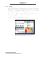
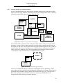
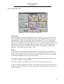
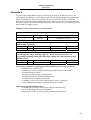
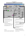
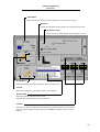
1
Department of Computer Science at Mälardalen University
Supervisor Rikard Lindell
Examiner Peter Funk
ABB Automation Technology Products
AB Robotics
Supervisor Ralph Sjöberg
Visual Programming
Simplified online programming of arc welding robots
Master Thesis, 20p in Computer Science
Department of Computer Science at
Mälardalen University, Västerås, Sweden
January 2002
Authors: Mikael Johnsson
Andreas Örmo
Visual Programming
ABSTRACT
This paper presents the result of our Master thesis work at ABB Automation Technology
Products AB Robotics, performed late 2001 and early 2002.
ABB sees the potential in the visual programming field, and is interested in investigating
if it is possible to develop something new or improved for manufacturers that have not
got the possibility or knowledge to use RobotStudio1. These customers program in the
old fashioned way; online.
The main purposes with this thesis are to show the principle of visual online
programming by making an intuitive, robust, simple and usable prototype connected to
present online programming methods, as well as to investigate the state-of-the-art in
visual programming today.
The prototype has a straightforward, intuitive user interface, and the navigation is simple.
Unneeded, advanced features are hidden and the use of necessary ones is simplified and
automated to make it possible for a wider range of people to program arc welding robots.
A user evaluation with people inside ABB is also carried out and the result about how
these people understand the prototype is presented. The result from the user evaluation
can be used as input for future development projects with focus on visual programming.
Some of the comments from the test persons were “it is a very good idea and takes the
programming phase in the right direction” and “if it works satisfactory, it is an
opportunity to entice new customers to ABB robots”.
1
http://www.abb.com/robots
I
Visual Programming
ACKNOWLEDGEMENTS
First and foremost we would like to thank Ralph Sjöberg and Lars Barkman at ABB
Automation Technology Products AB Robotics for their continuous support, guidance
and technical information. A big thank you also goes to Lars Dahlén and Henrik Lander
for giving us a good start.
We would like to thank Rikard Lindell and Peter Funk at IDt for giving us a push in the
right direction every once in a while. Thanks to Peter and Jonas at Segerström&Svensson
in Eskilstuna for taking their time to show us the production and participating in a survey.
A special thank you also goes to Lars G Karlsson and the three volunteering prototype
testers in Laxå.
Thanks to the following persons for answering our sometimes stupid questions and for
helping us getting valuable information or contacts: Göran Manske, Anders Lundell,
Henrik Ryegård, Martin Strand, Ahmed Kaddani, K-G Johnsson and Peter Herbrich.
Andreas Örmo and Mikael Johnsson, January 2002.
II
Visual Programming
LIST OF FIGURES
Figure 1 RAPID instructions on the teach pendant......................................................................... 5
Figure 2 Arc welding instructions in RAPID..................................................................................6
Figure 3 Sanscript (www.trulyvisual.com/sanscript/tour/sample.htm)........................................... 8
Figure 4 Dymola (www.radata.demon.co.uk/dymola.html) ........................................................... 9
Figure 5 Screenshot of AMIRA - the precursor of KIE................................................................ 10
Figure 6 KIE - The KUKA Icon Editor (www.kuka-roboter.de/webc/re_engl/index.html).........11
Figure 7 UltraArc (www.delmia.com) .......................................................................................... 12
Figure 8 Robotscript (www.rwt.com/RWT_Content_Files/articles/RWT_AJan99IR.html)........14
Figure 9 Schematic overview of the thesis project ....................................................................... 23
Figure 10 A comprehensive prototype description ....................................................................... 24
Figure 11 Requirement elicitation, analysis, definition and specification ....................................25
Figure 12 The waterfall model with feedback (authors’ interpretation) ....................................... 26
Figure 13 The iterative model ....................................................................................................... 26
Figure 14 Example screenshot of the process data setup design...................................................28
Figure 15 Manipulated example screenshot of the welding configuration design........................ 28
Figure 16 A schematic overview of the internal design................................................................ 29
Figure 17 Schematic of the welding configuration ....................................................................... 29
Figure 18 Schematic of the robot in the simulation phase ............................................................30
Figure 19 The seven states of the robot simulator ........................................................................30
Figure 20 The tuning module ........................................................................................................ 31
Figure 21 Schematic of the error-handling module ...................................................................... 32
Figure 22 Evaluation part 1 (Weld Process Data).........................................................................36
Figure 23 Evaluation part 2 (Welding Configuration) .................................................................. 37
Figure 24 Evaluation part 3 (Change Parameters) ........................................................................ 38
Figure 25 Evaluation part 4 (Real Time Tuning during program execution) ...............................39
Figure 26 Process data configuration on the TPU......................................................................... 50
Figure 27 Weld data parameter setup on the TPU ........................................................................50
Figure 28 Real time tuning in the prototype ................................................................................. 51
III
Visual Programming
LIST OF TABLES
Table 1 Compilation of visual programming software and tools.................................................... 7
Table 2 Common VAL commands ...............................................................................................52
Table 3 Comparison of Robot Language Syntax .......................................................................... 52
IV
Visual Programming
TABLE OF CONTENTS
1 INTRODUCTION.................................................................................................................................................... 1
1.1
1.2
1.3
2
BACKGROUND ............................................................................................................................................ 1
PURPOSE ..................................................................................................................................................... 2
DOCUMENT DESCRIPTION ........................................................................................................................... 2
RELATED WORK............................................................................................................................................ 3
2.1
BASIC CATEGORIES OF PROGRAMMING LANGUAGES ................................................................................... 3
2.2
PROGRAMMING TECHNIQUES ...................................................................................................................... 4
2.2.1
Online programming ............................................................................................................................. 4
2.2.2
Offline programming............................................................................................................................. 4
2.3
HOW AN ABB ARC WELDING ROBOT IS PROGRAMMED TODAY ................................................................... 5
2.4
STATE OF THE ART ...................................................................................................................................... 7
2.4.1
Approach............................................................................................................................................... 7
2.4.2
Compilation of visual programming software and tools ....................................................................... 7
2.4.3
General purpose prototypes and software ............................................................................................ 8
2.4.3.1
Sanscript........................................................................................................................................... 8
2.4.3.2
Dymola ............................................................................................................................................. 9
2.4.4
Visual programming software concentrated towards the robot process industry............................... 10
2.4.4.1
AMIRA – Esprit project 22646 ....................................................................................................... 10
2.4.4.2
KIE – KUKA Icon Editor................................................................................................................ 11
2.4.4.3
UltraArc ......................................................................................................................................... 12
2.4.4.4
CimStation Robotics ....................................................................................................................... 12
2.4.4.5
ROPSIM ......................................................................................................................................... 13
2.4.4.6
RobotScript..................................................................................................................................... 13
2.4.4.7
Grasp2000 ...................................................................................................................................... 14
2.4.4.8
COSIMIR ........................................................................................................................................ 14
2.4.4.9
ActWeld .......................................................................................................................................... 15
2.4.4.10
RobotStudio .................................................................................................................................... 15
2.5
CONCLUSIONS........................................................................................................................................... 15
3
VISUAL PROGRAMMING........................................................................................................................... 16
3.1
INTRODUCTION ......................................................................................................................................... 16
3.2
OUTLINE ................................................................................................................................................... 17
3.2.1
Is Visual Programming always better? ............................................................................................... 17
3.2.2
Known Visual Programming difficulties ............................................................................................. 17
3.2.3
Why Visual Programming? ................................................................................................................. 17
3.3
THEORETICAL BACKGROUND .................................................................................................................... 18
3.3.1
Programmer survey............................................................................................................................. 18
3.3.2
Researchers’ theories.......................................................................................................................... 19
4
THE PROTOTYPE......................................................................................................................................... 21
4.1
BACKGROUND .......................................................................................................................................... 21
4.2
VISIONS .................................................................................................................................................... 23
4.3
GOALS ...................................................................................................................................................... 23
4.4
APPROACH ................................................................................................................................................ 24
4.4.1
General description............................................................................................................................. 24
4.4.2
Requirements....................................................................................................................................... 25
4.4.3
Work method ....................................................................................................................................... 26
4.4.4
Graphical User Interface design......................................................................................................... 27
4.4.4.1
Issues when creating a prototype for programming arc welding robots visually........................... 27
4.4.4.2
Approach ........................................................................................................................................ 28
4.4.5
Internal design and implementation.................................................................................................... 29
4.5
PROS AND CONS ........................................................................................................................................ 33
4.5.1
Advantages .......................................................................................................................................... 33
4.5.2
Disadvantages ..................................................................................................................................... 34
4.6
USER EVALUATION ................................................................................................................................... 35
4.6.1
Evaluation results................................................................................................................................ 36
4.6.6.1 Evaluation part 1 ................................................................................................................................... 36
V
Visual Programming
4.6.6.2 Evaluation part 2 ................................................................................................................................... 37
4.6.6.3 Evaluation part 3 ................................................................................................................................... 38
4.6.6.4 Evaluation part 4 ................................................................................................................................... 39
5
FUTURE WORK............................................................................................................................................. 40
6
CONCLUSIONS.............................................................................................................................................. 42
7
REFERENCES ................................................................................................................................................ 44
APPENDIX A ............................................................................................................................................................ 48
APPENDIX B ............................................................................................................................................................ 49
APPENDIX C ............................................................................................................................................................ 50
APPENDIX D ............................................................................................................................................................ 51
APPENDIX E ............................................................................................................................................................ 52
APPENDIX F ............................................................................................................................................................ 53
APPENDIX G............................................................................................................................................................ 54
APPENDIX H............................................................................................................................................................ 55
VI
Visual Programming
Introduction
1 Introduction
Robotics has been an active area of research for more than three decades. Today various
types of robots are thus in use in industry, in particular for manufacturing applications.
Europe has a strong position in robotics manufacturing through major companies. ABB
Automation Technology Products AB Robotics1 is such a company that develops,
manufactures and distributes industrial robots. An industrial robot is a complex computer
aided system consisting of many parts. Ease of use and efficiency are strong user
demands.
ABB´s robot simulator RobotStudio2, that allows manufacturers to program their next job
without interrupting the one currently in progress, is starting to attract considerable
attention from both large and small companies. In some cases, it is halving the time for
products to come to market and is cutting costs by up to 30 percent, according to
customers3.
This is the reality today. Customers, large or small, that have the funding, knowledge and
technique use the latest technology. Virtual programming with RobotStudio allows
companies to accept big contracts that would have taken a robot off the daily grind for
long bouts of manual programming and testing.
In order to achieve simplification and efficiency in future use of arc welding robots, there
is a need to investigate the possibilities to make use of a graphical description of the
controlling program, as well as the process information. To create a graphical description,
visualization, lies within the boundaries of something called Visual Programming4. VP
research is a very wide concept with many concentrations, of which only a few are of
interest in this case; fundamental research, industrial research in general and, if possible,
special attentions towards the robot process industry.
1.1 Background
The majority of all visual robot-programming tools today are offline based. The big
customers (e.g. car factories) are ready, and able, to invest money in expensive offline
programming computers and programmers, and they have great use of pre-programming
the robots for the big-scale production they provide. However, not all customers benefit
from such systems. The smaller companies have maybe a single up to a few robots at
their disposal, intended for a small-scale production. In their case, investing in expensive
offline programming equipment is not really an option. Even if it was, once the
equipment is in place, all work cells and materials need to be modeled, there must be an
educated operator to do this, and so on. This gets very ineffective, considering the small
quantities they produce, perhaps down to a single piece. The solution for them is to use
online programming. Nevertheless, this also needs programming knowledge to perform.
In relation to this, there are a large number of potential customers that also might use a
robot if it was easier to program and maintain.
1
For the remainder of this paper, ABB Automation Technology Products AB Robotics will be referred to as ABB
Robotics
2
http://www.abb.com/robots
3
http://inside.abb.com (published 011119)
4
For the remainder of this paper, Visual Programming will occasionally be referred to as VP for short
1
Visual Programming
Introduction
1.2 Purpose
The purpose with this thesis is not to create as much functional program code as possible,
nor to build a fully functional application. Instead it is of importance to show whether it
is possible or not to build an intuitive, simple and straightforward application using visual
programming for the robot arc welding industry, and to make this process easier on the
user. This is attempted with a prototype.
Another purpose is to present a summary of the best visually aided software applications
available on the robot programming market up to date; in other words a state-of-the-art
investigation.
1.3 Document description
The chapters are intended to be a chronological journey through our work. Starting at
chapter 2 with a short background of different techniques used in robot programming
today. Chapter 2 continues with the state-of-the-art investigation, followed by visual
programming theories in chapter 3. Chapter 4 describes the prototype, including a user
evaluation. The following two chapters are very important as they summarize, draw
conclusions and give the reader ideas on future work in this subject.
Chapter 1
INTRODUCTION. This chapter introduces the reader to the thesis,
background, purpose and limitations.
Chapter 2
ROBOT PROGRAMMING TODAY. This chapter describes the two main
categories of programming techniques used in robot programming today.
A brief description of how robots are programmed using RAPID is also
presented. Finally there is a presentation of some visual programming
tools on the market today.
Chapter 3
VISUAL PROGRAMMING. This chapter introduces the reader to the
visual programming domain. It starts with a general discussion of
advantages and disadvantages with visual programming, followed by a
theoretical background.
Chapter 4
THE PROTOTYPE. In this chapter a prototype with the requested
functionality is presented. It ends up in a few conclusions and a user
evaluation section.
Chapter 5
FUTURE WORK. This chapter gives proposals on future work.
Chapter 6
CONCLUSIONS. This chapter draws conclusions over the thesis work.
2
Visual Programming
Related work
2 Related work
The idea to this assignment is based on an earlier bachelor degree, “En studie av Visuell
robotprogrammering” [27]. A free translation is “A study of Visual robot programming”,
and it was intended to investigate the possibility to extend the textual programming phase
with graphics and images.
A prototype was developed during this project as well. It uses a flowchart model to create
arc welding programs, and a combination of buttons, icons and textual input in a
windows-like environment to let the user set up necessary parameters.
2.1 Basic categories of programming languages
Virtually all robots are programmed with some kind of robot programming language.
These programming languages are used to command the robot to move to certain
locations, signal outputs, and read inputs. The programming language is what gives
robots flexibility. When learning any programming language, be it a robot language or a
computer language, one of the most difficult tasks is learning what the commands are and
how to use them.
To get an overview of different types of robot programming languages, it is appropriate
to put them in three basic categories:
1. Specialized robot languages. These languages have been developed specifically for
robots. The commands found in these languages are mostly motion commands with
minimal logic statements available. Most of the early robot languages were of this
type, although many still exist today. VAL1 is an example of such a robot language.
2. Robot library for a new general-purpose language. First creating a new generalpurpose programming language and then adding robot-specific commands to it
created these languages. They are generally more capable than a specialized language,
since they tend to have better logic testing capabilities. KAREL2 is an example of this
type.
3. Robot library for an existing computer language. These languages are developed
by creating extensions to already existing popular computer programming languages.
Consequently, the robot languages resemble traditional computer programming
languages, providing the same power as these widely used languages. RobotScript3 is
an example of this type of language.
1
See [Appendix E - Table 1] for code example
KAREL is a robot programming language from Fanuc Robotics, see [Appendix E - Table 2] for code example
3
See [Appendix E - Table 3] for code example
2
3
Visual Programming
Related work
2.2 Programming techniques
Today, arc welding robots are programmed in one of two possible ways. In reality, these
techniques are often combined, which sometimes is referred to as hybrid programming.
The two main techniques are described shortly below.
2.2.1 Online programming
Online programming means creating the control program directly on the robot’s onboard
computer, hence by manually steering the robot to different positions using a jog1 or
similar control mechanism. Each desired position contributes to the code as a number of
coordinates. An advantage with online programming is exactness and few later
corrections due to programming the actual robot in its actual real-world environment.
Time consuming and long production stops are mentioned as disadvantages.
2.2.2 Offline programming
In contrast to online programming, offline programming means creating the control
program on a detached unit, such as a PC. This involves either manual editing of code in
a text editor, or automatically generated code using for instance a CAD-model in
RobotStudio2 [47] or corresponding environments. Once the program is ready for
deployment, it is moved to the robot’s computer for manual correction and tuning. An
advantage with this method is that robots can be programmed before installation and stay
in production while being reprogrammed, meaning production breaks usually are
significantly shortened. On the other hand, manual correction sometimes gets very
extensive, and a programmer is also required to write the code offline.
1
2
A jog is a joystick for manual control of a robot
RobotStudio is a software environment created by ABB for program development, simulation, code generation, etc
4
Visual Programming
Related work
2.3 How an ABB arc welding robot is programmed today1
This section of the chapter works as a short introduction to understand the principles of
how to program an online arc welding robot today, and is not a complete step-by-step
guide. However, before this introduction it should be mentioned that today there are
complete solutions that simplify the programming and use of robots. These solutions are
called work cells (e.g. FlexArc Compact) and consist of a robot, welding equipment and
software, integrated in a steel cage with complete safety functionality.
Before starting to edit arc welding instructions, the arc welding system and external axes
must be configured. The arc welding data that is to be used needs to be defined as well.
This data is divided into three types:
•
•
•
seamdata: describes how the seam is to be started and ended.
welddata: describes the actual welding phase.
weavedata: describes how any weaving is to be carried out.
The exact components of the above data depend on the configuration of the robot at the
time.
Now the arc welding instructions can be added. This can be done in the following way:
1. Jog the robot to the desired destination position.
2. Open the instruction pick list by choosing IPL1: Motion & Process.
3. Select the instruction ArcL or ArcC.
The instruction will be added directly to the program, as illustrated in Figure 1. The
arguments are set in relation to the last arc welding instruction that was programmed. The
instruction is now ready for use. However, if an argument needs to be changed, it can be
replaced by another.
File
Edit
ProgramInstr
View
IPL1
IPL2
WELDPIPE/main
Motion&Proc
1(2)
ArcL\On, *, v100. Sm1, wd1, wv1, z ->
ArcL\Off , *, v100. Sm1, wd1, wv1, z ->
1 ActUnit
2 ArcC
3 ArcKill
4 ArcL
5 ArcL\Off
6 ArcL\On
7 ArcRefreah
8 DeactUnit
9 More
Copy
Paste
OptArg
ModPos
Test ->
Figure 1 RAPID instructions on the teach pendant
1
See [43] for further information
5
Visual Programming
Related work
When finished adding arc welding instructions, it is time to go on with the arc welding
topics. The topics contain parameters that define the arc welding functions:
•
•
•
•
The units used when the parameters are entered
The process functions used
The current equipment
The weldguide sensor being used
When the setup is complete, and the program is running, there are two ways of tuning the
weld data components. A short description of how to do it both ways follows.
Manual functions when program execution has been stopped
Certain weld data components (weld_speed, weld_wirefeed and weld_voltage) can be
tuned using the weld data tuning function. When tuning this way, it is always the present
value that is changed, however the original value can also be updated (i.e. it can be set to
the same value as the present value).
Manual functions during program execution
Certain data can also be tuned while it is active (i.e. when the program is executing),
however only the present values can be tuned. The original values can be altered only
when program execution has been stopped.
Example of arc welding instructions
Data for the start and end sequences of the weld
Data for the ongoing weld
Data for weaving
Arguments for flying start
of the process
ArcL\on,p1,v100,sm1,wd1,wv1,fine,torch
L = Linear
C = Circular
Arguments as in the
MoveL instructions
MoveJ p10, v100, z10, torch;
ArcL\On, p20, v100, sm1, wd1, wv1, fine, torch;
ArcC, p30, p40, v100, sm1, wd1, wv1, z10, torch;
ArcL, p50, v100, sm1, wd1, wv1, z10, torch;
ArcC, p60, p70, v100, sm1, wd1, wv1, z10, torch;
ArcL\Off, p80, v100, sm1, wd1, wv1, fine, torch;
MoveJ p90, v100, z10, torch;
Figure 2 Arc welding instructions in RAPID
6
Visual Programming
Related work
2.4 State of the art
2.4.1 Approach
As mentioned earlier, VP is a rather wide concept. In this case however, state of the art
visual programming systems are only interesting if they are applicable to robot
programming. This approach turned out to present two types of applications, hence
dividing the topic into two larger subcategories: general-purpose visual programming
software and VP tools concentrated towards the robot process industry.
2.4.2 Compilation of visual programming software and tools
SW
package
Company
Web-site
General
description
Sanscript
Northwoods Software Corporation (USA)
www.trulyvisual.com/sanscript/index.htm
Visual dataflow
programming
language
Dymola
Rapid data (GB)
www.radata.demon.co.uk/dymola.html
Modeling program
and language
Amira
KUKA Roboter GmbH (GER) et al.
www.cee.etnoteam.it/amira/frameset.html
Advanced Manmachine Interface
(project before KIE)
KIE
KUKA Roboter GmbH (GER)
www.kuka-roboter.de
Online visual
programming
language
UltraArc
Delmia (W orldW ide)
www.delmia.com
Simulation, offline
program
CimStation
Robotics
Silma (a division of Adept Technology Inc.)
www.adept.com/Silma/products/pdcimstationrobo.html
Simulation, offline
program
ROPSIM
Camelot (DK)
www.camelot.dk/english/historie.htm
Simulation, offline
program
RobotScript
Robotic W orkspace Technologies Inc. (W orldW ide)
www.rwt.com/RW T_Content_Files/articles/RW T_A
Jan99IR.html
Macro-like robot
program, visual /
textual robot
language
Grasp2000
Bygsystems limited (GB)
www.bygsystems.com/robotics/robotics_index.htm
Simulation, offline
program
Cosimir
Institute of Robotics Research (GER)
www.irf.unidortmund.de/cosimir.eng/prospekt.d/welcome.htm
Simulation, offline
program
ActWeld
Alma (FR)
www.alma.fr/cgi-bin/charge_frame.pl
Simulation, offline
program
RobotStudio
ABB (W orldW ide)
www.robotstudio.com
Simulation, offline
program
Table 1 Compilation of visual programming software and tools
7
Visual Programming
Related work
2.4.3 General purpose prototypes and software
Applications presented here are to be considered general-purpose visual programming
tools. They are intended for various industrially related tasks, such as the robot industry,
but need not be used specifically for programming robots.
2.4.3.1 Sanscript
Sanscript1 [4] is a visual dataflow programming language and development environment.
Scripts (called "flowgrams") are assembled from graphic functions connected together in
dataflow-like diagrams. Sanscript is for professionals that aren't programmers, but “need
to throw a script together now and then to get their job done”. Functions are the primary
components of Sanscript. Functions are represented by icons that include labels, inlets
(data-entry points), outlets (where data leaves the functions) and other appropriate
symbols. The icons indicate the action of the function. The pre-made functions include
drive, path, directory and file management, text and string handlers, integer and decimal
number tools, system utilities and user-interface components. There are also functions for
working with the Windows Registry, data lists, and compound data records. Sanscript
also includes functions for OLE/DDE that provide a mechanism to work with objects in
other applications. There are over 200 functions provided.
Figure 3 Sanscript (www.trulyvisual.com/sanscript/tour/sample.htm)
1
Developed by Northwoods Software Corporation (USA)
8
Visual Programming
Related work
2.4.3.2 Dymola
Dymola1 [5] is described as both a general purposes modeling program and language,
appropriate for building all sorts of mechanical and electrical systems. It has an objectoriented approach, enabling several of the powerful characteristics of such languages, e.g.
hierarchical structures, model classes and even inheritance.
Dymola is built on using equations for describing modeling details. The equations are
automatically solved and interpreted to symbolical representations. These models and
symbols can then be generated on different formats. Supported at the moment are,
amongst others, C and Fortran.
Dymola is available for the UNIX and Windows platforms.
Figure 4 Dymola (www.radata.demon.co.uk/dymola.html)
1
DYnamic MOdeling LAnguage by Rapid Data (GB)
9
Visual Programming
Related work
2.4.4 Visual programming software concentrated towards the robot process industry
This section contains visual programming software directly aimed for the robot process
industry.
2.4.4.1 AMIRA – Esprit project 22646
In November 1996, KUKA1 lead the way for cooperation among five European
companies, with the intention “to develop the next generation of advanced man-machine
interfaces for robot system applications”. The project was called Advanced Man-machine
Interfaces for Robot System Application, or AMIRA [6 & 46] for short, and proceeded
until spring 1999. Some of the keywords were “a visual language for robot
programming”, i.e. a tool that allows the end-user to create programs on a higher level
than with the usual commands and instructions used in text based languages like e.g.
RAPID. The result was a visual programming environment on a point-and-click basis that
was “tested and verified in industrial environments”, and thus created the foundation for
the KIE2.
Figure 5 Screenshot of AMIRA - the precursor of KIE
1
2
KUKA Roboter GmbH (GER), founded 1898 in Augsburg
[2.4.4.2 KIE – KUKA Icon Editor]
10
Visual Programming
Related work
2.4.4.2 KIE – KUKA Icon Editor
Based on the AMIRA project, KUKA developed an online visual programming system
called KIE [7]. As with its successor, the idea is to relieve the end-user from syntactic
work, and focus on the higher-level logic and task goals.
Instead of writing lines of code in a text editor, the ‘programmer’ selects the proper icon
and inserts it in a flowchart-like environment. KIE also allows direct manual (textual)
manipulation of the code to satisfy needs of both beginner and experienced programmers.
Considering that KIE uses icons to represent programs, there is a risk (as with all visual
graphic environments) that the working space might become very immense and detailed.
In an attempt to maintain the overall picture no matter the complexity of a program, KIE
also features an overview window with zooming functionality.
Figure 6 KIE - The KUKA Icon Editor (www.kuka-roboter.de/webc/re_engl/index.html)
11
Visual Programming
Related work
2.4.4.3 UltraArc
UltraArc1 [8] is a simulation and offline programming solution, with calibration tools that
let users adjust the simulation model to accurately reflect real world device relationships.
The interface lets programmers easily modify robot devices to achieve very accurate
robot motion results.
UltraArc holds a library of arc welding robots and weld guns, including the latest robots
from ABB, Fanuc and Motoman. It also includes a built-in CAD package to create
custom work cell components and supports direct import of CAD files via IGES, DXF
and direct translations. Robot programs can then be automatically generated from
information contained in weld details. There is also support for robot controller-specific
weld process information (seam tracking, seam searching, speeds, currents, voltages, etc).
Figure 7 UltraArc (www.delmia.com)
2.4.4.4 CimStation Robotics
CimStation Robotics2 [9] is a program much like RobotStudio. The major difference
between these two products is that CimStation supports many different robot suppliers
and their products.
1
2
Developed by Delmia (worldwide)
Developed by Silma (a division of Adept Technology Inc.)
12
Visual Programming
Related work
2.4.4.5 ROPSIM
This virtual production system is a result of a research environment at DTU1 and IKS2,
after further development by Camelot3.
ROPSIM [10] is a PC based, model driven robot simulation system with 3D
visualization. The simulation is performed virtually and allows production simulation on
screen. It is a robot programming system for use in design, layout, production and
maintenance of work cells in integrated production systems.
ROPSIM is:
•
•
•
•
Developed for Microsoft Windows
Able to reuse CAD models and simulate 3D robot programs
Drag 'n drop programming
Robot supplier independent
The program has been developed with the focus of simplifying offline programming of
robots. Programming is graphical and supported by CAD models. It has a projectoriented approach. Models and robot programs are combined in projects for easy program
usage. ROPSIM is open for integration with third part software. In ROPSIM, programs
can be built in two different ways: interactively graphically or textually. Interactive
programming is utilized for programming of movement, while program logics are
programmed using the latter.
ROPSIM has interfaces for several robot vendors’ controllers. The interface can consist
of a text file on a disc, a network connection or through direct communication via the
serial port of the PC. In other cases a post processor is used so that robot programs
developed in ROPSIM can be transferred to the robot's controller.
2.4.4.6 RobotScript
RobotScript4 [13] should get a category of its own, since it is not really a graphical
environment for visual programming itself. Code is produced textually, but because it
operates in a Windows environment, the end-user has the advantage of using any thirdparty software to enhance the operation of the robot cell. It also provides an intuitive,
graphical user interface to reduce operator training and minimize errors. It can easily be
customized using the Software Development Kit to provide a standard, enterprise-wide
operator interface.
RobotScript is a macro-like robot programming language that employs the Microsoft
ActiveX-technology, and is actually based on Microsoft's Visual Basic Scripting
programming language. Consequently, RobotScript can be used in a variety of Microsoft
development environments, including Visual Studio, Office or any Windows
development environment.
1
The Danish Technical University
The Institute for Construction and Controlling technique
3
Camelot Development (Denmark)
4
Developed by Robotic Workspace Technologies Inc.
2
13
Visual Programming
Related work
RobotScript is used to program virtually any robot model that is being controlled by the
URC1. It runs in online mode in the Windows NT environment on a company's URC, or
in offline mode on any PC running Windows NT/95.
Figure 8 Robotscript (www.rwt.com/RWT_Content_Files/articles/RWT_AJan99IR.html)
2.4.4.7 Grasp2000
Grasp20002 [15] is another software application in the vast category of visual robot
programming systems that support 3D models created with CAD tools. The system exists
in two versions; one basic version supporting most common robots and robot
programming languages, and another version developed together with Toshiba
specifically for their robots.
In addition to ‘standard functionality’ among this kind of products, such as collision
detection, reach validation and numerous system checks, Grasp2000 claims to be offering
features that other offline programming systems do not; extraordinary calibration
software for calibrating the 3D model and mapping it onto the real world. Further it needs
no external measuring equipment to be set up, but requires only a few robot poses as
input for calibration and analysis.
Grasp2000 is available for the Windows and UNIX platforms.
2.4.4.8 COSIMIR
COSIMIR3 [11] is a 3D-robot simulation system much like RobotStudio. It can be used
to check position reachability of all positions, as well as plan and simulate whole work
cells. This means that not only robot motion, but also the interaction of the robot with the
environment (e.g. gripper and transport actions) is realistically simulated.
COSIMIR supports several robot programming languages, for instance IRL, V+, KRL,
RAPID, MRL4 etc, and can generate programs in the chosen programming language
automatically.
1
Universal Robot Controller is an open-architecture, PC-based robot controller
Developed by Bygsystems limited (GB)
3
Developed at Institute of Robotics Research (GER)
4
Industrial Robot Language, Kuka Robot Language, MovemasteR Command
2
14
Visual Programming
Related work
Its structure is modular and can be configured with different packages and modules,
making it possible to extend COSIMIR for new requirements, e.g. by adding additional
modules for further programming languages or for the up- and download from/to specific
robot controllers.
2.4.4.9 ActWeld
ActWeld1 [14] is an offline programming development environment that, similarly to
amongst others RobotStudio, imports CAD/CAM-models to allow for the programmer to
program the robot graphically. ActWeld supports basically “all robots in the market”, and
claims to be able to take all necessary parameters into consideration.
2.4.4.10 RobotStudio
RobotStudio is ABB’s own software tool for simulation and offline programming of
robots. It is built on the ABB VirtualController, an exact copy of the real software that
runs the robots in production, and hence provides very realistic simulations, using real
robot programs and configuration files.
2.5 Conclusions
The extensive search for different modern visual robot programming environments
provided a voluminous number of interesting software applications, that confirm what
was stated in [1.1 Background]; a majority of them are offline based. A closer look at
each one of them shows that many of them are very similar to each other, in many
respects. The use of imported CAD/CAM-models with possibilities to simulate
movements and generate code by graphically manipulating the model is a popular
approach, as seen in RobotStudio, ActWeld, CimStation Robotics, UltraArc, etc. These
different products could basically have been put under one headline, which is why not all
of them have been described in detail.
Visual online arc welding programming tools on the other hand seem to be rare, the Kuka
Icon Editor2 excepted. A probable explanation is that successful research within this new,
“hot” area is not presented to the public, at least not on the Internet.
1
2
ActWeld is developed by Alma (FR)
[2.4.4.2 KIE – KUKA Icon Editor]
15
Visual Programming
Visual Programming
3
Visual Programming
3.1 Introduction
VP has been an area of interest for quite some time. Research can actually be said to have
been going on since the sixties, depending on exactly what is meant by ‘Visual
Programming’. What is really meant by the expression? For instance, autonomous robots
(agents) that are able to interpret information gained through a camera are considered
being visually programmed among some people. The expression itself often, and
incorrectly, leads the thoughts to textual programming using visual environments, as for
instance in Microsoft Visual Studio.
True visual programming researchers refer to VP as a method for creating whole
programs using nothing but visual building blocks, implying nothing less should be
called visual programming; no textual editing necessary, because there is often no
generated code at all to edit. Menzies suggests a definition for what pure visual
programming is: “A pure VP system must satisfy two criteria. Rule 1: the system must
execute … Rule 2: the specification of the program must be modifiable within the
system’s visual environment … more than just (e.g.) merely setting numeric threshold
parameters“ [16]. Gorgan ignores the execution rule and defines visual programming like
“the visual programming notion means the developer or programmer uses visually built
up expressions in the programming process … For example, the syntactic forms are built
by picking up the terms from graphics scene. If the syntactic forms and generally all
program entities (i.e. statements, expressions, data structures, flow control structures, and
so on) have visual presentations, then the programming language is visual programming
language” [23]. Another idea of difference between visual and textual languages is
multidimensionality, as expressed by Burnett [29].
In the case of investigating visual programming as a method for programming industrial
robots, the pure visual programming approach seems tempting. However, at present time
that is a very difficult goal to achieve, and a more realistic path would be a combination:
a robot program is created using visual programming exclusively, but the programmer
still has the opportunity to make necessary, final corrections on a lower (textual) level.
Without taking any of these thoughts into consideration, visual programming could
probably be summed up with one word: usability. Usability is a word with many
definitions. However, its basic meaning is about making it easier and faster for a user to
learn, use and master something, in this case a software tool. Hence, making it easier on
the end user, perhaps by creating an interface between computer and human that is more
appropriate to us than the classical console/textual standard, is basically what visual
programming is all about.
16
Visual Programming
Visual Programming
3.2 Outline
3.2.1 Is Visual Programming always better?
Whether programming visually really helps programmers or not has been lively debated.
Results from studies and reports show very differing, at times even contradictory results
[16]. Some researchers mean that they help to some extent, but are far from always
superior to textual languages [19]. Others mean that TLs1, including fairly new objectoriented ones like Java, already are on the edge of being obsolete, due to being to C-like,
low-level and complex, suggesting they should be replaced by flowchart-like
programming methods [20].
3.2.2 Known Visual Programming difficulties
There are a number of problems with programming visually that are known to VP
researchers. One is the lack of desktop space, meaning visual representations of programs
tend to quickly become very big. In addition, many visual environments use arcs to
connect nodes (flowchart-style), resulting in lines going back and forth across the
screen2; the combination of the two makes overviewing hard.
An issue that VP researchers often have to struggle with, is the difficulty of proving any
of their theories in real life; it is hard to do reliable surveys to back them up, leaving a
great need for empirical results on whether visual representations improve the
programming process or not. This is a well-known problem in the VP community, also
referred to as the evidence problem [24].
Another problem, that might seem peculiar and irrelevant, is the classical resistance
among programmers to adapt to new programming techniques, and in particular the use
of visual ones. Brooks writes, regarding graphical and visual programming for software
development: “Nothing even convincing, much less exciting, has yet emerged from such
efforts. I am persuaded that nothing will.” [17]. O’Brien agrees by writing “…beware the
claims of visual programming. Drawing lines between objects becomes bafflingly weblike. Purely visual programming is not yet and may never be viable.” [18]. These extracts
are just examples to show a bigger picture, so on the contrary, it is of great importance to
take this issue into consideration when developing visual programming environments.
3.2.3 Why Visual Programming?
Despite present difficulties and problems to solve with VP, it is still necessary to consider
the opportunities in a longer perspective. In the perfect case, the programmer’s job is
made significantly easier. With syntactical problems removed, the programmer can focus
on program design and what the program is supposed to do – the semantics. This should
lead to a reduced development time, but at the same time improved software qualities.
1
2
For the remainder of this paper, textual languages might be referred to as TLs
This problem is sometimes referred to as the spaghetti plate syndrome
17
Visual Programming
Visual Programming
3.3 Theoretical background
There are a few difficulties doing theoretical research on VP. To begin with, there seems
to be almost an inner circle of researchers, who seem to attend every meeting or
conference available, and whose names are repeatedly cross-referenced from each other’s
papers and journals. Put differently, a majority of the documents concerning visual
programming tend to be influenced by a minority of people - in one way or another. It is
hard to tell what impact this may have on the results presented. Moreover, many of the
theories stated do not have proper experimental studies to back them up (also implied by
[21 & 22]); they are merely opinions or visions of the author1.
Based on these conditions, the theoretical research presentation is presented as actual
studies results on one hand, and authors’ theories on the other.
3.3.1 Programmer survey
“The Outlook from Academia and Industry” is an extensive survey from 1997. It presents
some interesting differences in opinion among different categories of people, including
professional traditional programmers who are known to dislike new programming
techniques, and especially visual ones.
Three different categories of intended VP users participated in one survey each: academic
VP researchers with vast knowledge of visual programming languages, professional
programmers with none or small VP knowledge and strict LabView2 programmers. The
three different surveys were constructed to provide comparable results (but here the
LabView part is left out3), presented in 15 categories with regards to visual programming.
These were of type learnability, productivity, readability, etc. A summary of the most
interesting categories follows.
General impact refers to whether visual programming languages4 are easy to use. The
academic VP researchers agreed that is the case, while half of the programmers claimed
VPLs do not make a difference on the matter, or are even more difficult to use.
Learnability is how easy something, in this case a VPL, is to comprehend and learn how
to use. The difference of opinion showed once again, when the researchers repeatedly
pointed out this VPL-benefit. The programmers however stated the time that would be
required to learn a visual programming language, if they at all mentioned it.
Productivity. The paper says (quote) “…productivity improvements are the only
justification for any investment in new programming techniques.”
Both categories agreed that visual programming could increase the amount of code
produced. However, unlike the VP researchers, the programmers disagreed that there also
were advantages to design, debugging and maintenance as well, implying that the overall
project benefits were less.
1
See [3.2.2 Known Visual Programming difficulties]
LabView is a visual programming environment
3
The third survey questions were directly aimed at LabView and can be misleading in this theoretical discussion
4
Visual programming languages might be referred to as VPLs
2
18
Visual Programming
Visual Programming
Readability. Both categories more or less agreed in this matter, that the structure is easier
to follow in visual than textual programs. This may be worth noticing, since the
programmers have little or no experience of VPLs. They referred to flow-chart diagrams
and models in general, while the researchers more specifically pointed out the advantages
of specific languages.
Documentation effects. Respondents from both categories stated that visual
representation works directly as documentation, as well as a communicating medium
between developers and customers. This is in line with Baroth and Hartsough’s opinion
several years earlier, quote “The most important advantage … in using visual
programming is the support for communications among the customer, developer, and
hardware … Without the visual component, the support for communications is not
present” [28].
Syntax reduction and modularity. Although the researchers did not seem to think about
less syntax problems as a big benefit with VPLs, it was pointed out clearly by several of
the programmers. However, a few worried about syntactic problems using visual
programming languages as well (e.g. the spaghetti plate problem).
The surveys were summarized using different codes, to get both numerical and theoretical
conclusions. The overall picture confirms the well-known classical resistance and
skepticism among traditional programmers against new programming techniques, no
matter the advantages they may contribute with. Less powerful, less readable and less
enjoyable to use were a few of their strongest arguments. The academic researchers had
almost exclusively good things to say about VP, using positive influence on the mental
process of the programmer as their best argument.
3.3.2 Researchers’ theories
The following chapter describes different researchers’ theories from the VP literature.
The intention is to reproduce their theories as good as possible so that the reader can get a
good overall picture about the different thoughts reported in the vast VP literature.
As mentioned before, there are very different opinions whether VP really improves
programming in the ways that are claimed. There are three camps of researchers in the
matter; those who are truly devoted to VP and all of its benefits, those who are very
suspicious, skeptical and critical, and then the people in between, merely reporting
others’ statements.
Hirakawa belongs to the positive group, claiming “When we use visual expressions as a
means of communication, there is no need to learn computer-specific concepts
beforehand … which enables immediate access to computers even for computer nonspecialists… ”. He continues by stating that pictures are superior to texts by being more
easily comprehensible and universal [30]. This is in line with Gradman's thoughts. He
thinks the mind does not have to interpret a picture, since it already is in terms the mind
can comprehend. He goes even further than Hirakawa when stating that "VP is such a
powerful paradigm that a user does not even have to be a programmer to learn how to
write applications. The universality of visual language ... makes programming something
anyone can learn and do" [26]. Others oppose statements like these, and refer to the lack
19
Visual Programming
Visual Programming
of evidence supporting them [40 & 41]. Still a decade later, that is an unfortunate truth;
hard evidence is rare.
Other typical statements are that VP is more user friendly, helpful, satisfying, intuitive
readable, familiar, appealing, accessible, reliable, pleasant, straightforward, alluring,
immediate and obvious than other programming techniques. Some researchers even
believe that VP is easy to learn, easy to use, to write, understand and modify even
without training. However, as with VP in general, there is little research that has
investigated the relative speed of learning to program, and a claim of competence without
training whatsoever seems unlikely [25].
According to Chang et al it was often stated that people find it easier to deal with the
concrete than the abstract; solutions are easier to perceive if abstract information is
converted to a concrete (i.e. visual) form [39]. Brown and Schiffer agree to this by
pointing out that pictures are good at showing abstraction [38], or communicate a higher
level of abstraction [36]. In addition, there is extensive general research showing that
concrete words are easier to remember than abstract ones [31], while others say that
abstract data is challenging for visual programming exactly because it is not naturally
visual [37].
In a study, Blackwell noticed that several writers have mentioned how VP helps to
express problem structure [25]. This was implied earlier by Schiffer, stating that
relationships are more explicitly represented and easily recognized in pictures than in text
[36]. These theories have further support in Larkin and Simon´s cognitive model of
diagram use in problem solving, where locality and topological connections between
elements reduce the need to label corresponding items [35].
Another thing Blackwell points out is that graphical information is more intuitive than
text, that it enables use of “native intelligence” [34] and provides for “intuitive
interaction” [33]. The fact that something is intuitive will make it easier to understand, in
other words meaning that graphical presentations are more comprehensible [32].
20
Visual Programming
The prototype
4 The prototype
4.1 Background
ABB1 recently finished an investigation among 250 ABB customers in ten countries
worldwide. Although the customers seem to have confidence for the company, the results
show that ABB is not generally associated with user friendliness.
To get an objective idea as possible about robotic arc welding, robots in general, robot
programming, usability, problems and other important background facts, we have tried to
get input from different points of views. This means we do not only want to know what
people in the robot developing business think, but also what the end user on the factory
floor has to say about it.
A field trip to Laxå, with the intention to hear about their development, goals, visions and
expectations, also gave us an opportunity to see arc welding in their laboratory. A number
of issues and problems regarding tuning and welding results became obvious during the
demonstration.
This was followed up by a visit at Corporate Research in Västerås. They are developing a
way to simplify the welding process as well. This relieves us from a few parts, since we
now can assume these already exist. In addition, we were inspired by the way they
presented the program information visually. However, once again we were reminded
about the difficulties in robotic arc welding.
To balance these experiences, we visited Segerström&Svensson in Eskilstuna. They have
a number of welding robots from ABB and Motoman. We made an interview with one of
the people involved in programming/maintaining the weld robots. In addition to this
interview, a small end-user survey was performed. The results provided us with a few
interesting thoughts and even some concrete programming problems. A compilation of
these can be viewed in [Appendix A].
It should be mentioned that an effort was made to get a demonstration of the
“revolutionary” KUKA Icon Editor2. Contact was made with Peter Herbrich at DEFAC in
Germany, but unfortunately nothing could be arranged.
1
2
The investigation was commissioned in late 2001
[2.4.4.2 KIE – KUKA Icon Editor]
21
Visual Programming
The prototype
In addition to this input, we have discussed these issues with several people at ABB
Robotics. To summarize, there seems to be a general opinion that online programming of
ABB arc welding robots today is unnecessarily difficult. A few main aspects of what
these difficulties include (in no particular order):
•
The programmer needs extensive knowledge about RAPID. Commands, syntax,
function parameters, semantics and so on.
•
The programmer needs to know how all parameters affect the welding result, which
means he/she also needs to know a lot about welding.
•
A company might be using several different robot fabricates. This means a robot
operator would have to know several totally different programming languages as well.
•
Tuning of welding parameters such as voltage, welding speed and wirefeed speed
during welding means walking through several drop-down menus. Once the tuning
menu is reached, the parameters can only be tuned one at a time. By the time all
parameters are tuned, there is a good chance the robot is done welding a long time
ago.
•
The interface on the teach pendant1 is generally not very usable (user friendly). There
are several steps that should be avoidable in doing simple tasks such as programming
and tuning.
•
To change certain data for a welding program, such as the burnback time in the seam
data or the wire diameter, the programmer has to walk through all files in the program
and set it at every single location.
•
Defining welding points by manually ”jogging” the robot is not easy, nor effective.
Even so, this is still the most common way to do it.
•
Today a program can be created by up to three different people. The following could
be a totally possible scenario: one man defines a rough path, making sure the robot
will not collide with any objects. The next one creates a more exact path, setting
coordinates and angles the way they should be. The third person has vast knowledge
about welding, so he/she sets up all welding parameters, such as weld data, seam data,
weave data, etc. The natural reaction to this is that one person could do all of it if it
would not demand him to know everything about both programming and welding.
All of this implies that there is a need to create a simple tool to let smaller customers
program robots with extreme ease. The everyday user has a need for approximately 20
percent of all programming functionality available. The rest is considered unnecessary
and even confusing. One approach to supply this might be to create a much simpler and
more limited tool that allows for visual programming, and that has enough power to
perform all actions needed for the small user.
1
A teach pendant is the operator’s handcontroller to program and operate the robot
22
Visual Programming
The prototype
4.2 Visions
Visions on how to program an arc welding robot in the future are many and of different
natures. Many of the thoughts are about how the programming phase can be simplified
for the end user. It does not matter if you are running a multinational company with
production all over the world, using advanced off-line programming tools in your
production, or if you run a smaller business that generally programs the robot online; a
demand these customers have in common is the possibility to handle and program the
robot in the easiest possible way.
In relation to this, ABB Robotics wants to offer their customers innovative, advanced
products that are experienced as user friendly, in the meaning that they are very easy to
learn to deal with and use. The simplification is intended to substantially decrease the
programming- and startup time considerably for the customers; an improved
programming time from e.g. 3 weeks to 3 days, or 3 days to 3 hours is by no means
impossible.
The bottom line is that a robot that is not working properly, or not working at all, means
losing thousands of dollars every minute for a multinational company and is not
acceptable in any way.
4.3 Goals
The best way to describe arc welding-robot programming today and what part of it this
thesis focuses on, is perhaps with an overview relation chart:
Simplified robot programming
Simplicity
Programming &
Offline programming
Customer must have computer
knowledge
Synergism between these two
administration
All functionality
Online programming
Simplified programming:
80 %
•Path programming (skip)
•Process programming
•Logical programming
20 %
Find the most important functions in arc welding
for the small user and improve the usability for them.
Visual programming
(graphical)
Figure 9 Schematic overview of the thesis project
The nodes “Offline programming” and “Online programming” describe the two ways of
programming arc welding robots today. This thesis focuses on the process and logical
programming parts in the “Online programming” node, not including path programming
issues. From these parts, one objective is to extract the most important robot
programming functionality and provide a new, visual interface. This could improve
usability and widen the user clientele to include non-programmer welders on one hand,
and non-welding programmers on the other. Another possible outcome might be to point
out some sort of synergism between offline and online programming in general.
23
Visual Programming
The prototype
4.4 Approach
4.4.1 General description
Prototype Description
Preparation
Transfer code to robot
Execution
The simulated robot ”executes” the code by
changing states. It can be manipulated from
the tuning panel. Based on internal relational
probability percentage errors occur, and
generate error events. The operator gets an
error description and can then take necessary
actions to correct them.
Robot
(simulated object)
Code
Errorhandling
State: welding
Generate code
I/O
Configuration
Tuning and visual feedback
1
2
3
Setup
Progress
4
Figure 10 A comprehensive prototype description
The prototype can be thought of as five parts:
1. The first part is a weldpoint editor that really has nothing to do with the prototype
itself. Its only purpose is to create a few virtual points in 3D-space that are necessary for
testing of the following parts of the prototype.
2. The second part consists of four steps, of which three are unavoidable to the user.
These steps let the user set up the weld process parameters as well as robot specific data,
such as work angles, torch distance, speed and so on.
3. The third part of the prototype comes into action once the welding setup is completed.
This is the robot simulation phase, that is used only to show how the tuning and errorhandling modules are intended to work, and is actually just a small state machine
representing a few actions of a very simple robot.
4. The fourth part is the real time tuning1 module that is part of the robot simulation
phase.
5. The last part of the prototype is the error-handling module. This is also a part of the
simulation phase.
1
See [Appendix D] for a screenshot of the prototype real time tuning module
24
Visual Programming
The prototype
4.4.2 Requirements
Although the prototype is to be seen as an experiment to point out the possibilities and
obstacles with using a combination of words and pictures, the thoughts behind the design
should be of some interest. The final requirements used in the prototype are developed
with the help of discussions and meetings with people at both ABB Robotics and
Mälardalens Högskola. These demands actually consist of three parts: requirements,
restrictions and assumptions, however they all concern the prototype.
Taken all in all, it is implied that the prototype shall strive to fulfil some important parts
of the usability concept, such as being intuitive, effective and easy to use1.
The following model inspired the process of determining requirements:
Problem
analysis
Problem
description
Prototyping
and testing
Documentation
and validation
Figure 11 Requirement elicitation, analysis, definition and specification
1
See [Appendix B] for a detailed description of the requirements
25
Visual Programming
The prototype
4.4.3 Work method
The overall development method was inspired by “the waterfall model with feedback”.
Requirements
analysis
Validate
System
design
Verify
Program
design
Coding
System
testing
Figure 12 The waterfall model with feedback (authors’ interpretation)
The interface and logics were designed first. A storyboard was complemented by
numerous power point slides, describing the approximate appearance and interaction with
the user. The design drafts were tested on people at ABB Robotics as well as Mälardalens
Högskola. The slides were then redesigned, and tested again, until all major drawbacks
were eliminated, and the program design stage was reached.
Once the logics were in order, the internal prototype design could be put together,
providing a very good ground for the next step, the prototype implementation. The
development approach was of an iterative nature.
1.
2.
3.
Im p le m e n te d fu n c tio n a lity
N o t y e t im p le m e n te d fu n c tio n a lit y
Figure 13 The iterative model
The requirements were then portioned into modules by functionality. The base for the
prototype was created, i.e. a shell consisting of all the steps described in the general
description1 was put together, but without any contents. Functionality was then added to
the different steps in gradual stages.
1
[4.4.1 General description]
26
Visual Programming
The prototype
Along with added functionality, the prototype was repeatedly tested on the same people
at ABB as the design sketches were. The testers’ comments were then taken into
consideration when modifying the prototype.
4.4.4 Graphical User Interface design
4.4.4.1 Issues when creating a prototype for programming arc welding robots visually
There are a lot of things to take into consideration when trying to make the programming
phase easier on the end user. For starters, we should think about who the end user is; what
is his/her background like? Did he or she know about programming or welding before
he/she started using this workstation, or is he/she working on a self-teaching-basis? Can
he/she read? That might seem like a stupid question, but the truth is that not all countries
have well-educated labor. Anyway, depending on the answers, the user has totally
different needs and demands on the system. An advanced and experienced user may, and
this was discussed earlier, prefer having access to every programming detail there is, in
order to create as fast and accurate welding cycles as possible. The user might also be an
”old school programmer”, and be very resistant to using a visual programming technique.
On the other hand, the beginner might be overwhelmed by all the functionality provided
in the programming language or the user interface.
Once decided to make the programming easier by using visual programming, there are
well known issues to think about. Can pictures replace all textual parts? Probably not.
Not all words can be described by concrete objects, and making abstract pictures can
make things even more difficult for the user. Also, if a picture replaced every word, the
screen would soon be filled with pictures high and low, making a detailed mess,
incomprehensible to the user. A related question is if a picture always makes actions
more intuitive, even if there really is an appropriate image for a word, or bunch of words?
The image alone requires a paragraph of itself. Depending on what the system is to be
used for, there are of course different demands on the picture. For instance, one could ask
how many/what colors are available on the target system. In the case of this thesis, the
fantasy is the limit, and hence such specific obstacles are removed. On the other hand,
there are more general issues that apply to all applications. What happens if the user is
colorblind? What colors or symbols are inappropriate to use for a certain culture? How
detailed should the image be to provide exactly the amount of information
needed/intended? Is the picture ambiguous?
A more concrete difficulty with a visual programming technique, is that the environment
does not fit the purpose. Weld robots usually work in very noisy and dirty environments,
and the air can be very dusty. Hence touch screens can get very difficult to interact with if
the components are too small or detailed, and the visual feedback may be difficult to
grasp.
These and other questions need to be considered when creating a visual programming
tool. This prototype gives one suggestion for a solution, however there are countless
possibilities.
27
Visual Programming
The prototype
4.4.4.2 Approach
Considering the aim of this project, to create a visual tool for programming robots, the
GUI1 design became very important.
The basic ideas were
•
big, clear components that are hard to misunderstand and easy to interact with
•
not too much detail
•
no unnecessary information showing if not wished for
•
combine images with text as often as possible
Figure 14 Example screenshot of the process data setup design
The other part of the visual design was about creating logic steps for the user.
The basics here were
•
minimize the number of steps to enhance availability and overview
•
easy navigation back and forth between the steps
•
spare the user from unnecessary walking through levels and menus
Figure 15 Manipulated example screenshot of the welding configuration design
1
Graphical User Interface
28
Visual Programming
The prototype
4.4.5 Internal design and implementation
A basic, informal design of the main objects and their connection to each other could be
made at an early stage, thanks to inspiration of how real welding robots work. A detailed
schematic design of the whole prototype looks like this:
ROBOT
Welding setup
•Parameters
•Instructions
•Weld points
WELD
CONFIG
Weld info
Weld data
•Position
•Tuned parameters
•Status
•Tuned angles
•Error code
•Error code
TUNING
•Position
INTERFACE
INTERFACE
Interruption
USER
Command
•Solution
ERROR
HANDLING
Figure 16 A schematic overview of the internal design
Not included in the schematic is the weld point editor, since it really is not a part of the
prototype. At least it has no other connection to reality than to simulate the insertion of
weld points in 3D-space, and for that reason the implementation details are not of interest
in this section. However, for each and every weld line the user added in the weld point
editor, an object is added to a list. The programming phase that then follows (named
“weld config” in the schematic above) is implemented as a wizard.
ROBOT
Welding setup
•Parameters
•Instructions
•Weld points
WELD
CONFIG
Figure 17 Schematic of the welding configuration
The user can modify the objects in the list by changing the process parameters. These
process data also lie as a ground for the automatic generation of weld data. These data are
generated using a database object, and are also stored in the object list. The object list is
then used to generate proper RAPID code for the weld setup. The RAPID code
instructions are then stored in a separate data type.
29
Visual Programming
The prototype
The simulation phase consists of the robot, the tuning and the error-handling modules.
ROBOT
FSM
ENGINE
Change state()
INTERFACE
GUI
Get next state()
Get current state()
State database
Tuning
Errorhandler
Figure 18 Schematic of the robot in the simulation phase
Similar to real life, the robot has an engine. In this case, it creates an interrupt at even
intervals, depending on the simulation speed. At each interrupt a number of calculations
and other operations are performed, before the GUI is updated and a signal is sent to the
tuning module. The robot is implemented as a simple finite state machine consisting of
seven states.
HOME
POS
Move
Arc
Arc /on
WELD
Retry failed
RETRY
Ign
WF _Erro
_Er r
ror
TSC
END
Re
su
m
e
su
cc
ess
ess
succ
TSC
Arc /off
Re
try
After service
START
Move
Er
ro
r
MANUAL
SERVICE
TSC failed
Service interval
Figure 19 The seven states of the robot simulator
It should be noted that the transition “Arc” is a generalization for both the ArcC and the
ArcL commands.
The robot starts and ends up in the HOME POS state via the START, WELD and END
states during a normal weldpart. However, depending on the selected level of simulated
error frequency, welding errors as well as other hardware failures may occur. These
errors are spread based on the internal probability of the errors appearing. For instance,
30
Visual Programming
The prototype
an ignition error is far more common than a collision, a wirefeed error occurs more often
than an empty gas tube, and so on.
If a welding error occurs, the robot tries to re-ignite twice. The chance of success depends
on what type of error it is, and the chance of success is also decreased with every retry. If
re-ignition fails, the robot tries to clean the weldgun tip in the TSC1. The chance of
success here is also depending on the type of error.
If another type of error occurs, such as an empty wire bobbin or gas tube, the robot enters
MANUAL SERVICE directly, since an attempt to re-ignite is a waste of time.
The tuning phase needs no detailed explanation of its implementation. It is to be thought
of as an application run on the teach pendant unit. It is hence merely an interface between
the user and the robot, and is best described with a schematic:
TUNING
OUTPUT
ROBOT
GUI
INPUT
Weld angle
Result
Volt
State
SYNERGY
Progress
Wirefeed speed
Drag/push
Weld speed
Drag/push
Volt
SYNERGY
Wirefeed speed
Weld angle
Weld speed
Figure 20 The tuning module
The input is sent to the robot, meaning the visual output is not updated until the next
interrupt occurs, when the robot sends the information back to the tuning module. This is
not an optimal solution for the prototype, since the delay might be experienced as if the
input was not registered, but the principle of having communication between the teach
pendant and the robot was preferred to instant output just to get a better sense of reality.
1
Tool Service Center, an automatic cleaning and recalibration tool
31
Visual Programming
The prototype
The final part of the simulation phase is the error-handler.
ERROR HANDLING
Error database
Solution database
OUTPUT
Progress
ROBOT
Error type
GUI
Solution
(suggestion)
INPUT
Resume welding
Abort
Figure 21 Schematic of the error-handling module
The error-handler is inactive until the robot enters the state MANUAL SERVICE. When
this happens, the error-handler is sent an error code. The error code indexes a small error
database to present both a visual and textual description of the problem, as well as
suggestions for remedy. The user can choose to resume the welding from the point it was
halted, or simply abort the welding process. It should be noted that it would not be
possible to implement something like this in a real system today, since the hardware (the
robot) does not support monitoring of all possible errors that can occur. For instance, it is
not possible to point out exactly that the gas tube is empty if ignition fails, as in the case
with the prototype.
32
Visual Programming
The prototype
4.5 Pros and cons
The prototype is developed in Visual Basic. It is very simple, with slightly overdimensioned components. Furthermore, it probably lacks several desirable features.
However, we still think it serves the purpose as a concrete representation of our basic
idea of how arc welding can be made easier.
This section discusses advantages and disadvantages. It is important to keep in mind that
the created application is nothing but a prototype, a suggestion for a possible solution.
This implies that not every intention or idea actually has been implemented. A feature
that is supposed to work in one way, but does not today, will not be mentioned as a
disadvantage.
4.5.1 Advantages
There are several improvements to the prototype.
•
•
•
•
•
•
•
Concerning ease of use, it has a straightforward, intuitive user interface with big
and understandable components that combine text and images.
The navigation is simple, just back and forth, which is made possible thanks to the
“wizard like” step-by-step setup.
There is topic related help available at all times
Undo and cancel options at every possible point of changing the data.
Programming arc welding robots is an advanced thing to do. There are lots and
lots of parameters that need to be set up, and set right, to get an acceptable result.
However, there are also a lot of parameters and coding possibilities that are
available, but do not need to be set up. For example, the small company with its
low quantities probably needs merely the basic features of the arc welding system.
The main idea here is to show not too much detail or information at once. The
prototype therefore hides unneeded, advanced features and simplifies and
automates the use of necessary ones. At the same time, advanced users are
allowed to manually edit the resulting RAPID code.
To relieve the user from as much low-level editing as possible, the prototype uses
a database containing welding information to generate welding parameters
depending on the users welding process setup. This provides the user with a
default setup, hopefully relieving him of editing every weldline separately.
Another suggestion for simplified use is the real time tuning phase. The prototype
provides quick access to tune the most common parameters, such as voltage,
wirefeed speed, welding speed, work angles, etc.
The intention and hope is that these advantages together make it possible for a wider
range of people to program arc welding robots, since a user does not have to know
everything about programming in RAPID, nor everything about the process phase.
33
Visual Programming
The prototype
4.5.2 Disadvantages
There are also a number of drawbacks with the suggested prototype, even when
unimplemented features are not considered.
•
•
•
•
1
First of all, since it was created using the “imagination-is-the-limit”-principle, the
prototype does not follow any standardized design or layout patterns.
This version requires quite some screen space, high resolution and many colors to
provide an intuitive interface. Integration with and adaption to an existing lowresolution system might decrease the usability in several ways. Designing the GUI
(images, layout, colors, etc) in a final application could hence be a difficult task if
there are strict limitations to screen size, resolution and color depth.
A possible problem of more general type is that the prototype offers a new way of
programming. This may not appeal to experienced users as desired, and was
mentioned earlier as the classical problem of “adaption resistance” among
programmers1.
Finally, not everything in the prototype would even be possible to implement on a
real system today. This depends mainly on limitations in the hardware. An
example is the error handling phase in the prototype. It presents a desired way of
handling errors and displaying the exact problem and its remedy to the user, but
the hardware today does not support this kind of sophisticated monitoring of
individual components.
See [3.2.2 Known Visual Programming difficulties]
34
Visual Programming
The prototype
4.6 User evaluation
The user evaluation was performed on three people. These test persons have very good
knowledge about robot programming and especially on how to program an arc welding
robot. This implies that the results from the evaluation give at least an indication of how
people with relevant knowledge understand the concept of the prototype.
The users were brought in one at a time. Each one of them was given a short, formal
introduction, providing them only with the background and purpose of the test. In other
words, no details or instructions on how to use the prototype were mentioned, so the user
was free to investigate and explore it in any way desired.
The evaluation method that was used is called “cooperative evaluation1”. The cooperative
evaluation method means that the users think aloud and tell the evaluator about their
thoughts about what is going on, why something happened, etc. The users also tell the
evaluator how the system is understood and what can be seen on the screen and so on.
The users and the evaluator can ask questions too each other during the whole process.
With this method, the users feel more comfortable with themselves and have the courage
to criticize the system. Observation data during every evaluation moment is written down
in a protocol.
There was a surprisingly positive attitude among the testers. They were of varying age
and experience levels, but they all seemed to be inspired and encouraged by the concept
with a graphical tool for online programming. On a detailed level, there were of course a
lot of remarks on what the prototype lacks and what could be done in a better way.
However, the remarks were of very differing natures. There seems to be as many
opinions on what is useful, necessary, good, bad or stupid as there are individuals. The
remarks reflected this and were sometimes contradictory. In spite of all that, the overall
impression was that the idea behind the prototype is to take at least one step in the right
direction.
The evaluation results can be viewed in the next section, and a summary of the users’
comments during the evaluation can be viewed in [Appendix F].
1
Also known as the walk-through method
35
Visual Programming
The prototype
4.6.1 Evaluation results
The results are presented as a step-by-step presentation of the prototype with the
evaluation expectations and results to each step. Each step is illustrated with a screenshot
of the actual prototype.
4.6.6.1 Evaluation part 1
Figure 22 Evaluation part 1 (Weld Process Data)
Expectation
The idea with this step is that the user selects a parameter from each one of the available
types (joint type, gas type, wire type, wire thickness, sheet type and sheet thickness). The
concept of the pictures is to simplify and help the user to see what to do and what
happens when a button is pressed. The text over the buttons should guide the user right if
they do not understand the picture alone. A comment to this step is that it is not necessary
for the user to do the selections in a special order.
Result
1. A problem that arose was that the users thought the wire type button was actually two
separate ones, depending on the vertical line in the middle of the button.
2. Another problem in this step was hesitation on what to do and how to interact with the
program.
3. Confusion whether the selections need to be done in a certain order or not.
Action
It is a small problem and can be solved easily with education of the users.
36
Visual Programming
The prototype
4.6.6.2 Evaluation part 2
Figure 23 Evaluation part 2 (Welding Configuration)
Expectation
The idea behind the “welding configuration” phase is that the user gets an overview of
the most important generated welding parameters without taking the risk of accidentally
changing them. To show only the most important parameters is in line with removing
unnecessary distracting information from the user. The user now sees two weldlines at a
time, the current and the next (following) line. These two lines are marked with black and
white colors respectively in the upper left corner image. These colors are supposed to
visually connect the lines to the black and white frames containing the weld parameter
data in the “current part” and “next part” views.
Result
1. The first reaction was silence and confusion. The users repeatedly tried to click nonbuttons and were expressively not sure how to interact with the program. However, this
initial confusion did not last for long, since all testers managed to edit and cycle through
the different weldlines after no or very little guidance.
2. Someone wondered were the voltage, wirefeed speed and welding speed values came
from, since he had not set them himself.
3. Another comment was that the word “current” was unfortunate in this context.
4. All of the testers had problems with the connection between the black and white lines
and their respective parameter frames, but after a short explanation there were exclusively
positive reactions.
37
Visual Programming
The prototype
Action
More conspicuous colors were suggested though, as opposed to our attempt to please
colorblind users. After getting familiar with the configuration layout, the users’
comments were very encouraging.
4.6.6.3 Evaluation part 3
Figure 24 Evaluation part 3 (Change Parameters)
Expectation
In this part of the welding setup the user has the possibility to change the parameters that
have been generated in an earlier step of the program. The user can change the values for
all of these parameters, as well as change the values for some default parameters not
highlighted earlier at all in the program. The thought is that the combination of text and
images on every button helps the user to change the right parameters.
Result
1. Some of the users had difficulties understanding how to change the values for voltage,
wire feed speed and weld speed. Attempts were made to click the text beside the real
button.
2. The users never reflected over the images when trying to change values for the seam
start and seam end data, they only read the text on the button.
3. Another problem the users had in this step was with the meaning of the image where
they can change the push/perpendicular/drag angle of the weld. They did not have a clue
what value they changed when the minus or plus sign was pressed.
4. Another question the users had in this step was how value(s) were changed when
editing all parts simultaneously.
38
Visual Programming
The prototype
4.6.6.4 Evaluation part 4
CENSORED
Figure 25 Evaluation part 4 (Real Time Tuning during program execution)
Expectation
The idea is to gather the most common (or commonly wished for) real time tuning
options in one single window. Intuitive interaction and clear visual feedback for every
interaction were also kept in mind during design.
Result
1. The first thing that was commented was simply the great idea of having all tuning
options in one place, accessible during the whole welding process. In connection to this
the testers mentioned how difficult it is to switch to tuning and actually have time to do
any tuning with the current system.
2. Another appreciated aspect was the possibility to tune angles in real time. None of the
testers had any visual interaction or comprehension problems at all, however it was stated
that the synergic tuning feedback via a plotted curve might be too advanced for the
common operator. Positive remarks were given to the result calculation. The actual
response to the tuning phase was rather close to the expected response.
39
Visual Programming
Future work
5 Future work
Proposals for future work:
•
The visual interface: should be designed by expert designers/graphic artists to reach the
best results. Component design is more difficult and important than often given credit for.
Better dynamics in the visual feedback is also desirable.
•
The path programming phase: the latest technique should be used to get the weld
points into the system. A gyro pen, which unfortunately merely is a future technique at
the moment, or some similar technique is optimal, and was also referred to in the current
prototype. Visualization of these weldpoints is also interesting since it, if combined with
the possibility to configure weld data by selecting/deselecting them by touch, gives the
user an even more intuitive and powerful tool.
•
The tuning phase: better synergy tuning opportunities and possibility to tune the weave
data as well as to adjust the weld gun diagonal offset to the weld point for improved
results.
•
The error handling phase: an error handling system that monitors and indicates
different weld, collision and process errors to the user, and in similarity to the prototype
introduces some kind of solution proposal for the error. A proposal for such a system to
visualize and remedy the arisen error is to use some kind of wizard similar to that in a
photocopier.
•
Measurement standards: functionality not implemented in today’s prototype is inches
as complement to millimetres, amperes as complement to meters per minute, etc.
•
Help functions: Extended, more detailed, case-based help functionality at all times.
•
More automation: an improvement to make the prototype more usable and powerful,
and to decrease the amount of thinking for the user, is to extend the database support for
different joint-, gas-, wire- and sheet types.
•
The RAPID code: integration with the common RAPID editor for manual code editing
and consequently also a RAPID code generator, as glanced at in the prototype, are needed
to manually fine-tune the welding program.
•
A suggestion for a future thesis: investigate if there are any possibilities to use a
combination of different techniques to simplify robotic arc welding. Such a combination
is gesture based visual programming, which should be interesting in a few years when the
technique is sufficient.
40
Visual Programming
Future work
•
A new idea: during the progress of this thesis, new ideas have emerged that are not
possible to test within the time limits of this project. Such a way or future idea of an
application for the weld configuration is something similar to the figure down below. It is
only to be seen as a first draft of how the application can be done in a different way and
not a complete design on how to do it.
Weld process data
Weld configuration
(a mixture of pictures and text in all process data)
...
Perpendicular
Wire
type
Work
angle
Drag
Joint
type
Push Butt Corner
Joint Joint
TJoint
Wire
Sheet
thickness thickness
Gas
type
Drag and drop
•Push
•Corner Joint
Lap
Joint
Sheet
type
How to create a weld configuration
Create a new weld configuration
•Drag and drop weld process data into the weld configuration folder
•When the weld process data folder is black - enabled
•When the weld process data folder is grey - disabled
Change the weld configuration
•Change weld parts by dragging it back from the weld configuration folder and
drop it into the weld process data folder
•Select a new part, drag and drop it into the weld configuration
folder
The weld configuration is finished when all weld process data folders are disabled
41
Visual Programming
Conclusions
6 Conclusions
The purpose with this thesis was not to create as much functional program code as
possible, nor to build a fully functional application. Instead it was of importance to show
whether it is possible or not to build an intuitive, simple and straightforward application
using visual programming for the robot arc welding industry, and to make this process
easier on the user.
With this in mind, a prototype was created using Visual Basic, since it is a language that
allows for simplicity and speed to create very much in very little time. Another thought
behind the choice of Visual Basic was that it is easy to make changes, and easy to remove
or add functionality if needed. These qualities allowed for a rather functional prototype,
which was of importance, since we were able to introduce most of our ideas and get lots
of creative feedback at the user evaluation.
There are several improvements to the prototype concerning ease of use. Unneeded,
advanced features are hidden, and the use of necessary ones is simplified and automated.
It has a straightforward, intuitive user interface, and the navigation is simple. The results
from the user evaluation also contributed to these conclusions. With that, the prototype
gives a straight answer that it is very much possible to build an application using visual
programming techniques.
Altogether, it is shown that by using simple means and already available technique,
existing applications can be greatly simplified.
Since the prototype does not follow any ABB standards, there are several technical
problems to solve before the ideas can be used to their full extent. Integration with and
adaption to an existing low-resolution system would for example be a difficult task if
there were strict limitations to screen size and color depth. Consequently, the prototype
itself cannot be applied on the teach pendant unit in its current performance. Although it
is important to look at the prototype merely as a tool for presenting a concept and an idea
in this matter, there is an example of what it might look like if it actually could be applied
on the teach pendant unit in [Appendix C].
Another purpose with this thesis was to present a summary of the state-of-the-art within
visually aided software applications available on the robot programming market up to
date.
The extensive state-of-the-art search shows that visual online programming tools for arc
welding robots are rare. The only such tool that was found was the KIE, or the KUKA
Icon Editor1. In addition, the tools that were found almost exclusively concentrated on
building a program using a flowchart approach. Instead of repeating these ideas and
focusing on replacing RAPID code instructions with a visual symbol on a [1:1] or even
[n:1] relationship basis, we took the abstraction one step further, and completely removed
the obvious connection to RAPID instructions.
The people who participated in the user evaluation were of varying age and experience
levels, but they were all inspired and encouraged by the concept with a graphical tool for
1
[2.4.4.2 KIE – KUKA Icon Editor]
42
Visual Programming
Conclusions
online programming. To reflect a few of the participants’ thoughts, the combination of
images and words throughout the application should be a big help for the beginner. There
were also some remarks on what is missing or could be done in a better way. For
instance, possibility to modify and adjust the interface and degree of difficulty and details
depending on the user’s skills was wished for. However, the overall impression was that
the idea behind the prototype is very good and that it is a step in the right direction for
online programming.
The intention and hope is that the results lay a ground for further research to make it
possible for a wider range of people to program arc welding robots.
43
Visual Programming
References
7 References
Bibliography:
[1] Svetskommisionen, (1997), Goda råd vid aluminiumsvetsning, Västra Aros Tryckeri AB,
Västerås, ISBN: 91-630-5065-0
[2] Miller Electric Training Department (1994), Gas Metal Arc Welding,
Miller Electric Mfg. Co, USA
Web-sites:
[3] Basic categories of programming languages http://www.rwt.com
[4] Sanscript http://www.trulyvisual.com/sanscript/index.htm
[5] Dymola http://www.radata.demon.co.uk/dymola.html
[6] AMIRA – Esprit project 22646 http://www.cee.etnoteam.it/amira/frameset.html
[7] KIE – KUKA Icon Editor http://www.kuka-roboter.de/
[8] UltraArc www.delmia.com
[9] CimStation Robotics http://www.adept.com/Silma/products/pd-cimstationrobo.html
[10] ROPSIM http://www.camelot.dk/english/historie.htm
[11] Cosimir http://www.irf.uni-dortmund.de/cosimir.eng/prospekt.d/welcome.htm
[12] Welding gas information http://www.aga.com/se
[13] RobotScript http://www.rwt.com/RWT_Content_Files/articles/RWT_AJan99IR.html
[14] ActWeld http://www.alma.fr/cgi-bin/charge_frame.pl
[15] Grasp2000 http://www.bygsystems.com/robotics/robotics_index.htm
Publications:
[16] Menzies, T, (1998), Evaluation Issues for Visual Programming Languages,
The University of NSW
[17] Brooks, F.P Jr, (1987), No Silver Bullet. Essens and Accidents of Software Engineering,
In IEE Computer 20, No. 4, pp. 10-19
44
Visual Programming
References
[18] O´Brien, L, (1993), Issues of Programming, Computer Languages 10, No. 1, pp. 45-52
[19] Green, T.R.G, Blackwell, A.F, (1996), Thinking about Visual Programs,
Colloquium of IEE Computing and Control Division
[20] Meyer, M.R Dr, (1999), Visual Programming Research, Introduction and Philosophy,
Computer Science Department, Canisius College
[21] Workshop, (1998), Thinking with Diagrams Workshop, EPSCR, ESCR
[22] Blackwell, A.F, Whitley, K.N, Good, J, Petre, M, (1998), TwD,
Discussion Paper on Programming
[23] Gorgan, D, (1999), Visual Programming Techniques, Dept. Of Computer Science,
Technical University of Cluj-Napoca
[24] Whitley, K.N, Blackwell, A.F, (1997), Visual Programming,
The Outlook from Academia and Industry,
7th Workshop on Empirical Studies of Programmers, pp. 180-208
[25] Blackwell, A.F, (1996), Metacognitive Theories of Visual Programming,
What do we think we are doing?, IEEE Symposium on Visual Languages, pp. 240-246
[26] Gradman, M, (2000), CHI Issues in Visual Programming, CPSC 671 – Dr. Shipman
[27] Manske, G, (1995), En studie av Visuell robotprogrammering, Linköpings universitet.
[28] Baroth, E, Hartsough, C, (1995),
Visual Programming Improves Communication Among the Customer, Developer and
Computer
[29] Burnett, M.M, (1999), Visual Programming, Oregon State University,USA
[30] Hirakawa, M, (1994), Visual Language Studies – A Perspective,
Software Concepts and Tools, pp. 61-67
[31] Paivio, A, (1971), Imagery and Verbal Processes, Holt, Rinehart and Winston, New York
[32] Yeung, R, (1990), The design and implementation of MPL: a matrix-oriented programming
environment based on logic and constraints, Visual Languages and Visual Programming
Ed. S-K Chang, p. 214
[33] Constagliola, G, De Lucia, A, Orefice, S, Tortora, G, (1995), Automation generation of
visual programming environments, IEEE Computer
[34] Glinert, E.P, Tanimoto, S.L, (1984), Pict: an interactive graphical environment, IEEE
Computer
45
Visual Programming
References
[35] Lewis, C.M, (1991), Visualizations and situations, Situation Theory and Its Applications,
Stanford University
[36] Schiffer, S, Frshlich, J.H, (1995), Visual Programming and Software Engineering with
Vista, Visual Object Oriented Programming Concepts and Environments, p. 201
[37] Chang, S.K, (1990), Principles of Visual Languages, Principles of Visual Programming
Systems, p. 2
[38] Brown, M.H, Sedgewick, R, (1984), A system for algorithm animation,
SIGGRAPH, p. 178
[39] Chang, S.K, Ungar, D, Smith, R.B, (1995), Getting Close to Objects, Visual Object
Oriented Programming Concepts and Environments, p. 186
[40] Green, T.R.G, Petre, M, Bellamy, R, (1991), Comprehensibility of Visual and Textual
Programs: The Test of Superlativism Against the “Match-Mismatch” Conjecture, Empirical
Studies of Programmers: Fourth Workshop, pp. 121-146
[41] Moher, T, Mak, D, Blumenthal, B, Leventhal, L, (1993), Comparing the Comprehensibility
of Textual and Graphical Programs: The Case of Petri Nets, Empirical Studies of
Programmers: Fifth Workshop, pp. 137-161
Manuals:
[42] ABB NDT Training Center, (1996), Svetskompendium, ABB NDT Training Center,
Västerås
[43] ABB Flexible Automation, Handbook ArcPack, ABB Robotics AB, Västerås,
Article number: 3HAC 5681-1
[43] ABB Flexible Automation, RAPID ProcessWare, ABB Robotics, Västerås,
Article number: 3HAC 5715-1
[44] Table of Contents, ESAB MAC 2000
46
Visual Programming
References
CD-ROM:
[45] ABB Automation Inc, (2001), Virtual FlexArc, ABB Automation Inc
Welding Systems Division, Fort Collins, USA
[46] ESPRIT Project 22646, (1999),
Advanced Man-Machine Interfaces for Robot System Applications - AMIRA,
Fraunhofer IPK, Berlin, Germany
[47] ABB Robotics AB, Industrial Software Division, RobotStudio
Video tape:
[48] ESAB MAC 2000
Not published papers:
[49] Johnsson, K.G, (1997), EWA prestudy Visit to “small AW-workshops”, ABB Robotics
Products
47
Visual Programming
Appendices
Appendix A
As part of the background research, an interview as well as an end user survey was
performed in an attempt to clarify how visual aids would help during the programming
phase. Unfortunately, this survey turned out to get very little response, and is not
sufficient to draw any general conclusions from. However, the few users that answered
the survey tend to have answered the same four or five questions, so a summary gives at
least a hint of a bigger picture.
Summary of the end user survey and interview
Background information
Participants
5
Age
18 to 35
Robot programming experience
6 months to 6 years
What would you think about replacing occasional commands or instructions
with intuitive symbols?
Very good Good Ok but unnecessary It would be worse Don’t know
20%
80%
0%
0%
0%
What would you think about having a completely visual system that guides
you through the entire welding setup via a point-and-click interface, i.e.
everything including setting up weld points, tuning the weld parameters and
handle errors?
Very good Good Ok but unnecessary It would be worse Don’t know
60%
40%
0%
0%
0%
A few of the comments regarding why this would be good or very good were
… “RAPID is too complicated”
… “symbols are easier to memorize and keep track of than instructions”
… “would probably be faster”
… “the present menu system is complicated”
… “the abbreviations are difficult to understand”
… “would be easier to optimize the joints”
… “it would be easier to get an overall picture of what is going on”
… “visual feedback and images would definitely be a bonus”
Other more general comments were
… “it would only be better if the system offered a default setup”
… “the error handling needs better feedback”
… “suggestions on how to solve certain problems would be nice”
48
Visual Programming
Appendices
Appendix B
Requirement specification
Requirements
Minimize programming time
•
Hiding and clustering: What you see is what you program WYSIWYP
•
Minimize visual distractions: Show only the necessary input/output
General welding options
MAG welding for mild steel only
•
Support only one weld type (possibility to add more types in the future)
•
Interface
•
Intuitive: Logical steps through the weld process
•
Text and pictures: Combination of text and pictures output
Visual tuning in real time
•
Tuning: linked and individual tuning of (weld_speed, weld_voltage, weld_wirefeed)
•
Angle: Change the angle of the weld gun
Visual feedback during welding
•
Position: Display the current weld position
•
Synergy (weld line): Display synergy line, relation between (weld_speed, weld_voltage,
weld_wirefeed)
•
Result: Predicted weld result
Visual feedback during error handling
•
Position: Display the current weld position
•
Probable error location and suggested problem solution: Wizard and choice of action
Restrictions
•
•
•
Application specified for arc welding only: Not a generic application
Functionality: As simple as possible
Size of the display: as big as the new graphical teach pendant
Assumptions
•
•
•
•
•
Unlimited input devices available
The robot is calibrated
Hardware support for error handling
Software support for different joint types (information taken from SECRC)
All the latest technologies available
49
Visual Programming
Appendices
Appendix C
Examples of how the prototype could be applied on the teach pendant unit.
CENSORED
Figure 26 Process data configuration on the TPU
CENSORED
Figure 27 Weld data parameter setup on the TPU
50
Visual Programming
Appendices
Appendix D
The prototype real time tuning module.
Figure 28 Real time tuning in the prototype
51
Visual Programming
Appendices
Appendix E
Command
Description
Draw <x>,<y>,<z>
drive <joint>,<angle>,<speed>
move <point>
Appro <point>,<dist>
depart <dist>
Linear Movement
Rotational Movement
Move directly to a recorded location (see here)
Approach <point> leaving "dist" mm still to move
Depart from current position by "dist" mm.
Tool z-axis
Open/Close Gripper
Set elbow position for following movements
Change robot configuration to left- or right-handed
Similar to above/below but applies to wrist JT5
Return to zero state; the point at which all potentiometer values
are zero.
Find current position (world mm) of end-effector (XYZ) with
respect to point of rotation in Joint (JT) 1. It also supplies the
angle of wrist joint rotation (OAT). This also returns the current
degree of rotation of each joint relative to each zero state
Define a location in world coordinates of the end-effector to
allow the robot to easily return to a known point
By applying this function, the end-effector moves in tool
coordinates, such that the z-axis is now aligned along the length
of the gripper as opposed to the world z-axis (perpendicular to
the ground)
openi / closei
above/below
lefty/righty
uwrist/dwrist
Ready
Where
Here <point>
Tool
Table 2 Common VAL commands
Description
Joint Motion
Inform 2
MOVJ
RobotScript
MoveJointTo
DOUT OT= (12) ON
$MOTYPE = JOINT
MOVE TO
$MOTYPE = LINEAR
MOVE TO
DOUT[12] = ON
ADD 112 113
X = 112+113
X = 112+113
Linear Motion MOVL
Turn on
output
Addition
KAREL
MoveLinearTo
SetDigitalOutput
12, 1
Table 3 Comparison of Robot Language Syntax
52
Visual Programming
Appendices
Appendix F
The user evaluation was performed on three persons with knowledge about arc welding robots
and how to program them. Here is a compilation of the most common actions, reactions and
comments these test users had, gathered under a few larger subcategories.
Layout (text, pictures and colors)
The text was often read before, or even instead of, looking at an image
•
There were overviewing difficulties with the “welding configuration” part of the setup
•
Difficulties to connect the black (current) and white (next) part with the correct part data
•
The word “current” is an unfortunate choice since it has ambivalent meanings in this case
•
The combination of images and words is a good help for the new user
•
Some buttons are hard to discover. The users frequently tried to press non-buttons
•
Insecurity about whether actions must be performed in a certain order
•
Intuition
•
Easy to understand the images and the actions behind them in the “process data setup”, even
if you don’t know anything from the beginning
•
Many of the older robot operators who are used to S3 do have the welding knowledge, but
know nothing about computers. To them it would be a great relief to use such a simple,
intuitive point-and-click system
User friendliness
•
Good solution with the most useful functions collected in one place during program
execution – gets very easy to use
•
Database support for the welding parameters is good. Also a good thing to disable not
recommended process parameter combinations
Contents
•
Possibility to switch between different tuning functions and feedback during execution would
be better
•
Weave data parameters need to be editable
•
Possibility to set the A-measurement for the selected joint type is preferable
•
Weave data parameters should be tunable
•
Pulse data parameters should be tunable
•
It would be nice to be able to change the wire stickout during program execution
•
The idea of synergic tuning is very useful, but needs improvement
•
Synergic tuning can be very confusing for the beginner and/or for people not familiar with
the synergy line
•
Help functionality could be useful the first weeks, but with possibility to disconnect it if you
do not want to use it or need it
•
It would be very helpful and useful if the predicted result can be shown in real-time
•
Very good to have the option to edit the generated RAPID code manually
General remarks
•
It is a very good idea and takes the programming phase in the right direction
•
If it works satisfactory it is an opportunity to entice new customers to ABB robots
•
General tester enthusiasm
•
Some divergency about what functionality is important to have in a final product
53
Visual Programming
Appendices
Appendix G
Rubrik:
Inriktning:
Område:
Ämne:
Nivå:
Visuell programmering
Robotteknik
Användargränssnitt
Datalogi
D
Företag:
Startdatum:
Prel. slutdatum:
Handledare företag:
Handledare skola:
Examinator skola:
Student:
Student:
ABB Automation Technology Products AB Robotics, Västerås
010813
020113
Ralph Sjöberg, [email protected]
Rikard Lindell (IDt), [email protected]
Peter Funk (IDt), [email protected]
Mikael Johnsson
Andreas Örmo
Beskrivning:
ABB Automation Technology Products AB Robotics utvecklar, tillverkar och säljer
industrirobotar. En industrirobot är ett komplicerat datorstyrt system, med många ingående
delsystem. Våra användare ställer stora krav på att industriroboten kan hanteras enkelt och
effektivt.
Med avsikt att förenkla och effektivisera framtidens handhavande av robotar skall vi undersöka
möjligheterna att utnyttja en grafisk beskrivning av programinformationen och processinformationen. Det finns ett tidigare examensarbete som skall ligga till grund för det fortsatta
arbetet.
Uppgiften består i att:
undersöka ”State of the Art” inom visuell programmering
•
utreda vilka krav som ställs på ett visuellt programmeringssystem i en processrobottillämpning (ex. bågsvetsning)
•
specificera och konstruera ett prototypsystem med inriktning på handhavandet
•
utvärdera systemet map. användbarhet (enkelhet och effektivitet) och realiserbarhet
•
Arbetet utföres lämpligen av en eller flera studenter som i projektform tillsammans med oss
arbeta fram en kravspecifikation och implementerar en prototyp. Arbetet bör genomföras i ABB
Robotics lokaler eftersom all utrustning och programvara som behövs finns där.
54
Visual Programming
Appendices
Appendix H
This section serves as a user manual to the prototype. The steps are explained in natural order.
Start off by selecting one of the shapes/pictures
To select a weld line:
1 Click in a corner (you get a red circle in the corner)
to select a starting point for the weld.
2 Click in a second corner to set a finishing point to
the weld (the selected line turns red).
3 In the select drag/push-angle menu that pops up,
click on a picture to select a desired standard weld angle.
4 To select more weld lines repeat step 1-3.
To deselect a weld line:
1 Click in any corner (you get a circle in the corner) connected to the weld line you want to unmark.
2 Click in the second corner of the weld line to unmark the line (line turns grey again).
When done:
Click "OK" to continue your welding configuration.
55
Visual Programming
Appendices
Change gas type:
Change sheet type:
1 Click on the gas type picture
1 Click on the sheet type picture
2 In the gas type popup-menu, click on a
gas type picture to change it and go back.
2 In the sheet type menu that pops up, click
on a sheet type picture to change it and go
back.
3 Click "CANCEL" to cancel action and
return to the previous value.
Change joint type:
1 Click on the joint type picture.
2 In the joint type menu that pops up, click on
a joint type picture to change it and go back.
3 Click "CANCEL" to cancel action and
return to the previous value.
3 Click "CANCEL" to cancel action and
return to the previous value.
Change wire type:
1 Click on the wire type picture
2 In the wire type menu that pops up, click
on a wire type picture to change it and go
back.
3 Click "CANCEL" to cancel action and
return to the previous value.
Change thicknesses:
1 Click on the desired thickness picture
When done:
2 In the thickness popup-menu, click on a
thickness picture to change it and go back.
Click "BACK" to return to the "Weld Point Editor".
Click "OK" to continue the welding configuration.
3 Click "CANCEL" to cancel action and return
to the previous value.
56
Visual Programming
Appendices
The picture in the upper left corner shows the selected weld lines. The black line is the current weld line,
the white one is the line following the current weld line. All remaining weld lines are grey.
Welding configuration data is shown for the current and the next weld lines.
EDIT CURRENT:
By clicking on the "EDIT CURRENT" button, you will enter the manual weldpart editor.
Changes to the parameters will only apply to the CURRENTLY SELECTED WELD LINE,
which is marked as a black arc in the top left corner.
EDIT ALL PARTS:
By clicking on the "EDIT ALL WELDPARTS" button, you will enter the manual
weldpart editor. Changes to the parameters will apply to ALL WELD LINES,
which is indicated by all arcs being black in the top left corner. This should be
done before editing the individual parts.
PREV/NEXT:
By clicking on the "NEXT” or ”PREV” buttons you can step through all of the
weld lines one at a time and see the weld configuration for them in the
"CURRENT PART" and "NEXT PART" displays.
When done:
Click "BACK" to return to "Weld Process Data".
Click "OK" to finish the welding configuration.
57
Visual Programming
Appendices
Weld Data:
Weave Shape:
Click the button to change the values for voltage,
wirefeed speed and welding speed. Use the minus
and plus signs in the popup window that appears to
change the desired values.
Click the weave button to change the
weave shape. Select a weave shape in
the popup window to change it and go
back.
Seam Start/Seam End:
Click the ”SEAM START” button to change the values for ignition voltage (ign_voltage)
and ignition wirefeed (ign_wirefeed). Click the ”SEAM END” button to change the value
for burn back time (bback_time). In both cases, use the minus and plus signs in the popup
window to change the values.
Torch distance, push/drag angle, work angle:
To change the values for torch distance, push/drag angle or work angle, just use the minus
and plus signs next to the appropriate picture.
When done:
Click "UNDO" to RESET all changes and return to "Welding Configuration".
Click "OK" to APPLY all changes and return to "Welding Configuration".
58
Visual Programming
Appendices
Welding Configuration Completed:
Click ”BACK” to go back to the ”Welding configuration”.
Click ”VIEW CODE” to see the generated RAPID code.
Click ”OK” to proceed to the simulation phase.
EDIT:
Click "EDIT" to change the RAPID code for the selected row.
UP/DOWN ARROWS:
Use these buttons to select the next upward/downward RAPID code row.
When done:
Click "OK" to start simulating a welding session.
Click "BACK" to return to "Welding Configuration".
59
Visual Programming
Appendices
PROGRESS:
Shows the progress for the current weld part as well as the total progress.
RESULT:
Shows the anticipated weld result for the current parameter setup.
SYNERGY LINE:
Shows the current weld data parameters plotted as a curve.
PUSH/DRAG:
Tune the push/drag angle by pressing the minus- or plus buttons.
ANGLE:
Tune the work angle by pressing the minus- or plus buttons.
RAPID CODE:
Shows the RAPID code lines for the whole
program. The codeline being executed is marked.
TUNING:
Tune the Volt, Wire Feed Speed or Wire Speed by pressing the minus- or plus buttons.
Tune along the synergy line by pressing the ”SYNERGIC TUNING” plus- or minus
buttons.
60