1
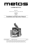
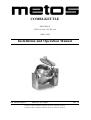
COMBI-KETTLE
PROVENO E
TYPE: 80, 100, 150, 200, 300
CHILL LINE
Installation and Operation Manual
S/N: 10910511010010
Valid from: 01.11.2005
Chill Pro E SCE 4222099, 4222100, 4222101, 4222102, 4222103,
Chill Pro E DCE 4222104, 4222105, 4222118, 4222119, 4222120
Rev.: 1.4
2.11.2005
Rev. 1.4
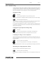
Dear Customer,
Congratulations on deciding to choose a Metos appliance for your kitchen activities. You
made an excellent choice. We will do our best to make you a satisfied Metos customer
like thousands of customers we have around the world.
Please read this manual carefully. You will learn correct, safe and efficient working methods in order to get the best possible benefit from the appliance. The instructions and hints
in this manual will give you a quick and easy start, and you will soon note how nice it is
to use the Metos equipment.
All rights are reserved for technical changes.
You will find the main technical data on the rating plate fixed to the equipment. When you
need service or technical help, please let us know the serial number shown on the rating
plate. This will make it easier to provide you with correct service.
For your convenience, space is provided below for you to record your local Metos service
contact information.
METOS TEAM
Metos service phone number:...............................................................................................
Contact person:....................................................................................................................
2.11.2005
Rev. 1.4
2.11.2005
Rev.
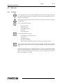
1. General .......................................................................................................... 1
1.1 Symbols used in the manual .......................................................................................... 1
1.2 Symbols used on the appliance ...................................................................................... 1
1.3 Checking the relationship of the appliance and the manual .......................................... 1
2. Safety instructions ........................................................................................ 2
2.1 General ..........................................................................................................................
2.2 Construction of the combi-kettle ...................................................................................
2.3 Safe and correct use .......................................................................................................
2.3.1 Avoiding burns ......................................................................................................
2.3.2 Avoiding risks during mixing and tilting the kettle ...............................................
2.3.3 Other instructions for correct and safe use ............................................................
2.3.4 Changing the settings and adjustments ..................................................................
2.3.5 Safety instructions in the event of malfunction .....................................................
2.4 Disposal of the appliance ...............................................................................................
2.5 Other prohibitions (dangerous methods and procedures) ..............................................
2
3
6
6
6
7
8
8
8
8
3. Functional description .................................................................................. 9
3.1 Intended use of the appliance ........................................................................................ 9
3.1.1 Use for other purposes ........................................................................................... 9
3.2 Construction .................................................................................................................. 9
3.3 Operating principle ........................................................................................................ 9
3.4 Operation switches and indicator lights ...................................................................... 10
3.4.1 Display messages for the user .............................................................................. 12
3.4.2 Error message lights ............................................................................................. 12
4. Operation instructions ............................................................................... 13
4.1 Before use ....................................................................................................................
4.1.1 Preparing the use ..................................................................................................
4.2 Operation procedures ...................................................................................................
4.2.1 Operating the control panel - General ..................................................................
4.2.2 Tilting the kettle ...................................................................................................
4.2.3 Positioning the mixing tool and scrapers ............................................................
4.2.4 Cooking ................................................................................................................
4.2.5 Changing the temperature ....................................................................................
4.2.6 Stopping the cooking ...........................................................................................
4.2.7 Mixing functions .................................................................................................
4.2.8 Water automation ................................................................................................
4.2.9 Timer functions ...................................................................................................
4.2.10 Automatic cooling .............................................................................................
4.2.11 EasyRun programming .....................................................................................
13
13
16
16
16
17
18
19
19
19
21
22
24
25
2.11.2005
4.2.12 Possible power failure during timing or EasyRun program .............................
4.2.13 Self-control (HACCP) (option) ........................................................................
4.3 After use ......................................................................................................................
4.3.1 Cleaning ...............................................................................................................
4.3.2 Periodic service ....................................................................................................
4.3.3 Service recording .................................................................................................
Rev.
26
27
28
28
31
31
5. Installation ................................................................................................... 32
5.1 General ........................................................................................................................
5.1.1 Operating conditions ............................................................................................
5.1.2 Possible interference from the surroundings (to the surroundings) .....................
5.1.3 Storage .................................................................................................................
5.1.4 Unpacking the appliance ......................................................................................
5.1.5 Disposal of the package .......................................................................................
5.2 Installation ...................................................................................................................
5.2.1 Subsurface frame cast into the floor ....................................................................
5.2.2 Surface installation frame fixed to the floor ........................................................
5.2.3 Installing the combi-kettle on the frame ..............................................................
5.3 Electrical connections ..................................................................................................
5.4 Water connections .......................................................................................................
5.4.1 Flo-Ice connections (C4 option) .........................................................................
5.4.2 Water connection and quality requirements .......................................................
5.4.3 Extreme water conditions ....................................................................................
5.5 Ventilation ...................................................................................................................
5.6 Other installations .......................................................................................................
5.7 Procedures after installation ........................................................................................
5.7.1 Adjusting the tilting .............................................................................................
5.7.2 Fastening the mixer motor cover box ..................................................................
5.8 First run and testing .....................................................................................................
5.8.1 Filling the steam generator .................................................................................
5.8.2 Checking the safety block ...................................................................................
5.9 Adjustments, programming .........................................................................................
5.10 Staff training ..............................................................................................................
32
32
32
32
33
33
33
34
35
36
40
43
43
43
44
44
44
44
44
46
46
46
46
47
47
6. Adjustment instructions ............................................................................. 48
6.1 Setting customer specific parameters .......................................................................... 48
6.2 Customer specific parameters, settings and factory presets ....................................... 49
7. Troubleshooting .......................................................................................... 51
8. Technical specifications .............................................................................. 55
2.11.2005
Rev.
2.11.2005
Rev.
2.11.2005
Rev. 1.3
General
1. General
Carefully read the instructions in this manual as they contain important information regarding proper, efficient and safe installation, use and maintenance of the appliance.
Keep this manual in a safe place for eventual use by other operators of the appliance.
The installation of this appliance must be carried out in accordance with the manufacturer’s instructions and following local regulations. The connection of the appliance to the
electric and water supply must be carried out by qualified persons only.
Persons using this appliance should be specifically trained in its operation.
Switch off the appliance in case of failure or malfunction. The periodical function checks
requested in the manual must be carried out according to the instructions. Have the appliance serviced by a technically qualified person authorized by the manufacturer and using
original spare parts.
Not complying with the above may put the safety of the appliance in danger.
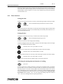
1.1
Symbols used in the manual
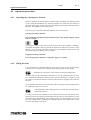
This symbol informs about a situation where a safety risk might be at hand. Given instructions are mandatory in order to prevent injury.
This symbol informs about the right way to perform in order to prevent bad results, appliance damage or hazardous situations.
This symbol informs about recommendations and hints that help to get the best performance out of the appliance.
1.2
Symbols used on the appliance
This symbol on a part informs about electrical terminals behind the part. The removal of
the part must be carried out by qualified persons only.
1.3
Checking the relationship of the appliance and the manual
The rating plate of the appliance indicates the serial number of the appliance. If the manuals are missing, it is possible to order new ones from the manufacturer or the local representative. When ordering new manuals it is essential to quote the serial number shown
on the rating plate.
1
2.11.2005
Rev. 1.3
Safety instructions
2. Safety instructions
2.1 General
The Proveno combi-kettle has been designed and manufactured in compliance with the
Directive regarding Safety of Machinery, the Low Voltage Directive, the Directive regarding Electromagnetic Compatibility and the Directive regarding Pressure Equipment
currently in force.
The Proveno combi-kettle is a pressurized vessel with a maximum operating pressure of
1 bar (or 0,5 bar for certain markets). Overpressure is prevented by means of both mechanical (safety valve, pressure switch) and electronic control.
The Proveno combi-kettle is provided with water level control, which prevents heating if
there is not enough water in the steam generator.
Heating, mixing, water filling or cooling do not function when the kettle is tilted. All functions of the kettle are interrupted when the emergency/stop switch is pressed. The switch
is released by turning it to the right.
The manufacturer does not take responsibility for consequences caused by incorrect use
or use against the operation instructions.
2
2.11.2005
Rev. 1.3
Safety instructions
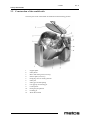
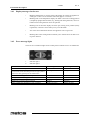
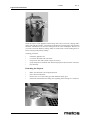
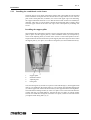
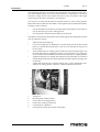
2.2
Construction of the combi-kettle
The main parts of the combi-kettle are illustrated in the following pictures:
1.
2.
3.
4.
5.
6.
7.
8.
9.
10.
11.
12.
Support pillar
Safety block
Mixer and mixing tool (accessory)
Strainer plate (accessory)
Emptying valve for steam generator
Safety lid
Safety grid for fill opening
One-grip tap for cleaning jet
Control panel
Emergency/stop button
Cleaning jet
Water fill to kettle
3
2.11.2005
Safety instructions
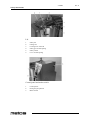
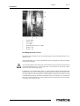
Lid
1.
2.
3.
4.
5.
6.
Safety lid
Lifting arm
Locking lever of the lid
Safety grid for fill opening
Safety switch
Cover for fill opening
Control panel and mains switch
1.
2.
3.
4
Control panel
Emergency/stop button
Mains switch
Rev. 1.3
2.11.2005
Rev. 1.3
Safety instructions
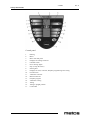
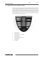
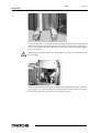
Control panel
1.
2.
3.
4.
5.
6.
7.
8.
9.
10.
11.
12.
13.
14.
15.
16.
17.
Heating
Mixer
Mixer start and pause
Displays for heating and mixer
ON/OFF switch
Error message lights
Stop (to stop the mixer)
Starting time
Displays for timer, water fill, EasyRun programming and cooling
Function time
Automatic water fill
Manual water fill
EasyRun program
Automatic cooling
Tilting
Tilting to upright position
Central dial
5
2.11.2005
Rev. 1.3
Safety instructions
2.3
Safe and correct use
Use of the combi-kettle is prohibited if you have not acquainted yourself with the user
manual and the safety instructions its contains. Observe the following instructions concerning safe and correct use of the appliance. In case of malfunction, proceed as follows:
•
•
•
Check the nature of malfunction to be able to describe it and the situation where it
occurs. Also consult the user manual to make sure that the appliance really functions against the operation instructions.
Review the troubleshooting table contained in this manual to find a possible cause
and repair measures.
Contact your service provider. Be ready to quote the data for easy identification of
the appliance (service code, manufacturing number, model, type, year of purchase
etc.) and to describe the problem as accurately as possible.
Hackman Metos does not take responsibility for any damages in case the operation instructions and warnings contained in this manual are neglected.
2.3.1
Avoiding burns
•
•
•
•
•
•
•
•
2.3.2
Avoiding risks during mixing and tilting the kettle
•
•
•
•
•
•
•
•
6
Beware of the inner surface, the upper rim and the lid that may be hot.
Beware of hot steam when opening the lid.
Beware of the hot mixing tool after cooking. Use protective gloves.
Do not open the bottom valve or the emptying valve of the steam generator when
the kettle is hot (pressurized).
Always make sure that the mixing speed is appropriate, thus preventing foodstuffs
from splashing up through the holes of the lid.
Keep the emptying valve of the steam generator closed. Open it only when there
is no pressure, i.e. when you plan to empty the steam generator entirely or to remove the cooling water.
Beware of hot steam and hot surfaces when you add ingredients to the kettle or
taste the food you are preparing.
When cooling the food, water discharging from the steam generator may be hot at
the beginning of the process.
Stop the mixer before opening the lid either with the
or
button.
Do not push your fingers or utensils into the kettle when the mixer is in operation.
Do not wear scarfs, ties etc. hanging clothing which may catch on the rotating mixer.
Protect your hair to prevent it from catching on the rotating mixer.
Do not touch the rotating mixer.
Operating the mixer when the lid is open is prevented/prohibited under all circumstances (safety regulations at work).
Ensure that nobody stands behind or in front of the kettle during tilting.
Do not stand in front of the kettle when you tilt the kettle or reverse it to a horizontal position.
2.11.2005
Rev. 1.3
Safety instructions
•
•
•
•
When tilting the kettle, make sure there are no objects in the space between the kettle and the pillars or that no objects can fall there when the kettle is being tilted.
When tilting the kettle, make sure that nobody's fingers, hands or other parts of
their body are in danger of getting between the kettle and the pillars.
Always check that the mixing tool has been locked in place before starting to mix.
Always check that the scrapers have been properly attached to the mixing tool.
2.3.3 Other instructions for correct and safe use
•
•
•
•
•
•
Stop the mixer before opening the lid either with the
or
button.
Stopping the mixer by opening the lid activates the emergency/stop function.
Keep the cleaning jet tap closed when the jet is not used.
The mixing tool is easier to position and remove from the kettle when the kettle is
in a tilted position (ergonomics).
Protect yourself in an appropriate way when cleaning the kettle (follow safety and
handling instructions of the detergent).
Do not use the kettle if its protective/cover plates are not properly in place.
Observe the cleaning instructions. Avoid excessive use of water when cleaning the
control pillar. Use of a high-pressure jet is prohibited. Disconnect the control
voltage of the kettle with the ON/OFF switch and with the mains switch before
cleaning the kettle.
1.
2.
ON/OFF switch
Mains switch
•
•
•
Make sure before use that the removable lid is properly in place.
Make sure before use that the safety grid is properly in place.
Always open the lid to its extreme position and check the lid's secure before you
bend down over the kettle.
Check the kettle's safety valve at regular intervals in the way explained in this manual, and keep a record of regular checks.
•
7
2.11.2005
Rev. 1.3
Safety instructions
2.3.4 Changing the settings and adjustments
Only qualified persons with sufficient competence and expert knowledge of the appliance
are allowed to change technical adjustments. The user can adjust some functions of the
appliance to make them better suit their food production (see "Setting customer specific
parameters"). The service parameters can only be adjusted by a qualified person having
the required expert knowledge of the appliance.
2.3.5 Safety instructions in the event of malfunction
In case of a serious emergency, all functions of the appliance must be stopped by pressing
the emergency/stop button or by turning the mains switch to the OFF position. The functions become operable when the button is released by turning it to the right. In case the
reason for using the emergency/stop switch is a serious malfunction jeopardizing safety
at work, contact your Metos service provider immediately.
1.
2.
2.4
Emergency/stop button
Mains switch
Disposal of the appliance
When the appliance has reached the end of its useful life, it must be disposed of in compliance with the local rules and regulations. The best way of dealing with or recycling any
substances which potentially have an adverse impact on the environment is to dispose of
them through a proper waste company.
2.5
Other prohibitions (dangerous methods and procedures)
Deliberate disregard of safety devices is prohibited, as it jeopardizes safe work in the
kitchen. Hackman Metos does not take responsibility for damages caused by deliberate
use of a defective appliance, disregard of the safety precautions by modifying the designed operation of the appliance, or neglect of the technical condition, maintenance or
service of the appliance.
8
2.11.2005
Rev. 1.3
Functional description
3. Functional description
3.1
Intended use of the appliance
The Proveno combi-kettle is designed for professional food preparation. Using Proveno
for other purposes is prohibited. It is forbidden to put corrosive ingredients or substances
reacting with each other in the kettle. Please observe that long-term effect of some substances used in food preparation is corrosive. Such substances are, for example, salt, acetic acid, citric acid and lactic acid.
3.1.1
Use for other purposes
Metos does not take responsibility for functional troubles or damages caused by misuse
or use for other purposes than stated above.
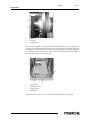
3.2 Construction
The construction of the kettle is of stainless steel throughout (AISI 304). The inner bottom
and jacket are of acid-proof steel (AISI 316). The kettle is triple-jacketed and thermally
insulated throughout.
3.3
Operating principle
The Proveno kettle is heated by steam generated with heating elements. The steam generator and heating elements are located in the lower section of the kettle.
The kettle tilts by means of a tilting motor (40-150-litre kettles). Larger kettles (200-300
litres) are equipped with a hydraulic tilting mechanism. The mixing functions (accessory)
are performed by means of a gear motor. Cooling (accessory) is based on cold water circulating inside the kettle's steam jacket. The control panel of the appliance is situated on
the kettle's right-hand pillar (control pillar).
9
2.11.2005
Rev. 1.3
Functional description
3.4
Operation switches and indicator lights
All Proveno's operation switches, except for the central dial, are push buttons. The buttons
are activated by a light and gentle push or by holding a button down for some time (2-10
seconds), depending on what function you plan to use. Values to be set are selected by
means of an auto-reverse central dial. Turning clockwise (to the right) increases and turning anticlockwise (to the left) decreases the value being selected. If a button is fitted with
an indicator light, it shows if a function is on or if it has been programmed to start later.
The buttons and displays related to various functions as well as the functions of the buttons are illustrated in the following pictures:
1.
2.
3.
4.
5.
6.
7.
8.
9.
10
Heating function
Mixing function
ON/OFF and error message lights
Timer functions
Water fill functions
EasyRun programming function
Cooling function
Tilting function
Central dial
2.11.2005
Rev. 1.3
Functional description
Control panel
1.
2.
3.
4.
5.
6.
7.
8.
9.
10.
11.
12.
13.
14.
15.
16.
17.
Heating
Mixer
Mixer start and pause
Displays for heating and mixer
ON/OFF switch
Error message lights
Stop (to stop the mixer)
Starting time
Displays for timer, water fill, EasyRun programming and cooling
Function time
Automatic water fill
Manual water fill
EasyRun program
Automatic cooling
Tilting
Tilting to upright position
Central dial
11
2.11.2005
Rev. 1.3
Functional description
3.4.1 Display messages for the user
•
•
Blinking number/letter in various fields of the display in general: the appliance is
waiting for a value to be set with the central dial (approx. 3 seconds).
Blinking 'PoS' on the temperature display: the kettle is not in the cooking position
(completely upright and horizontal). E.g. heating and mixing functions, water automation and cooling function cannot be operated.
•
Blinking 'Lid' on the mixer display: the lid is open, mixing is not possible (safety
regulations) or the lid is closed when you try to tilt the kettle.
•
'Err' in the water automation function: the appliance does not get water.
•
Blinking 'SEt' in the cooling function reminds you to start the mixer to make cooling more efficient.
3.4.2 Error message lights
There are two red indicator lights on the control panel to indicate an error or malfunction.
1.
2.
Indicator light 1
Indicator light 2
Error/malfunction
Low water level in steam generator
Defective solenoid switch of the safety grid or the safety grid
is on the kettle and the lid’s lifting arm is in an upper position.
Remove the safety grid and press the STOP button.
Automatic water filling pulses missing
Timing not succeeded (long power failure)
Mixing motor overheated
Malfunction of external cooling equipment
Defect in temperature adjustment (+124°C exceeded)
12
Indicator light 1
illuminates
blinking
Indicator light 2
illuminates
blinking
illuminates
illuminates
illuminates
blinking
blinking (by turns)
blinking
illuminates
blinking (by turns)
2.11.2005
Rev. 1.3
Operation instructions
4. Operation instructions
4.1
4.1.1
Before use
Preparing the use
Daily check before use
•
•
Water supply (hot/cold) is open.
No inappropriate objects in the kettle.
•
Scrapers are correctly attached to the mixing tool. See "Positioning the mixing tool
and scraper".
The mixing tool has been locked in its place: locking part (one end of the handle)
in the groove of the mixer axle, with the handle turned in a horizontal position. Secure fixing by trying to lift the tool out of the kettle by the upper blade.
•
Quarterly check (safety valve)
It is the responsibility of the user to check the safety block of the combi-kettle four times
a year, or have it checked by qualified personnel. The Proveno combi-kettle is equipped
with a four-phase safety block. Testing the block is performed as described below. NOTE:
Values in brackets concern combi-kettle versions with a max. setting temperature of
110°C.
It is not allowed to stand behind the kettle during the safety block check, because, when
the check is completed, the safety valve at the kettle's rear section opens, blowing hot
steam out of the kettle. The test also produces a loud, whistling sound. Use hearing protectors. The kettle must always be clean and empty.
•
•
•
•
•
•
Switch the kettle on, set the temperature to a max. value of 120°C (110°C) and wait
until the kettle heats up to the set value and the heating stops (phase 1 tested).
Stop the heating function by pressing
until 'On' appears on the display.
Press the
and
buttons simultaneously and hold them down
throughout the test.
On the temperature display, 'tESt' blinks three times, the heating is switched on
again and the temperature display is updated according to the temperature rise.
When the temperature of 124°C (114°C) has been reached, the heating is interrupted for 3 seconds and 'OFF' appears on the temperature display.
After a lag of 3 seconds, the heating is switched on again and the temperature display continues to show temperature. However, letter 'a' is displayed instead of letter 'c' (phase 2 tested).
13
2.11.2005
Rev. 1.3
Operation instructions
•
•
Also the pressure switch starts to function at 124°C (114°C) and informs about
correct functioning by alternately blinking the red indicator lights inside the triangles (phase 3 tested).
After the pressure switch function has been checked, the heating is forced further
until the safety valve opens. The temperature display shows then about 128°C
(116°C) and the pressure gauge correspondingly 1,5 bar (0,75 bar) (phase 4 tested).
In case the safety valve does not open when the pressure gauge indicates 2 bar, the buttons must be immediately released and the combi-kettle’s mains switch turned to the
OFF position. Using the kettle is strictly forbidden. Contact qualified service personnel
without delay to repair the fault.
•
•
Complete the check by releasing the buttons.
Information on the completed safety block check is automatically recorded in the
combi-kettle's memory for potential retrieval later on. For the user's self-control,
safety block checks and other procedures carried out to maintain the appliance in
working order should be recorded in the 'Maintenance information' table below.
In case all phases of the test could not be carried out according to the above description,
the use of the kettle is absolutely forbidden. Contact immediately an authorized service
company to repair the fault.
14
2.11.2005
Rev. 1.3
Operation instructions
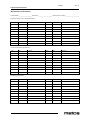
Maintenance information
Combi-kettle _________________ Serial No. __________________ Taken into use (date) __________________
Quarterly safety valve check performed
Date
By
Remarks
Date
By
Remarks
Remarks
Date
By
Remarks
Remarks
Date
By
Remarks
Yearly maintenance performed
Date
By
Descaling performed
Date
By
15
2.11.2005
Rev. 1.3
Operation instructions
4.2 Operation procedures
4.2.1
Operating the control panel - General
When the appliance is started with the ON/OFF switch, all displays and indicator lights
on the control panel illuminate for a short time (display test). After that, 'On' remains on
the temperature display and the time on the timer display (if the kettle is fitted with a timer
function). The appliance is now ready for use.
The same logic is repeated in all button functions of the control panel.
Selecting/activating a function:
Press briefly the appropriate button and then set the value desired using the central
dial, for example:
The appliance waits for the value for three seconds (the selected display is blinking),
whereafter the appliance starts to perform the function according the set value. In some
functions, e.g. in automatic water fill, a second press is still needed to confirm and activate
the function before the function starts to operate.
Stopping/cancelling a function:
Press the appropriate button for a long time (approx. 2 seconds).
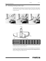
4.2.2 Tilting the kettle
It is not possible to tilt the kettle when the lid is closed. In case you try to tilt the kettle
with the lid in a closed position, a blinking 'Lid' message appears on the display.
Tilting the Proveno kettle is carried out by pressing the tilting button.
The kettle tilts as long as the button is held down. In case the "pull-back" function is on,
(see "Adjustment instructions, Setting customer specific parameters"), a slight reversing
movement occurs after the button is released, which decreases dripping of food from the
the spout.
In case the kettle is tilted to its extreme position, the reversing movement making the kettle completely empty does not occur.
Tilting the kettle to the cooking position is carried out by pressing the upright position button.
For safety reasons (safety regulations), the reversing movement lasts only as long as the
button is pressed. The upright position button must be pressed so long that the reversing
movement stops and the kettle is in the cooking position. In case the kettle is not reversed
up to the cooking position, a blinking 'PoS' message appears on the display when you try
to switch the heating or mixing on.
16
2.11.2005
Rev. 1.3
Operation instructions
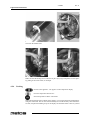
4.2.3
Positioning the mixing tool and scrapers
Attach the scrapers by placing the pins on the mixing tool into the holes on the scrapers.
After that turn the scraper into place by lifting the scraper’s lower part. Finally pull the
scraper forward. The bevel (1) will on the lower scraper point upwards and on the side
scraper downwards.
The mixing tool is equipped with 1-4 scrapers, depending on the size of the tool.
Scraper
Scraper A2
Scraper B2 (bottom)
Scraper C2 (bottom)
40
1
60
1
1
80
1
-
100
2
1
-
150
1
1
1
200
2
1
1
300
1
1
2
Scrapers are not needed when preparing large quantities of mashed potatoes or when
kneading dough. Use scrapers in all other cooking modes to increase the efficiency of heat
transfer and to help the cleaning of the kettle.
It is easiest to attach the mixing tool to the mixer axle when the kettle is in a tilted position.
Push the ring on the mixing tool into the kettle's mixer axle and fit the mixing tool in place,
while the lifting handle is straight so that the locking device of the lifting handle sets in
the groove at the upper end of the mixer axle.
17
2.11.2005
Rev. 1.3
Operation instructions
Then turn the handle aside.
Make sure that the mixing tool is locked in its place by trying to lift/pull it out of its place
by pulling at the mixer blade, for example.
4.2.4 Cooking
Switch on the appliance. 'On' appears on the temperature display.
Press the temperature button once.
Select temperature with the central dial.
When the temperature starts to blink on the display, you can select the desired temperature
using the central dial. The set value is automatically saved in the memory after about three
seconds, temperature blinking stops on the display and the kettle starts to heat. If you did
18
2.11.2005
Rev. 1.3
Operation instructions
not manage to set the temperature while the temperature display was blinking, press the
temperature button again and select the desired temperature with the central dial.
Temperature setting and temperatures displayed:
0 - 50°C
51 - 100°C
101 - 120°C
kettle inner surface temperature on the display
food temperature on the display
steam jacket temperature on the display
Heating is only switched on when the kettle is in an upright position (cooking position).
If the heating function is selected when the kettle is not in an upright position, the message
'PoS' appears on the display indicating that the heating will not switch on because the kettle is not in the cooking position. Open the lid and revert the kettle to the cooking position.
4.2.5
Changing the temperature
Press the temperature button.
Select the temperature desired.
4.2.6 Stopping the cooking
Press the temperature button for a long time (approx. 2 seconds).
The heating goes off when 'On' appears on the display.
4.2.7
Mixing functions
Starting the mixer (manual mixing)
Switch on the appliance. The temperature display indicates 'On'.
Select the mixing function. Message '15' appears on the mixer display.
Start the mixer.
You can adjust the mixing speed with the central dial while the mixer display is blinking.
Changing the speed
When the mixer is running, press the start/pause button once.
Select the speed (15-140 rev./min.) with the central dial.
NOTE: You cannot change the mixing speed, if a mixing program (P1-P6) is in operation.
However, it is also possible to start power mixing when a mixing programs is running (see
"Power mixing during mixing").
19
2.11.2005
Rev. 1.3
Operation instructions
Auto-reverse function
When the mixer is running, press the mixer button once. A rotating symbol
appears on the left-hand side of the display and the mixer is auto-reversing.
Power mixing during mixing
When the mixer is running, press and keep pressed the mixer button. A rotating symbol appears on the whole display.
Power mixing is heavy auto-reverse mixing, which continues as long as the button is held
down. Power mixing can be used whenever the mixer is running, also during the pre-set
mixing programs.
Make sure before using power mixing that possible splashes of food do not cause any danger to safety at work.
Pre-set mixing programs (P1 - P6)
Select the mixing function. Message '15' appears on the mixing display
Select the desired mixing program P1 - P6.
Start the mixing program.
The display shows the number and phase of the program in operation (e.g. P2.2). The preset programs are as follows:
P1
P2
P3
P4
P5
P6
Gentle stirring with pause, soups
- total time: continuous, max. 5 hours
Meat cooking, powerful auto-reverse mixing
- total time: 44 min., whereof 6 min. crumbling
Mashed potatoes, powerful auto-reverse mixing
- total time: 13 min. whereof 6 min. mashing
Desserts
- total time: 1 hour 20 min., whereof last 40 min. whipping
Porridges
- total time: 1 hour 40 min.
Doughs
- total time: 6 min.
Interrupting/continuing the mixer program
Press the start/pause button once.
The mixer stops according to the instructions also when the lid is opened. The correct way
to stop the mixer is to press the stop or start/pause button:
Opening the lid activates the emergency/stop function.
20
2.11.2005
Rev. 1.3
Operation instructions
Stopping the mixer program
Press the stop button once.
The mixer stops according to the instructions also if the lid is opened. The correct way to
stop the mixer is to press the stop or start/pause button:
Opening the lid activates the emergency/stop function.
4.2.8 Water automation
Manual water fill
Press and keep pressed.
Cold water flows into the kettle as long as the button is held down. The display shows all
the time the amount of water in litres. The display goes off and sets to zero soon after the
water fill is completed.
In case water supply to the appliance is prevented, the display shows an error message
'Err'. Check that the water supply closing valve is open.
Automatic water fill
Press once.
Select the amount to be filled.
Start filling by pressing once again.
The selected amount of cold water flows automatically into the kettle. The display shows
all the time the amount in litres poured into the kettle.
Stopping/cancelling the automatic water fill
Interrupt water fill by pressing once.
Water flow will immediately stop. The amount of water filled is shown on the display for
10 seconds. The display goes off to indicate that the function has been cancelled/stopped.
Changing the amount of automatic water fill during filling
Interrupt the function by pressing once. The display shows the selected
amount in litres.
Select the new amount to be filled within 10 seconds. You can select the
amount to be filled between the filled amount and the kettle's net volume.
Continue filling by pressing once.
21
2.11.2005
Rev. 1.3
Operation instructions
When the automatic water fill is completed, the filled amount is shown on the display for
10 seconds, after which the display goes off. The filled amount is saved in the memory
until the kettle's control voltage is cut, and it can be displayed by pressing the automatic
water fill button once.
4.2.9 Timer functions
Setting the time
Setting correct time by the clock is necessary to make timing and data collection possible.
Press and simultaneously hold down for about 2 seconds.
Set the time.
Start selecting the time within three seconds after the timer display begins to blink. When
you have set the time, it will be saved automatically in the memory after about three seconds, and the timer starts up.
Setting the date
Setting the correct date is necessary to make the data collection possible.
Press and simultaneously keep pressed.
In about 2 seconds, the timer display starts blinking.
Continue holding the button down until 'Yr' blinks on the timer display and two last digits
of the year illuminate. Release the buttons.
If needed, select a new year within 3 seconds.
After the year is locked, 'Mo' and a month begin to blink on the timer display.
If needed, select a new month within 3 seconds.
After the month is locked, 'dY' and a day of the week begins to blink on the timer display.
If needed, select a new day within 3 seconds.
After the day is locked, the timer display begins to show the actual time.
Activating the starting time and duration of cooking
Press once.
Proveno suggests the cooking temperature, starting time and duration that you used the
previous time. If you do not want to change the values, the functions are activated automatically in about 15 seconds. Cooking begins at the selected time and Proveno cooks at
the set temperature for the set period of time. Counting the cooking time does not begin
until the set temperature has been reached. Proveno is equipped with an automatic holding function (factory setting +70°C). You can change the holding temperature between
+50 - +100°C (see "Setting customer specific parameters").
22
2.11.2005
Rev. 1.3
Operation instructions
After the cooking time has elapsed, ‘HoLd’ appears on the display, in case the cooking
temperature is higher than the set holding temperature. Otherwise Proveno holds the food
at the set cooking temperature also after cooking.
In case the starting time and operation time were saved in the memory before you managed to set the times desired, first cancel the timer functions by pressing the start or function buttons for about two seconds. The indicator lights of the buttons go off. After that,
start activating the time functions from the beginning.
Changing the temperature of timer-set cooking
Press once and select.
Changing the timer-set starting time
Press once and select.
Changing the timer-set cooking time
Press once and select.
Deactivating the activated/programmed timer
Press and keep pressed for about 2 seconds.
Deactivating the activated/programmed operation time
Press and keep pressed for about 2 seconds.
In case the starting time has not yet been reached, the starting time has to be deactivated
by pressing the starting time button for about two seconds.
Activating the "egg timer" function and changing the operation time
Press once and select.
•
•
•
•
In case none of the Proveno combi-kettle functions is activated, the clock functions
as an entirely separate clock, and the buzzer sounds after the set time.
In case the heating is on, it continues for the set time. After that, the buzzer sounds
and the combi-kettle sets to automatic holding (see "Activating the starting and
cooking time").
In case the mixer function is on, the Proveno combi-kettle mixes for the set time,
after which the buzzer sounds and the mixer stops.
In case both heating and mixing functions are on, both functions continue for the
set time with the set values, after which the buzzer sounds and the mixer stops. The
heating remains at the set value (if lower than the holding temperature) or keeps
the automatic holding temperature ('HoLd' on the display).
Stopping the "egg timer" function
Press and keep pressed for about 2 seconds.
23
2.11.2005
Rev. 1.3
Operation instructions
4.2.10 Automatic cooling
Cooling is based on cold tap water circulating in the kettle's steam jacket. Mixing and use
of scrapers make the cooling more efficient. The cooling time depends, for example, on
the product and the amount to be cooled, the product's initial and end temperature, the
flow rate and temperature of the cooling water, as well as mixing operations.
Starting the cooling
Press once.
Select the target temperature for the product being cooled.
Wait three seconds until 'no' is displayed. With the central dial, select 'YeS' on the display.
Start the cooling by pressing once.
‘Set’ is blinking on the display to remind you that mixing makes the cooling much more
effective. Choose a mixing operation suitable for the product and the load.
If 'no' remains on the display for 10 seconds, i.e. the 'YeS' selection is not made, the cooling function is cancelled. If you, however, want to start cooling, activate the function by
starting from the beginning.
Changing the target temperature during cooling
Press once.
Select a new target temperature (on the display: food temperature).
Cooling continues automatically until the new temperature has been reached.
Continuing the cooling to a lower temperature
When food temperature reaches the temperature set, the flow of cooling water stops, ‘rdy’
blinks on the display and the buzzes sounds. The mixer continues rotating if this function
has been selected.
Press once (buzzer stops sounding).
Select a new target temperature (on the display: food temperature).
The new target temperature is reached, 'rdy' is again blinking on the display and the buzzer
sounds.
Maintaining the cooling temperature (‘Hold’)
The Proveno kettle can maintain the temperature reached.
Press once (buzzer stops sounding).
Food temperature is blinking on the display, but now a new temperature selection is not
made.
24
2.11.2005
Rev. 1.3
Operation instructions
The ‘Hold’ function is automatically activated and the kettle starts to maintain the reached
temperature, i.e. cooling continues when food temperature rises, but the buzzer does not
sound.
Stopping the cooling
Press and keep pressed for about 2 seconds.
When the cooling is stopped, the kettle starts immediately automatic water emptying from
the kettle's steam jacket. The display continuously shows the emptying time for the remaining water. During emptying, all the kettle functions, except for tilting, are locked.
You cannot cancel the stopping of cooling; the emptying time must be allowed to come
to an end.
If the kettle is tilted or the power is cut before the emptying time has expired, emptying
will be interrupted and it continues, when the kettle is reverted to an upright position or
the power is connected. After the emptying time, the kettle is ready for cooking ('On' is
displayed).
4.2.11
EasyRun programming
The following functions are possible when a set program is in operation:
power mixing
interrupting the mixing function
stopping the mixing function
stopping with the emergency/stop button.
If you want to collect temperature information (self-control, HACCP), the program in
question has to be activated before programming (see “Self-control (HACCP), Activating
the collection of self-control data")
The programmed function is performed at the set time during the same day or the following day. This means that you cannot set a program to start, for instance, on the following
Monday.
The mixing program of the EasyRun program is a stirring program that cannot be
changed.
Activating the program
Press once.
Select the values you want by first pressing the button of the appropriate function and by
setting the value desired with the central dial:
Activate the programming by pressing again.
25
2.11.2005
Rev. 1.3
Operation instructions
The previously set values are available in the Proveno memory. On the clock display, the
starting time and operation time (with letter r in front) alternate. When the program has
been activated, all displays show the set values and the indicator light of the PROG button
illuminates.
Cancelling the programming
Press and keep pressed for about 2 seconds.
The indicator light of the PROG button goes off and 'On' is displayed.
You can cancel the program before it starts in the way described above. If the program has
already started, you can cancel/deactivate the program in the same way, whereby the timer
is deactivated, but the mixer and heating functions continue. If desired, you can stop the
mixer with the STOP button. You can cut the heating by pressing the temperature button
for about 2 seconds, until the temperature display shows 'On'.
Changing the program setting values before starting the program (=
new programming)
First cancel the active programming by pressing for about 2 seconds.
Select the desired setting values by first pressing the button of the appropriate program
and by setting the desired value with the central dial:
Activate a new program by pressing once.
When programming has been activated, the set values are shown on all displays and the
PROG button indicator light illuminates.
4.2.12 Possible power failure during timing or EasyRun program
A message appears on the timer display indicating power failure during timing or during
the starting or operation time of the EasyRun program.
Power failure during the starting time
In case of power failure during the starting time, the kettle's timer display shows, when
the power supply is restored, how much the start was delayed:
•
•
during operation time, letter E + delayed time in hours and minutes and the remaining operation time alternate on the display, e.g. E1.10 / r0.58
after operation time, the display shows letter E + delayed time in hours and minutes, e.g. E1.10
Power failure during the operation time
In case of power failure during the operation time, the kettle's timer display shows, when
the power supply is restored, for how long a time the operation was interrupted:
26
2.11.2005
Rev. 1.3
Operation instructions
•
•
•
during operation time, letter E + interrupted time in hours and minutes and the remaining operation time alternate on the display, e.g. E0.12 / r0.46, and the green
indicator light on the operation time button is blinking
after operation time, the display shows letter E + interrupted time in hours and minutes, e.g. E1.12, and the green indicator light on the operation time button is blinking
in case of several power failures, their durations are summed up
Power failure during both the starting time and operation time
In case of power failure during both the starting time and operation time, the kettle's timer
display shows, when the power supply is restored, the total time the timing was delayed:
•
•
•
4.2.13
during operation time, letter E + total delayed time in hours and minutes and the
remaining operation time alternate on the display, e.g. E1.22 / r0.27, and the green
indicator light on the operation time button is blinking
after operation time, the display shows letter E + total delayed time in hours and
minutes, e.g. E1.22, and the green indicator light on the operation time button is
blinking
in case of several power failures, their durations are summed up
Self-control (HACCP) (option)
A separate instruction manual is available on the HACCP program related to the Proveno
combi-kettle’s self-control. The self-control function is an option on models M, C1 and
C2. If a message 'InF1' appears on the display, the self-control function cannot be
switched on or it has been intentionally switched off by the user. If your Proveno kettle is
fitted with the self-control program, which you want to take into use, you have to change
parameters according to "Adjustment instructions, Setting customer specific parameters"
later in this manual. The parameter for self-control is No. 50.
Activating the collection of self-control data (HACCP)
Press and simultaneously keep pressed until 'HACC On' blinks on the display.
The text blinks three times, after which a dot at the lower right-hand edge of the temperature display keeps on blinking to indicate data collection.
Stopping the collection of self-control data
Press and keep pressed for about 5 seconds.
'HACC OFF' blinks three times on the display. The collection of temperature data is interrupted and the blinking dot on the temperature display goes off.
27
2.11.2005
Rev. 1.3
Operation instructions
4.3
After use
4.3.1 Cleaning
Use of a high-pressure hose is forbidden. High-pressure hoses generate huge amounts of
water fog that might contribute to contamination of food and food handling surfaces over
large areas in the kitchen.
Switch off the appliance with the ON/OFF switch or the mains switch before starting to
wash the kettle.
Tools not allowed for cleaning:
•
•
•
•
•
high-pressure hose
all metallic tools
rough rubbing sponges
steel wool
abrasive detergents
Tools recommended for cleaning:
•
•
•
•
•
special detergents for stainless steel
nylon brush
soft rubbing sponges
non-abrasive steel wool
other materials intended for stainless steel that do not scratch the surface
All accessories, such as strainer plates and its parts, mixing tools and scrapers, cooking
baskets and parts of the safety lid can be washed in a dishwasher suitable for washing such
items.
The less the kettle surface gets scratched, the easier it is to clean. The fastest and easiest
method is to clean the kettle every time right after use. Always use a top tray on the control
pillar. This will keep the pillar clean. Do not spray water on the control panel. Clean the
pillars of the appliance by wiping.
28
2.11.2005
Rev. 1.3
Operation instructions
Wash the exterior of the appliance with running water only if necessary. Wiping with a
damp cloth will often suffice. Consider the requirements of food hygiene when cleaning
the kettle. Abundant use of water for soaking increases water consumption. However, if
you want to clean the kettle by soaking, make use of the mixer to make soaking more efficient, mixing slowly during soaking.
Cleaning procedures:
•
•
•
•
•
Switch the appliance off.
Cool down the kettle with cold water.
Scrape loose dirt with a plastic scraper (accessory)
Spray detergent into the kettle, then brush and spray the kettle with water until clean.
Dry the kettle.
Detaching the lid parts
•
•
•
•
Make sure the kettle is in an upright position.
Place the lid on the kettle.
Remove the cover of the safety grid and detach the safety grid.
Detach the solid lid from the lifting arm by pulling at the locking lever of the lid.
29
2.11.2005
Rev. 1.3
Operation instructions
Refitting the lid parts
Place the solid lid on the kettle approximately in the correct position.
Pull the lifting arm down over the lid. Turn the solid lid so that the guiding pin lines up
with the groove of the lifting arm.
1.
2.
3.
4.
5.
6.
Solid lid
Lifting arm
Guiding pin
Locking lever of the lid
Safety grid for lid opening
Cover for fill opening
Press the lid arm against the lid so that the fixing cone is guided into the fixing part and
the locking lever snaps in the locked position. Make sure that the lid is locked on the arm.
Put the safety grid and its cover in place.
30
2.11.2005
Rev. 1.3
Operation instructions
4.3.2
Periodic service
Like a car, a food preparation appliance should be kept in good working order with the
help of preventive maintenance. This guarantees trouble-free and safe operation of the appliance. Depending on how much the kettle is used and in what kind of conditions it is
operated, the technical condition of the Proveno combi-kettle should be checked according to plan from time to time. For example, the amount of scale built up on the steam system depends on the use of the kettle and the hardness of local water. Contact the Metos
service for recommendations on preventative maintenance service to be performed. No
parts of the Proveno kettle have been specified to generally need periodic service.
4.3.3 Service recording
Keep a record of all service and repair measures carried out for the Proveno combi-kettle
during its life cycle. Service history may speed up future service measures, help in controlling the costs and in planning new investments. The safety valve must be periodically
checked as instructed in this manual. Enter the check data in the "Maintenance information" table contained in this manual.
31
2.11.2005
Rev. 1.3
Installation
5. Installation
5.1 General
Please observe the instructions given in this chapter concerning the installation and adjustments that must be done before taking the Proveno combi-kettle into use. Strict observance of the instructions prevents malfunctions and damages potentially caused by
defective installation.
Do not switch the power on if the installation place is damp or wet (building site conditions).
5.1.1 Operating conditions
The Proveno combi-kettle can be used in a normal, air-conditioned professional kitchen.
The room temperature of the installation place must not exceed +40°C and the relative humidity must be less than 80% (condensation on surfaces not allowed to occur). If the temperature of the facility in winter conditions is below 0°C, the steam generator of the
combi-kettle must be drained and the kettle must be emptied to avoid damage caused by
freezing. The kettle's pipes and solenoid valve bodies must be emptied at the same time.
5.1.2 Possible interference from the surroundings (to the surroundings)
The Proveno combi-kettle fulfils the requirements of the EMC directive concerning the
emissions and immunity to electromagnetic disturbances. In case there are electronically
controlled appliances and, in particular, devices fitted with a frequency converter in the
installation place, it is recommended to ensure their conformity with the relevant regulations and that their cabling has been done according to instructions.
5.1.3
Storage
The Proveno combi-kettle must be stored in a dry place, at a temperature between +10 and
+40°C. The kettle should be kept in its transport package during storage.
If the appliance is stored in construction site conditions, special care must be taken not to
damage it through other operations on the site.
•
•
32
Protect the exterior of the combi-kettle from scratches and knocks.
Protect the combi-kettle from construction site dust.
2.11.2005
Rev. 1.3
Installation
•
5.1.4
Protect the combi-kettle from sparks produced by welding, grinding and abrasive
cutting wheels. These can later cause rust spots on the stainless steel surface of the
appliance.
Unpacking the appliance
The combi-kettle should be transported in its own package as close as possible to the installation place before final unpacking. Do not remove the protective foils until after installation, just before the first use of the kettle.
After removing from the transport pallet, the combi-kettle is not stable until it has been
bolted down to the installation frame. It is strictly forbidden to operate or tilt the kettle
before it has been fixed to the floor according to the installation instructions. When the
combi-kettle is removed from its transport pallet, it must be supported to prevent it from
falling before it is fixed to the floor. If the kettle falls down, this may cause injury to people or damage to property.
5.1.5
Disposal of the package
In connection with unpacking, all packing material must be sorted and disposed of in accordance with local recycling regulations.
5.2 Installation
Check before installation from the installation drawing that there is enough space behind
the kettle for tilting and servicing. Also check the location of the floor drain.
The Proveno combi-kettle is designed for installation in a place with a floor drain in front
of the kettle. The arrangement with a pouring channel and floor drain behind the kettle is
not suitable for use with the combi-kettle
The combi-kettle can be installed in two different ways:
•
•
On a subsurface installation frame, the frame cast into the floor
On a surface installation frame, the frame fixed to the floor surface
Fixing the kettle directly to the floor without frames is forbidden.
Either subsurface frames or surface frames must be in position before the installation of
the combi-kettle is started.
33
2.11.2005
Rev. 1.3
Installation
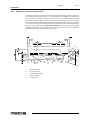
5.2.1 Subsurface frame cast into the floor
Installation frames are mounted according to the installation drawing, with the help of distance guides supplied with the delivery. The frames must be installed in a horizontal position and fixed so that they do not move during casting. The installation frames must be
positioned so that their upper surface is 30 mm above the finished floor surface. The junction of the installation frame and floor is filled with flooring material or silicone mastic.
To achieve the best result regarding tightness, the installation frame should be filled up to
the top level e.g. with acrylic filler after the installation. The main points concerning the
installation of the subsurface frame are shown in the picture below. For more detailed installation instructions, see the installation drawings.
4
3
5
1
2
1.
2.
3.
4.
5.
34
Installation frame
Concrete casting
Finished floor surface
Silicone mastic
Acrylic filler
2.11.2005
Rev. 1.3
Installation
5.2.2
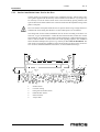
Surface installation frame fixed to the floor
Surface frames are mounted according to the installation drawing, with the help of distance guides supplied with the delivery. If the inclination of the floor is very steep, it may
be necessary to level the surface frame closer to the horizontal by placing stainless steel
spacers between the frame and the floor. This will ensure that the adjustment range of the
pillars is adequate.
Pieces of stainless steel plate should be used as spacers that are large enough and have a
suitable hole for the fixing bolt. Washers or other small spacers are not allowed.
The fixing bolts for the surface installation must be chosen according to the floor construction. A type recommended is a UKA M10x150 chemical bolt, which suits various
floor materials. The junction of the surface frame and the floor is filled with flooring material or silicone mastic. To achieve the best result regarding tightness, the installation
frame should be filled up to the top level e.g. with acrylic filler after the installation. The
main points concerning the installation of the surface frame are shown in the picture below. For more detailed installation instructions, see the installation drawings.
1
4
5
6
3
2
1.
2.
3.
4.
5.
6.
Surface frame
Concrete casting
Fixing bolt for surface frame
Finished floor surface
Silicone mastic
Acrylic filler
35
2.11.2005
Rev. 1.3
Installation
5.2.3 Installing the combi-kettle on the frame
The front and rear cover plates of the kettle's support and control pillar must be detached
before installation. Each plate has been fixed at its lower edge with two screws. The rear
plate of the control pillar has, in addition, two screws at the upper edge. After detaching,
the support chain holds the front cover so that the ribbon cable would not accidentally be
damaged. After that, it is also possible to detach the lead-through plate of supply cables
and water pipes located at the lower rear edge of the control panel by loosening four
screws.
Installing the support pillar
Start installing the combi-kettle or kettle group by first positioning the left-hand support
pillar in place. Lift the support pillar (1) on the installation frame (2) and adjust it by
means of the adjusting bolts (3) located on the corners to a horizontal position and to a
height of 900 mm measured from the top of the support pillar front edge to the floor. When
the support pillar (1) is in place, fix it with two fixing bolts (4) to the installation frame (2).
1.
2.
3.
4.
Support pillar
Installation frame
Adjusting bolt
Fixing bolt
Next, the bearing unit (2) and the cover plate for axle lead-through (3), both supplied with
delivery, are installed on the support frame (1). First position the assembled bearing unit
(2) on three upper bolts. Fix the washer and nut (5) to the uppermost bolt to hand tightness.
Then install the mounting bracket (4) of the cover plate on two lower bolts and fasten the
washers and nuts (5) to hand tightness. After that fix the cover plate (3) with the washer
and nut. Check that the bearing unit (2) and the cover plate (3) hole are concentric before
you tighten all the fixing bolts (5) (6).
36
2.11.2005
Rev. 1.3
Installation
1.
2.
3.
4.
5.
6.
Support pillar
Bearing unit
Cover plate
Mounting bracket for cover plate
Washer + nut
Washer + nut
Installing the kettle section
The kettle can be transferred from its transport pallet onto the installation frame in two
different ways.
The first alternative is to cut the longitudinal boards of the pallet and push the fork-lift
trolley below the kettle.
Care must be taken that the lifting arms of the fork-lift trolley do not hit the parts protruding from the kettle bottom, i.e. the mixing motor cover box (Proveno 40, 60, 80, 100) as
well as the drain and discharge pipes.
Furthermore, it is recommended to place e.g. plywood strips between the fork-lift trolley
and the kettle bottom. Before lifting, the transport support of the kettle's left-hand axle and
the support pillar are detached from the transport pallet. It should be observed that, owing
to the ball-shaped bearing, the kettle control pillar also moves sideways. It is advisable to
put a piece of foamed plastic or a rolled cellular board between the kettle and control pillar
so that they do not hit each other.
37
2.11.2005
Rev. 1.3
Installation
The second alternative is to transfer the kettle by lifting the kettle section by its left-hand
axle and by a lifting bar pushed through the control pillar. The lifting bar is positioned below the cross supports, located at the front and rear edge of the control pillar, slightly
above the bearings.
When pushing the support through the control pillar, be careful not to damage the cables
and water pipes.
Before the left-hand axle of the kettle is pushed into the support pillar bearing, remember
to put a gasket (1) on the axle. Make sure that the shoulder of the axle lines up with the
bearing and lock the axle with a lock ring (2) and fixing bolts (3).
38
2.11.2005
Rev. 1.3
Installation
1.
2.
3.
Gasket
Lock ring
Locking screw
Next, the control pillar (1) is adjusted by means of the adjusting bolts (3), located on the
corners, to a horizontal position and on the same level with the support pillar. When the
control pillar (1) is in position, it is fixed to the installation frame (2) with four fixing bolts
(4). Check that the space between the kettle section and the support and control pillars is
the same, both at the top and at the bottom.
1.
2.
3.
4.
Control pillar
Installation frame
Adjusting bolt
Fixing bolt
In this phase the front and rear cover plates of the support pillar can be refitted.
39
2.11.2005
Rev. 1.3
Installation
Installing the following kettle section
If a kettle group is being installed, proceed as follows:
Before installing the next kettle section, remove the bearing cover plate of the kettle already installed. After this, install the bearing unit and the axle lead-through cover plate,
supplied with the kettle delivery, exactly in the same way as it was installed on the support
pillar.
The installation of the next kettle section on the control pillar of the previous kettle takes
place in the same way as the installation of the first kettle on the support pillar.
5.3 Electrical connections
The electrical connections of the Proveno combi-kettle can only be carried out by a qualified electrician having the necessary competence for the installation and service of electrical appliances.
The support pillar cover plate, including the water tap, is a fixed component, not intended
for detaching. Do not force it upwards when removing the upper side plate.
To make the electrical connections, the upper left-hand side plate, where the mains switch
is located, must be removed and the cover of the electrical box underneath must be
opened.
1.
2.
3.
4.
5.
Front plate
Mains switch
Upper rear plate
Upper side plate
Screw
Turn the mains switch (2) to the OFF position.
40
2.11.2005
Rev. 1.3
Installation
If the control pillar front plate (1) is in place, it must be first detached by opening two
screws (5) at the lower section of the plate.
Detach the upper rear plate (3) by opening the two screws (5). The cable of the lid switch
hinders the plate being detached entirely, but you can move the plate a little aside.
4. Upper side plate
5. Screw
Loosen the screws (5) located on the upper and lower corners of the upper side plates (4).
Turn the lower part of the upper side plate (4) cautiously outwards and after that straight
downwards.
1.
2.
3.
Cover
Screw
Shaft
Open the screws (2) on the electrical box cover (1) and remove the cover. Be careful that
the mains switch shaft (3) does not get loose from the switch.
41
2.11.2005
Rev. 1.3
Installation
1.
2.
3.
4.
5.
6.
Supply cable
Lead-through plate
Cable bushing
Mains switch
N and PE cables
Cover plate
Detach the cover plate (6) of the mains switch by pulling. Slip the supply cable (1) through
the cable bushing (3) of the lead-through plate (2) (possibly detached) and upwards via
the lead-through of the electrical box further to the mains switch (4), and connect the
phase wires of the cable to the switch and N and PE cables (5) to the terminal blocks.
After that, check phase order to make sure that the mixer and tilting motors rotate in the
correct direction.
Close the lid and safety grid of the combi-kettle, but do not put the cover of the safety grid on.
Turn the mains switch to position I and switch the combi-kettle on with the
ON/OFF switch.
Start the mixer by first pressing the mixing function button and after that the mixer start button.
The mixer should rotate clockwise.
Stop the mixer by pressing the red STOP button.
On hydraulically tilted Proveno 200 and 300 combi-kettles, you still have to check the rotation direction of the hydraulic pump motor.
Open the kettle lid and tilt the kettle by pressing the tilting button.
The correct rotation direction is anticlockwise viewed from the motor's cooling fan end.
An arrow indicating the rotation direction is fixed to the motor on the same side where the
connection box is located.
42
2.11.2005
Rev. 1.3
Installation
If the rotation direction in two foregoing points is wrong, two phases of the supply cable
coming to the mains switch have to be exchanged.
Tighten the screws of the cable connections and the cable bushing properly, press the cover plate of the mains switch in place, refit the electrical box cover, the upper rear plate and
the upper side plate.
5.4
Water connections
Water connections of the Proveno combi-kettle can only be carried out by a person with
professional competence in the installation and service of heating, plumbing and air conditioning equipment.
The location of the water connection points appears from the installation drawing. Both
cold and hot water connections must be fitted with a closing valve and a non-return valve
(not included in delivery). The sizes of water connection points are as follows:
Cold water: connection with R1/2" inner thread, supply with min. 15 mm inlet pipe
Hot water: Cu pipe, outer dimension 10 mm, supply with 10 mm inlet pipe (max. +60°C)
If the cold water inlet pipe is smaller than 15 mm, water flow will decrease and the filling
times will be longer than indicated.
5.4.1
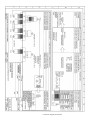
Flo-Ice connections (C4 option)
The location of Flo-Ice connection points appears from the installation drawing. The connections must be fitted with a shut-off valve (not included in delivery).
Connection
Thread
Model
Flo-Ice IN to mixer
Flo-Ice OUT from mixer
Flo-Ice IN to jacket
Flo-Ice OUT from jacket
Pressurized air IN to jacket
Air vent OUT
R1/2” external thread
R1/2” external thread
R1/2” inner thread
R3/4” inner thread
R1/2” inner thread
R1/2” inner thread
DCE
DCE
SCE, DCE
SCE, DCE
SCE, DCE
SCE, DCE
SCE = Single Cooling Effect (without cooling mixing tool)
DCE = Double Cooling Effect (with cooling mixing tool)
All pipes from the kettle back to the icebank (Flo-Ice OUT from mixer, Flo-Ice OUT
from jacket and air vent OUT) must be individual pipes !!
5.4.2
Water connection and quality requirements
•
•
•
•
•
The unit must be connected to the cold and warm water supply.
All water supply lines must be fitted with a one-way valve and a shut-off valve (not
included in delivery).
Before connection to the unit all water lines must be thorougly rinsed from all
loose particles.
The water pressure range for optimum performance is 250 - 600 kPa.
All water connections are of size Ø15mm (R 1/2").
43
2.11.2005
Rev. 1.3
Installation
•
•
•
•
•
5.4.3
Water conductivity should be below 1000µS/cm. Already when the conductivity
is over 500µS/cm, a water analysis is recommended.
Maximum chloride concentration allowed is less than 60 mg/l.
Maximum chlorine concentration allowed is less than 0,2 mg/l.
The pH value of the water should be between 6,5 and 9,5.
Unit damages caused by chloride, chlorine or pH values exceeding the stated limits
are not covered by manufacturer warranty.
Extreme water conditions
When extreme water conditions not fulfilling the requirements above exist, filters and water
treatment devices should be installed in order to ensure proper function of the unit and avoid
corrosion. When extreme water conditions are at hand, a water quality analysis must be carried out. Depending on the results of the analysis, needed filters and water treatment devices
are installed by the customer. The most common filters and treatment equipment are:
1. Particle filter
A 5-15µm particle filter is recommended when water contains sand, iron particles or other
suspended matters.
2. Active carbon filter
An active carbon filter must be used if the chlorine level exceeds 0,2 mg/l.
3. Reverse osmosis system
A reverse osmosis system must be used if the chloride concentration exceeds 60 mg/l.
This is very crucial in order to avoid corrosion.
5.5
Ventilation
The heat and steam load of the kettle must be taken into account in the kitchen's ventilation
plan. A ventilation hood must be installed above the kettle, because plenty of steam is released when the kettle lid is opened. When dimensioning the ventilation hood, the space
requirement for opening the lid must be taken into account (see installation drawing).
5.6 Other installations
In case the combi-kettle being installed is provided with a self-control option, and it is taken into use, the data cabling and the installation of the program must be carried out according to a separate manual "Metos SafeTemp self-control".
5.7 Procedures after installation
5.7.1 Adjusting the tilting
Before refitting the cover plates on the combi-kettle control panel, you have to check and,
when needed, adjust the operation of tilting.
44
2.11.2005
Rev. 1.3
Installation
On hydraulically tilted Proveno 200 and 300 combi-kettles, first check the rotation direction of the hydraulic pump. The correct rotation direction is anticlockwise viewed from
the motor's cooling fan end. If the rotation direction is wrong, two phases of the supply
cable coming to the mains switch have to be exchanged.
Next you have to ensure that the kettle is horizontal when it is in the cooking position.
Before that make sure that the combi-kettle’s control pillar has been installed horizontally.
Checking is done as follows:
•
•
First tilt the kettle at least half-way and after that press the tilting reverse button as
long as the kettle stops in the cooking position.
Check the kettle's horizontal by the upper rim of the kettle.
If the kettle is not horizontal, the position of the mounting plate of the tilting limit switches
must be adjusted as follows:
•
•
•
•
•
1.
2.
3.
4.
5.
6.
Tilt the kettle at least half-way.
Loosen the locking nut for adjustment (5) and the fixing nut for the limit switch
plate (6) so that the limit switch plate (1) can be moved, but after moving stays in
the new point.
If the combi-kettle in its cooking position is tilted too much towards the spout, turn
the limit switch plate (1) slightly downwards. In case the kettle in its cooking position is tilted too much backwards, turn the limit switch plate (1) slightly upwards
Tighten the locking nut (5) slightly after adjustment, press the tilting reverse button
until the kettle tilting stops and check the kettle's horizontal again by the upper rim
of the kettle.
Tighten both the fixing nut (6) and the locking nut (5), if the combi-kettle is horizontal in its cooking position. Otherwise, repeat the adjustment measures.
Tilting lever
Mounting plate of limit switches
Limit switch for cooking position
Limit switch of tilting end position
Locking nut for adjustment
Fixing nut for bearing unit and limit switch plate
45
2.11.2005
Rev. 1.3
Installation
5.7.2 Fastening the mixer motor cover box
On the large kettle models (Proveno 150, 200, 300), the cover box of the mixing motor
comes unattached inside the kettle. The cover box is fastened after installation by using
the screws supplied while the kettle is in a tilted position.
5.8
First run and testing
The following checks must be performed after the installation before taking the Proveno
combi-kettle into regular use.
5.8.1 Filling the steam generator
The steam generator of the Proveno combi-kettle is empty of water on delivery. When the
combi-kettle is started for the first time after installation, the steam generator is automatically filled. After first run, the combi-kettle automatically checks and maintains the correct water amount in the steam generator.
•
•
•
•
5.8.2
First check that the closing valves coming to the kettle are in the ON position and
the kettle's mains switch is in position ON.
Switch the kettle on with the ON/OFF button. After initial check, the red indicator
lights inside the triangle on both sides of the ON/OFF button illuminate to indicate
low water level.
Check that the kettle section is in the cooking position by pressing the tilting reverse button.
Filling the steam generator of the combi-kettle can take several minutes, depending on the kettle size. When the correct water level has been achieved, the red indicator lights go off.
Checking the safety block
The Proveno combi-kettle is equipped with a four-phase safety block. Testing the block
is performed in the way described below. NOTE: Values in brackets concern combi-kettle
versions with a max. setting temperature of 110°C.
It is not allowed to stand behind the kettle during the safety block check, because, when
the check is completed, the safety valve at the kettle's rear edge opens, blowing hot steam
out of the kettle. The kettle must be clean and empty.
•
•
•
•
•
46
Switch the kettle on, set the temperature to a max. value of 120°C (110°C) and wait
until the kettle heats up to the set value and heating stops (phase 1 tested).
Stop the heating function by pressing
until 'On' appears on the display.
Press the
and
buttons simultaneously and keep them pressed
throughout the test.
On the temperature display, 'tESt' blinks three times, the heating is switched on
again and the temperature display is updated according to the temperature rise.
When the temperature of 124°C (114°C) has been reached, heating is interrupted
for 3 seconds and 'OFF' appears on the temperature display.
2.11.2005
Rev. 1.3
Installation
•
•
•
After a lag of 3 seconds, heating is switched on again and the temperature display
continues to show temperature. However, letter 'a' is displayed instead of letter 'c'
(phase 2 tested).
Also the pressure switch starts to function at 124°C (114°C) and informs about
correct functioning by alternately blinking the red indicator lights inside the triangles (phase 3 tested).
After the operation phase of the pressure switch, the heating is forced further until
the safety valve opens. The temperature display shows then about 128°C (116°C)
and the pressure gauge correspondingly 1,5 bar (0,75 bar) (phase 4 tested).
In case the safety valve does not open when the pressure gauge indicates 2 bar, the buttons must be immediately released and the combi-kettle’s mains switch turned to the
OFF position. Use of the kettle is strictly forbidden. Contact qualified service personnel
without delay to repair the fault.
•
•
Complete the check by releasing the buttons.
Information on the completed safety block test is automatically recorded in the
combi-kettle's memory for later retrieval.
In case all four phases of the test could not be carried out according to the above description, the use of the kettle is absolutely forbidden. Contact immediately an authorized service company to repair the fault.
5.9
Adjustments, programming
The Proveno combi-kettle has been programmed in the factory with values suitable for the
needs of professional kitchens. The combi-kettle is, however, provided with a "CSFP"
technology (Customer Specific Function Parameters), which makes it possible to alter
certain functions to better suit the specific needs of an individual customer or kitchen.
Should adjustments be needed, see "Adjustment instructions" for customer specific setting values.
Parameter values for adjustment by authorized service personnel are given in a separate
service manual.
5.10 Staff training
Before taking the Proveno combi-kettle into use, make sure that the operators have sufficient information about the correct and safe use of the kettle.
47
2.11.2005
Rev. 1.3
Adjustment instructions
6. Adjustment instructions
6.1 Setting customer specific parameters
By setting the customer specific parameter it is possible to modify certain functions of the
Proveno combi-kettle to better suit a kitchen’s or customer’s individual needs. In general,
the preset factory settings are well suited to most users, so the settings need only be modified to meet the special conditions or modes of operation in a kitchen. The customer specific parameters are normally set by the person in charge of the kitchen activities.
The combi-kettle has to be in the standby mode when starting to alter customer specific
parameters. This means that ‘On’ is shown on the temperature display and the time on the
timer display (in case the kettle is fitted with a timer option). No functions are allowed to
be in operation.
The customer parameter setting mode can be accessed as follows:
Simultaneously press the temperature and the tilting reverse buttons for 3 seconds:
’CodU’ appears on the temperature display.
After this press the temperature button for 3 seconds.
The first parameter ’Pr00’ appears on the temperature display.
By using the central dial, search within 3 seconds the desired parameter between Pr00 - Pr52.
When the desired parameter appears on the display, press briefly the temperature button.
In case the parameter is in use, its setting value is shown on the display of the function it
relates to.
Functions have not been defined for all parameters. The table at the end of this chapter
specifies the parameters in use.
Change the parameter using the central dial.
Confirm the new setting by pressing the temperature button for 3 seconds.
When the displayed value goes out, this indicates that the new setting has been saved in
the memory.
48
2.11.2005
Rev. 1.3
Adjustment instructions
Select a new parameter using the central dial and wait for 10 seconds, so
the combi-kettle will revert to the standby mode.
6.2 Customer specific parameters, settings and factory presets
The following table contains the parameter values starting from program revision Or54.
The program revision is visible on the temperature display a short moment after switching
the kettle on.
Pr code Function
Display
Value
Factory preset
Pr10
Default cooking temperature
Used temperature unit
Pr12
Default Hold temperature automatically set after the cooking process
Central dial selection delay (sec.) after which
the selected value is locked
Low-temperature area (51-69°C heating temperature difference
Mid-temperature area (70-87°C) heating temperature difference
Cooking temperature area ( 88-100°C) heating
temperature difference
Selection and deselection of the short pull back
of the tilting done after releasing the tilting
Selection and deselection of the buzzer signal
used when pausing and ending the mixer
Temperature
Timing
Temperature
hPt
0 - 120
hEC
hEF
hold
51 - 100
td_2 - td_7
80
Pr11
Temperature
Timing
Temperature
Temperature
hd 0 - hd30
Temperature
nd 0 - nd30
Temperature
Hd 0 - Hd13
Temperature
Temperature
Water fill
Fbon
FboF
AL
on
oFF
Fti
0 - 10
Temperature
Water fill
Fdi
0 - 24
Pr13
Pr14
Pr15
Pr16
Pr20
Pr21
Pr30
Pr31
Pr40
Pr41
Pr42
Pr43
Pr50
Pr51
Pr52
Water bypass time (min.) of the automatic water filling system. Used to empty long water
supply lines of possibly musty water.
Water bypass interval (hours) of the automatic
water filling system. When the interval has
elapsed a new bypass flow is done.
Default cooling final
Temperature
Mixer
Temperature
Info
C5 cooling temperature setpoint when tap wa- Temperature
ter cooling is changed to Ice Bank
Info
C5 cooling tap water emptying delay before
Temperature
Ice Bank emptying delay
Info
Preset time (min.), after which the cooling is Temperature
Info
aborted if the temperature doesn’t decrease
any more
No longer used
Appliance identification code for the
Temperature
HACCP data collection
Mixer
Setting of HACCP data collection interval
Temperature
(min.)
Mixer
CFt
0 - 100
C2C3
0-100
C5td
0-15
Cdt2
0 - 4.00
HAC2
0 - 99
HAC3
1, 5 or 10
Celsius
Fahrenheit
hEC
70
td_5
Hd10
87°C temperature
fixed 100°C
nd30
Hd13
Pull back ON
Pull back OFF
Fbon
Buzzer ON
Buzzer OFF
on
0 = no bypass flow 1
done
0 = bypass flow al- 12
ways done
0=C2
100=C3
0 = not in use
30
75
0
0 = cooling abortion switched off
0.15
0 = HACCP
switched off
0
1
49
2.11.2005
Adjustment instructions
50
Pr14
Pr15
Pr16
added 27.5.2002 (Or65)
added 27.5.2003 (Or71)
added 3.6.2003 (Or71)
Pr41
Pr42
added 15.9.2003 (Or73)
added 15.9.2003 (Or73)
Rev. 1.3
2.11.2005
Rev. 1.3
Troubleshooting
7. Troubleshooting
MALFUNCTION
The kettle cannot be
switched on
POSSIBLE CAUSE
The mains switch is in the OFF position
The emergency/stop button is pushed
The fuses in the main fuse box areblown/triggered
The delivery of electric energy is interrupted
The kettle does not heat
Heating of the kettle is
slow
WHAT TO DO
Turn the mains switch fitted on the rear part of
the control pillar right side to the ON position
Release the emergency-stop switch by turning it
clockwise
Change/excite the fuses
Check if the delivery of electric energy is interrupted elsewhere and wait for it to return
The timer function is activated if the kettle is
Switch off the timer function according to inequipped with a timer
structions
The EasyRun function is activated if the kettle is Switch off the EasyRun function according to
equipped with the option
instructions
The emergency/stop button is pushed
Release the emergency-stop switch by turning it
clockwise
The ON/OFF switch is not in the ON position
Push the switch to the ON position
On a kettle fitted with automatic cooling: The
Wait until time on the display next to the cooling
draining of the cooling water is still unfinished button runs out
The fuses in the main fuse box are blown/trig- Change/excite the fuses
gered
The kettle is not returned to an upright position Press the tilting reverse button until the kettle is
totally horizontal and the temperature display
after tilting, the temperature display shows a
shows an 'On' signal
'PoS' signal
Electric kettle: Not enough water in the steam- Check that the shut-off valve of the water supply
generator, the two red error lights on the control line is in the OPEN position
panel are illuminated
Steam kettle: The shut-off valve of the steam in- Open the valve
put is closed
Other technical fault
Contact qualified technical personnel
Electric kettle: Too much water in the steamgen- Check the water level of the steam generator acerator
cording to the instructions by opening the emptying valve.
Steam kettle: Condensate water gathered in the- Remove the condensate by opening the emptysteam jacket has not been emptied
ing valve which is in the steam jacket
Remove the chilling water by opening the empThe steam jacket of a kettle equipped with a
tying valve (electric) or the emptying valve for
manual cooling system (C1) is full of cooling
condensate (steam)
water which has not been emptied
There is air in the steam jacket which does flow If the air does not exit through the automatic
vacuum valve, contact qualified technical perout because the automatic vacuum valve does
sonnel
not function
One of the fuses in the main fuse box is blown/ Change/excite the fuse
triggered
The forced 1/2-power control of the building is Normal operation
on
Other technical fault
Contact qualified technical personnel
51
2.11.2005
Rev. 1.3
Troubleshooting
The kettle does not tilt
The lid of the kettle is on and the mixer display Open the lid
shows a 'Lid' signal
The emergency/stop button is pushed
Release the emergency-stop switch by turning it
clockwise
The ON/OFF switch is not in the ON position
Push the switch to the ON position
Other technical fault
Contact qualified technical personnel
The mixer does not start The emergency/stop button is pushed
Release the emergency-stop switch by turning it
clockwise
The lid and the safety grid are not in their correct Place the lid and safety grid in their correct posipositions on the kettle, the mixer display shows tions on the kettle and restart
a 'Lid' signal
No mixer mode has been selected after selecting First select the mixer function and then select the
the mixer
mixing (see the user manual ”Mixing functions”)
The fuses in the main fuse box are blown/trig- Change/excite the fuses
gered
The safety switch of the safety grid is damaged
All above mentioned sections have been
checked, both red error lights on the control pan- and for safety reasons the operation of the mixer
is inhibited. Contact qualified technical personel are flashing
nel.
Other technical fault
Contact qualified technical personnel
The mixer stops during
The lid and the safety grid are not in their correct Place the lid and safety grid in their correct posimixing
positions on the kettle, the mixer display shows tions on the kettle and restart
a 'Lid' signal
The emergency/stop button has accidentally
Release the emergency-stop switch by turning it
been pushed
clockwise
A pre-set program including stopping of the
Check if a pre-set program is in use
mixer is in use
The stuff to be mixed is too thick or there is too Make the contents of the kettle thinner or reduce
much contents in the kettle
the amount and restart
Other technical fault
Contact qualified technical personnel
Timing of the kettle not
The kettle is not returned to an upright position Press the tilting reverse button until the kettle is
totally horizontal and the temperature display
possible
after tilting, the temperature display shows a
shows an 'On' signal
'PoS' signal
The lid and the safety grid are not in their correct Place the lid and safety grid in their correct posipositions on the kettle, the mixer display shows tions on the kettle
a 'Lid' signal
Other technical fault
Contact qualified technical personnel
The automatic water fill- The shut-off valve of the water supply line is in Open the shut-off valve or wait until the water
supply is restored, and start the automatic water
ing does not fill any water the closed position or the whole water supply
into the kettle
network is closed, an 'Err' message is blinking fill again.
on the water fill display.
Other technical fault
Contact qualified technical personnel
It is not possible to acti- The kettle is not returned to an upright position Press the tilting reverse button until the kettle is
vate the EasyRun proafter tilting, the temperature display shows a
totally horizontal and the temperature display
gram
'PoS' signal
shows a 'On' signal
The lid and the safety grid are not in their correct Place the lid and safety grid in their correct posipositions on the kettle, the mixer display shows tions on the kettle
a 'Lid' signal
Other technical fault
Contact qualified technical personnel
The temperature of the cooling water is so high Select a final temperature that is possible to
The automatic cooling
reach with the temperature of the cooling water
program is interrupted al- that it is not possible to reach the set temperature, the reached temperature is flashing on the at hand. If there is a need for lower temperatures,
though the set temperaplease contact an authorized Metos dealer for intemperature display
ture is not reached
formation on ice bank cooling systems.
52
2.11.2005
Rev. 1.3
Troubleshooting
When you contact service personnel, give the following information for the unit in question:
•
•
•
•
what is the type and model of the unit
what is the serial number of the unit and the date the unit has been installed
a short description of the fault, what function is not working, what signals are the
displays showing
what happened/was done immediately before the fault occurred
53
2.11.2005
Troubleshooting
54
Rev. 1.3
2.11.2005
Rev. 1.3
Technical specifications
8.
Technical specifications
Connection diagram S00123 B3
Installation drawing L00105 B3
Text part L00108 B4
55
Connection diagram S00123 B3
Installation drawing L00105 B3
Text part L00108 B4
2.11.2005
Technical specifications
Item
Type
Accessory
Overall dimensions incl. support pillar
WxDxH
80,100
1144x800x900/1150 mm
Overall dimensions incl. support pillar
WxDxH
150,200
1350x920x900/1150 mm
Overall dimensions incl. support pillar
WxDxH
300
1550x1160x900/1150 mm
Support pillar dimensions LxDxH
Specification
140x500x900 mm
Distance needed behind the kettle
80,100
930 mm
Distance needed behind the kettle
150
970 mm
Distance needed behind the kettle
200
1050 mm
Distance needed behind the kettle
300
1090 mm
Tilting height from outer shell to floor
80,100
465 mm
Tilting height from outer shell to floor
150,200
460 mm
Tilting height from outer shell to floor
300
450 mm
Maximum height of cover
80,100
1850 mm
Maximum height of cover
150,200,300
1900 mm
Distance needed for service
80,100
500 mm
Distance needed for service
150,200,300
600 mm
Inner diameter
80,100
545 mm
Inner diameter
150,200
744 mm
Inner diameter
300
944 mm
Material of inner jacket and bottom
Acid proof stainless steel AISI 316
Other parts of the kettle
Stainless steel AISI 304
Weight with package
80
240 kg
Weight with package
100
280 kg
Weight with package
150
325 kg
Weight with package
200
350 kg
Weight with package
300
570 kg
Weight
80
217 kg
Weight
100
257 kg
Weight
150
299 kg
Weight
200
324 kg
Weight
300
534 kg
Transport volume
80,100
1,45
Transport volume
150,200
2,01
Transport volume
300
Mixer power
40,60,80,100
M,MC4P
2,73
0,75 kW
Mixer power
150,200,300
M,MC4P
1,5 kW
Electricity connections
see Wiring diagram
Water connections
Weight of mixing tool
see Installation drawing
80
M,MC4P
4,2 kg
Weight of mixing tool
100
M,MC4P
4,5 kg
Weight of mixing tool
150
M,MC4P
4,7 kg
Weight of mixing tool
200
M,MC4P
5,5 kg
64
Rev. 1.3
2.11.2005
Rev. 1.3
Technical specifications
Item
Type
Accessory
Specification
Weight of mixing tool
300
M,MC4P
6,5 kg
Number of scrapers
60,80
M,MC4P
2
Number of scrapers
100,150
M,MC4P
3
Number of scrapers
200,300
M,MC4P
4
Emptying valve
Mixer M
AutoPlus A
Timer and automatic water filling
Manual cooling C1
CoolPlus C2
Timer and automatic cooling
ChillPlus cooling C4
MC4P
ProPlus P
Timer and automatic icebank cooling (Flo-Ice)
Timer, automatic water filling, automatic cooling,
EasyRun programming and HACCP readiness
Wall mounted W
40,60,80,100,150
Free standing F
40,60,80,100
65