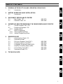
1
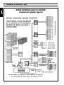
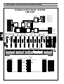
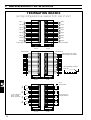
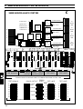
SM 40
Surveillance Centre
Instructions for use
Eng
LBB 1360 & LBB1370
Philips
Communication &
Security Systems
TABLE OF CONTENTS
1.
GENERAL INTRODUCTION AND OPERATING PRINCIPLES
1.1
Introduction
2.
SYSTEM UNPACKING AND INSTALLATION
2.1
Introduction
3.
SM 40 BASIC SURVEILLANCE CENTRE
3.1
Basic System - BS
3.2
Extension Frame - EF
LBB 1370
LBB 1360
4.
OPERATING AND PROGRAMMING THE SM40 SURVEILLANCE CENTRE
4.1
Central Processor Card - CPC
4.2
Display and Keyboard - DK
4.2.1 Display readout
4.3
SM40 Programmng
4.3.1 User Programming Menu
4.3.2 Installer Programming Menu
5.
SM40 MODULES
5.1
Interconnection Board - IB
5.2
Termination Board
5.3
Pilot-tone Generator Card (PGC)
5.4
Surveillance Switch Card (SSC)
5.5
Loudpeaker Surveillance Board (LSB)
5.6
Amplifier Surveillance Board (ASB)
5.7
Control Relay Card (CRC)
5.8
Termination Board (TB)
6.
1
2
3
LBB 1369
LBB 1374
LBB 1367
LBB 1368
LBB 1356
LBB 1377
4
TECHNICAL DATA
5
6
1
1.
GENERAL INTRODUCTION
SM40 SURVEILLANCE CENTRE
(maximum system layout)
1
2
1.
1.1
GENERAL INTRODUCTION
Introduction to the SM40 Surveillance Centre
In large public address distribution systems, which often play a key role in alarm and evacuation
installations, it is vital that the correct functioning of the large number of amplifiers and loudspeakers used
can be verified.
The SM40 Surveillance Centre is designed to monitor the status of amplifiers, loudspeakers, and cabling in
large PA systems. Because it pinpoints any failures in the system, it saves a great deal of time, minimising
repair costs as well as ensuring that the system is fully functional at the earliest possible moment.
On detection of a malfunction, error messages are generated automatically, giving the precise time and
location of the fault. These messages can either be relayed to the system’s LCD display, or sent to an external
printer for a permanent hard-copy record of the malfunctions. The messages can also be linked to warning
lamps, buzzers, or personal paging units, alerting security and maintenance personnel.
The possibility also exists to automatically switch in a spare amplifier in place of an amplifier which becomes
faulty.
A pilot tone signal is generated which is inserted into the Test inputs of Philips SQ45 power amplifier range.
The Surveillance Centre is able to scan for the presence of this signal in up to 4096 monitoring devices,
located in strategic places (at amplifier outputs, loudspeaker cabling junction boxes, inside loudspeaker
enclosures) throughout a PA distribution system. It can also receive ‘internal error’ information from an
SM40 Routing System itself, as well as responding to external sensing devices such as smoke detectors and
micro switches.
Being controlled by a microprocessor, the system is particularly flexible, specific functions being easily
programmed and changed to allow for alterations in the PA system configuration and surveillance
requirements.
Because the system is built around 19-inch rack mounted Euro Card circuit boards, expansion or alterations
to the system are quickly and easily carried out.
A total Surveillance Centre would comprise:
- 19-inch rack unit, containing a microprocessor controlled SM40 Surveillance Centre
- 100V loudspeaker line, and low voltage loudspeaker, monitoring devices; external warning devices
(lamps, buzzers, etc.)
- printer, or computer/printer combination.
All SM40 Surveillance Centre internal wiring is particularly installer friendly due to the ‘Quick Fit’
connectors used.
Standard twisted two core screened microphone cable is used to carry data and 15V power between the
system and the interlinked Amplifier/Loudspeaker Surveillance Boards.
All SM40 Surveillance Centres are built around the LBB 1370 Basic (starter) System, which is able to
sequentially scan 8 Test Lines, each containing up to 128 monitoring devices; receive error input from
2 external sources, activates several relay error sets and synchronises the real-time clock.
The single 19-inch rack frame, capable of holding 9 circuit cards, has enough room to accomodate the Basic
System plus 5 extra cards. Adding these cards expands the system, enabling it to feed more amplifiers with
the Pilot Test Tone; scan a greater quantity of Test Lines and/or receives a larger amount of error inputs
from external devices. However the system is limited by the number of Termination Boards installed.
When a system’s requirements exceed the space offered in a single rack frame, or extra termination boards
are required the SM40 Extension Frame LBB 1360 is available. These frames can be linked together to
expand the system.
3
1
2. UNPACKING AND INSTALLATION
SURVEILLANCE BASIC SYSTEM
LBB 1370
TB1
TB3
2
TB4
TB5
I/O Board
Pilot-tone Generator Card
Processor card
PE 1268
PE 1141
Control Relay Card
Surveillance Switch Card
RS 232
connection
FRONT TOP VIEW
INTERCONNECTION BOARDS
PGC
CPC
CRC
1268/10
SSC
1
1
1
1
1
1
1
1
1
1
8
10
8
10
8
10
8
10
8
10
8
10
8
10
8
10
8
10
8
10
17
17
17
17
17
17
17
17
17
17
21
21
21
21
21
21
21
21
21
21
25
25
25
25
25
25
25
25
25
25
30
30
30
30
30
30
30
30
30
30
ba
TEST SIGNALS
U-1
4
ERROR ERROR
OUTPUT INPUT
TERMINATION BOARDS
(REAR VIEW)
4
2
TEST LINES
1141/52
2. UNPACKING AND INSTALLATION
2.1
SM40 Surveillance Centre - Unpacking and installation
In order to ensure that your SM40 Surveillance Centre functions properly, please follow these few simple
instructions after unpacking your unit.
1
Carefully check the enclosed system components for physical damage caused during shipping. Any
complaints should be made immediately to the shipping company.
2
Mount the Basic System frame in the appropriate position in the 19-inch rack unit (not higher
than shoulder height, so that the display and keyboard can be clearly seen).
3
Extension Frames are available to expand the Basic System into a larger system. These should now
be mounted, and wired according to the appropriate wiring diagrams.
4
Mount the amplifiers and auxiliary equipment in the rack(s).
If power amplifiers are mounted beneath SM40 frames, a heat shield should be installed above
them to deflect hot air currents.
5
Taking care to avoid earth (ground) loops, wire the mains power to the units. The SM40
Surveillance Centre will operate successfully on mains voltages from 175 V to 264 V when tapped
for 220 V, and from 90 V to 140 V when tapped for 110 V. Be sure to check that your system is
wired for the correct mains voltage.
Caution: When tapping the system for the correct mains voltage, refer to the documentation
supplied with the SM40 system.
NOTE: Because it is possible to touch the mains voltage terminals when the frame back panels are
opened, it is advisable not to turn the power on at this stage.
6
Open the back panel of the Basic system, and check that all of the connectors on the
Interconnection Board and Termination boards are firmly in place. If, in the unlikely event that one
of the connectors has become disconnected, refer to the enclosed basic system wiring diagram.
7
Refering to Termination Board illustrations in chapter 10, wire the Test Lines, Amplifier Test
Inputs, and Error Inputs/Outputs, to the screwblock connectors. If a printer or computer is to be
used with the system, it should be wired to the RS232 serial interface socket at this time
8
Plug the screwblock connectors into the termination boards, ensuring that they are in the correct
locations.
9
Open the front panel of the rack frame and gently push each of the circuit cards to make sure that
they are all firmly connected to the Interconnection Board.
10
If, after double checking that all of the mains power and signal wiring is correct, and that the
system is adequately earthed, switch on the mains power to the rack.
5
2
3. SM 40 BASIC SYSTEM AND EXTENSION FRAME
SURVEILLANCE BASIC SYSTEM
LBB 1370
Error
indication
CRC
16
U-1
PGC
9
CPC
15V
SSC
1
1
1-8
RS232
PGC
RS232
2 LSB/ASB error
1 General error
PE
TB
8
3
5 Printer error
4 System error
3 External error
CPC
CRC
Power supply
1268/10
SSC
1
1
1
1
1
1
1
1
1
1
8
10
8
10
8
10
8
10
8
10
8
10
8
10
8
10
8
10
8
10
17
17
17
17
17
17
17
17
17
17
21
21
21
21
21
21
21
21
21
21
25
25
25
25
25
25
25
25
25
25
30
30
30
30
30
30
30
30
30
30
ba
L-2
U-1
TEST SIGNALS
To
8x128
LSBs
Communication &
L-1
ERROR
ERROR ERROR
OUTPUT OUTPUT INPUT
TEST LINES
INTERCONNECTION BOARD WIRING AS VIEWED FROM REAR OF RACK UNIT
TEST SIGNALS
ERROR OUTPUT
9
10
11
12
13
14
15
1
2
3
4
5
6
General
Printer
ASB/LSB
7
System
16
8
ERROR
INPUT
TEST LINES
1 Clock sync.
2
3
External
TERMINATION BOARD WIRING AS VIEWED FROM REAR OF RACK UNIT
6
1
2
3
4
5
6
7
8
1141/52
3. SM 40 SURVEILLANCE BASIC SYSTEM
3.1
SM40 Surveillance Basic System
LBB 1370
Self contained, fully operational system, around which all SM40 Surveillance Centres are built.
Comprises 4 circuit cards, mounted in a single 19-inch rack frame.
The Surveillance Basic (starter) System is the heart of the SM40 Surveillance Centre. When supplemented
with a variety of Euro-cards and PCB’s, a wide range of system configurations are possible, and many
different application needs are succesfully met.
Containing, in its single rack frame, the Display and Keyboard, and the Central Processor Card (CPC);
(along with its other circuit cards) the Basic System is a self contained, fully working unit in its own right.
Being supplied with one Surveillance Switch Card (SSC) the system is able to sequentially scan 8 seperate
test lines, each having upto 128 Amplifier Surveillance Boards (ASB’s) and/or Loudspeaker Surveillance
Boards (LSB’s) connected.
The +15V required to power each test line in turn is provided by the in-built PE 1268/10 power
supply.unit.
The Basic System is also able to display error information generated by 2 external sources and clock
synchronisation using a single contact.
The communication PCB can send information generated by the CPC, via its RS232 port, to a printer or a
computer for the production of detailed hard copy of all monitored errors. The control relay card may be
used to activate external warning devices (lamps, buzzers, etc.) when an error occurs.
When a centre’s requirement exceed the facilities available in the Surveillance Basic System, further circuit
cards (plus the extension frames LBB 1360 necessary to accomodate them) are ordered, expanding the
system to meet specific application needs.
Because the Surveillance Basic system is supplied fully wired, adjusted, tested, and mounted in its own
19-inch rack unit, ready for use, it is an ideal model from which to build a larger system.
Units included with Basic System LBB 1370:
1x
1x
1x
1x IB
4x TB
1x CPC
Single 19-inch Rack Frame
Power Supply +15V/-15V/+5V
Power Supply +15V
Interconnection Board
Termination Boards
Central Processor Card + I/0 +
Surveillance System Software
1x CRC Control Relay Card
1x SSC Surveillance Switch Card
1x PGC Pilot Tone Generator Card
Optional Euro-Cards:
CRC
PE 1141/52 SSC
PE 1268/10 PGC
TB
LBB 1377/00
Control Relay Card
Surveillance Switch Card
Pilot Tone Generator Card
Termination Board
Optional PCB’s:
LBB 1356/00
LBB 1374/00 Loudspeaker Surveillance Board
LBB 1369/00 Amplifier Surveillance Board
LBB
LBB
LBB
LBB
1356
1374
1369
1377
LBB 1367
LBB 1368
7
3
3. SM 40 BASIC SYSTEM AND EXTENSION FRAME
SURVEILLANCE BASIC SYSTEM LBB 1370
Plus 1 EXTENSION FRAME LBB 1360
INTERCONNECTION BOARD WIRING AS VIEWED FROM REAR OF RACK UNIT
PGC
CPC
PGC
CRC
SSC
SSC
SSC
PE 1268/10
SSC
1
1
1
1
1
1
1
1
1
1
8
10
8
10
8
10
8
10
8
10
8
10
8
10
8
10
8
10
8
10
17
17
17
17
17
17
17
17
17
17
21
21
21
21
21
21
21
21
21
21
25
25
25
25
25
25
25
25
25
25
30
30
30
30
30
30
30
30
30
30
U-1
ba
TEST SIGNALS
3
25 - 32
TEST SIGNALS
17 - 24
PGC
9 - 16
1-8
PGC
TEST LINES
ERROR ERROR
OUTPUT INPUT 25 - 32
17 - 24
PGC
CRC
CRC
TEST LINES
9 - 16
CRC
1
1
1
1
1
1
1
1
1
8
10
8
10
8
10
8
10
8
10
8
10
8
10
8
10
8
10
8
10
17
17
17
17
17
17
17
17
21
21
21
21
21
21
21
21
25
25
25
25
25
25
25
25
25
30
30
30
30
30
30
17
17
20
20
30
ba
TEST SIGNALS
73 - 80
30
L-4
TEST SIGNALS
65 - 72
57 - 64
TEST SIGNALS
49 - 56 41 - 48
33 - 40
L-2
L-1
ERROR OUTPUT ERROR OUTPUT
25 - 32
17 - 24
9 - 16
SIDE VIEW FRAMES
Basic frame
Front
Rear
Extension frame
8
LBB 1360
+
30
30
L-3
1-8
CRC
1
24
PE 1141/52
1-8
3. SM 40 BASIC SYSTEM AND EXTENSION FRAME
3.2
Extension Frame
LBB 1360
Single 19-inch rack frame, capable of holding 10 SM40 circuit cards. Complete with power supply, and
one Interconnection and Termination Board.
A single rack frame, capable of holding, and interconnecting 10 SM40 circuit cards, has enough room to
accomodate the Basic (starter) System, described elsewhere, plus additional Pilot-tone generator cards,
Control Relay Cards and Surveillance Switch Cards.
When the number of terminations boards required in an SM40 system exceeds the amount of space offered
in this single rack frame, Extension Frame LBB 1360, is available.
Units included with Extension Frame LBB 1360:
1x
1x
1x IB
1x TB
Single 19-inch rack frame
Power Supply Unit +15V/ -15V
Interconnection Boards
Termination Boards
PE1113/50
LBB 1377/00
These components, mounted in the 19-inch rack frame, are supplied tested, and wired to accept and power
up to 10 SM40 circuit cards.
SM40 EXTENSION FRAME
LBB 1360
TB1
PE 1113
FRONT TOP VIEW
9
3
3. SM 40 BASIC SYSTEM AND EXTENSION FRAME
SURVEILLANCE
BASIC FRAME
+15V supply & comm
1
8
Pilot-tone
1
16
Error
1
2
3
4
5
RS232
SSC
PGC
CRC
CPC
I/O
2
IC
supply
3
PE1268/10
Supply for
surveillance boards
PE1141/50
Supply for
eurocards
220 V
DATA BUS
ADDRESS BUS
CONTROL BUS
DISPLAY
BUFFER
X-tal.
5.068 MHz
MICROPROCESSOR
Z80 B
32K
EPROM
32K
RAM
REAL-TIME
CLOCK
X-tal.
32.768 KHz
2
IC
INTERFACE
RS232
I/O BOARD
Clock data 2
Clock data 3
DATA
CLOCK
serial/buffers
Clock data 4
Clock data 5
Clock data 6
CENTRAL PROCESSOR CARD
Communication
Clock data 1
2
IC
10
Comm.
4. OPERATING AND PROGRAMMING THE SM40 SURVEILLANCE CENTRE
4.1
Central Processor Card - CPC
Eurocard 10 x 22 cm with an ‘a b’ connector (2 x 32). A microprocessor which can scan over 4000
monitoring devices, and activate more than 100 relays, via the communication line.
At the heart of the SM40 Surveillance Centre is the Central Processor Card (CPC). Capable of sequentially
scanning 4096 monitoring devices; activating 64 SSC solid state relays, and 40 CRC relay sets; and sending
error information to a display, external computer, or printer; this is a powerful piece of equipment. It
provides a system of this type with a great amount of possibilities.
A Display & Keyboard mounted in the rack unit’s front panel, is used to display the scanning status and any
detected errors, and also to carry out the user programming.
When programming is complete the CPC returns to its normal scanning mode and, until a secret password
is entered, the keyboard has no influence on the processor.
The basic functions of the Central Processor Card are as follows:
SCANNING of Amplifier Surveillance Boards (ASB’s) and/or Loudspeaker Surveillance Boards (LSB’s).
This is done by sequentially sending 15V power to each of the 8 Test Lines of the Surveillance Switch Cards
(SSC’s) in turn, then sending communications data to each board in each line sequentially.
Translating the error data received from the ASB’s and LSB’s, along with external sensing devices, and
relaying this information to the display, or via the RS232 port, to a printer or external computer.
ACTIVATING of relays, to switch on external warning devices (lamps, buzzers, paging units, etc.) via
Control Relay Cards (CRC’s).
CHECKING of system hardware. The processor acts as a “watchdog”, continuously patrolling the SM40
Surveillance Centre hardware to check for errors, malfunctions or disconnections. If a problem exists,
information, stating which card is faulty, is relayed to the display or printer.
An automatic restore function is also incorporated, so that when an internal error occurs, the system will not
hang-up, and when an error is rectified no manual system reset is required.
REAL TIME CLOCK is built into the unit, and (in the program’s ‘Enable Print’ mode) is displayed on the
LCD, giving date, hours and minutes. When an error occurs, the current time and date are transmitted to
the printer. Synchronisation is via A17 on Surveillance Switch Cards No.1.
SERIAL INTERFACE. The standard RS232 serial interface connector mounted on a bracket on the frame,
and wired to the CPC, allows the system to communicate with a wide variety of personal, mini, and mainframe computers as well as direct to serial printers.
The communication has 8 data bits, and the baud-rate is selectable between 300, 1200, 2400, 4800 and
9600 baud.
This, and the other I/O port parameters, such as number of Stop Bits, and Parity can be set in the installer
programming menu.
SM40’s standard default parameters are:
2400 baud, 8 data bits, 1 stop bit, even parity.
A yellow LED, mounted on the front edge of the card indicates that the CPC is in communication with the
rest of the SM40 Surveillance Centre, and 1 green LED indicates that adequate supply voltage is present.
The CPC has additional driver stages for the communication lines of 5 of the Extension Frames used to
expand the Surveillance Basic System.
11
4
4. OPERATING AND PROGRAMMING THE SM40 SURVEILLANCE CENTRE
DISPLAY & KEYBOARD
* * * SM40 SURVEILLANCE SYSTEM * * *
DAY:XX-XX
TIME:XX:XX
0
1
2
3
4
A
B
C
5
6
7
8
9
1
0
Break
Mute
1
0
Enter
Grey shaded keys are functional in the programming mode. i.e
USER MENU, INSTALLER MENU & SERVICE MENU
DISPLAY READOUTS AFTER ENTERING 'USER-MENU' PASSWORD (9, 6, ENTER)
>WELCOME TO SURVEILLANCE PROGRAMMING<
>> VERSION 1.21
DATE: XX-XX-XX <<
*USER MENU*
Scroll with 'ENTER'
PRESS '1' TO SELECT ERROR PRINTING
4
1
DIPSLAY OF ERRORS ON PRINTER
PRESS '0' TO DISABLE; '1' TO ENABLE: _
*USER MENU*
Scroll with 'ENTER'
PRESS '2' TO PRINT CURRENT ERRORS
2
*USER MENU*
Scroll with 'ENTER'
PRINTER NOT READY; PLEASE CHECK
*USER MENU*
Scroll with 'ENTER'
PRESS '3' TO SET REAL-TIME CLOCK
3
ENTER
DD-MM-HH:MM
XX-XX XX:XX
ENTER LAST 2 DIGITS OF CURRENT YEAR: XX
12
4. OPERATING AND PROGRAMMING THE SM40 SURVEILLANCE CENTRE
4.2
Display and Keyboard
A programming tool, containing a keyboard for user key assignment and a display which shows the
sequence of programming. Mounted in the front panel of the rack unit.
Users of the SM40 Surveillance Centre are able to program and make changes to the functions of their
system, quickly and easily, with the aid of the Display And Keyboard. This is a simple programming tool
comprising a 24 key keyboard and a 2x40 character lcd display which shows the sequence of programming.
SM40 KEY FUNCTIONS
0-9
Numeric keys to type-in password; select
programs and functions; and to insert the
time and date in the User Programming
menu.
Moves the cursor 1 position to the right
when setting the real-time clock in the User
Programming menu.
Moves the cursor 1 position to the left when
setting the real-time clock in the User
Programming menu.
Non-functional
Non-functional
1
Non-functional
0
Non-functional
1
Non-functional
0
Non-functional
Mute
Non-functional
A
Non-functional
B
Non-functional
C
Non-functional
Break
In most cases this key will abort a command
and return the user to the main menu for the
next programming sequence without any new
information being stored. When in the main
menu, pressing will return the system to the
normal scan mode.
Enter
Enters numerical inputs into the memory and
moves to the next program stage, or at the
end of a program sequence; to the main
menu ready for the next program.
When programming is completed, the system returns to its
normal scanning mode and, until the correct password is
entered, the keyboard has no influence on the processor,
thus guarding the system from unauthorized tampering.
The unit is mounted in the rack units’ front panel, which
may be flipped up, locking automatically in a horizontal
position. This is an ideal angle from which to view and
operate the unit.
13
4
4. OPERATING AND PROGRAMMING THE SM40 SURVEILLANCE CENTRE
4.2.1
Display readout
During the remainder of this chapter, specific contexts (status) and user actions are shown in the left
column, and possible display results are shown in the right column. Characters between quotes (e.g. ‘Key’)
denote keyboard inputs, and occurrances of XX and YY in any displays shown in the right column denote
information which is dependant on the system configuration, or entered by the user.
Status / Action
When the SM40 system is powered up, either one of the following two displays is shown:
Result / Remarks
When memory was cleared the display shows:
* * * SYSTEM MUST BE PROGRAMMED * * *
* * *
When the system was installed previously,
the display shows:
This message will disappear after 2-seconds,
and the system will start scanning.
When scanning and error printing are enabled
(refer to User Programming Menu) the
display shows:
The second display line is used to display the
current date and time.
4
When scanning and error printing are
disabled (refer to User Programming Menu)
the display shows:
The second display line is used to display
errors. Errors are indicated one by one in a
continuous cycle.
Loudspeaker/amplifier errors are displayed as
follows:
External errors are displayed as follows:
GO TO INSTALLER MENU
* * * SM40 SURVEILLANCE SYSTEM * * *
DATE:XX-XX
TIME:XX:XX
SCANNING ZONE: XX UNIT XX
DATE: XX-XX
SCANNING ZONE: XX UNIT: XXX
SCANNING ZONE: XX UNIT: XXX
ERROR IN ZONE: XX UNIT: XXX
SCANNING ZONE: XX UNIT: XXX
<ERROR> EXTERNAL INPUT: XX
SCANNING ZONE: XX UNIT: XXX
<ERROR> SWITCH CARD: XX
System errors are displayed as follows:
SCANNING ZONE: XX UNIT: XXX
<ERROR> RELAY CARD: I-XX
SCANNING ZONE: XX UNIT: XXX
<ERROR> RELAY CARD: II-XX
14
* * *
TIME: XX:XX
4. OPERATING AND PROGRAMMING THE SM40 SURVEILLANCE CENTRE
The printer produces a listing of errors as follows:
<ERROR>
<ERROR>
<ERROR>
<ERROR>
<ERROR>
DATE:XX-XX
DATE:XX-XX
DATE:XX-XX
DATE:XX-XX
DATE:XX-XX
TIME:XX:XX
TIME:XX:XX
TIME:XX:XX
TIME:XX:XX
TIME:XX:XX
ZONE:XX
ZONE:XX
ZONE:XX
ZONE:XX
ZONE:XX
UNIT:XXX
UNIT:XXX
UNIT:XXX
UNIT:XXX
UNIT:XXX
If the <ERROR> is rectified the same message is sent to the printer followed by: ‘RECOVERED’.
ERROR INDICATION
Errors are communicated to external indication devices (i.e warning lamps, alarm buzzers, etc..) via
relay cards.
Relay cards I, 1,2,3 and 4 indicate errors in zones 1 to 32
Relay cards II, 1, indicates general error indication with the following indications:
Relay 1 is activated when any error occurs.
Relay 2 is activated when a loudspeaker/amplifier error occurs.
Relay 3 is activated when an external error occurs.
Relay 4 is activated when a system error occurs.
Relay 5 is activated when a printer error occurs.
4
15
4. OPERATING AND PROGRAMMING THE SM40 SURVEILLANCE CENTRE
4.3
SM40 USER PROGRAMMING
Specific contexts (status) and user actions are shown in the left column, and possible display results are
shown in the right column. Characters between quotes (e.g. ‘Key’) denote keyboard inputs, and occurrances
of XX and YY in any displays shown in the right column denote information which is dependant on the
system configuration, or entered by the user.
Unless stated otherwise, ‘Enter’ stores typed information in the memory. ‘Break’ aborts a command without
storing new information.
4.3.1
SM40 SURVEILLANCE USER PROGRAMMING
Status / Action
When the system is ‘powered up’, one of the
next two displays is shown:
The first display shows when the memory has
been cleared. The system is inoperative until
installed (via the Installer menu).
The second display shows when the system is
installed.
To enter the user programming mode, press
keys ‘9’, ‘6’, followed by the ‘Enter’ key. The
display shows:
Result / Remarks
* * * SYSTEM MUST BE PROGRAMMED * * *
* * * GO TO INSTALLER MENU * * *
* * * SM40 SURVEILLANCE SYSTEM * * *
DATE:XX-XX
TIME:XX:XX
> WELCOME TO SURVEILLANCE PROGRAMMING <
>> VERSION X.X
DATE XX-XX-XX <<
The ‘welcome’ display shows the current software version and its release date. After
three seconds this message is cleared and the first programming mode is displayed.
The first programming mode is displayed as follows:
4
*USER MENU*
Scroll with 'ENTER'
PRESS '1' TO SELECT ERROR PRINTING
Display after pressing ‘1’.
DISPLAY OF ERRORS ON PRINTER
PRESS '0' TO DISABLE; '1' TO ENABLE
The current selection will be displayed. Selecting ‘0’ will show all errors displayed
on the lower line. Selecting ‘1’ will send all errors to the printer, with the lower line
showing the current date and time
Display after selection:
*USER MENU*
Scroll with 'ENTER'
PRESS '2' TO PRINT CURRENT ERRORS
Pressing ‘2’ will produce a printout of loudspeaker, external, and system errors
(regardless of the settings in user menu ‘1’ shown above). The header will show the
date and time.
This function is useful for incidental printing, when no permanent printer is
connected. If the printer is not powered, off-line, or the serial board parameters are
not correctly programmed (via the installer program), the display will show (see
next page):
16
4. OPERATING AND PROGRAMMING THE SM40 SURVEILLANCE CENTRE
Status / Action
Result / Remarks
(Continued from previous page...)
PRINTER NOT READY; PLEASE CHECK
Printing will begin when the printer problem has been solved.
Pressing ‘Break’ will return the system back to
display the Main Menu. The display will
show:
*USER MENU*
Scroll with 'ENTER'
PRESS '3' TO SET REAL TIME CLOCK
Display after pressing ‘3’.
ENTER
DD-MM HH:MM
XX-XX XX:XX
The clock can be set by either entering the complete time or by shifting the cursor
to the digit that must be altered using the single arrow keys
and .
After pressing ‘Enter’ the display shows:
ENTER LAST 2 DIGITS OF CURRENT YEAR: XX
After entering the 2 digits and after pressing ‘Enter’ the display shows:
*USER MENU*
Scroll with 'ENTER'
PRESS 'BREAK' TO EXIT PROGRAMMING
4
After pressing ‘Break’ the system will return to its normal scanning mode.
USER PROGRAMMING IS NOW COMPLETE.
17
4. OPERATING AND PROGRAMMING THE SM40 SURVEILLANCE CENTRE
4.3.2
SM40 SURVEILLANCE INSTALLER PROGRAMMING MENU
Status / Action
To enter the INSTALLER programming
mode, press keys ‘8’, ‘1’, followed by the
‘Enter’ key. Ther display shows:
Result / Remarks
> WELCOME TO SURVEILLANCE PROGRAMMING <
>> VERSION X:XX
DATE DD-MM-YY <<
The ‘welcome’ display shows the current software version and its release date. After
three seconds this message is cleared and the first programming mode is displayed.
Programs 1, 2 and 3 are identical to that of the User Programming. In the ‘installer
mode’ the first display is as follows:
Display if system is installed:
*INSTALL MENU*
Scroll with 'ENTER'
PRESS '4' TO STORE SYSTEM HARDWARE
To enable the system to operate correctly, the current hardware configuration must
be stored. This is done by pressing key ‘4’.
Display after pressing ‘4’.
*INSTALL MENU*
Scroll with 'ENTER'
STORING HARDWARE CONFIGURATION
The display is only shown during storing, then continues as follows:
4
*INSTALL MENU*
Scroll with 'ENTER'
PRESS '5' TO DISPLAY SYSTEM SETUP
After pressing ‘5’ the display shows:
SWITCH CARDS: XX XX XX XX
Display after pressing ‘Enter’.
RELAY CARDS I: XX XX XX XX
II: XX XX XX XX
Display after pressing ‘Enter’.
I/O BOARD MOUNTED: YES
Display after pressing ‘Enter’.
*INSTALL MENU*
Scroll with 'ENTER'
PRESS '6' FOR AUTO-STORE OF ALL UNITS
This program stores all the loudspeaker/amplifier surveillance boards which are
present in the system’s memory. However a zone will only be scanned if:
- The corresponding surveillance switch card is present.
- The unit with adddress ‘1’ is connected to that zone and recognised.
18
4. OPERATING AND PROGRAMMING THE SM40 SURVEILLANCE CENTRE
SM40 SURVEILLANCE INSTALLER PROGRAMMING MENU
Status / Action
Result / Remarks
After pressing ‘6’ the display shows:
SCANNING ZONE:XX
UNIT:XXX
All the relevant zones will be scanned and the units present will be stored in
memory.
When ready the display will show:
TOTAL SYSTEM SCAN TIME: XX MIN XX SEC
Press 'ENTER' to continue . . . .
This is the time interval between two scans of the same unit. This information is
relevant for ‘priority scanning’’ programming.
Display after pressing ‘Enter’:
*INSTALL MENU*
Scroll with 'ENTER'
PRESS '7' TO ADD/DELETE UNITS
This program is used to manually add or delete surveillance units.
Display after pressing ‘7’:
ENTER ZONE NUMBER:
Display after input of zone number (1-32)
and after pressing ‘Enter’.
Display after input of zone number (1-128)
and after pressing ‘Enter’.
Display after pressing ‘0’, if the selected unit
was present.
Display after pressing ‘1’, if the selected unit
was present.
ZONE: XX
ENTER UNIT NUMBER
4
ZONE: XX UNIT: XXX
PRESS '0' TO DELETE; '1' TO ADD
ZONE: XX UNIT: XXX
PRESS '7' TO ADD/DELETE UNITS
DELETED
ZONE: XX UNIT: XXX
PRESS '7' TO ADD/DELETE UNITS
ADDED
Display if the selected unit was NOT present.
ZONE: XX UNIT: XXX
ENTER UNIT NUMBER
NOT FOUND
At this stage in the programming a new unit number may be entered, and the
proces repeated.
Pressing ‘Break’ will return to ‘ENTER ZONE NUMBER’.
Pressing ‘Break’ again will return to the main menu.
19
4. OPERATING AND PROGRAMMING THE SM40 SURVEILLANCE CENTRE
SM40 SURVEILLANCE INSTALLER PROGRAMMING MENU
Status / Action
Result / Remarks
The display shows the following:
*INSTALL MENU*
Scroll with 'ENTER'
PRESS '8' TO SHOW ALL UNITS
Display after pressing ‘8’.
DISPLAY OF ALL UNITS FOUND
PRESS '1' FOR PRINTER; '2' FOR DISPLAY
Pressing ‘1’ will send a list of stored units (zone-by-zone) to the printer.
The header will show date and time.
Display after pressing ‘2’.
ENTER ZONE NUMBER: XX
Display after input of zone number (1-32)
and after pressing ‘Enter’.
ZONE: XX UNITS CONNECTED
XXX XXX XXX XXX XXX XXX XXX XXX XXX XXX
Pressing ‘Enter’ will show the next 10 units. Pressing ‘Break’ will repeat zone input
request, pressing ‘Break’ again will return to main menu. The display will show:
*INSTALL MENU*
Scroll with 'ENTER'
PRESS '9' TO SET PRIORITY SCANNING
4
This program cause the scanning sequence to be interrupted, while zone 1 or 2
(or both) are scanned at a programmed time interval
Display after pressing ‘9’.
PRIORITY SCANNING
PRESS '0' TO DISABLE; '1' TO ENABLE
Pressing ‘0’ will disable priority scanning and return to main menu.
Display after pressing ‘1’.
Display after input of zone ‘1’ or ‘2’ and
‘Enter’.
PRIORITY SCAN OF ZONE (1 OR 2):
PRIORITY SCAN OF ZONE (1 OR 2):X
ENTER INTERVAL TIME (O-9 MIN.):
Input of ‘0’ minutes will disable priority scanning for that zone. Input of any other
time (1-9 minutes) will cause an extra scan of that zone to occur at the
programmed time interval. The current zone scan however will finish first.
20
4. OPERATING AND PROGRAMMING THE SM40 SURVEILLANCE CENTRE
SM40 SURVEILLANCE INSTALLER PROGRAMMING MENU
Status / Action
Result / Remarks
The scanning of a priority zone will be indicated by an ‘asterix’ in the upper right
corner of the display.
After entering the ‘interval time’ and after pressing ‘Enter’ the display will repeat
the zone number request. Pressing ‘Break’ will return to the main menu.
The display shows the following:
*INSTALL MENU*
Scroll with 'ENTER'
PRESS 'A' TO SET PROGRAM SHUT-OFF TIMER
During installer programming scanning is halted. The program ‘Shut-off Timer’
causes the system to automatically exit programming, and to start scanning at the
preprogrammed time after the last key stroke.
Display after pressing ‘A’.
PROGRAMMING MODE SHUT-OFF TIMER
PRESS '0' TO DISABLE; '1' TO ENABLE
Pressing ‘0’ will disable the timer and return to main menu.
Display after pressing ‘1’.
ENTER TIME (1-9) MINUTES BETWEEN
LAST KEYSTROKE AND SHUT-OFF: 3
After input of the desired time, and after pressing ‘Enter’, the display will return to
the main menu. The display will show.
*INSTALL MENU*
Scroll with 'ENTER'
PRESS 'B' TO SET I/O PARAMETERS
This program will set the serial (printer or P.C.) parameters. If the memory was
previously cleared, the serial port will be set by default at 2400 baud, 8 databits,
1 stop bit and even parity.
Display after pressing ‘B’.
SELECT BAUD RATE (1-5): 3
1=300 2=1200 3=2400 4=4800 5=9600
Display after entering ‘1’, ‘2’, ‘3’, ‘4’, or ‘5’
and after pressing ‘Enter’.
SELECT NUMBER OF STOPBITS (1-2): 1
Display after entering ‘1’ or ‘2’.
PARITY SELECTION (1-3): 1
1 = EVEN 2 = ODD 3 = NO PARITY
After entering ‘1’, ‘2’, or ‘3’ and ‘Enter’, the display returns to the main menu.
21
4
4. OPERATING AND PROGRAMMING THE SM40 SURVEILLANCE CENTRE
SM40 SURVEILLANCE INSTALLER PROGRAMMING MENU
Status / Action
Result / Remarks
The display shows the following:
*INSTALL MENU*
Scroll with 'ENTER'
PRESS 'C' TO CLEAR ALL MEMORY
Because this program clears the complete memory, caution must be taken. The
display after pressing ‘C’ is as follows:
CLEAR ALL MEMORY: ARE YOU SURE ?
'0' CLEARS; ANY OTHER KEY ABORTS
Pressing any key except ‘0’ will return to the main menu
Pressing ‘0’ will display:
* * * WARNING * * * MEMORY CLEARED
After 3 seconds the following message is displayed
* * * SYSTEM MUST BE PROGRAMMED * * *
* * * GO TO INSTALLER MENU * * *
The system is now no longer in the programming mode.
The display if the memory was not cleared.
4
*INSTALL MENU*
Scroll with 'ENTER'
PRESS 'BREAK' TO EXIT PROGRAMMING MODE
Pressing ‘Break’ now will return to the normal scan mode.
22
4. OPERATING AND PROGRAMMING THE SM40 SURVEILLANCE CENTRE
This page has been left blank intentionally
4
23
5. SM40 SURVEILLANCE CENTRE MODULES
BOARD MOUNTED IN
SURVEILLANCE BASIC FRAME
5
24
5. SM40 SURVEILLANCE CENTRE MODULES
5.1
Interconnection board (IB)
Interconnection board for 10 SM40 Eurocards. Eurocard pressfit a + b (2 x 32) connectors.
Mounted at the rear of the 19-inch rack frame.
In any sophisticated communications system, convenient and dependable interconnection of the various
component units is vital.
The use of the Interconnection Board (IB) gives the SM40 Surveillance Centre both reliability and a great
deal of flexibility.
One IB is mounted at the rear of each 19-inch frame unit, and contains 10 Eurocard ‘Pressfit’ connectors of
the ‘a+b’ (2x32) format, into which 9, SM40 Surveillance Centre circuit cards can be plugged into the Basic
System Frame, and 10 in the Extension Frames (see frame layout drawings in Chapters 1 & 3.2).
The SM40 circuit card slides along rails within the frame unit and, with a light extra push, is mated securely
with the IB.
Removal of a card is done in the same way; a gentle tug with the special tool supplied, and the card then
slides out of the frame unit for service.
Each connector on the IB is universal, so that the cards may be located in the any position within the frame,
making alteration or expansion of the system both easy and economical. Even so, a logical positioning of the
circuit cards should be observed.
The system configuration should determine the position of the cards in the rack frames.
Some examples of typical systems, and the position of the cards in the frames are shown at the end of this
manual.
The power supply and reference signals, common to all of the circuit cards, are carried on rails printed on
the IB, but because the SM40 system has such a wide range of configuration possibilities, a certain amount
of cross-wiring between circuit cards is necessary.
This is easily accomplished by terminating the individual connector wires or flat cables with female Pressfit
connectors. These are then pushed onto the pins of the Eurocard connectors which are exposed on the rear
side of the IB.
Interconnection between the IB and the Termination Boards (TB’s) is also accomplished using flat cables
fitted with female ‘Pressfit’ connectors.
Located between the 10 connectors, on the rear of the IB, are Pressfit (2x8) connector blocks, whose
function is to join certain contacts of adjacent cards together.
Small Pressfit jumper plugs are used for this purpose (making the time consuming use of a soldering iron
unnecessary).
This ‘through connection’ of boards is necessary when using more than one Surveillance Switch Card (SSC)
in a frame (see System examples in Chapter 16).
25
5
26
PSU
DIG
I2C 1
PSU
REF
COMM
R/T
I/O
I2C 6
I2C 5
IC4
2
I2C 3
IC2
2
+15V
+15V
SCL
+5V
+5V
+5V
TXD
RTS
GND
SCL
SCL
SCL
SCL
SCL
a
IIC
IIC
IIC
PSU
ZONE 9
ZONE 10
ZONE 11
ZONE 12
ZONE 13
ZONE 14
ZONE 15
ZONE 16
+15V
+15V
- 15V
- 15V
b
1
2
3
4
5
6
7
8
9
10
11
12
13
14
15
16
17
18
19
20
21
22
23
24
25
26
27
28
29
30
31
32
+15V
+15V
- 15V
- 15V
a
PILOT TONE
GENERATOR CARD
I2C 1
PSU.
EXT.
ERROR
INPUT
IN for
TEST
LINE
FEED
+15V
to
TEST
LINES
1
2
3
4
5
6
7
8
9
+15V 10
11
12
13
14
15
16
2
17
18
19
20
+5V 21
+5V 22
23
SDA 24
25
26
27
28
29
30
31
32
1
2
3
4
5
6
7
8
b
SCL
+5V
+5V
1
3
DATA
+15V
1
2
3
4
5
6
7
8
a
SURVEILLANCE
SWITCH CARD
DATA
TO
TEST
LINES
PSU
I2C 1
PSU.
MAKE
BREAK
MAKE
BREAK
MAKE
BREAK
MAKE
BREAK
MAKE
BREAK
MAKE
BREAK
MAKE
BREAK
MAKE
BREAK
1
2
3
4
5
6
7
8
9
5
10
5
11
6
12
6
13
7
14
7
15
8
16
8
17
18
19
20
+5V 21
+5V 22
23
SDA 24
25
26
27
+15V 28
+15V 29
-15V 30
-15V 31
32
1
1
2
2
3
3
4
4
b
+15V
+15V
-15V
-15V
SCL
+5V
+5V
5
5
6
6
7
7
8
8
1
1
2
2
3
3
4
4
a
CONTROL RELAY
CARD
PRINTED CIRCUIT BOARDS CONNECTOR PIN CONFIGURATION
SDA 1
2
SDA 3
4
SDA 5
6
SDA 7
8
9
SDA 10
11
RXD 12
CTS 13
14
15
+15V 16
17
18
19
+5V 20
+5V 21
+5V 22
23
SDA 24
25
26
27
+15V 28
+15V 29
30
31
32
b
ZONE 1
ZONE 2
ZONE 3
ZONE 4
ZONE 5
ZONE 6
ZONE 7
ZONE 8
5
CENTRAL PROCESSOR CARD
5. SM40 SURVEILLANCE CENTRE MODULES
1
2
3
4
5
6
7
8
9
10
11
12
13
14
15
16
17
18
TO EXTERNSION FRAME
RIBBON CABLE
RS232
PGC
21
1
1
4
5
6
7
1
2
1
CPC
1
2
3
4
5
6
7
8
9
10
11
12
13
14
15
16
17
18
19
21
4
5
6
7
8
9
10
11
12
13
14
15
16
17
18
19
21
1
2
SSC
RIBBON CABLE
= Jumper
1
2
3
4
5
6
7
8
9
10
11
12
13
14
15
16
17
18
19
SSC
1
2
3
4
5
6
7
8
9
10
11
12
13
14
15
16
17
18
19
PSU 2
Mains
+15V
PE 1268/10
5. SM40 SURVEILLANCE CENTRE MODULES
DETAILED VIEW OF INTERCONNECTIONS
TO EXTERNSION FRAME
TO PSU No.1
TO EXTERNSION FRAME
5
27
RIBBON CABLE
TO EXTENSION FRAME
5. SM40 SURVEILLANCE CENTRE MODULES
TERMINATION BOARDS
(wiring configurations as viewed from rear of unit)
Amp.9
Amp.1
Amp.10
Amp.2
Amp.11
Amp.3
Amp.12
Amp.4
Amp.13
Amp.5
Amp.14
Amp.6
Amp.15
Amp.7
Amp.16
Amp.8
To test inputs of amplifiers
To test inputs of amplifiers
1
16
1
To PGC
16
To PGC
Shielded cables
Shielded cables
Test lines with power supply
& communication to the LSB's
shield grounding to screwed
solder tag
1
16
1
To SSC
16
To SSC
Clock
synchronisation
5
1
2
To error indicators:
make = red LED
Break = green LED
3
4
1
2
3
Make
Break
4
5
6
Make
Break
7
8
9
Make
Break
10
11
12
Make
Break
1
16
To CRC
28
1
16
To SSC
Error inputs from
external detectors
5. SM40 SURVEILLANCE CENTRE MODULES
5.2
Termination board (TB) (max. 5 per 19-inch rack frame)
Connector board mounted on the 19-inch frame back panel, connecting:
a)
b)
c)
d)
e)
16 Pilot Tone Generator Card outputs to the ‘Test’ inputs of Philips power amplifiers.
The outputs of 2 Surveillance Switch Cards to 16 individual ‘Test Lines’.
8 Control Relay Card relay sets to remote warning devices.
11 Error inputs to 4 Surveillance Switch Cards.
1 clock synchronisation contact.
The task of the termination boards described here is to connect the circuit cards, located in the central rack
unit, to the amplifier inputs, monitoring boards and external warning devices which make up the external
part of the SM40 Surveillance Centre.
Five boards are mounted on the back panel of each rack frame, which hinges down to expose the boards for
service.
The use of ‘push-fit-support-studs’ to mount the boards onto the back panel makes fitting or removal a fast
and simple matter.
Each Termination Board can be connected to the Interconnection Board (IB) by flat cable and/or individual
wires fitted with female ‘Pressfit’ connectors.
External devices are wired as shown, to screw connector blocks which are plugged into sockets mounted on
the termination boards.
This has the advantage that if, for some reason, an SM40 rack frame, or a Termination Board, has to be
removed, the screw connector block is simply unplugged, leaving the periferal equipment wiring intact.
This avoids the tedious and risky business of rewiring the blocks in their original configurations.
Two of these connector blocks, each containing 16 screw connectors, are mounted on each Termination
Board.
A Termination Board is capable of carrying out one of (or a mixture of ) the following functions:
1 Connecting the 16 outputs of a Pilot Tone Generator Card to the ‘Test’ inputs of Philips power
amplifiers (SQ45).
2 Connecting the data communications and +15V power outputs of a Surveillance Switch Card to 8
individual ‘Test Lines’.
3 Connecting 8 Control Relay Card (CRC) relay sets to remote warning devices. The ‘make’ contacts to red
(‘ERROR’) warning lamps, buzzers, or paging units; and the ‘break’ contacts to green
(‘FUNCTIONING’) lamps.
4 Connecting 11 Error inputs from external closed contact switches (dedicated error relay in an SM40
Routing System, smoke alarm, micro-switch, etc.) to 4 Surveillance Switch Cards, plus 1 clock
synchronisation contact.
5
Position of termination boards on back panel
TB5
TB4
TB3
TB2
TB1
For testing
line screens
29
5. SM40 SURVEILLANCE CENTRE MODULES
PILOT TONE GENERATOR CARD LBB 1369
Level adjust
20 kHz
OSCILLATOR
Burst
1
2
Continuous
3
4
+
-
5
6
1
Balanced
outputs
1-8
7
8
8
+15V
0V
DC SUPPLY
STABILIZER
LEDs
-15V
9
10
11
12
13
9
Balanced
outputs
9 - 16
14
15
16
5
-15V
+15V
Level
adjust
R207
MP
1
2
3
X2
Burst
30
Continuous
16
5. SM40 SURVEILLANCE CENTRE MODULES
5.3
Pilot tone generator card (PGC)
LBB 1369
Eurocard 10 x 22 cm with an ‘ab’ connector (2 x 32) containing a 20 kHz
tone oscillator and 16 independent electronically balanced outputs. These
are connected to amplifier test inputs.
The SM40 Surveillance Centre uses an ultrasonic (20kHz) pilot tone, inserted at the specially developed test
input of the Philips SQ45 amplifier. This tone is then relayed to all the loudspeakers throughout the
corresponding zone. The Surveillance Centre checks for the presence of this tone at various strategic points
in the zone. If the tone is not present at a particular point, it is obvious that the normal audio signal is not
going to be broadcast at that point either.
In each card a single oscillator is used to drive 16 electronically balanced outputs, which are floating free of
earth (ground). One PGC therefore can feed 16 amplifiers/loudspeaker zones with pilot tone signals.
The Central Processor Card (CPC) does not control, and has no infuence upon, the Pilot Tone Generator
Card (PGC). Neither is the PGC connected to any other card in the system.
The only dependence that the card has on the system is the fact that it requires +/- 15 Volt powering, which
is normally supplied from either the Basic System or an Extension Frame. Because of this, the amount of
PGC’s used in a system is unlimited.
Two green leds, mounted on the front edge of the card, advise that adequate supply voltages are present.
In order for the system to operate correctly, it is essential that the Volume Adjust control (see board layout
illustration) is set so that 10V is measured at the 100V output tap of the SQ45 amplifiers. All SQ45
amplifier Input Sensitivity Switches should be in the 1000 mV position. One master switch on the Pilot
tone generator card then sets the sensitivity level for all SQ45 amplifiers.
5.3.1 Reduction of power dissipation in amplifiers
To reduce the power dissipation in amplifiers when surveillance is used, the Amplifier Surveillance Board
(LBB 1368/00), the Loudspeaker Surveillance Board (LBB 1367/00) and the Pilot Generator Card (LBB
1369/00) have been modified. The modification enables a 20kHz ‘burst-pilot-tone’ to be used instead of a
continuous 20 kHz ‘pilot-tone’. This feature can be selected by a jumper located on the Pilot Generator
Card. The modified type number versions are compatible with previous versions and can be used all together
in a single system.
Selecting ‘continuous mode’ or ‘burst-mode’
Using jumper X2 the following mode can be selected:
Continiuous mode:
X2 in position 2-3 (output frequency 20kHz ±1kHz).
Burst-mode:
X2 in position 1-2 (output frequency 20kHz ±1kHz).
20kHz present: 35 ±5msecs.
20kHz absent:
260 ±30msecs.
5
Note: When the modified PGC is used in a system where LSBs and/or ASBs are NOT CAPABLE of
working with the 20kHz ‘burst-tone’, jumper X2 must ALWAYS be placed in the continuous mode to
prevent malfunction of the Surveillance Centre. Where possible, it is advisable to set X2 in the 20kHz
‘burst-tone’ position in systems where only NEW (modified) LSBs and/or ASBs are installed. This will
greatly reduce the dissipation of the SQ45 amplifier. The modification to the PGC is implemented from
serial number 431 onwards. The modified PGC (LBB 1369/00) has been installed as standard in the LBB
1370/30 surveillance basic frame from serial number 734 onwards.
For modification details to the ASB and LSB refer to the relevant sections.
31
5. SM40 SURVEILLANCE CENTRE MODULES
SURVEILLANCE SWITCH CARD LBB 1374
COMMUNICATION
Comm.
CONTROL
CIRCUIT
1
1
2
1
2
From
CPC
SWITCHES
1-8
3
4
5
DECODER
ADDRESS
SELECT
6
7
1
2
8
3
CONTROL
CIRCUIT
8
15
16
Power supply
External contacts
(contact '1'is dedicated for clock synchronisation)
+5V
Comm
R
b
5
b a
a
c
c
32
1
Address
selection
a
8
TS
5. SM40 SURVEILLANCE CENTRE MODULES
5.4
Surveillance Switch Card - SSC
LBB 1374
Eurocard 10 x 22 cm with an ‘a b’ connector (2 x 32) containing 8 individual ‘Test Line’ outputs, and
three ‘Error’ inputs. Each Test Line supplies up to 128 monitoring devices with power and individual
data communications.
Because the SM40 Surveillance Centre is incapable of reading information from all of the monitoring
devices at the same time, it must do this sequentially. It does this by sending and receiving data from each
ASB or LSB in turn.
Up to 128 of these monitoring devices can be linked together in individual ‘Test Lines’, with the
Surveillance Switch Card (SSC) sending +15V power and data to each of the 8 lines in sequence.
A maximum of 4 SSC’s may be used in an SM40 Surveillance Centre, giving it the capability of individually
scanning up to 4096 units.
The sequence in which each board in a Test Line communicates with the Central Processor Card is
dependent on the address that the board has been given (refer to the address setting list at the end of
this chapter).
The SSC receives its data input from the Central Processor Card and its +15V power from a separate power
supply.
The common earth (ground) connection to the ASB’s and LSB’s are provided by wiring the cable screen to
the rack frame (see the Termination Board layout illustration in chapter 5.2).
As well as supplying the monitoring devices with data and power, the SSC has 3 External Error Inputs
which are activated by a closed contact. This could be supplied from the dedicated error relay (CRC U-1) in
an SM40 Routing System; a smoke detector; micro switch; etc.*
An SSC’s position in the Surveillance Centre is defined by the “address” it is given. This address setting is
accomplished by repositioning a jumper on the Switch Card itself (see circuit board layout).
All connections to and from the SSC are made via the Interconnection Board and Termination Boards (see
chapter 5.2 for correct wiring, plus the System examples at the end of this chapter).
A yellow led on the front edge of the card indicates that the SSC is in communication with the Central
Processor Card (CPC) and a green led indicates that adequate supply voltage is present. If extra SSC’s are to
be installed, the basic frame includes 4 reserved slots at the extreme left of the basic frame.
Note : These 4-slots can also be used for other purposes, but only if an SSC is not installed.
* With the exception of SSC nr. 1, contact ‘1’ which is reserved for clock synchronisation. If the contact is
closed at time x plus less than 30 seconds, the time is set to x minutes and zero seconds. If the contact is
closed at time x plus closed for more than 30 seconds, the time will be set to x plus one minute and zero
seconds.
33
5
5. SM40 SURVEILLANCE CENTRE MODULES
LOUDSPEAKER SURVEILLANCE BOARD LBB 1367
SW-2
ON
LSB
1
MSB
8
LED
SW-1
IC2
Data
13 3
Trafo
5 4 12
2
+15V
11 1
Test
5
Current
sensing
detector
4
data
3
power
13
Address
Microprocessor
1 11
2 12
+15V
GND
Mounting LSBs inside loudspeaker cabinets
ON
LSB
1
SW-2
SW-1
MSB
8
LED
5
LBB 1367
TEST
TRAFO
Set at 1/2 power
+15V
0 P P P
2 4
LSB cabling 0722 215 01003 (2 x 0.75 screened 23 Ohm/km)
LSB cabling 0722 571 00111 (2 x 0.75 twisted 23 Ohm/km)
34
ON
LSB
1
SW-2
SW-1
Adjust
IC2
DATA
ON
MSB
8
LED
LBB 1367
TEST
Adjust
IC2
DATA
ON
TRAFO
Set at full power
+15V
0 P P P
2 4
5. SM40 SURVEILLANCE CENTRE MODULES
5.5
Loudspeaker Surveillance Board - LSB
LBB 1367
PCB of 8.0 x 6.0 cm with solder-pin connection points. Used to monitor the secondary side of
the loudspeaker transformer and voicecoil, and for sensing the presence of the 20kHz pilot tone
signal and inside loudspeaker cabinets.
The Loudspeaker Surveillance Board is mounted inside a loudspeaker cabinet in order to monitor the
continuity of the loudspeaker’s transformer (secondary ) the loudspeakers voice coil, and the wiring to the
amplifier by checking the presence of the 20kHz pilot tone signal. A quantity of LSB’s are placed at strategic
points throughout the distribution system, monitoring the loudspeakers, and sending error information back
to the Central Processor.
The unit, a small circuit board, can easily be mounted inside a loudspeaker cabinet using standard wood
screws and spacing bushes (insulating posts). The LSB is wired in series with the secondary side of the 100V
transformer and the loudspeaker voice coil (see Fig.7). In this position it is able to sense any dramatic
changes in the current drawn by the loudspeaker, at 20kHz.
If the unit senses that no pilot tone signal is present, or that the loudspeaker voice coil is open circuited, a
message is sent (via the system’s communication line) to the CPC, which would give visual, or printed,
information about the error. This unit is designed to monitor low voltage applications and is therefore not
suitable for use with amplifier outputs or 100V loudspeaker lines.
In total more than 4000 Loudspeaker Surveillance Boards (LBS’s) (and/or Amplifier Surveillace Boards
(ASB’s)) can be connected, via 4 Surveillance Switch Cards (SSC’s)) (see chapter 12), to the Central
Processor Card CPC. The amount of LSB’s used in a system is dependent on the amount of surveillance
coverage required. In principle an LSB may be used to monitor each loudspeaker in every column in the
system, but one LSB per column should be adequate. Because of the wide range of variations possible using
the 100V line principle, both at the amplifier output and the loudspeaker transformer, a sensitivity adjuster
is provided on each LSB. When the LSB has been installed it may be adjusted for loudspeaker optimum
sensitivity. Adjustment may be carried out, either in its installed position, or in a much more convenient
place such as a workplace. All that is required is a 10V dc source and a pilot tone generator (20 Khz).
To adjust the LSB for the optimum sensitivity, in its installed position, place the DIL switch on the LSB
(SW2) to its TEST position, and turn the ADJUST potentiometer (R8) until the LED just begins to
illuminate. On the threshold of the LED illuminating carefully turn the adjust till the LED switches off.
Adjustment is now complete. Place the switch back to its ON position again (see Fig.7).
To adjust the LSB in a more convenient position such as a workplace for instance, connect a +15V dc power
supply between pins 1 (+15V) and pin 2 (Gnd). Now connect a 20 kHz pilot tone signal between pins 4
and 5. Adjust the LSB as described above.
Information can be communicated to the SM40 Surveillance Centre via the DATA contacts on the LSB (see
Fig.5). A single, standard 2 core, 0.75mm screened microphone cable may be used for connection of all the
LSB’s (and ASB’s), which are linked via the same SSC line, to the CPC. In order for the Central Processor to
“recognise” which LSB is giving the error indication, and in which sequence it receives its communications
data, each unit is given an “address”. This address setting is accomplished by setting the DIP switches on the
board (see address settings list in chapter 17).
The 15V power required to drive the LSB (distributed via an SSC), connected to the +15V and contacts, is
provided by the Basic System. All In and Out connections are simply made using ‘faston’ push connector
tags. The DATA, and +15V tags are duplicated in order to simplify connection of the communications line
and the power supply to the following LSB (or ASB).
35
5
5. SM40 SURVEILLANCE CENTRE MODULES
AMPLIFIER SURVEILLANCE BOARD LBB 1368
AMPLIFIER SURVEILLANCE BOARD
S1
ON
+
1
B
C
6
S2
11
LSB
7
MSB
15
2
28
12
14
1
IC2
3
1
13
B
DATA
4
RE1
C
S4
1
100 V
5
+5V
8
B
C
9
S3
Power
14 +5V
S4
4
6
Pilot tone
detection
100 V/20 kHz
Relay
5
Ext. IN
5
7
S2
8
S3
9
data
3
power 13
36
Address
S1
Microprocessor
FIG.1
15
1 11
2 12
+15V
GND
5. SM40 SURVEILLANCE CENTRE MODULES
5.6
Amplifier Surveillance Board - ASB
LBB 1368/00
P.C.B. of 6.5 x 7.2 cm with solder-pin connection points. Used for sensing the presence of the 20kHz
pilot tone signal at amplifier outputs and in loudspeaker lines (100V system). Can be mounted using
Phoenix interconnection modules or normal set-screws.
The Amplifier Surveillance Board is the device which constantly checks the 100V loudspeaker lines for the
presence of the 20kHz pilot tone signal. It is possible to adapt the ASB for 70V and 50V loudspeaker lines
by changing a resistor (see fig.4).
The unit, a small circuit board, can easily be mounted in the back of a 19-inch rack unit, near to the
amplifiers, to monitor the amplifier output.
It may also be mounted in a small enclosure on a loudspeaker cabinet, or in a junction box, to monitor the
100V loudspeaker lines.
The signal is tapped off the loudspeaker line or amplifier output (in parallel with the loudspeaker line), and
enters the ASB via the LINE IN contacts.
It is possible to add amplifier monitoring and spare amplifier switching to a public address system, because
the ASB is fitted with a relay with one make/break contact,which can be used to activate warning devices or
switch in spare amplifiers (see Figs. 2 & 4). A jumper (S2) is provided to allow this relay to be active or nonactive (see Fig.4). If no errors are detected, this relay is activated and provides a contact closure between
points 6 and 7 (see relay output fig.1).
In spare amplifier switching, external relays are used for switching the audio input and output signals of the
defective amplifier to the spare amplifier. These external relays must be wired to the OUT contacts on the
ASB (see Fig.4). The corresponding Pilot Tone Generator Card (PGC) should be mounted in the SM40
Routing and Switching frame, a separate 15V power supply must be used to power both the ASB’s and the
spare amplifier signal switching relays (see Fig. 2).
As well as switching in the spare amplifier, error information can be communicated to an SM40 Surveillance
Centre via the DATA contacts on the ASB (see Fig.3)
If the unit senses that no pilot tone signal is present, the built in relay is de-activated and a message is sent
(via the system’s communication line) to the CPC, which would give visual, or printed, information about
the error.
This communication function may also be used alone, where a quantity of ASB’s are placed at strategic
points throughout the distribution system, monitoring the loudspeaker lines, and sending error information
back to the Central Processor.
The unit is also provided with an external contact input, marked EXT IN. Any external device (smoke
detector, micro switch, etc,.) which provides a ‘break’ contact, for use as an alarm/error may be used to
activate the ASB, giving the system an error warning. A jumper (S3) is provided to allow either the 20kHz
LINE IN or external (EXT IN) contacts to be used (see Fig.1).
In order for the Central Processor to “recognise” which ASB is giving the error indication, and in which
sequence the ASB is to receive its data communications, each unit is given an “address”. This address setting
is accomplished by setting the DIP switches on the board itself (see settings list at the end of this chapter).
Up to 128 ASB’s, and/or Loudspeaker Surveillance Boards (LSB’s), may be linked to the same
communications bus.
A single, standard 2 core, 0.75mm2 screened microphone cable may be used for connection of all the ASB’s
(and LSB’s), linked via the same communications bus, to the Central Surveillance Centre.
The DATA, and + solder pins are duplicated in order to simplify wiring of the communications line and the
power supply to the following ASB, or LSB (see Fig.4).
37
5
5. SM40 SURVEILLANCE CENTRE MODULES
FIG.2
SM40 PUBLIC ADDRESS DISTRIBUTION SYSTEM
SQ40 AMPLIFIER
ROUTING AND SWITCHING
LOUDSPEAKER
Audio
100
70
50
Test
Pilot-tone
For spare amplifier switching
ASB
ASB
Constant powering 15V
failure indication
as make-contact
available for endof line monitoring
SM40 PUBLIC ADDRESS DISTRIBUTION SYSTEM
ROUTING AND SWITCHING
SQ40 AMPLIFIER
LOUDSPEAKER
Audio
100
70
50
Test
LSB
ASB
Error
Pilot-tone
SURVEILLANCE
Test-line 'x'
P
Switched power
+data comm.
To max.128
LSBs/ASBs
1/4 P
LSB
Remote error
indication contacts
5
P
PRINTER
PERSONAL
COMPUTER
1/4 P
LSB
ASB
etc.
FIG.3
38
5. SM40 SURVEILLANCE CENTRE MODULES
Amplifier Surveillance Board (ASB) LBB 1368
+
1
+15V
S1
ON
B
C
6
S2
11
LSB
7
MSB
15
2
28
12
IC2
3
Data
14
1
1
13
B
+5V
RE1
C
S4
1
100V/20kHz
Line
4
100 V
5
8
B
C
9
S3
LINE R(Ohms)
100V
1K8
70V
820
50V
560
Loudspeaker Surveillance Board (LSB) LBB 1367
ON
LSB
1
SW-2
SW-1
MSB
8
LED
10K
IC2
DATA
13 3
TRAFO
5 4 12
2
+15V
11 1
SM40 SURVEILLANCE BASIC SYSTEM (LBB 1370)
TB
5
5. Printer error
4. System error
16
3. External error
2. LSB/ASB error
CRC
U-1
PGC
9
8
CPC
1. General error
PSU
15V
TB
External error
IN
SM40 SURVEILLANCE
CENTRE (LBB 1370)
1
TB
FIG.4
RS232
SSC
1
Communication
TO
8 x 128
LSBs/ASBs
Power supply
1- 8
39
40
GND
TXD
RXD
RTS
CTS
SM40 SIDE
SM40 CPC
INTERCONNECTION
BOARD
a14
a12
b12
a13
b13
SM40 SIDE
SM40 CPC
INTERCONNECTION
BOARD
GND
TXD
RXD
RTS
CTS
1
14
2
15
3
16
4
17
5
18
6
19
7
20
8
21
9
22
10
23
11
24
12
25
13
1
14
2
15
3
16
4
17
5
18
6
19
7
20
8
21
9
22
10
23
11
24
12
25
13
5
a14
a12
b12
a13
b13
1
14
2
15
3
16
4
17
5
18
6
19
7
20
8
21
9
22
10
23
11
24
12
25
13
1
14
2
15
3
16
4
17
5
18
6
19
7
20
8
21
9
22
10
23
11
24
12
25
13
Cable
Cable
5
1
6
2
7
3
8
4
9
1
14
2
15
3
16
4
17
5
18
6
19
7
20
8
21
9
22
10
23
11
24
12
25
13
EXTERNAL COMPUTER
(AT or compatible)
1
6
2
7
3
8
4
9
5
EXTERNAL COMPUTER
(XT or compatible)
1
14
2
15
3
16
4
17
5
18
6
19
7
20
8
21
9
22
10
23
11
24
12
25
13
5. SM40 SURVEILLANCE CENTRE MODULES
SM40 I/O WIRING FOR EXTERNAL PC
(XT/AT or Compatible)
5. SM40 SURVEILLANCE CENTRE MODULES
5.6.1 Reduction of power dissipation in amplifiers.
To reduce the power dissipation in amplifiers when surveillance is used, the Amplifier Surveillance Board
(LBB 1368/00), the Loudspeaker Surveillance Board (LBB 1367/00) and the Pilot Generator Card (LBB
1369/00) have been modified. The modification enables a 20kHz ‘burst-pilot-tone’ to be used instead of a
continuous 20 kHz ‘pilot-tone’. This feature can be selected by a jumper located on the Pilot-tone
Generator Card. The modified type number versions are compatible with previous versions and can be used
all together in a single system.
Modification to Amplifier Surveillance Board LBB 1368/00
The 20 kHz detection circuit, built around TS32 is additional for the burst-mode. The relay K1 has been
changed into a ‘make-and-break’ contact relay. The modifications are implemented in the factory from serial
number 7238 onwards.
Modification to Loudspeaker Surveillance Board LBB 1367/00
The 20 kHz detection circuit, built around IC1 has been modified for the ‘burst-mode’. The modification
has been implemented in the factory from serial number 19366 onwards.
5
41
5. SM40 SURVEILLANCE CENTRE MODULES
CONTROL RELAY CARD LBB 1356
YELLOW
LED
1
FROM
CPC
CONTROL
CIRCUIT
1
2
3
DECODER
ADDRESS
SELECT
RELAY-SETS
1-8
4
5
6
7
8
FROM
SSC
1
SSC
2
SSC
3
CONTROL
CIRCUIT
SSC
4
CPC
Relation of the Error indication
on the 'Locked' CRC's to the test
lines of the Surveillance Switch cards
CRC
L-1
-15V
+5V
8
CRC
L-2
CRC
L-3
CRC
L-4
+15V
Comm
5
b
Address
selection
a
1
c
8
AB = 'Unlocked'
AC = 'Locked'
42
5. SM40 SURVEILLANCE CENTRE MODULES
5.7
Control Relay Card - CRC
LBB 1356
Eurocard 10 x 22 cm with an ‘a b’ connector (2 x 32) containing 8 make and 8 break contacts to
activate external warning devices. The contacts are activated by the CPC via the internal
communication bus.
A Control Relay Card (CRC) has 8 ‘make’ and 8 ‘break’ contacts which give the system the facility to switch
on remote warning lamps and buzzers, or in a more sophisticated system, to activate a personal pager, etc..
This feature is of great importance in situations where system faults must be clearly indicated and
speedily investigated.
A CRC’s position in the system, and the functions it carries out are defined by the “address” it is given. This
address setting is accomplished by repositioning jumpers on the Control Relay Card itself (see circuit
board layout).
A CRC with its function switch in the ‘unlocked’ (U) state (position a-b), and address 1 ( this is standard
upon delivery in the Basic System) provides a number of useful functions:
Relay set 1
activated when any error occurs.
Relay set 2
activated when an ASB or LSB error occurs.
Relay set 3
activated when an external error occurs.
Relay set 4
activated when an internal system error occurs.
Relay set 5
activated when a printing I/O error occurs.
Relay set 6, 7, and 8 not used
The CRC’s which have their function switches in the ‘Locked’ (L) state (position a-c) are dedicated to
indicating errors on the corresponding Surveillance Switch Card (SSC) Test Lines.
The CRC with address L1 therefore indicates faults on the SSC with the corresponding address L1. Every
relay of the CRC indicates errors on the corresponding Test Line. E.g. relay 6 of CRC with address L1
indicates errors on Test Line 6 of SSC with address L1, etc.
Up to four ‘Locked’ CRC’s may be used in an SM40 Surveillance System (see the System examples at the
end of this chapter for typical applications).
Because the CRC is unique in having two relays for each circuit, the possibility exists to connect both a red
‘Error’ lamp, and a green ‘Functioning’ lamp as an external display.
The red lamp should be connected to the make relay contact which is open when the CRC is not activated,
and the green lamp should be connected to the break relay contact which is closed.
All connections to and from the CRC are made via the Interconnection Board and Termination Boards (see
chapters 5.1 and 5.2 and the System examples at the end of this chapter).
A yellow led on the front edge of the card indicates that the CRC is in communication with the Central
Processor Card (CPC) and the 3 green leds indicate that adequate supply voltages are present.
43
5
5. SM40 SURVEILLANCE CENTRE MODULES
A
SM40 SURVEILLANCE SYSTEM
5 Printer error
16
Error
indication
4 System error
3 External error
CRC
2 LSB/ASB error
1 General error
U-1
TB
PGC
9
CPC
PSU
SSC
15V
2
TB
8
9-16
SSC
1
1
1-8
RS232
PGC
CPC
CRC
Power supply
Ext. errors
To
8x128
LSBs
Communication
Power supply
Ext. errors
Clock sync.
1268/10
SSC
1
1
1
1
1
1
1
1
1
1
8
10
8
10
8
10
8
10
8
10
8
10
8
10
8
10
8
10
8
10
17
17
17
17
17
17
17
17
17
17
21
21
21
21
21
21
21
21
21
21
25
25
25
25
25
25
25
25
25
25
30
30
30
30
30
30
30
30
30
30
ba
U-1
TEST SIGNALS
5
SSC
To
8x128
LSBs
Communication
ERROR
OUTPUT
ERROR ERROR
OUTPUT INPUT
9
-
16
1
-
8
TEST LINES
INTERCONNECTION BOARD WIRING AS VIEWED FROM REAR OF RACK UNIT
TEST SIGNALS
9
10
11
12
13
14
15
16
ERROR OUTPUT
1
2
3
4
5
6
General
Printer
7
System
8
ASB/LSB
External
ERROR
INPUT
Clock
1 sync.
2
3 1
4
5
6 2
TEST LINES
9
10
11
12
13
14
15
16
TERMINATION BOARD WIRING AS VIEWED FROM REAR OF RACK UNIT
44
1
2
3
4
5
6
7
8
1141/52
5. SM40 SURVEILLANCE CENTRE MODULES
B
SM40 SURVEILLANCE SYSTEM
Printer error
5
System error 4
External error 3
LSB/ASB error 2
General error 1
16
TB
CRC
U-1
SSC
3
17-24
PGC
9
CPC
TB
8
PE
SSC
15V
2
9-16
SSC
1
1
1-8
RS232
PGC
CPC
CRC
SSC
SSC
Power supply
Ext. errors
To
8x128
LSBs
Communication
Power supply
Ext. errors
To
8x128
LSBs
Communication
Power supply
Ext. errors
Clock synchro.
1268/10
SSC
1
1
1
1
1
1
1
1
1
1
8
10
8
10
8
10
8
10
8
10
8
10
8
10
8
10
8
10
8
10
17
17
17
17
17
17
17
17
17
17
21
21
21
21
21
21
21
21
21
21
25
25
25
25
25
25
25
25
25
25
30
30
30
30
30
30
30
30
30
30
ba
To
8x128
LSBs
Communication
1141/52
U-1
ERROR
OUTPUT
TEST SIGNALS
ERROR ERROR
OUTPUT INPUT
TEST LINES
TEST LINES
INTERCONNECTION BOARD WIRING AS VIEWED FROM REAR OF RACK UNIT
TEST SIGNALS
9
10
11
12
13
14
15
16
1
2
3
ERROR OUTPUT
General
Printer
ASB/LSB
4
5
6
External
7
System
8
ERROR
INPUTClock TEST LINES
1 sync.
2
3 1
4
5 2
6
7
9
8
3
17
5
TEST LINES
18
9
10
19
20
11
12
21
22
23
13
14
15
24
16
1
2
3
4
5
6
7
8
TERMINATION BOARD WIRING AS VIEWED FROM REAR OF RACK UNIT
45
5. SM40 SURVEILLANCE CENTRE MODULES
C
SM40 SURVEILLANCE SYSTEM
TB
Printer error
5
System error 4
External error 3
Communication
4
Power supply
25-32
Ext. errors
CRC
LSB/ASB error 2
General error 1
16
SSC
U-1
SSC
PGC
PE
SSC
15V
2
CPC
TB
8
Power supply
Ext. errors
Power supply
Ext. errors
SSC
PGC
Power supply
Ext. errors
Clock sync.
1-8
CPC
CRC
SSC
SSC
SSC
1268/10
SSC
1
1
1
1
1
1
1
1
1
1
8
10
8
10
8
10
8
10
8
10
8
10
8
10
8
10
8
10
8
10
17
17
17
17
17
17
17
17
17
17
21
21
21
21
21
21
21
21
21
21
25
25
25
25
25
25
25
25
25
25
30
30
30
30
30
30
30
30
30
30
ba
U-1
ERROR
OUTPUT
TEST SIGNALS
5
To
8x128
LSBs
Communication
1
RS232
To
8x128
LSBs
Communication
9-16
1
To
8x128
LSBs
Communication
3
17-24
9
To
8x128
LSBs
ERROR ERROR
OUTPUT INPUT
25
-
32
17
-
24
TEST LINES
9
-
16
1
-
8
TEST LINES
INTERCONNECTION BOARD WIRING AS VIEWED FROM REAR OF RACK UNIT
TEST SIGNALS
9
10
11
12
13
14
15
16
1
2
3
4
5
ERROR OUTPUT
General
Printer
ASB/LSB
External
6
7
8
System
ERROR
INPUT ClockTEST LINES
1sync.
25
2
3 26
5
4
6
27
28
29
8
9 30
10
11 31
12 32
7
17
TEST LINES
18
19
9
10
11
20
21
22
23
12
13
14
15
24
16
TERMINATION BOARD WIRING AS VIEWED FROM REAR OF RACK UNIT
46
1
2
3
4
5
6
7
8
1141/52
5. SM40 SURVEILLANCE CENTRE MODULES
D
SM40 SURVEILLANCE SYSTEM
TB
TB
32
16
Printer error
5
System error
4
SSC
Communication
4
25-32
External error 3
CRC
LSB/ASB error 2
U-1
SSC
General error 1
PGC
PE
SSC
15V
2
CPC
8
SSC
PGC
CPC
1-8
PGC
CRC
SSC
SSC
To
8x128
LSBs
Power supply
Ext. errors
To
8x128
LSBs
Communication
1
RS232
Power supply
Ext. errors
Communication
9-16
1
To
8x128
LSBs
Communication
3
17-24
9
To
8x128
LSBs
Power supply
Ext. errors
SSC
Power supply
Ext. errors
Clock sync.
1268/10
SSC
1
1
1
1
1
1
1
1
1
1
8
10
8
10
8
10
8
10
8
10
8
10
8
10
8
10
8
10
8
10
17
17
17
17
17
17
17
17
17
17
21
21
21
21
21
21
21
21
21
21
25
25
25
25
25
25
25
25
25
25
30
30
30
30
30
30
30
30
30
30
1141/52
U-1
ba
TEST SIGNALS
ERROR ERROR
OUTPUT INPUT
TEST SIGNALS
TEST LINES
TEST LINES
5
INTERCONNECTION BOARD WIRING AS VIEWED FROM REAR OF RACK UNIT
TEST SIGNALS
25
ERROR
OUTPUT INPUT
TEST LINES
26
27
28
29
30
31
17 9
18 10
19 11
20 12
21 13
22 14
23 15
1 General
2
3 ASB/LSB
4
5 External
6
32
24 16
8
7
System
1
2
5
8
3
4
6
7
9
10
11
12
TEST LINES
25
17
26
27
28
29
30
31
32
TEST LINES
18
19
20
21
22
23
9
10
11
12
13
14
15
1
2
3
4
5
6
24
16
8
7
TERMINATION BOARD WIRING AS VIEWED FROM REAR OF RACK UNIT
47
5. SM40 SURVEILLANCE CENTRE MODULES
SM40 SURVEILLANCE SYSTEM
ADDRESS SETTING ON THE LSB and ASB
ON
LSB
1 2 34567
1
OFF
MSB
7
1 2 34567 8
1
2
3
4
5
6
7
8
9
10
11
12
13
14
15
16
17
18
19
20
5
21
22
23
24
25
26
27
28
29
30
31
32
48
33
34
35
36
37
38
39
40
41
42
43
44
45
46
47
48
49
50
51
52
53
54
55
56
57
58
59
60
61
62
63
64
65
66
67
68
69
70
71
72
73
74
75
76
77
78
79
80
81
82
83
84
85
86
87
88
89
90
91
92
93
94
95
96
97
98
99
100
101
102
103
104
105
106
107
108
109
110
111
112
113
114
115
116
117
118
119
120
121
122
123
124
125
126
127
128
6. TECHNICAL DATA
GENERAL TECHNICAL SPECIFICATIONS
SUPPLY
Mains voltage
: 220 V (175 - 264 V)
110 V (90 - 140 V) (by strapping)
47 to 440 Hz
Power consumption
: 245 VA (fully loaded frame)
Battery backup time
: 30 days
Safety standard
: According to IEC 65
ENVIRONMENTAL CONDITIONS
Temperature
: +5 to +55°C
MECHANICAL
Dimensions
(rack frame)
(circuit cards)
: 483 x 335 x 133 (w x d x h)
: 1.6 x 220 x 100 mm
Weight
: 6.8 kg
SM40 BASIC SURVEILLANCE SYSTEM
TECHNICAL SPECIFICATION OF COMPONENTS
SUPPY CURRENT
(mA)
+15V -15 +5V
DIMENSIONS (mm)
W
x
D
x
WEIGHT
(grams)
H
Basic frame
-
-
-
483
335
133
6800
Extension frame
*
*
-
483
335
133
5530
Pilot tone generator
card
25
25
-
100
220
15
127
Surveillance switch card
-
-
12
100
220
15
114
Amplifier surveillance
switch card
≤5
-
-
72
65
17
34.5
Loudspeaker
surveillance board
≤5
-
80
60
17
32
100
220
15
183
6
Control Relay Card
105
105
10
49
Philips
Communication &
Security Systems
This document is printed on chlorine free produced paper.
3922 988 21414 98/12
© 1998 Philips Electronics N.V.
Data subject to change without notice