1
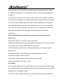
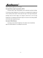
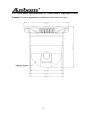
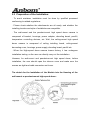
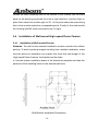
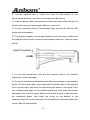
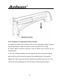
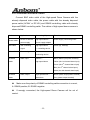
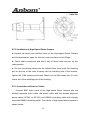
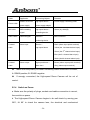
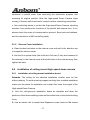
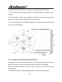
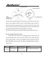
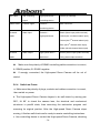
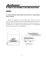
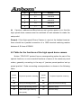
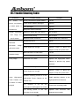
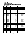
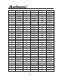
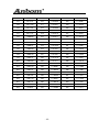
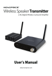
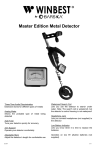
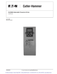
Table of the Contents I. Introduction………………………………………..……………………………..…………….. 3 II. Technical Data………………………………………………………………………...……….3 III. Characteristics ……………………………………..………………………...……………….8 IV. Description of Functions……………………………………………..…..………………..9 V. Installation and Connection of the Devices…………………….………..………….14 5.1 Outer-shape and Dimension of Wall-mount, Pendant- mount and Ceiling-mount High-speed Dome Camera ……………………………..………………………..……………14 5.2 Installation Style and Ancillary Components..…………………….…………..……......16 5.3 Preparation for the Installation…………………………………………..………….…....17 5.4 Installation of Wall-mount High Speed Dome Camera…………………….….………..18 5.5 Installation of Pendant-mount High Speed Dome Camera……………….……….…...24 5.6 Installation of Ceiling-mount High Speed Dome Camera…………………..…...…….. 27 5.7 Connection and Installation of Alarm………………………………………….………….31 VI. Setup of the functions of the High-speed Dome Camera…………….………34 6.1 Set up Address, Baud Rate and Protocol for High Speed Dome Camera……….…..34 6.2 Table for the Functions of the High Speed Dome Camera …………………….………36 6.3 Set up and Preview Preset Positions…………………………………..……….………..39 6.4 Set up and run Tour Groups……………………………………………………….………40 6.5 Set up and start Left & Right Scan…………………………………...………….………..42 6.6 Start 360°endless scan…………………………………………….……..……….………43 6.7 Stop Left & Right scan and 360°Scan……………………………………………….…...44 6.8 Open and close the menu of camera module………………………………..……….….44 6.9 Set up, Activate and Exit the Default Position function………………………………….44 6.10 Open and close Fog Dispersing function…………………………………..…………...45 VII. Trouble Shooting…………………………………………………………………...……..46 VIII. Address coding corresponding table……………………………………..………..47 Important Safeguards 1. During the course of transportation and storage, the product should be avoided from incorrect operations such as heavy pressing, strong vibration, soaking etc, which may cause damage to the unit. 2. The product is designed for Wall-mount, Pendant-mount or Ceiling-mount installation, so it can not be installed upside-down. And the module should be handled properly so as not to bring about mechanical problems affecting the integrative functions of it. The vitreous cover of the dome is complicated optical component, so do not touch it with bare hand(s). Otherwise, the cover might be scraped, and image quality affected. 3. To ensure that the image from the High-speed Dome Camera is crisp, the vitreous cover of the Speed Dome should be cleaned periodically. When cleaning, please be cautious, please note that only the outer ring can be held, please don’t directly touch the vitreous cover, because the acid sweat from your hands may corrode the plating of the vitreous cover, and any scrape on the vitreous cover may cause the image blur and infuence the quality of the image. Please use dry cloth which is soft enough or other substitute to wipe the outer or inner surface. If it is serious dirty, netral cleanser can be used to clean the vitreous cover. 4. Do not let any foreign objects or liquid infiltrate into the unit, which may damage the unit. 5. Please follow all electrical standards for safety when the unit is being connected and please adopt the particular power supply which is provided with the unit. The product’s RS-485 and video signal adopt TVS-class lightning damage preventing technology, which can effectively prevent such pulse signal damage caused by lightning under 500W or electric surge. RS-485 and video signal should be kept enough distance from high voltage equipments and cables when they are in transmission, and necessary steps should be taken to prevent lightning -1- damage or power surge. 6. No matter the unit is runing or not, the camera should never be aimed at the sun or object with extremely bright light. Otherwise, the camera’s CCD might be permanently damaged. 7. There are no parts inside the unit which can be repaired by the users themselves. When mechanical problems arise, do not be in a haste to do any repairing, please refer to the User’s Manual to find the trouble. If causes can not be located, please refer servicing to qualified professionals. All servicing must be done by authorized personnel. -2- I. Introduction Adopting latest technological achievements and cutting-edge manufacturing techniques, the JG-QG900A Series High Speed Dome Camera is created with many years of accumulated experience. Equiped with a high performance DSP camera with zooming lens, integrating built-in Pan/tilt and digital decoder, it represents the future trend of hi-tech monitoring products. The unit is capable of rapid positioning, consecutively tracing and scanning, which realizes real all-directional monitoring. The unit can automatically adapt to ambient brightness and object distance. Its digital control and elegantly simple design maximally reduces the connection between differnent parts in the system, which improves the reliability of the system and facilitate the installation and maintenance. Driven by a stepper electric motar, the unit runs smoothly, reacts quickly and locates positions accurately. With varieties of high-performances, the high speed dome camera can be applied in every walk of life to monitor moving objects in large areas, such as monitoring smart buildings, bank, city streets, power departments, airports, bus/railway stations etc. II. Technical Data 2.1 Technical Data of the High Speed Dome Camera Power supply Ambient temperature DC14~30V(2A), AC18~30V (2A) Indoor: (0ºC~40ºC) outdoor: (-40℃~60℃) ≤95% non-condensing Relative humidity Power consumption 20W Communication system RS485 bus Baudrate of communication 1200/2400/4800/ 9600bps Pan speed (manual control) 0.5º-200º/s (64 ranges) Highest Pan speed 350º/s -3- Pan movement 360ºendless Tilt movement 90º Automatic flip Automatic 180ºflip when vertical 90º Speed Auto-control as per The dome can automatically adjust the running speed following the change of the focal length. the changing of focal length Left & right Scan and 360º Scan Scanning speed Yes High/Medium/Low 3 levels optional Preset position number 128 Tour Groups 4 Preset position number in each tour 16 preset positions Dwell time at each position of tour 1~255 s adjustable Alarm 4 Channels in, 1 Channel out Default Position function Yes Fog Dispersion function Yes Address range of the speed dome 1-255 Fan Automatically start when the temperature is above 50℃ Heater Automatically start when temperature is below 5℃ 2.2 Camera Module Data (Built-in Canon Camera Module) Type Canon 22× color / Canon 22× color (day and night) Synchronization Internal sync/external sync Scan 2:1 interlace Resolution 480TVL Min. illumination 0.07Lux Iris auto/manual Focus auto/manual Lens zoom ratio 22×optical zoom, 16× electronic zoom Focal length 3.9~85.8mm Effective angle Wide:47º/tele:2º -4- BLC Manual/Auto White balance Auto AGC Auto System of signal NTSC/PAL >50dB S/N Video Signal output 1.0±0.2Vpp 2.3 Camera Module Data (Built-in SONY Camera Module) Type SONY 18× color / SONY 18× color (day and night) Synchronization Internal sync/external sync Scan 2:1 interlace Resolution 480 TVL Illumination 0.7Lux/0.001Lux Iris auto/manual Focus auto/manual Lens zoom ratio 18× optical zoom, 12× electronic zoom Focal length 4.1/73.8mm Effective angle Wide:48º/tele:2.7º BLC Manual/auto White Balance Auto AGC Auto System of signal NTSC/PAL >50dB S/N Signal output 1.0±0.2Vpp -5- 2.4 Camera Module Data (Built-in HITACHI Camera Module) Type HITACHI 23 color /HITACHI 23 color (day and night) Synchronization Internal sync/external sync Scan 2:1 interlace Resolution 480TVL for color/ 600TVL for B&W Min. Illumination 0.2Lux for color /0.02Lux for B&W Iris auto/manual Focus auto/manual Lens zoom ratio 23×optical zoom, 10× electronic zoom Focal length 3.6~98mm Effective angle Wide: 55º/tele:2.4º BLC Manual/auto White Balance Auto AGC Auto System of signal NTSC/PAL >50dB S/N Signal output 1.0±0.2Vpp 2.5 Camera Module Data (Built-in LG Camera Module) Type LG 27× color / LG 27× color (day and night) Synchronization Internal sync/external sync Scan 2:1 interlace Resolution 480TVL Min. Illumination 0.3Lux/0. 01Lux Iris auto/manual Focus auto/manual -6- Lens zoom ratio 27×optical zoom, 10× electronic zoom Focal length 3.6~98mm Effective angle Wide:55º/tele:2.4º BLC Manual/auto White balance Auto AGC Auto System of signal NTSC/PAL >48dB S/N Signal output 1.0±0.2Vpp 2.6 Camera Module Data (Built-in CNB Camera Module) Type CNB 22× Color (day and night) Synchronization Internal sync/external sync Scan 2:1 interlace Resolution Min. illumination 480TVL 1.0Lux(Color)/0.01Lux(Black and White) Iris auto/manual Focus auto/manual Lens zoom ratio 22×optical zoom, 10× electronic zoom Focal length 3.9~85.8mm BLC Manual/Auto White balance Auto AGC Auto System of signal NTSC/PAL >50dB S/N Video Signal output 1.0±0.2Vpp -7- III. Characteristics Adopting multi-functional high-performance DSP design with stable performance Integrated design with compact structure and high reliability Precise electric motor drive ensuring smooth running and agile reaction The internally saved data will not lose within a short period of time (1 year) since power off In-built module programme which can automatically identify 5 brands of cameras including LG, SONY, HITACHI, CANON, CNB. Other camera programmes can also be added as per the requirement of the customers. 128 preset positions for random storage and accurate locating 4 tour groups, 16 preset positions can be included in each tour group Support Left & Right scan and 360°scan function, Low, Medium and High 3-levels speeds optional The unit has a default position 4 channels alarm in, 1 channel alarm out Pan 360°consecutive movement, no blind area for the monitoring Tilt 90°, auto flip at the bottom, which ensures consecutive monitoring Automatically adjusting movement speed according to lens zoom ratio Automatic Iris, Focus and White Balance Manual Fog-dispersing Function is realized. -8- IV. Description of Functions 1. Trace the Target The users can control the movement of the camera by operating the joystick of the keyboard so that they can trace the moving object or change the monitoring area. The angle of view or the size of the image of the object can be changed through adjusting the focal length. In the default Auto-focus, Auto Iris state, following the movement of the camera, the lens will quickly adjust itself to get clear image according to the change of the object. 2.Automatic Adjustment of Focal Length/Movement Speed When the focus is long and in the mode of manual adjustment, due to the high sensitivity of the High-speed Dome Camera, even the slightest movement of the joystick would make the image move quickly, which causes image losses. Based on human design, the dome can automatically adjust the horizontal and vertical moving speed of the pan/tilt according to the current focal-length, which makes the manual target-tracing operation much easier. 3.Automatic Flip In the process of operating the joystick to trace and monitor, if the user move the lens to the bottom(vertical) then continues pressing the joystick, the lens will automatically flip 180ºhorizontally, then the user can still control it to move upwards till 90°, which enables the user to directly observe the situation on the back side, thus tilt 180°consecutive monitoring can be -9- realized. 4. Set up and Preview Preset Positions The preset position function works in this way: the High-speed Dome Camera stores the data of the pan/tilt angles and lens focal-length in current state; when needed, preview these data, then move the pan/tilt and the camera to the corresponding position. The user can quickly and conveniently preview the preset position with the controlling keyboard. The High-speed Dome Camera supports 128 preset positions. 5. Automatic Tours The automatic tour function is a built-in function of the High-speed dome camera. Through beforehand programming, the user can arrange the preset positions into the automatic tour in the desired order, then, the user can use such equipment as controlling keyboard to make the High-speed dome camera automatically move as per the order of the preset positions set in the tour with stipulated time intervals. ● Automatic tour among preset positions can be realized through grouping together the preset positions into the tour. ● The tour order is programmable. The staying time at each preset position can be set up. ● Sixteen preset positions can be stored in one tour. Altogether 4 tours can be set up with the speed dome. 6. Automatic Scanning Left/right limiting positions can be set up through controlling keyboard, - 10 - and the camera can automatically scan horizontally between the left limiting position and the right limiting position, at the preset speed. 7. Alarm Function User can set important position as alarm point. Once there is alarm signal coming into the unit from external-connected sensor, the unit will immediately turn the lens to the alarm point, at the same time output alarm signal through the Alarm-output terminal. 8. Default Position Function The unit supports default position function. The user can set up default position for a key monitoring area according to actual conditions. If not operated after 10 minutes, the High-speed Dome Camera will automatically monitor the default position. 9. Camera Lens Control Users can adjust the Focal-length through controlling the keyboard to get panoramic view or close view that they desire. Focal Length Control Users can adjust the Focal-length through controlling the keyboard to get panoramic view or close view that they desire. Focus Control The system takes auto-focus as the default. While moving, the camera can automatically focus on the center of the object view to get clear image. Under special circumstances, the user can manually adjust the focus to achieve desired image effect. - 11 - ● Manual focus can be realized through controlling the keyboard or matrix. For details, please refer to the operation manual of the controlling keyboard or matrix. ● In the state of manual focus, the user can control focal–length to make the lens focus on the object. If the High-speed Dome Camera is set up to resume auto-focus upon joystick operation, when there is operating on the joystick, the High-speed Dome Camera will automatically focus. If a period of time is set up for auto-focus resuming, once there is no controlling order received, after the period of time, the High-speed Dome Camera will resume auto-focus. Under the following circumstances, the camera can not carry out auto-focus: ● When the object is not in the center of the view. ● When simultaneously observe a far object and a near one, clarity for both of the images can not be guaranteed at the same time. ● When observing objects with extreme brightness, such as neon lights, spotlight, etc ● When the object is behind the glass with water drops or dust ● When the object moves very fast ● When the object is large-sized and drab, such as wall ● When the object is too dark or fuzzy Iris Control ● The system takes auto-iris as the default. The iris can automatically sense the change of the environmental light and make quick adjustment, so that the brightness of the image is stable. ● The user can manually adjust the iris through controlling the keyboard to - 12 - obtain desired brightness for the image. Automatic Back Light Compensation (BLC) Automatic Back Light Compensation can be realized via district dividing. In extremely bright background, the camera can compensate the brightness of the relatively dark objects, while adjust the light of the bright background, avoiding that the whole image is too bright to watch due to the too high brightness of the background while the object is too dark to be distinguished, so that the clear image can be got. Automatic White Balance According to the ambient brightness, the camera can automatically adjust the White Balance to re-display the real color. - 13 - V. Setup, Installation and Connection There are three types of installation for high speed dome cameras, the dimensions are shown below: 5.1 Outer-shape and Dimension of Wall-mount, Pendantmount and Ceiling-mount High-speed Dome Camera 5.1.1 Outer-shape and Dimension of Wall-mount and Pendant-mount High-speed Dome Camera - 14 - 5.1.2 Outer-shape and Dimension of Ceiling-mount High-speed Dome Camera (The outer appearance is defferent from the former two) - 15 - 5.2 Installation Style and Ancillary Components Products Bracket Installation Style Wall-mount Cable (with connector) Wall bracket Power Cable 1pc Bracket with the length Video cable 1pc of 20cm or 40 cm 485 cable 1pc Pendant-mount High Speed Dome 5-strands Camera cable 1pc (Alarm input) Ceiling-mount No bracket 2-strands cable 1pc (Alarm output) Remarks: 1. The connection must be carried out by qualified personnel conforming to local regulations. 2. For connection details, please refer to the silk-screen printing indications and installation instructions on the PCB board. 3. The vitreous cover of the High-speed Dome Camera is complicated optical component, so do not touch it with bare hand(s). Otherwise, the cover might be scraped, and image quality affected. 4. To ensure the clarity of images, please clean the vitreous cover regularly. Be careful when cleaning it. You can only hold the outer ring of the vitreous cover. Do not touch it with bare hand(s), for acid sweat left may erode the surface plating of the vitreous cover, or hard things may scrape the vitreous cover leading to fuzzy image and, hence, affecting image quality. Please use adequately soft dry cloth or other substitutes to clean the inner and outer surfaces. If the vitreous cover is extremely dirty, it may be cleaned with mild detergent. - 16 - 5.3 Preparation of the Installation: · To avoid mistakes, installation must be done by qualified personnel conforming to related regulations. · Please check whether the attachments are all ready, and whether the installing location and style of installation are compatible. · The wall-mount and the pendant-mount high speed dome camera is composed of bracket, housings, power adaptor, decoding board, pan/tilt, temperature controlling devices, etc. Well, the ceiling-mount high speed dome camera is composed of ceiling installing board, ceiling-mount decorating cover, housings, power supply, decoding board, pan/tilt etc. · When the High-speed dome camera leaves factory, it has undergone installation testing, so the user can directly carry out the installation. However, for wall-mount and pendant-mount high speed dome, before installation, the user should open the vitreous cover and make sure the screws are tight and cable connectors not loose. The sketch for the Installation of the Module into the Housing of the wall-mount or pendant-mount high speed dome: - 17 - Locate the three installing slots at the bottom of the module into the three pegs on the housing peg-board (be sure in right direction), and lock them in place then swivel the module right for 20°, to the point where the screw-fixing hole in the module meets the corresponding stud. Finally, fix the module with the housing with M3 screw and make sure it is tight. 5.4 5.4.1 Installation of Wall-mount High-speed Dome Camera Installation of Wall-mount Bracket Remarks: The wall for the selected installation location must be firm without peeling. To avoid quivering images resulting from unstable installation, make sure the place for installation can sustain five times the total weight of the High-speed Dome Camera, the bracket and the base. A. Use the bottom installation board of the bracket as template and draw the positions of the installing holes on the desired wall locus; Wall Bracket Installation Dimensions - 18 - B. Use an electrical drill to make four holes for M6 screws on the above-drawn positions, and drive in the expansion M6 screws; C. Push the power cable, communication cable and video cable through the bracket tube, leaving long enough cables for connection; D. Fix the installation board of the bracket firmly on the wall with four M6 screw nuts and washers. E. Put the power adaptor into the wall bracket and pin the power adaptor with the adaptor pinning board, lest the power adaptor slides out. (See the figure below) F. Fix the high speed dome with the wall bracket. (refer to the detailed explanation in the next page) G. Put up the wall bracket assembled with high speed dome on the ancillary hooks. Pull the power cable, video cable and controlling cable out through the wire out-going hole, and direct the dotted-line part shown in the figure to the two corresponding pegs on the installed peg-board, then push the bracket downward until it locks in place. Make sure the wall bracket is well fixed with the installation board, then direct the screw on the bracket to the corresponding hole on the lower part of the installation board and tighten the screw. (See the figure below) - 19 - 5.4.2 Installation of High Speed Dome Camera a. Unpack the carton and carefully take out the High-speed Dome Camera and its attachments, open the vitreous cover and take out the fillings. b. Check cable connectors and see if any of them loose and set up the coding switch. c. Put the connecting cables into the bracket tube, then push the installing port on the top of the outer housing into the installing hole of the bracket, tighten the 3 M6 screws and fix well. Make sure the M6 screws just fit in the screw slot of the installing port of the housing. (See the picture below) - 20 - - 21 - 5.4.3 Connection of Exterior Cables Connect BNC video outlet of the High-speed Dome Camera with the already disposed video cable, the power cable with the already disposed power cable (AC24V or DC14V) and RS485 controlling cable with already disposed RS485 controlling cable. The cables of high speed dome camera is shown below: Cable Application Connecting Objects Remarks AC24V or DC14V high speed dome--- Power supply connecting outlet power supply power supply adaptor 485 controlling high speed dome signal --- controlling device Camera signal Camera--- Power cable 485 cable Video Cable Green (A), white(B) BNC connector monitoring device 5-strand Alarm input cable Detctor--- Black (Alarm input public terminal) high speed dome Yellow (the 1st channel alarm input) Green (the 2nd channel alarm input) Blue (the 3rd channel alarm input) White (the 4th channel alarm input) 2-strand Alarm output cable ◆ High speed dome--- Brown (alarm output public terminal) alarm horn Grey (alarm output terminal) Make sure the polarity of RS485 controlling cable connection is correct, A: RS485 positive, B: RS485 negative. ◆ If wrongly connected, the High-speed Dome Camera will be out of control. - 22 - The detailed connection as the sketch below: 5.4.4 a Switching on Power Make sure the polarity of plugs, sockets and cables connection is correct, then switch on power b The High-speed Dome Camera begins to do the self-check by moving pan 360°, tilt 90° to check the camera lens, the electrical and mechanical structures in pan/tilt state, then executing the restoration program and resuming its original position. After the High-speed Dome Camera stops moving, it finishes self-check and is ready to receive controlling instructions c Use controlling device to control the High-speed Dome Camera, checking whether it can perform the functions of the pan/tilt and camera lens. If not, please check the setup of communication protocol, Baud rate and address, and the connection of 485 controlling cable. - 23 - 5.4.5 a Vitreous Cover Installation Clean the dust and stain on the vitreous cover with soft cloth, attention not to scrape the vitreous cover; b Aim the four special bolts (the bolts don’t fall even if they are loosened to the extreme) in the vitreous cover at the bolts holes in the outer housing, then tighten the bolts. 5.5 Installation of Pendant-mount High Speed Dome 5.5.1 Installation of Pendant-mount Bracket Remarks: The ceiling for the selected installation location must be firm without peeling. To avoid quivering images resulting from unstable installation, make sure the place for installation can sustain five times the total weight of the High-speed Dome Camera, the bracket and the base. A Use the bracket as template and draw the positions of the installing holes on the desired ceiling locus; B Use an electric drill to make three holes for M6 screws on the above-drawn positions, and drive in the special M6 screws; C Push the power cable, communication cable and video cable through the bracket tube, leaving long enough cables for connection; D Fix the bracket firmly on the ceiling with three M6 screw nuts and washers. - 24 - 5.5.2 Installation of High Speed Dome Camera a. Unpack the carton and carefully take out the High-speed Dome Camera and its attachments, open the vitreous cover and take out the fillings. b. Check cable connectors and see if any of them loose and set up the coding switch. c. Put the connecting cables into the bracket tube, then push the installing port on the top of the outer housing into the installing hole of the bracket, tighten the 3 M6 screws and fix well. Make sure the M6 screws just fit in the screw slot of the installing port of the housing. 5.5.3 Connection of Exterior Cables Connect BNC video outlet of the High-speed Dome Camera with the already disposed video cable, the power cable with the already disposed power cable (AC24V or DC14V) and RS485 controlling cable with already disposed RS485 controlling cable. The cables of high speed dome camera is shown below: - 25 - Cable Application Connecting Objects Remarks AC24V or DC14V high speed dome--- Power supply connecting outlet power supply power supply adaptor 485 controlling high speed dome--- signal controlling device Camera signal Camera--- Power cable 485 cable Video Cable Green (A), white(B) BNC connector monitoring device 5-strand Alarm input cable Detctor--- Black (Alarm input public terminal) high speed dome Yellow (the 1st channel alarm input) Green (the 2nd channel alarm input) Blue (the 3rd channel alarm input) White (the 4th channel alarm input) 2-strand Alarm output cable ◆ High speed dome--- Brown (alarm output public terminal) alarm horn Grey (alarm output terminal) Make sure the polarity of RS485 controlling cable connection is correct, A: RS485 positive, B: RS485 negative. ◆ If wrongly connected, the High-speed Dome Camera will be out of control. 5.5.4 Switch on Power a. Make sure the polarity of plugs, sockets and cables connection is correct, then switch on power b. The High-speed Dome Camera begins to do self-check by moving pan 360°, tilt 90° to check the camera lens, the electrical and mechanical - 26 - structures in pan/tilt state, then executing the restoration program and resuming its original position. After the High-speed Dome Camera stops moving, it finishes self-check and is ready to receive controlling instructions c. Use controlling device to control the High-speed Dome Camera, checking whether it can perform the functions of the pan/tilt and camera lens. If not, please check the setup of communication protocol, Baud rate and address, and the connection of 485 controlling cable. 5.5.5 Vitreous Cover Installation a. Clean the dust and stain on the vitreous cover with soft cloth, attention not to scrape the vitreous cover; b. Aim the four special bolts (the bolts don’t fall even if they are loosened to the extreme) in the vitreous cover at the bolts holes in the outer housing, then tighten the bolts. 5.6 5.6.1 Installation of ceiling-mount high speed dome camera Installation of ceiling-mount installation board Remarks: The ceiling for the selected installation location must be firm without peeling. To avoid quivering images resulting from unstable installation, make sure the place for installation can sustain five times the weight of the High-speed Dome Camera. A. Use the ceiling-mount installation board as template and draw the positions of the three installing holes and the cable hole on the desired ceiling locus; B. Use an electric drill to make three Expansion screw holes for M6 screws - 27 - on the above-drawn positions, and drive in the Expansion M6 screws; C. Use an electric drill to make a cable hole with the diameter of 20mm on the ceiling. D. Push the power cable, communication cable and video cable through the cable hole, leaving long enough cables for connection; E. Fix the ceiling-mount installation board firmly on the ceiling with three M6 screw nuts and washers. 5.6.2 Installation of High Speed Dome Camera A. Unpack the carton and carefully take out the High-speed Dome Camera and its attachments, open the vitreous cover and take out the fillings. B. Check cable connectors and see if any of them loose and set up the coding switch. C. Install the module of the high speed dome. (See the picture below) - 28 - Locate the three installing slots at the bottom of the module into the three pegs on the installation board (be sure in right direction), and lock them in place then swivel the module right for 20°, to the point where the screw -fixing hole in the module meets the corresponding stud. Finally, fix the module with the installation board with M3 screw and make sure it is tight. D. Install the decorating cover with the installation board, tighten the screw. 5.6.3 Connection of Exterior Cables Connect BNC video outlet of the High-speed Dome Camera with the already disposed video cable, the power cable with the already disposed power cable (AC24V or DC14V) and RS485 controlling cable with already disposed RS485 controlling cable. The cables of high speed dome camera is shown below: Cable Application Connecting Objects Remarks AC24V or DC14V high speed dome--- Power supply connecting outlet power supply power supply adaptor Power cable - 29 - 485 cable Video Cable 485 controlling high speed dome--- signal controlling device Camera signal Camera--- Green (A), white(B) BNC connector monitoring device 5-strand Alarm input cable Detector--- Black (Alarm input public terminal) high speed dome Yellow (the 1st channel alarm input) Green (the 2nd channel alarm input) Blue (the 3rd channel alarm input) White (the 4th channel alarm input) 2-strand Alarm output cable ◆ High speed dome--- Brown (alarm output public terminal) alarm horn Grey (alarm output terminal) Make sure the polarity of RS485 controlling cable connection is correct, A: RS485 positive, B: RS485 negative. ◆ If wrongly connected, the High-speed Dome Camera will be out of control. 5.6.4 Switch on Power a. Make sure the polarity of plugs, sockets and cables connection is correct, then switch on power b. The High-speed Dome Camera begins to do self-check by moving pan 360°, tilt 90° to check the camera lens, the electrical and mechanical structures in pan/tilt state, then executing the restoration program and resuming its original position. After the High-speed Dome Camera stops moving, it finishes self-check and is ready to receive controlling instructions c. Use controlling device to control the High-speed Dome Camera, checking - 30 - whether it can perform the functions of the pan/tilt and camera lens. If not, please check the setup of communication protocol, Baud rate and address, and the connection of 485 controlling cable. 5.7 Connection and installation of alarm Connect the alarm cables according to the sketch below. Once distinguishing the alarm signal coming in, the speed dome will immediately act as per the process set before, it will start the camera, display the image of the alarm zone on the monitor, adjust the speed dome to the alarm point, and monitor the preset position, record what happens at the alarm zone as soon as possible. Connection of the alarm cables as the sketch below: Attention: a. Alarm input must be ON/OFF input signal, any other types of input signal(such as power voltage etc) is possible to damage the unit. When there are alarm signals from multi channels, the unit will respond to them one by one, the interval is 2 seconds. b. Once there is alarm signal coming in, the unit will not respond to “Scan” , “Cruising” etc functions. Manual operation is needed to restore “Scan” , “Cruising” etc functions. c. No matter the alarm funtion is opened or closed, alarm output always responds. For example, if the alarm function of the unit is not open, when the unit distinguishes alarm signal, the unit will not be adjusted to corresponding preset position, but the alarm output still responds. d. The operation method for alarm fuction is: through previewing the No. 147(117) “preset position” to open alarm function, throuh previewing No. - 31 - 148(118) “preset position” to close alarm function. e. For the input terminals which are not connected with detectors, 2.2KΩ risistor must be connected, otherwise the speed dome will thinks that there is alarm signal coming in, thus the alarm output is always on. Alarm output connection sketch Connection sketch for Alarm input with Usual-closed detector - 32 - Connection sketch for Alarm input with Usual-open detector - 33 - VI. Setup of the functions of the High Speed Dome Camera 6.1 Setup Address, Baud Rate and Protocol for High Speed Dome Camera Before the installation of the High-speed Dome Camera, you must confirm the protocol and Baud rate of the controlling system as well as the address code of the high speed dome camera, then, set up the switches in the speed dome to conform to the controlling system. The corresponding switches setup is shown in the following figure: - 34 - 6.1.1 Set up Communication Protocol of the High Speed Dome Camera The DIP-1 and DIP-2 of SW2 on the PCB board is for communication protocol setup. Please refer to the following table: NO. 2 1 PROTOCOL 1 0 0 PELCO_D 2 0 1 PELCO_P 3 1 0 JCO 4 1 1 PELCO_D1 If the controlling device could only support the preset position numbers below 128, please use PELCO_D1 controlling protocol. 6.1.2 Set up the Address of the High Speed Dome Camera Before actual using, the address of the High-speed dome camera should be set up. The switches(1-8) of SW1 on the PCB board is used to set address of the High-speed Dome Camera from 1 to 255. The coding switches from DIP-1 to DIP-8 are equivalent to a 8-bit binary figure. The state “ON” of each bit means “1” while”OFF”means”0”. Corresponding state of coding switches and address is shown in the appendix table. 6.1.3 Set up Baud Rate of Communication DIP-3 and DIP-4 of SW 2 on the PCB board is used to set up Baudrate of communication, the default setup is 4800BPS. Following table shows states of coding switches and cosrresponding Baudrate. - 35 - ◆ No. 43 Baudrate 1 00 1200 BPS 2 01 2400 BPS 3 10 4800 BPS 4 11 9600 BPS If protocol, address and Baud rate are set up when power is on, then the high speed dome camera must be switched off and restarted to make the setup valid. Remark: If the High-speed Dome Camera is used at the farthest terminal, there should be a parallel connection of a 120Ω terminal matching resistor between A, B lines of RS485. 6.2 Table for the functions of the high speed dome camera Notice: “PELCO-D” protocol has no corresponding orders for part of the special functions, so we converted functions of some of the commonly-used orders, generally converting in the way of “preview preset position/ set up preset position”. Order converting correspondence is shown in the following table: Preview Preview “preset “preset Keyboard operation meaning Keyboard operation meaning position” position” No. No. 130 Set up left limiting position 138 Stop Pan/tilt auto-scanning 131 Set up right limiting position 140 Start tour setup 132 Start Left & right scanning 141 Exit tour setup (low speed) - 36 - 133 Start Left & right scanning 142 Start running a tour 147 Open Alarm Function 148 Close Alarm Function 162 Activate default position function 163 Close default position function 164 Set up default position function 165 Open the fog dispersing function 166 Close the fog dispersing function (medium speed) 134 Start Left & right scanning (high speed) 135 Start Pan/tilt 360ºscanning (low speed) 136 Start Pan/tilt 360ºscanning (medium speed) 137 Start Pan/tilt 360ºscanning (high speed) 150 High speed dome camera position restoration 145 Enter menu of the camera module 146 Exit menu of the camera module If preset position numbers larger than 128 could not be previewed on the controlling device, please choose PELCO-D1 protocol, functions operation table as below: Preview Preview “preset “preset Keyboard operation meaning Keyboard operation meaning position” position” No. No. 100 Set up left limiting position 108 Stop Pan/tilt auto-scanning 101 Set up right limiting position 110 Start tour setup - 37 - 102 Start Left & right scanning (low 111 Exit tour setup 112 Start running a tour 117 Open Alarm Function 118 Close Alarm Function 122 Activate default position function 123 Close default position function 124 Set up default position function speed) 103 Start Left & right scanning (medium speed) 104 Start Left & right scanning (high speed) 105 Start Pan/tilt 360ºscanning (low speed) 106 Start Pan/tilt 360ºscanning (medium speed) 107 Start Pan/tilt 360ºscanning (high speed) 99 High speed dome camera position restoration 95 Enter menu of the camera module 125 Open the fog dispersing function 96 Exit menu of the camera module 126 Close the fog dispersing function Intelligent control and all of its functions can be realized through the keyboard’s control over High-speed Dome Camera. Because different controlling system interfaces may differ in operation, operation details are subject to the related manufacturer’s manuals. Under certain circumstances of special requirements and operations, please refer to dealers for necessary information. - 38 - 6.3 Set up and Preview Preset Positions The function of preset positions works in this way: the High-speed Dome Camera saves the current pan/tilt and zooming ratio parameters in number order (1-128), quickly previews those parameters when needed, and adjust the dome to the corresponding positions. Users can use such devices as controlling keyboard to save and preview preset positions quickly and conveniently. The High-speed Dome Camera can support 128 preset positions. 6.3.1 Set up Preset Positions After adjusting the pan/tilt of the High-speed Dome Camera to desired state (including position, lens, focus and iris) through the keyboard, enter the number representing the preset position and LED displays the entered preset position number. Press the “PRESET” key, then LED resumes to previous displaying state again, now you have set up the preset position successfully. Example: Set up preset position No.1 a. Use the joystick to move the High-speed Dome Camera to the desired position and adjust the camera lens. b. Enter “1” c. Press the “PRESET” key ◆ Manual focus approach can be adopted to set up preset positions for distant objects, that is, after adusting the lens to focus on distant place, control the keys “FOCUS+”and “FOCUS-”on the controlling keyboard to set up optimal focal image storage to avoid fuzzy images resulting from the interference of other distant objects. - 39 - 6.3.2 Preview Preset Positions The function enables the High-speed Dome Camera to quickly return to the preset position. Enter the number(1~128) key for preset position number which you need to preview, and LED displays the preset position number. Then, press the “PREVIEW” key. The High-speed Dome Camera will return to the preset position. e.g. Preview the No.1 preset position a. Enter “1” b. Press “PREVIEW” key 6.4 Setup and run tour groups The tour group function is to group some preset positions together, if the user wants to preview these preset positions, with only one external order, the High-speed Dome Camera will automatically preview the preset positions in the group one by one. The dwelling time at each preset position can be set within 1-255 seconds. Up to 16 preset positions can be saved in each tour group. And at most 4 tour groups can be set up. The operation is as below: A. In the keyboard initial state, enter number “140”(110) and press the “PREVIEW” key to enter the tour setup. B. After entering the setup, add preset position number to the tour. Enter the first desired preset position number and press the “PREVIEW” key, and the first preset position is successfully added. Then goes the second one. Enter the second desired preset position number and press the “PREVIEW” key, and the second preset position is successfully added. More preset positions can be added in the same way. - 40 - C. After all the required preset positions having been added in the tour, enter the number “141”(111) on the keyboard and press the “PREVIEW” key to exit the tour setup. D. Start Running a Tour: In the keyboard initial state, enter number “142”(112) and press the “PREVIEW” key to start running the preset tour. Example: Set up the tour order to be 1→2→5→3→4→6 (please set up preset positions before tour setup) 1. Preview “preset position” 140(110) to enter tour setup (Enter number “140”(110) and press the “PREVIEW” key) 2. Preview preset position 1 to set up the first tour position (Enter number “1” and press the “PREVIEW” key) 3. Preview preset position 2 to set up the second tour position (Enter number “2” and press the “PREVIEW” key) 4. Preview preset position 5 to set up the third tour position (Enter number “5” and press the “PREVIEW” key) 5. Preview preset position 3 to set up the fourth tour position (Enter number “3”and press the “PREVIEW” key) 6. Preview preset position 4 to set up the fifth tour position (Enter number “4”and press the “PREVIEW” key) 7. Preview preset position 6 to set up the sixth tour position (Enter number “6”and press the “PREVIEW” key) 8. Preview “preset position” 141(111) to exit tour setup (Enter number “141”(111) and press the “PREVIEW” key) 9. Preview “preset position” 142(112) to start running the tour, and the High-speed Dome Camera runs the tour and begins to scan in the order - 41 - of 1→2→5→3→4→6. If other devices are used to control the High-speed Dome Camera, due to the protocol limitation, some special functions of the High-speed Dome Camera may be not operational. 6.5 Setup and start Left & Right scan The speed dome camera has Left/Right scanning function. The user can set up the left and right limiting positions for the required left&right scanning area. When running the left&right scan, the unit will scan forwards and backwards between the left and right limiting positions consecutively. 6.5.1 Set up Left & Right limiting positions The user can freely set a beginning point as the Left Limiting Position, an end point as the Right Limiting Position(Attention: If the beginning point is the same as the end point, the speed dome will scan 360°endlessly). Meanwhile, the unit will automatically record the zooming times of the lens at the beginning point and take this data as the constant zooming times of the lens when scanning, also, the unit will record the vertical angle of the beginning point and take this angle as the constant vertical angle when scanning. The operation of setting up Left & right limiting position is as below: 1. Set up the Left Limiting Position: Operate the joystick towards left, adjust the image to the desired postion, then: 2. A. Input 130(100) B. Press PREVIEW key Set up the Right Limiting Position: After the Left Limiting position is set up well, operate the joystick towards right, adjust the image to the desired postion, then: - 42 - A. Input 131(101) B. Press PREVIEW key After setting up well, operate as below to run the scan. 6.5.2 Start Left & Right scan: To start Left & Right scan means that the user use an external order to start the scan and to make the speed dome scan between two limiting positions, so that the user can monitor the corresponding district. Three kinds of speed are optional: 132(102) for low speed, 133(103) for medium speed, 134(104) for high speed. The user can operate on the keyboard, the operation is as below: Operation through previewing function code: a. Input 132(102) b. Press PREVIEW key Then the speed dome will scan between the two positions with low speed. The setup method for other speeds are the same. 6.6 Start 360°endless scan The Speed Dome can carry out 360°scan function. So that all-direction scanning and monitoring effect is realized. Three kinds of speed are optional: 135 for low speed, 136 for medium speed, 137 for high speed. The user can operate on the keyboard, the operation is as below: a. Input 135 b. Press PREVIEW key Then the speed dome will carry out 360°endless scanning. The setup method for other speeds are the same. - 43 - 6.7 Stop Left & Right scan and 360°scan While the unit is carrying out scanning operation, if you require the unit carry out other operations, you can operate on the keyboard to stop the auto scan. Operation is as below: a. Input 138(108) b. Press PREVIEW key The Auto Scan can also be stopped by any operation on the joystick of the keyboard. 6.8 Open and close the menu of camera module The unit has a function as “setting up the parameters of the Camera Module”. Users can open and close the menu of the camera by previewing 145 and 146 “preset positions”. After entering the menu, users can set up the camera conveniently. The operation is as below: 1. Open the menu of the camera a. Input 145(95) b. Press PREVIEW key. 2. Close the menu of the camera a. Input 146(96) b. Press PREVIEW key. Attention: If the camera module doesn’t have menu function, this function with the unit is unavailable. 6.9 Setup, Activate and Exit the Default Position function The unit has a default position. The user can set up default position for a key monitoring area according to actual conditions. If not operated after 5 - 44 - minutes, the high speed dome camera will automatically turn to the default position and monitor. 1. Set up the Default Position Move the High-speed Dome Camera to a key monitoring area through controlling keyboard, then enter number “164”(124) from the keyboard and press the “PREVIEW” key, then the setup is successful. 2. Activate and Exit the Default Position function The user can activate or exit the function of default position through the keyboard. Enter number “162”(122) and press the “PREVIEW” key, the function is activated. Enter number “163”(123) and press the “PREVIEW” key, the function is exited. 6.10 Open and close fog-dispersion function. Due to the influence of the climatic condition, there may be fog on the vitreous cover of the high speed dome, if it influences the image of the camera, the user can disperse the fog through the Fog-dispersion function, so that the user can see clear image. (Working principle: When the fog-dispersion function is open, the heater and the fan will begin to work simutaneously, the temperature inside the speed dome will increase thus the fog will disappear.) The operation is as below: 1. 2. Open the fog-dispersion function: a. Input 165 (125) b. Press PREVIEW key Close the fog-dispersion function: a. Input 166 (126) b. Press PREVIEW key - 45 - VII. Trouble Shooting Table Problems Possible causes remedies Wrong connection of power cables Correct picture, no indicator Power supply adaptor damaged Replace on when power is Fuse damaged Replace switched on. Bad power cable connection Correct Normal Address or Baud rate setup wrong Set up again Protocol setup wrong Set up again RS485 bus bad connection Check RS485 bus connection Mechanical failure Repair Camera inclined Reinstall Power supply not enough Replace, better to place the No action, and no self-check image but out of control Abnormal self-check image with motor noise adaptor nearby the speed dome Bad connection of video cable Correct Power supply not enough Replace At Manual focus state Operate the High-speed Dome Unstable image Fuzzy image Camera or preview any preset positions Vitreous cover dirty Clean the vitreous cover Replace, better to place the Power supply not enough adaptor nearby the speed dome Whether matching resistor is in the Some Install matching resistor in the High-speed High-speed Dome Camera at the Dome Camera out High-speed Dome Camera farthest end of control or control The distance is too far, the delayed Thicken the controlling cable attenuation of 485 signal is too much The driving power of converter is not enough - 46 - the 485 Replace with converter separate power supply with VIII. Correspondence of Address and Coding Switches (SW1: DIP1-DIP8) NO 87654321 NO 87654321 NO 87654321 1 00000001 32 00100000 63 00111111 2 00000010 33 00100001 64 01000000 3 00000011 34 00100010 65 01000001 4 00000100 35 00100011 66 01000010 5 00000101 36 00100100 67 01000011 6 00000110 37 00100101 68 01000100 7 00000111 38 00100110 69 01000101 8 00001000 39 00100111 70 01000110 9 00001001 40 00101000 71 01000111 10 00001010 41 00101001 72 01001000 11 00001011 42 00101010 73 01001001 12 00001100 43 00101011 74 01001010 13 00001101 44 00101100 75 14 00001110 45 00101101 76 01001100 15 00001111 46 00101110 77 01001101 16 00010000 47 00101111 78 01001110 17 00010001 48 00110000 79 01001111 18 00010010 49 00110001 80 01010000 19 00010011 50 00110010 81 01010001 20 00010100 51 00110011 82 01010010 21 00010101 52 00110100 83 01010011 22 00010110 53 00110101 84 01010100 23 00010111 54 00110110 85 01010101 24 00011000 55 00110111 86 01010110 25 00011001 56 00111000 87 01010111 26 00011010 57 00111001 88 01011000 27 00011011 58 00111010 89 01011001 28 00011100 59 00111011 90 01011010 29 00011101 60 00111100 91 01011011 30 00011110 61 00111101 92 01011100 31 00011111 62 00111110 93 01011101 - 47 - 01001011 NO 87654321 NO 87654321 NO 87654321 94 01011110 125 01111101 156 10011100 95 01011111 126 01111110 157 10011101 96 01100000 127 01111111 158 10011110 97 01100001 128 10000000 159 10011111 98 01100010 129 10000001 160 10100000 99 01100011 130 10000010 161 10100001 100 01100100 131 10000011 162 10100010 101 01100101 132 10000100 163 10100011 102 01100110 133 10000101 164 10100100 103 01100111 134 10000110 165 10100101 104 01101000 135 10000111 166 10100110 105 01101001 136 10001000 167 10100111 106 01101010 137 10001001 168 10101000 107 01101011 138 10001010 169 10101001 108 01101100 139 10001011 170 10101010 109 01101101 140 10001100 171 10101011 110 01101110 141 10001101 172 10101100 111 01101111 142 10001110 173 10101101 112 01110000 143 10001111 174 10101110 113 01110001 144 10010000 175 10101111 114 01110010 145 10010001 176 10110000 115 01110011 146 10010010 177 10110001 116 01110100 147 10010011 178 10110010 117 01110101 148 10010100 179 10110011 118 01110110 149 10010101 180 10110100 119 01110111 150 10010110 181 10110101 120 01111000 151 10010111 182 10110110 121 01111001 152 10011000 183 10110111 122 01111010 153 10011001 184 10111000 123 01111011 154 10011010 185 10111001 124 01111100 155 10011011 186 10111010 - 48 - NO 87654321 NO 87654321 NO 87654321 187 10111011 210 11010010 233 11101001 188 10111100 211 11010011 234 11101010 189 10111101 212 11010100 235 11101011 190 10111110 213 11010101 236 11101100 191 10111111 214 11010110 237 11101101 192 11000000 215 11010111 238 11101110 193 11000001 216 11011000 239 11101111 194 11000010 217 11011001 240 11110000 195 11000011 218 11011010 241 11110001 196 11000100 219 11011011 242 11110010 197 11000101 220 11011100 243 11110011 198 11000110 221 11011101 244 11110100 199 11000111 222 11011110 245 11110101 200 11001000 223 11011111 246 11110110 201 11001001 224 11100000 247 11110111 202 11001010 225 11100001 248 11111000 203 11001011 226 11100010 249 11111001 204 11001100 227 11100011 250 11111010 205 11001101 228 11100100 251 11111011 206 11001110 229 11100101 252 11111100 207 11001111 230 11100110 253 11111101 208 11010000 231 11100111 254 11111110 209 11010001 232 11101000 255 11111111 - 49 -