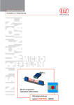
Download Instruction Manual eddyNCDT SGS 4701 (PDF, 384 - Micro
Transcript
Instruction Manual eddyNCDT SGS 4701 EMU04(10x) EMU04(12x) EMU04(11x) EMU04(13x) EMU04(14x) EMU04(16x) EMU04(15x) EMU04(17x) Digital Eddy-Current Measuring System for Spindle Growth System MICRO-EPSILON MESSTECHNIK GmbH & Co. KG Königbacher Strasse 15 94496 Ortenburg / Germany Tel. +49 (0) 8542 / 168-0 Fax +49 (0) 8542 / 168-90 e-mail [email protected] www.micro-epsilon.com Certified acc. to DIN EN ISO 9001: 2008 Contents 1.Safety......................................................................................................................................... 5 1.1 Symbols Used.................................................................................................................................................. 5 1.2Warnings........................................................................................................................................................... 5 1.3 Notes on CE Identification................................................................................................................................ 6 1.4 Proper Use........................................................................................................................................................ 6 1.5 Proper Environment.......................................................................................................................................... 7 2. System Description................................................................................................................... 8 2.1 Measuring Principle.......................................................................................................................................... 8 2.2 Structure of the Measuring System.................................................................................................................. 9 2.3Glossary.......................................................................................................................................................... 10 Technical Data................................................................................................................................................ 11 2.4 3.Delivery ................................................................................................................................... 12 3.1Unpacking ...................................................................................................................................................... 12 3.2Storage .......................................................................................................................................................... 12 4. Installation and Assembly....................................................................................................... 13 4.1Precautions..................................................................................................................................................... 13 4.2Sensor............................................................................................................................................................. 13 4.3 Sensor Cable.................................................................................................................................................. 15 4.4Controller........................................................................................................................................................ 17 4.5 Connecting the Measuring System................................................................................................................ 18 5.Operation................................................................................................................................. 19 6.Warranty................................................................................................................................... 19 7. Service, Repair ....................................................................................................................... 20 8. Decommissioning, Disposal .................................................................................................. 20 eddyNCDT SGS 4701 Appendix A 1 Clamping Flange Controller................................................................................................... 21 A 2 Tool Sensor Cable................................................................................................................... 22 A 3 Optional Accessories.............................................................................................................. 22 A 4 Notes for Electrostatic Discharge.......................................................................................... 23 eddyNCDT SGS 4701 Safety 1. Safety The handling of the system assumes knowledge of the instruction manual. 1.1 Symbols Used The following symbols are used in the instruction manual. Indicates a hazardous situation which, if not avoided, may result in minor or moderate injuries. Indicates a situation which, if not avoided, may lead to property damage. Indicates a user action. i 1.2 Indicates a user tip. Warnings Connect the power supply and the display / output device in accordance with the safety regulations for electrical equipment. >> Danger of injury >> Damage to or destruction of the controller and/or sensor The power supply must not exceed the specified limits. >> Damage to or destruction of the controller and/or sensor Avoid shock and vibration to the sensor and controller. >> Damage to or destruction of the controller and/or sensor Protect the sensor cable against damage >> Failure of the measuring device eddyNCDT SGS 4701 Page 5 Safety 1.3 Notes on CE Identification The following applies to the measuring system eddyNCDT series SGS 4701: -- EU directive 2004/108/EC -- EU directive 2011/65/EC, “RoHS” category 9 Products which carry the CE mark satisfy the requirements of the quoted EU directives and the standards (EN) listed therein. The EC declaration of conformity is kept available according to EC regulation, article 10 by the authorities responsible at MICRO-EPSILON Messtechnik GmbH & Co. KG Königbacher Straße 15 94496 Ortenburg / Germany The measuring system is designed for the use in industry and satisfies the requirements. 1.4 Proper Use -- The measuring system eddyNCDT series SGS 4701 is designed for use in industrial areas. It is used for displacement, distance and movement measurement for temperature detection position measuring of parts or machine components -- The measuring system may only be operated within the limits specified in the technical data, see Chap. 2.4. -- Use the measuring system in such a way that in case of malfunctions or failure personnel or machinery are not endangered. -- Take additional precautions for safety and damage prevention for safety-related applications. eddyNCDT SGS 4701 Page 6 Safety 1.5 Proper Environment -- Protection class: -- Operating temperature: Sensor/ sensor cable Controller -- Storage temperature: -- Humidity: -- Ambient pressure: eddyNCDT SGS 4701 IP 67 (in plugged state) 0 ... +90 °C (+32 ... +194 °F) +10 ... +70 °C (+50 ... +158 °F) 0 ... +70 °C (+32 ... +158 °F) 5 - 95 % (non-condensing) Atmospheric pressure Page 7 System Description 2. System Description 2.1 Measuring Principle The eddyNCDT series SGS 4701 (Non-Contacting Displacement Transducers) measuring system operates on the basis of eddy currents without making physical contact. It is used for measurements on objects consisting of electrically conducting materials which have ferromagnetic or non-ferromagnetic properties. High frequency alternating currents flow through a coil cast in a sensor housing. The electromagnetic field from the coil induces eddy currents in the electrically conducting target, causing the alternating current resistance of the coil to change. This change of impedance delivers an electrical signal proportional to the distance of the target from the sensor. The eddyNCDT SGS 4701 conditions the sensor signals user-fairly at a frequency response of 2,000 Hz. Thus a so-called spindle monitoring is also still possible at numbers of revolutions up to 120,000 rpm. The spindle growth itself can be detected at even higher numbers of revolutions. Ferromagnetic metals have different zones of magnetization, which therefore dampen the eddy current field of the sensor to varying degrees. Non-ferromagnetic metals do not have these same material characteristics and so are perfectly suited to axial runout measurements and spindle monitoring. Fig. 1 Controller eddyNCDT SGS 4701 eddyNCDT SGS 4701 In order to achieve highly accurate measurements, it is imperatively necessary that one (or more) sample(s) item under test is / are provided by the customer. Page 8 System Description 2.2 Structure of the Measuring System The eddyNCDT series SGS 4701 is developed for recording the thermal and mechanical extension of highspeed milling spindles. This enables the active compensation of the axial spindle extension via CNC machine tool. The SGS 4701 consists of a sensor, a sensor cable and a controller, factory calibrated for ferromagnetic respectively non-ferromagnetic measurement objects. Miniature sensors enable it to be installed directly in the spindle, where the measurements take place, typically on the labyrinth-ring of the spindle. As well as measuring linear extension, the temperature of the sensor is also detected and output. The compact controller can be installed on the spindle housing via a flange or directly in the spindle. Fig. 2 Typical installation with measurement on the labyrinth ring Due to its compact size, the measurement technology (paired electronics and sensor) is fully integrated into the spindle head. Compared to its predecessor model, the eddyNCDT SGS 4311, interchangeability between sensor and electronics is unnecessary and no longer possible. eddyNCDT SGS 4701 Page 9 System Description 2.3 Glossary SMR Start of measuring range. Minimum distance between sensor front and target MMRMidrange EMR End of measuring range (start of measuring range + measuring range) Maximum distance between sensor front and target MR Measuring range U [V] U [V] 9.5 Signal 9.5 5 ea r .a Lin Displacement 0.5 0 100 600 µm 0.5 0 % it ar e Lin y± Temp. 0 90 °C Target Sensor Measuring range SMR eddyNCDT SGS 4701 Page 10 System Description 2.4 Technical Data Sensor system Measuring range Offset Linearity Resolution 1) Frequency response Target Minimum target diameter Operating temperature Temperature stability Temperature compensation range Sensor Controller Sensor Controller Sensor Controller Supply voltage Analog out Protection class Dimensions Sensor cable eddyNCDT SGS 4701 Displacement Temperature Sensor / controller EMU04(10x) EMU04(12x) Diameter Length Min. bending radius Coating SGS4701 500 µm (option 250 µm 2)) 100 µm (option 50 µm 2)) ±2 µm 0.5 µm 2000 Hz ferromagnetic / non-ferromagnetic 6 mm (option 3.5 mm 2)) 0 ... +90 °C (+32 ... +194 °F) +10 ... +70 °C (+50 ... +158 °F) ±150 ppm FSO/°C (MMR) ±500 ppm FSO/°C (MMR) +10 ... +80 °C (+50 ... +176 °F) +10 ... +70 °C (+50 ... +158 °F) 12 ... 32 VDC 0.5 - 9.5 V � 100 - 600 µm (option 50 - 300 µm 2)) 0.5 - 9.5 V (� 0 ... +90 °C) IP 67 (in plugged state) 12 x 10 x 4.5 mm³ 10 x 4 x 4 mm³ Ø 1.13 mm 1000 mm (400 - 1500 mm on request) 12 mm FEP Page 11 Delivery Sensor system Shock SGS4701 DIN EN 60068-2-27 (50 g, 6 ms, 3 cycles in each direction) Vibration DIN EN 60068-2-6 (20 g, 10 - 3000 Hz) FSO = Full Scale Output; MMR = Midrange 1) Static at midrange (MMR) 2) For OEM modifications: sensor with 250 μm measuring range and 50 μm SMR distance 3. Delivery 3.1 Unpacking 1 SGS 4701(xxx) 1 Test report 1 Instruction manual Check for completeness and shipping damage immediately after unpacking. In case of damage or missing parts, please contact the manufacturer or supplier. You will find optional accessories in appendix, see Chap. A 3. 3.2 Storage Storage temperature: 0 ... +70 °C (+32 ... +158 °F) Humidity: eddyNCDT SGS 4701 5 - 95 % (non-condensing) Page 12 Installation and Assembly Installation and Assembly 4.1 Precautions No sharp or heavy objects should be allowed to affect the cable sheath of the sensor cable, the power supply cable and the output cable. Check all plug-in connections for firm seating before starting operation. Sensor Sensor design 1 Sensor design 2 EMU04(12x) EMU04(10x) 0 2.5 (.099) ) 0 -0 002 (0.008 4 edges 0 0.2 -0.05 x 45° 4 -0 03 4 0-0 03 0 (.16 -0 0011 ) ø 2. (.1 d 5 ia) EMU04(15x) EMU04(14x) 12 (.47) 1.5±0.05 (.06 ±0.002) EMU04(17x) ø 1.13 (.04 dia) EMU04(11x) 1.5±0.05 (.06±0.002) Potting Sensor coil EMU04(16x) 0.3x45° (0.012x45°) EMU04(13x) 6 (.24) 1.75 (.07) 4.2 10 -0.2 (.39 008) Destruction of the controller by electrostatic discharge via the sensor. Please observe the notes regarding electrostatic discharge, see Chap. A 4. 4. 4.5 ±0.05 (0.18 ±0.05) -0 005 10 -0 027 0002 (0.39 -0 ) -0 001 Fig. 3 Dimensional drawing sensor, dimensions in mm (inches), not to scale eddyNCDT SGS 4701 Page 13 Installation and Assembly Start of measuring range For each sensor a minimum distance to the target must be maintained. This avoids a measurement uncertainty due to the sensor pressing on the target and mechanical damage to the sensor/ target. Fig. 4 Start of measuring range (SMR), the smallest distance between sensor face and target Sensor Target Measuring range SMR The minimum measuring area must have a diameter of 6 mm or greater for an eddy-current sensor. Optional sensors are available with a minimum area diameter of 3.5 mm. If you underrun the minimum measuring area nor reproducibly measurements are possible. Sensor Measuring area ø ≥ 6 mm Measuring area Fig. 5 Minimum measuring area for eddy-current sensor eddyNCDT SGS 4701 Page 14 Installation and Assembly 4.3 Sensor Cable Operating temperature -40 ... +90 °C Inner conductor silver-coated annealed copper wire Mating life 20 cycles Dielectric core FEP Fire resistance VM-1 Outer conductor silver-coated annealed copper wire Cable retention 12.74 N Jacket FEP 1.44 ± 0.2 (.06 ± .008) Minimum bending radius 12 mm 3 ± 0.2 (.12 ± .008) Cable, -length [mm] 40 50 EMU04(100)-C080 5.3 ± 0.3 (.21 ± .02) 80 100 130 x EMU04(101)-C150 x EMU04(102)-C100 x EMU04(103)-C050 EMU04(104)-C040 x x EMU04(105)-C130 EMU04(120)-C080 150 x x EMU04(121)-C100 EMU04(122)-C150 x x Fig. 6 Dimensional drawing sensor cable, dimensions in mm (inches), not to scale Lay the sensor cable in such a way that no sharp-edged or heavy objects can affect the cable sheath. Do not kink the cable. Details to the sensor cable are listed in the appendix, see Chap. A 4. Sensor Bending radius: R ≥ 12 mm Controller Fig. 7 Minimum bending radius for sensor cable eddyNCDT SGS 4701 Page 15 Installation and Assembly Do not shorten the sensor cable. Loss of functionality. Removing the connector is only permitted behind the plug-sided crimp when using the solder connections. Connect the sensor cable to the controller, see Fig. 8. Solder connection i Plug connection Open the cable gland on the controller. Avoid a strong cable bending. Bend up the green cable seal easily and insert the sensor cable. Push the sensor cap over the sensor cable. Run the sensor cable through the cable gland. Shield Signal Solder the sensor cable to the connection board. Connect the sensor cable to the female connector. Close the cable gland. Push the sensor cap onto the controller housing until it snaps in place. Fig. 8 Connection sensor cable eddyNCDT SGS 4701 Page 16 Installation and Assembly 4.4 Controller 94.2 ±0.1 (3.71 ± .004) ø 12 -0.1 (.47 dia. -.004) (ca. 8) (approx. .31) 102.2 ±0.5 (4.02 ± .02) M12x1 WS 8 Fig. 9 Dimensional drawing of controller, dimensions in mm (inches), not to scale The controller is mounted laminar with a circumferential clamping on housing or with an optional clamping flange. eddyNCDT SGS 4701 Page 17 Installation and Assembly 4.5 Connecting the Measuring System Provide the power supply for the controller. i Connect the 8-pin M12 connector to the controller with a power supply 24 VDC. Optional accessories: PC4701-10 power supply and output cable, 10 m long, with 8-pin. female connector respectively with free ends. Connect the measurement signal display respectively control unit to the controller. PIN Comment Color PC4701-10 1 Ground white 2 12 ... 32 VDC brown 3 Displacement signal (0.5 ... +9.5 V) at 100 ... 600 μm green 4 Temperature signal (0.5 ... +9.5 V) at 0 ... +90 °C yellow 5 NC gray 6, 7 internally assigned pink, blue 8 NC red Screen Housing - 5 4 6 8 7 1 3 2 8-pin. male connector controller, view on pin side Fig. 10 Pin assignment for signal output eddyNCDT SGS 4701 Page 18 Operation 5. Operation The system is ready for operation. There are no adjustments which must be done by the user. MICRO-EPSILON recommends to let the system warm up for about 30 minutes. 6. Warranty All components of the device have been checked and tested for perfect function in the factory. In the unlikely event that errors should occur despite our thorough quality control, this should be reported immediately to MICRO-EPSILON. The warranty period lasts 12 months following the day of shipment. Defective parts, except wear parts, will be repaired or replaced free of charge within this period if you return the device free of cost to MICRO-EPSILON. This warranty does not apply to damage resulting from abuse of the equipment and devices, from forceful handling or installation of the devices or from repair or modifications performed by third parties. No other claims, except as warranted, are accepted. The terms of the purchasing contract apply in full. MICRO-EPSILON will specifically not be responsible for eventual consequential damages. MICRO-EPSILON always strives to supply the customers with the finest and most advanced equipment. Development and refinement is therefore performed continuously and the right to design changes without prior notice is accordingly reserved. For translations in other languages, the data and statements in the German language operation manual are to be taken as authoritative. eddyNCDT SGS 4701 Page 19 Service, Repair 7. Service, Repair Please send us the effected parts for repair or exchange. MICRO-EPSILON MESSTECHNIK GmbH & Co. KG Königbacher Straße 15 94496 Ortenburg / Germany In the case of faults the whole measuring system must be sent back to: Tel. +49 (0) 8542/ 168-0 In the event of a defect on the sensor, controller or the sensor cable: Fax +49 (0) 8542 / 168-90 [email protected] www.micro-epsilon.com 8. Decommissioning, Disposal Disconnect the power supply and output cable on the controller. Disconnect the sensor cable between sensor and controller. Do the disposal according to the legal regulations (see directive 2002/96/EC). eddyNCDT SGS 4701 Page 20 Appendix| Clamping Flange Controller Appendix Clamping Flange Controller 20 (.79) 20 (.79) ø2 15 (.59) . (.1 7 1d ia. ) 15 (.59) 2.8 (.11) 12.8 (.50) A 1 Dimensions in mm (inches), not to scale eddyNCDT SGS 4701 Seite 21 Appendix| Tool Sensor Cable Tool Sensor Cable 1.5 (.06) 6 (.24) 3.2 (.13) 2.7 (1.1) 0.6 (.02) 3.6 (.14) 4.7 (.19) A 2 15 (.59) 47 (1.85) 1.5 (.06) 50 (1.97) Dimensions in mm (inches), not to scale You will find details for the tool to the sensor cable miniature connector under: http://www.radiall.com/rf-coaxial-connectors/mml-extraction-tool-h2-0-h2-5.html A 3 Optional Accessories PC4701-10 eddyNCDT SGS 4701 Power supply and output cable, 10 m long, with 8-pin. female connector respectively with open ends Seite 22 Appendix| Notes for Electrostatic Discharge A 4 Notes for Electrostatic Discharge Electrostatic discharge (ESD) may lead to the destruction of the controller when -- connecting the sensor cable to the open controller, -- handling the sensor. The working practices listed below reduce and avoid any electrostatic discharge: -- Wear a grounding bracelet that is conductive connected to an earthing point. -- The table surface should be conductive and connected to the earthing point. -- Wear appropriate shoes, ESD working clothes on the upper part of the body and the arms in order to avoid any static charging. Further literature for the prevention of electrostatic phenomenon: -- EN 61340-5-1 Protection of electronic components against electrostatic phenomenon - General requirements -- EN 61340-5-2 Protection of electronic components against electrostatic phenomenon - User manual -- VDE publications 71 Electrostatics, reasons, effects, protective measures eddyNCDT SGS 4701 Seite 23 MICRO-EPSILON MESSTECHNIK GmbH & Co. KG Königbacher Str. 15 · 94496 Ortenburg / Germany Tel. +49 (0) 8542 / 168-0 · Fax +49 (0) 8542 / 168-90 [email protected] · www.micro-epsilon.com X9751318-A031115HDR MICRO-EPSILON MESSTECHNIK *X9751318-A03*


