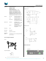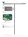
1
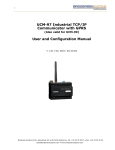
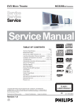
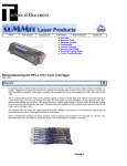
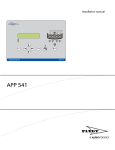
RTU32E
RTU32E Series Powerful Compact Utility RTU
Data Sheet
Doc: 40347 v1.03 / October 14th, 2014
RTU32E Data Sheet
INTRODUCTION
The Brodersen RTU32E controller series is based on a 32-bit
platform that provides the RTU/PLC with power and leading
edge functionality. It is provided with an open and
adjustable platform with both the power and functionality
required to control the most demanding industrial
applications.
Full remote management with configuration,
programming and flexible distribution of all levels
of software from and to RTUs in remote locations.
VERSIONS / ORDERING CODES
Hardware basic version
Order code: BRE-64IO/231B0131.D1
Fully equipped with a powerful IEC61131 PLC, web server
configuration and real time clock with millisecond
resolution, it provides you with all the advantages the
combination of a very fast PLC and RTU can give you.
Driver runtime license
The RTU32E is supplied in a robust metal anodized
enclosure and can be used with the wide range of Brodersen
I/O expansion modules.
RTU32E are delivered with a range of standard drivers that
includes full Modbus Suite, IEC60870 Suite and RTU
Distributed Binding protocol.
Ethernet and TCP/IP are the basic communication and data
environments; however, serial communication interfaces
like RS232 and USB also allow the RTU32E to interface to
various devices within a network hierarchy.
For additional drivers a runtime driver license has to be
ordered separately.
FEATURES
64 channels of on-board IO
32x digital inputs / counter inputs
16x relay outputs
12x analog inputs
4x analog outputs
Full IEC61131 (IL, LD, STL, FB, SFC.)
Several Communication Protocols Supported;
Full Modbus suite.
IEC60870-5-101 Master/Slave
IEC60870-5-104 Client/Server
IEC60870-5-103 Master
IEC61850 Client
IEC61850 Server with GOOSE.
DNP3 Master/Slave
WITS-DNP3 Slave (UKWITS)
EtherNet/IP Scanner
DF1 Master
ProfiNET Client
RTU Distributed Binding Protocol
SMNP agent for network monitoring,
alarming etc.
Gateway / data concentrator functions.
Dual Ethernet and 4x COM Interfaces.
Support for over 1000 local I/Os and +60000
distributed I/O
Robust Design for Industrial Applications.
The available driver licenses are;
Order code
DL-IEC61850S-RL
DL-IEC61850C-RL
DL-SNMP-RL
DL-PROFINETC-RL
DL-DNP3S-RL
DL-DNP3M-RL
DL-DNP3SWITS-RL
DL-118.C37C-RL
DL-DLMS.1-RL
DL-DF1M-RL
DL-ETHIPC-RL
Description
IEC61850 Server driver with GOOSE/MMS
IEC61850 Client driver
SNMP Agent driver
ProfiNET Client driver
DNP3 Slave Serial/Ethernet driver
DNP3 Master Serial/Ethernet driver
DNP3 WITS Slave Serial/Ethernet driver
118.C37 Phasor Client Driver
DLMS/IEC62056 Master driver
AB DF1 Master driver
EtherNet/IP Scanner driver
Our range of drivers is developed all the time - ask if your
driver is missing or have special requirements. Special
versions can be delivered as an option. Contact us for more
details.
Document no. 40347 103 RTU32E Data Sheet_14-10-2014.docx
Brodersen A/S, Islevdalvej 187, DK-2610 Roedovre, Denmark , Tel: +45 45 35 26 27, Fax: +45 45 35 26 29, Email: [email protected]
2
RTU32E Data Sheet
PLC Runtime Details ........................................................ 9
CONTENTS
INTRODUCTION................................................................... 2
PLC Runtime performance: ......................................... 9
FEATURES............................................................................ 2
Power Supply ................................................................... 9
VERSIONS / ORDERING CODES ........................................... 2
General ............................................................................ 9
Hardware basic version .................................................. 2
Circuit Configuration (Digital) ............................................ 10
Driver runtime license .................................................... 2
Circuit Configuration (Analogue) ....................................... 10
Wiring details RTU32E ................................................. 4
Interface Overview ............................................................ 10
TECHNICAL DESCRIPTION ................................................... 5
Change analogue input type mA DC to V DC .................. 11
General ........................................................................... 5
Change Battery for NV RAM and System clock ................. 12
Software Basic Setup and Configuration ..................... 5
Software RTU Configuration and Programming .......... 5
Software Communication Drivers ................................ 6
......................................................... 6
I/O Driver ........................................................................ 6
IEC60870-5-101/103/104 ............................................... 6
IEC61850 Client and Server ............................................. 6
DNP3 Master / Slave - Full Suite ..................................... 6
Data Logging ................................................................... 6
Modem Control / Dial-up / Dial-in .................................. 6
Real-Time / Real-Time Clock ........................................... 6
COM communication for NullModem, Radio and
LeasedLine modems ....................................................... 6
3G / GPRS Modem controlled directly by RTU32E ......... 7
Power supply .................................................................. 7
Other Connectivity / Interfaces ...................................... 7
Security ........................................................................... 7
Status and Diagnostic Information ................................. 7
I/O Configuration ............................................................ 7
Integrated I/O options .................................................... 7
I/O Expansion options ..................................................... 7
RTU hardware monitoring .............................................. 7
TECHNICAL SPECIFICATIONS ............................................... 8
Basic 32-Bit CPU System ................................................. 8
Physical Interfaces .......................................................... 8
I/O options ...................................................................... 8
Integrated Digital Inputs (counter inputs) ...................... 8
Integrated Relay Outputs................................................ 8
Integrated Analogue Input.............................................. 8
Integrated Analogue Output ........................................... 9
Software.......................................................................... 9
Document no. 40347 103 RTU32E Data Sheet_14-10-2014.docx
Brodersen A/S, Islevdalvej 187, DK-2610 Roedovre, Denmark , Tel: +45 45 35 26 27, Fax: +45 45 35 26 29, Email: [email protected]
3
RTU32E Data Sheet
Wiring details RTU32E
NOTE: All DI are also working as 32bit counter inputs. 8 x 1kHz and 24 x 100Hz. DI 4-7 in
section DI1 and DI3 are 1kHz counter inputs and rest is 100Hz.
Document no. 40347 103 RTU32E Data Sheet_14-10-2014.docx
Brodersen A/S, Islevdalvej 187, DK-2610 Roedovre, Denmark , Tel: +45 45 35 26 27, Fax: +45 45 35 26 29, Email: [email protected]
4
RTU32E Data Sheet
TECHNICAL DESCRIPTION
General
All the RTU32E software is stored on a removable Compact
Flash card. During start-up, the operating system and
applications are moved to RAM where it is executed. System
configuration settings are stored on the Flash. Retained
variables and buffered events can be stored in non-volatile
RAM.
Using the Ethernet network for primary communication
provides all the advantages of existing TCP/IP networking
communication facilities such as FTP, HTTP, Telnet, SNTP
etc. Fast, reliable and secure communication is the main
topic. Standard networking components (software, routers,
switches, etc.) are available to use with the RTU32E. In
addition, serial ports for interfacing to application specific
protocols (e.g. Modbus, Fieldbus, utility protocols, network
management protocols etc.) are available.
Software Basic Setup and Configuration
The main page contains information about the software
(version, build, type), installed drivers and actual
connection data.
Software RTU Configuration and Programming
The Brodersen WorkSuite fully supports EN/IEC61131 and is
used for creating and compiling PLC runtime projects in the
RTU32E. WorkSuite supports programming languages such
as Structured Text (ST), Function Block (FB), Ladder (LD),
Instruction List (IL) and Sequential Function Chart (SFC). The
RTU32E supports cold restart, hot restart and on-line
changes.
Brodersen WorkSuite is also a powerful tool for complete
system design and programming, providing unique
functions for event based communication. The Global
Binding Editor makes it possible to publish and subscribe
variables in a large network with minimal communication
load. The events are time stamped.
Programming, debugging and upload and download of
application programs can be done remotely via Ethernet or
RS232.
RTU32E main settings are configured via the internal
webpages as on all other kind of networking devices.
Default IP: 192.168.0.1
The main configuration also includes;
LAN network settings (IP, subnet, gateway, DNS
etc.).
Basic PLC mode settings.
Built-in I/O settings/actual configuration
Hardware Overview / Status on I/Os
Modem / VPN Settings
Security
Real time clock settings / SNTP
SNMP agent
Redundancy
Remote secure protocols
HMI
Online status of physical I/O
Document no. 40347 103 RTU32E Data Sheet_14-10-2014.docx
Brodersen A/S, Islevdalvej 187, DK-2610 Roedovre, Denmark , Tel: +45 45 35 26 27, Fax: +45 45 35 26 29, Email: [email protected]
5
RTU32E Data Sheet
Software Communication Drivers
The basic drivers and protocols available for the RTU32E
are:
I/O drivers for integrated I/O and I/O Expansion.
Modbus RTU Master and Slave.
Modbus TCP Client and Server.
Modbus ASCII Master and Slave.
IEC60870-5-101 Master and Slave.
IEC60870-5-103 Master.
IEC60870-5-104 Client and Server.
IEC61850 Client
IEC61850 Server incl. GOOSE
SNMP Agent driver.
PROFI NET Client.
DNP3 Master / Slave Full Suite
DNP3 UK-WITS Slave
EtherNet/IP Scanner
DF1 Master
COMLI Master
DLMS/IEC62056 Master
118.C37 Client
Distributed event based binding etc.
interface to another without compromising the actual value
and original time stamp. Also sharing data queues from
more ports are possible.
Internal I/O and expansion I/O are managed in an
independent database. The I/O database structure is
designed as a multi-accessible database. The database runs
in its own high priority task and provides fast and reliable
I/O communication.
Data Logging
A special data logging function block is available for logging
event based or cyclical data to the flash file system. The data
logging also supports functions for formatted logs directly
exportable to zenon® HMI and SCADA software. Log files
can be downloaded from the RTU32E via FTP.
The PLC runtime includes a flexible variable database that
the user configures with names and data types with no
need for fixed or special mapped registers.
In addition, an API for programmers provides access to the
database from your own C#, C++ or VBA application. It can
also be used as gateway access to the application program.
I/O Driver
The RTU32E I/O can be accessed via variable profiles (each
I/O is directly addressed). I/O diagnostic/status information
is also available. The I/O driver supports up to 32 I/O
expansion modules - and more than 1000 I/Os.
IEC60870-5-101/103/104
Utility protocols IEC60870-5-10x provide full configuration
flexibility of almost any interoperability requirements. The
protocol links are provided as a driver in the application
layer data and protocol structures are generated in
Structured Text (ST). This gives full access to set up any
Interrogation and ASDU required for the application.
In addition, the driver supports advanced features for
gateway functions where, for example, information in the
monitor direction can be moved from one protocol
To simplify and provide fast configuration, a RTU32
IEC60870 Configurator tool is available. See the IEC60870
Configurator for details.
IEC61850 Client and Server
The RTU32E Series support both IEC61850 Client and Server
driver functions. The IEC61850 Client is KEMA certified and
is fully configured in WorkSuite using the SCL file details.
The IEC61850 Server driver is configured based on a SCL file.
The Brodersen WorkSuite includes a SCL file editor where
you can import or create your own SCL file by adding the
Logical Nodes and Data Attributes you want. And after
configuring your Server driver, you can verify it with the
WorkSuite IEC61850 Test Client.
DNP3 Master / Slave - Full Suite
DNP3 Drivers with enhanced support for manual data
handling and diagnostic are supported. DNP3 UK WITS Slave
with full connection manager details is also supported.
Modem Control / Dial-up / Dial-in
Both dial-up and dial-in functions via a PSTN, ISDN or GSM
modem connected to the serial port of the RTU32E are
possible when using the PLC modem function. It can be used
for serial communication e.g. ModbusRTU and IEC60870
serial protocols.
Real-Time / Real-Time Clock
The real-time task is used for the application program
execution. Time stamps and cyclic execution are also based
on the real-time clock. Time stamps are reported in
milliseconds. In order to achieve high time accuracy the
clock has synchronization options with SNTP and a special
clock slave and master function for synchronization from
RTU32E to RTU32E.
COM communication for NullModem, Radio and
LeasedLine modems
The RTU32E has extended data communication features for
communication of ModbusRTU, serial IEC60870-5-101 etc.
over serial modems and converters. The features cover
detailed handshake control with timing of RTS and CTS.
Document no. 40347 103 RTU32E Data Sheet_14-10-2014.docx
Brodersen A/S, Islevdalvej 187, DK-2610 Roedovre, Denmark , Tel: +45 45 35 26 27, Fax: +45 45 35 26 29, Email: [email protected]
6
RTU32E Data Sheet
3G / GPRS Modem controlled directly by RTU32E
The RTU32E support Brodersen 3G/GPRS modems
connected via their USB2 Interface. Webpage configuration
for the 3G/GPRS modems is available to allow automatic
handling of connection to a defined APN. Alternative and
more advanced modem connection handling is supported
via dedicated WorkSuite PLC Functions.
All digital inputs are also working as 32bit counter inputs.
8x are 1kHz and 24x are 100Hz inputs. DI 4-7 in section DI1
and section DI3 are 1kHz counter inputs and the rest is
100Hz. The counters are read and reset using ZI profile I/O
in the PLC application.
I/O Expansion options
Power supply
The RTU32E is available with 10-30 VDC power supply.
Other Connectivity / Interfaces
The two USB ports support mouse, keyboard, Flash disc
storage devices, USB to LAN converters to extend the
number of LAN/Ethernet ports, 3G/GPRS communication
devices etc.
A VGA port for connecting a monitor provides possibility for
work with the RTU directly on the OS user interface and use
local HMI/SCADA via a touch monitor.
Security
Security in access and communication is supported. The
network servers like Webserver and FTP Server are login
and password protected, providing multiple access levels
with dedicated adjustable rights.
The RTU32E Series support PPTP and L2TP VPN Clients and
can be used to login to VPN Servers. VPN is configured via
the Webserver and can be controlled from the PLC logic
Utility drivers including authentication or encryption
features are supported to the extent that is commonly used.
E.g. DNP3 drivers all support Secure Authentication V2.
The RTU32E can be used with all existing UCL type
Brodersen I/O Expansion modules. No programming or
configuration is required the RTU32E supports automatic
I/O configuration of Brodersen I/O Expansion modules.
The LocalBus IO communication bus includes power supply
for I/O Expansion modules. The RTU32E can deliver up to
300mA@12VDC for IO modules. For I/O Module
configuration with current requirements that exceeds
300mA, you must add I/O Additional power supply.
Please see the I/O Expansion selection guide for selecting
your I/O modules.
RTU hardware monitoring
Parameters like power supply voltage level, internal
temperature and battery status are available for monitoring
in the RTU32E logic application. Furthermore memory load
status can be monitored.
Firewall functions can be enabled and adjusted via Remote
Desktop and the Registry Editor.
Status and Diagnostic Information
The RTU32E provides status information on internal
temperature, battery and supply voltage level, memory and
interface board status etc. All status information is available
via a WorkSuite functions in the PLC application.
I/O Configuration
The RTU32E Series is designed to support a wide range of
physical IO configurations primarily obtained via the range
of Brodersen external IO Expansion modules via a LocalBus
RJ45 connector. The RTU32E can also be used with 3rd party
e.g.
distributed I/O via any of the supported drivers
ModbusTCP or DF1.
Integrated I/O options
The RTU32E is available with 64 I/Os - 32DI + 16RO + 12AI +
4AO.
Document no. 40347 103 RTU32E Data Sheet_14-10-2014.docx
Brodersen A/S, Islevdalvej 187, DK-2610 Roedovre, Denmark , Tel: +45 45 35 26 27, Fax: +45 45 35 26 29, Email: [email protected]
7
RTU32E Data Sheet
Integrated Digital Inputs (counter inputs)
TECHNICAL SPECIFICATIONS
Inputs:
Input voltage
activated:
Input voltage
deactivated:
Input current:
Basic 32-Bit CPU System
CPU:
128K L2 cache
BIOS:
AWARD 512KB Flash BIOS
System chipset:
System RAM memory:
One 200-pin SODIMM socket supports
up to 256MB DDR 333 SDRAM.
Standard configuration is 128MB RAM.
Non-volatile RAM:
1MB battery backed RAM.
Disc / SSD:
Input delay:
S 5536.
Min. 128MB removable Compact Flash in
Type I/II socket. Support up to 1GB.
10-30V DC.
Max. 3V DC.
12V DC: Typical 3mA.
24V DC: Typical 6mA.
Typical 1ms.
Isolation:
1kV AC
Indicators:
One LED for each digital input
Count input frequency:
1kHz (8x) and 100Hz (24x).
Integrated Relay Outputs
Relay outputs:
16 potential free SPDT contacts.
Output voltage: Max. 60V DC.
Output current: Max. 2A DC (resistive).
Output delay:
Typical 5ms.
Real time clock: Accuracy: Max. 30ppm, typically 10-12ppm
Resolution: 1 msec
Back-up time: min. 2 years, typical 5 years
(Battery ONLY used if no power is applied).
Lifetime (relay): Min. 100.000 operations at rated load.
Watchdog:
Contact material: Gold overlay silver alloy.
Level 1: Main CPU Watchdog.
Level 2: External watchdog controller.
Isolation
(coils-contacts): 1kV AC 50Hz 1 min (IEC255-5).
Physical Interfaces
Indicators:
One LED for each output (yellow) indicating
active output.
Dual Ethernet:
2 x LAN: Dual Realtek RTL8101L.
COMS:
4 x RS232 (COM1, COM2 full handshake)
USB:
2 x USB 2.0 ports.
Integrated Analogue Input
VGA/LCD:
VGA/LCD interface
Inputs:
PS/2:
Single interface for keyboard and mouse.
I/O Expansion:
RJ45 LocalBus interface for Brodersen I/O
Expansion modules.
I/O options
Expansion I/O:
Expansion I/O is possible via the Brodersen
I/O LocalBus system to all Brodersen I/O
Expansion modules.
Supports up to 32 I/O Expansion modules
of any type.
Integrated I/O:
64IO board integrated;
32 Digital inputs (also works as counter inputs).
16 Relay outputs.
12 Analogue inputs.
4 Analogue outputs.
12 multiplexed analogue channels with
solid state multiplexer.
Input configuration:
Differential (+/ -), flying capacitor type.
Input measuring ranges:
0 - 10V
0 - 5V
-5 - +5V
-10 - +10V
0-2V/0 - 20mA
0.4-2V/4 - 20mA
Selection between these ranges shall be done on Web page and
jumper setting. Default range settings are 4-20mA (with jumpers
set).
Resolution:
14 bit, 0-16383.
Impedance:
Voltage:
Current:
1M Ohm.
100 Ohm ±0,25%.
Document no. 40347 103 RTU32E Data Sheet_14-10-2014.docx
Brodersen A/S, Islevdalvej 187, DK-2610 Roedovre, Denmark , Tel: +45 45 35 26 27, Fax: +45 45 35 26 29, Email: [email protected]
8
RTU32E Data Sheet
Absolute maximum ratings:
Input voltage:
Input current:
Update time:
Accuracy Vout:
25°C:
-10°-60°C:
Linearity:
Better than ± 0,05%.
Isolation:
(output to output): No isolation.
±15V DC.
±30mA DC.
±0.2%
±0.4%
Better than 350 msec.
Measuring accuracy:
25°C: ±0.1% (typically 0.05%).
-10°-55°C: ±0.3% (typically 0.1%).
Software
Linearity:
Better than ± 0.05%.
OS: Windows Embedded Compact 6.
Temperature
stability:
Better than ± 50ppm/°C (typical).
PLC Runtime Details
Common mode
voltage:
Max. ±80V DC.
PLC Runtime performance:
Minimum PLC cycle time: >1 msec.
Typical PLC cycle time: 3-5 msec.
Common mode
rejection ratio: Min. 72dB.
Series mode
rejection:
Maximum variables: 200.000
Scan time internal I/O: Approx. 2-5 msec.
Scan time external I/O: Min. 6 msec. (see User Manual for
details).
Min. 36dB (50-120Hz)
Isolation:
(input to input): 500V.
Power Supply
Integrated Analogue Output
Outputs:
Supply Voltage: 10-30VDC.
4 sourced analogue channels.
Output ranges:
0 - 10V
0 - 5V
-5 - +5V
-10 - +10V
0 - 20mA
4 - 20mA
Selection between these ranges are done in
web page.
Resolution:
14 bit, 0-16383.
Absolute maximum ratings:
Iout:
Vout:
Power
consumption:
Max. 430W and typical 13W Configuration
dependent.
Isolation:
Power supply to electronics: 1500VDC
Max loads:
LocalBus (for supply of I/O Expansion modules)
are 300mA for standard power supply versions.
General
Output voltage:
Load:
Output current:
Output voltage:
Load:
27V DC.
1kOhm
25mA DC.
±15V
1kOhm
Indicators (LEDS):
Power:
System:
Run:
I/O:
Update time:
Better than 100 msec.
A-C:
Batt. error:
Accuracy Iout:
25°C @ 100Ohm: ±0,2%
-10°-60C° @ 100Ohm: ±0,4%
Com 1-4:
Linearity:
Better than ± 0,05%.
DI x and DO x:
Leakage current: Max. 20 µA (typically 5µA)
Temperature
stability:
Better than ± 50ppm/°C, @ 100Ohm.
Indicating power ON.
Indicate system status.
Indicate PLC program status.
Indicate status of integrated
and expansion I/O.
Not used.
Internal battery error.
Indicate Rx/Tx activity on the
COM ports.
Indicate active digital I/O
Ambient temperature:
Storage: -40 - +85°C
Operation: -20 - +60°C.
(Optional: -40 - +70°C - See note 1)
Document no. 40347 103 RTU32E Data Sheet_14-10-2014.docx
Brodersen A/S, Islevdalvej 187, DK-2610 Roedovre, Denmark , Tel: +45 45 35 26 27, Fax: +45 45 35 26 29, Email: [email protected]
9
RTU32E Data Sheet
EMC/LVD:
Climatic:
EN55022:1998 Class A
EN61000-3-2:2000
EN61000-3-3:1995
EN55022:1998 Class A
EN55024:1998 (EN61000-4-2:1995,
EN61000-4-3:1996,EN61000-4-4:1995,
EN61000-4-5:1995, EN61000-4-6:1996,
EN61000-4-8:1993, EN61000-4-11:1994 )
EN 61000-6-2: EMC/ Immunity Industry.
EN 60950: Safety requirements for electrical
equipment for measurement and control.
Dry heat:
Cold:
Damp heat:
Mechanical:
Vibration:
Shock:
Circuit Configuration (Analogue)
Analogue input:
IEC 68-2-2, Test Bd, Temp.
+55°C, Duration 8h.
IEC 68-2-1, Test Ad, Temp.
-10°C, Duration 8h.
IEC 68-2-3, Test Ca, Temp.
40°C, RH 95%, Duration 8h.
IEC 68-2-6, Test Fc
(sinusoidal), Freq. 10-150Hz,
Amp.4g, 5 sweeps in 3
orthogonal axes.
IEC 68-2-27 (half sine), Acc.
15g, Pulse time 11msec.,
3 x 6 shocks.
Analogue Output:
Iout
Protection:
IP20.
Mounting:
Backplane
Housing:
Metal black anodized
Dimensions:
HxWxD:
55x302x192 mm. (incl. mounting bracket and
I/O connectors).
Vout
Circuit Configuration (Digital)
Inputs:
Interface Overview
Right side
Output Relay (SPDT):
Document no. 40347 103 RTU32E Data Sheet_14-10-2014.docx
Brodersen A/S, Islevdalvej 187, DK-2610 Roedovre, Denmark , Tel: +45 45 35 26 27, Fax: +45 45 35 26 29, Email: [email protected]
10
RTU32E Data Sheet
Step 3
Locate jumpers Figure 3
Left Side
Change analogue input type mA DC to V DC
Step 1
Unscrew both screws located as figure 1
Figure 3
Figure 1
Step 2
Take lid off - Figure 2
Step 4
Position jumpers for correct input type V or mA.
Measurement Range for analogue inputs is defined in
Webpage default address 192.168.0.1
See possible input variation at page 8
Jumper designation SW300-SW311
SW 300
SW 301
SW 302
SW 303
SW 304
SW 305
Figure 2
SW 306
SW 307
SW 308
SW 309
SW 310
SW 311
ON Channel 0 = mA
OFF Channel 0 = V
ON Channel 1 = mA
OFF Channel 1 = V
ON Channel 2 = mA
OFF Channel 2 = V
ON Channel 3 = mA
OFF Channel 3 = V
ON Channel 4 = mA
OFF Channel 4 = V
ON Channel 5 = mA
OFF Channel 5 = V
ON Channel 6 = mA
OFF Channel 6 = V
ON Channel 7 = mA
OFF Channel 7 = V
ON Channel 8 = mA
OFF Channel 8 = V
ON Channel 9 = mA
OFF Channel 9 = V
ON Channel 10 = mA
OFF Channel 10 = V
ON Channel 11 = mA
OFF Channel 11 = V
Document no. 40347 103 RTU32E Data Sheet_14-10-2014.docx
Brodersen A/S, Islevdalvej 187, DK-2610 Roedovre, Denmark , Tel: +45 45 35 26 27, Fax: +45 45 35 26 29, Email: [email protected]
11
RTU32E Data Sheet
Change Battery for NV RAM and System clock
Step 1
Unscrew both screws located as figure 4
Figure 4
Step 2
Take lid off Figure 5
Figure 5
Battery type is 3V CR2450N (Renata type)
NOTES:
Note 1:
Extended operating temperature range can be delivered as an
option. Please contact us for details.
Note 2:
This data sheet is subject to change without any prior notice!
Document no. 40347 103 RTU32E Data Sheet_14-10-2014.docx
Brodersen A/S, Islevdalvej 187, DK-2610 Roedovre, Denmark , Tel: +45 45 35 26 27, Fax: +45 45 35 26 29, Email: [email protected]
12