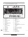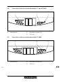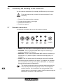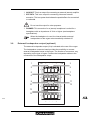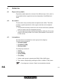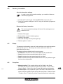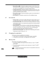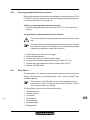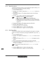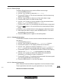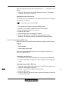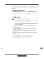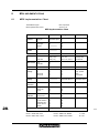
1
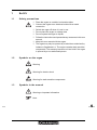
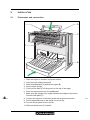
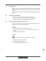
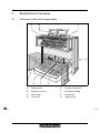
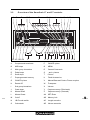
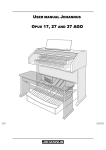
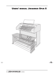
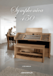
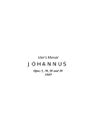
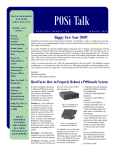
USER MANUAL JOHANNUS SWEELINCK 17, 27 AND 37 AGO /i 2 Manufacturer Johannus Orgelbouw b.v. Address Keplerlaan 2 6716 BS EDE Country The Netherlands Telephone +31 (0)318 63 74 03 Fax +31 (0)318 62 22 38 E-mail [email protected] Website www.johannus.com Version 1.0 Date February 2007 © 2007, Johannus Orgelbouw All rights reserved. Nothing in this publication may be reproduced, stored in a data file or made public in any form or in any way either electronically, mechanically by way of photocopying, recording or in any other way without the prior written permission of Johannus Orgelbouw b.v. TABLE OF CONTENTS 1 SAFETY . . . . . . . . . . . . . . . . . . . . . . . . . . . . . . . . . . . . . . . . . . . . . . . . . . . . 5 1.1 1.2 1.3 2 INSTALLATION . . . . . . . . . . . . . . . . . . . . . . . . . . . . . . . . . . . . . . . . . . . . . 6 2.1 2.2 2.3 2.4 3 Placement and connection . . . . . . . . . . . . . . . . . . . . . . . . . . . . . . . . . . . . . . . 6 Switching on . . . . . . . . . . . . . . . . . . . . . . . . . . . . . . . . . . . . . . . . . . . . . . . . . . 7 Transport and storage . . . . . . . . . . . . . . . . . . . . . . . . . . . . . . . . . . . . . . . . . . . 7 Opening and closing the rolltop cover . . . . . . . . . . . . . . . . . . . . . . . . . . . . . . . 7 DESCRIPTION OF THE ORGAN . . . . . . . . . . . . . . . . . . . . . . . . . . . . . . . . 8 3.1 3.2 3.3 3.4 3.5 3.6 3.7 3.8 4 Safety precautions . . . . . . . . . . . . . . . . . . . . . . . . . . . . . . . . . . . . . . . . . . . . . 5 Symbols on the organ . . . . . . . . . . . . . . . . . . . . . . . . . . . . . . . . . . . . . . . . . . . 5 Symbols in the manual . . . . . . . . . . . . . . . . . . . . . . . . . . . . . . . . . . . . . . . . . . 5 Overview of the main components . . . . . . . . . . . . . . . . . . . . . . . . . . . . . . . . . 8 Overview of the Sweelinck 17 and 27 controls . . . . . . . . . . . . . . . . . . . . . . . . 9 Overview of the Sweelinck 37 controls . . . . . . . . . . . . . . . . . . . . . . . . . . . . . 10 Overview of the toe studs Sweelinck 17 and 27 AGO . . . . . . . . . . . . . . . . . 11 Overview of the toe studs Sweelinck 37 AGO . . . . . . . . . . . . . . . . . . . . . . . 11 Connecting and switching on the accessories . . . . . . . . . . . . . . . . . . . . . . . 12 External connections . . . . . . . . . . . . . . . . . . . . . . . . . . . . . . . . . . . . . . . . . . . 12 External loudspeaker output (optional) . . . . . . . . . . . . . . . . . . . . . . . . . . . . . 13 OPERATION . . . . . . . . . . . . . . . . . . . . . . . . . . . . . . . . . . . . . . . . . . . . . . . 14 4.1 4.2 4.3 4.4 4.5 4.6 4.7 4.8 4.9 4.10 4.11 Expression pedals . . . . . . . . . . . . . . . . . . . . . . . . . . . . . . . . . . . . . . . . . . . . . 14 Acoustics . . . . . . . . . . . . . . . . . . . . . . . . . . . . . . . . . . . . . . . . . . . . . . . . . . . . 14 Intonations . . . . . . . . . . . . . . . . . . . . . . . . . . . . . . . . . . . . . . . . . . . . . . . . . . 14 Factory intonation . . . . . . . . . . . . . . . . . . . . . . . . . . . . . . . . . . . . . . . . . . . . . 15 Stops . . . . . . . . . . . . . . . . . . . . . . . . . . . . . . . . . . . . . . . . . . . . . . . . . . . . . . . 15 Couplers . . . . . . . . . . . . . . . . . . . . . . . . . . . . . . . . . . . . . . . . . . . . . . . . . . . . 15 Accessories . . . . . . . . . . . . . . . . . . . . . . . . . . . . . . . . . . . . . . . . . . . . . . . . . . 16 Changing the registration . . . . . . . . . . . . . . . . . . . . . . . . . . . . . . . . . . . . . . . 16 Memory lock . . . . . . . . . . . . . . . . . . . . . . . . . . . . . . . . . . . . . . . . . . . . . . . . . 16 Preprogrammed memory locations . . . . . . . . . . . . . . . . . . . . . . . . . . . . . . . . 17 Easy Menu . . . . . . . . . . . . . . . . . . . . . . . . . . . . . . . . . . . . . . . . . . . . . . . . . . 17 4.11.1 Capture memory . . . . . . . . . . . . . . . . . . . . . . . . . . . . . . . . . . . . . . . 18 4.11.2 General Volume . . . . . . . . . . . . . . . . . . . . . . . . . . . . . . . . . . . . . . . 19 4.11.3 Transposer . . . . . . . . . . . . . . . . . . . . . . . . . . . . . . . . . . . . . . . . . . . 19 4.11.4 Tuning Mode . . . . . . . . . . . . . . . . . . . . . . . . . . . . . . . . . . . . . . . . . . 20 4.11.5 Temperaments . . . . . . . . . . . . . . . . . . . . . . . . . . . . . . . . . . . . . . . . 20 4.11.6 Keyboard Mode . . . . . . . . . . . . . . . . . . . . . . . . . . . . . . . . . . . . . . . . 21 4.11.7 Display Mode . . . . . . . . . . . . . . . . . . . . . . . . . . . . . . . . . . . . . . . . . . 21 4.11.8 Reset Procedures . . . . . . . . . . . . . . . . . . . . . . . . . . . . . . . . . . . . . . 22 4.11.9 Data Dump Mode . . . . . . . . . . . . . . . . . . . . . . . . . . . . . . . . . . . . . . 22 4.11.10 Demo Songs . . . . . . . . . . . . . . . . . . . . . . . . . . . . . . . . . . . . . . . . . . 23 4.11.11 Standard Intonation . . . . . . . . . . . . . . . . . . . . . . . . . . . . . . . . . . . . . 23 4.11.12 General Crescendo . . . . . . . . . . . . . . . . . . . . . . . . . . . . . . . . . . . . . 23 3 4.11.13 Programming MIDI stops . . . . . . . . . . . . . . . . . . . . . . . . . . . . . . . . . 24 5 MAINTENANCE, PROBLEMS AND WARRANTY . . . . . . . . . . . . . . . . . . 26 5.1 5.2 5.3 6 Maintenance . . . . . . . . . . . . . . . . . . . . . . . . . . . . . . . . . . . . . . . . . . . . . . . . . 26 5.1.1 Cabinet maintenance . . . . . . . . . . . . . . . . . . . . . . . . . . . . . . . . . . . 26 5.1.2 Maintenance of the manuals . . . . . . . . . . . . . . . . . . . . . . . . . . . . . . 26 Problems . . . . . . . . . . . . . . . . . . . . . . . . . . . . . . . . . . . . . . . . . . . . . . . . . . . . 26 5.2.1 Repositioning the pedal . . . . . . . . . . . . . . . . . . . . . . . . . . . . . . . . . . 27 Warranty . . . . . . . . . . . . . . . . . . . . . . . . . . . . . . . . . . . . . . . . . . . . . . . . . . . . 27 MIDI IMPLEMENTATIONS . . . . . . . . . . . . . . . . . . . . . . . . . . . . . . . . . . . . 28 6.1 6.2 MIDI Implementation Chart . . . . . . . . . . . . . . . . . . . . . . . . . . . . . . . . . . . . . . 28 MIDI specifications . . . . . . . . . . . . . . . . . . . . . . . . . . . . . . . . . . . . . . . . . . . . 29 6.2.1 Default basic channels (transmitted/recognized) . . . . . . . . . . . . . . . 29 6.2.2 Basic channel changes (transmitted) . . . . . . . . . . . . . . . . . . . . . . . 29 6.2.3 Control changes (transmitted) . . . . . . . . . . . . . . . . . . . . . . . . . . . . . 29 6.2.4 Control changes (recognized) . . . . . . . . . . . . . . . . . . . . . . . . . . . . . 30 6.2.5 Program changes (transmitted/recognized) . . . . . . . . . . . . . . . . . . 30 6.2.6 System exclusive messages (transmitted/recognized) . . . . . . . . . . 30 INDEX . . . . . . . . . . . . . . . . . . . . . . . . . . . . . . . . . . . . . . . . . . . . . . . . . . . . 33 4 1 SAFETY 1.1 Safety precautions Place the organ on a stable, horizontal surface. Connect the organ to an electrical outlet with an earth connection. Switch the organ off when it is not in use. Do not place the organ in a damp area. Do not expose the organ to liquids. Follow the instructions and precautionary measures in this user manual. Keep this user manual with the organ. The organ may only be opened by a technician authorised by Johannus Orgelbouw b.v. The organ contains static-sensitive components. The warranty becomes null and void if the organ is opened by a non-authorised person. 1.2 Symbols on the organ Warning Warning for electric shock Warning for static-sensitive components 1.3 Symbols in the manual Warning or important information Note 5 2 INSTALLATION 2.1 Placement and connection E D C F A B 1. 2. 3. 4. 5. 6. 7. 6 Place the organ on a stable, horizontal surface. Lean the organ slightly backward. Slide the pedalboard (A) against the organ (B). Set the organ upright. Put the music desk (E) in the groove on the top of the organ. Place the organ bench over the pedalboard. Make sure the voltage of the organ matches the voltage of the mains. See the serial plate (F). 8. Connect the organ to an electrical outlet with an earth connection. 9. Put the appropriate key in the rolltop cover lock (D). 10. Turn the key a quarter turn to the left. 11. Slide the rolltop cover (C) upward. 2.2 Switching on Switch the organ on with the on/off piston at the right, next to the manuals. Wait several seconds. Starting the control functions and the settings takes a little time. The lamps of the on/off and 0 pistons light and the settings appear on the display. 2.3 Transport and storage Pay attention to the following during transport and storage: Remove the music desk and the pedalboard from the organ. Relative humidity within the storage area: 10 to 90%. 2.4 Opening and closing the rolltop cover The organ can be closed with a wooden rolltop cover that has a lock. The rolltop cover lock is behind the music desk. Opening 1. Put the appropriate key in the rolltop cover lock. 2. Turn the key a quarter turn to the left. The lock now rises out of the rolltop. 3. Slide the rolltop cover upward. Closing Never leave the key in the area that can be closed. 1. Slide the rolltop cover downward. 2. Press the rolltop cover lock in. 3. Turn the key a quarter turn to the right. 7 3 DESCRIPTION OF THE ORGAN 3.1 Overview of the main components A B C D H G F E /i 8 A Rolltop cover E General Crescendo B Rolltop cover lock F Expression pedals C Music desk G Pedalboard D Toe studs H Organ bench 3.2 A Overview of the Sweelinck 17 and 27 controls B C ROM SYM D E F PP BAR ROM SYM BAR SET 1 AD AC AB AA P MF G H F FF T O I RO SOLO J HYMN 1 2 3 4 5 6 7 8 1 2 3 4 5 6 7 8 PP P MF F FF T 1 2 3 4 5 6 7 8 1 2 3 4 5 6 7 8 VOL TR MB CF FA CH 8 Z 1 8 Y VOL TR MB CF X W V FA K L M TRIO O RO SOLO CR HYMN MENU CH U T TRIO 0 CR S MENU 0 R Q P O N /i A Couplers and tremulants P CANCEL piston B MIDI stops Q MENU C Main group intonations R General Crescendo D Pedal stops S - and + pistons E Swell stops T Chorus F Preprogrammed memory U Fixed Accessories G CANCEL piston V Manual Bass and Cantus Firmus couplers H Reeds Off W Transposer I Sub group intonations X Volume J Great stops Y Capture memory (Divisionals) K Manual Swell Z Capture memroy (Generals) L Manual Great AA SET/ Enter M On/off AB Memory lock N I-B-E mode switch AC Length acoustics O Orchestrals AD Volume acoustics 9 3.3 A Overview of the Sweelinck 37 controls B C ROM SYM D E F PP BAR P MF F 1 2 3 4 5 6 7 8 FF T 0 J K L M N I GH RO SOLO HYMN TRIO PEDAAL ROM SYM BAR 1 2 3 4 5 6 7 8 1 2 3 4 5 6 7 8 PP P MF F FF T 1 2 3 4 5 6 7 8 1 2 3 4 5 6 7 8 VOL TR MB CF FA CH O RO SOLO HYM.N TRIO LENGTE LENGTE LENGTE SET 1 AF AE AD AC 8 AB 1 8 AA VOL TR MB CF FA CR CH ZY X W V 0 MENU CR MENU 0 U TS R Q P O /i 10 A Pedal stops Q On/off B Couplers R CANCEL piston C Main group intonations S MENU D Swell stops T General Crescendo E Great stops U - and + pistons F Preprogrammed memory V Chorus G CANCEL piston W Fixed Accessories H Reeds Off X Manual Bass and Cantus Firmus couplers I Sub group intonations Y Transposer J Choir stops Z Volume K Manual Swell AA Capture memory (Divisionals) L Manual Great AB Capture memory (Generals) M Manual Choir AC SET/Enter N MIDI stops AD Memory lock O Orchestrals AE Length acoustics P I-B-E mode switch AF Volume acoustics 3.4 Overview of the toe studs Sweelinck 17 and 27 AGO A B C 5 6 7 8 1 TUTTI 2 CH-PED 3 SW-PED 4 GT-PED /i A 3.5 Generals (8 x) B Reversible couplers (3 x) C Tutti (1 x) Overview of the toe studs Sweelinck 37 AGO A B C 5 6 SW-CH 7 CH-GT 8 SW-GT 1 TUTTI 2 CH-PED 3 SW-PED 4 GT-PED /i A Generals (8 x) B Reversible couplers (6 x) C Tutti (1 x) 11 3.6 Connecting and switching on the accessories You can connect accessories (for example, a MIDI device) to the organ. Follow the instructions provided in the documentation for the accessory. 1. 2. 3. 4. 3.7 Switch off the organ and the accessory. Connect the accessory to the organ. Switch the accessory on. Switch the organ on. External connections The external connections are on the left under the console. MIDI IN MIDI MOD. MIDI SEQ. AUX IN L L R R AUX OUT EXT. REV. PHONES MIDI IN: This is an input for receiving MIDI codes from other devices. MIDI MOD.: This is a programmable MIDI output for connecting a module or expander, for example. MIDI SEQ.: This is a non-programmable MIDI output for connecting a sequencer or PC (with the optional Johannus Intonat program), for example. AUX IN: This is a (stereo) input for playing the sound of an external device through the amplifiers of the organ. For example, an expander that is connected to the organ through the MIDI MOD. can be played through the instrument's loudspeakers. 12 The volume of the device that is connected through the AUX IN cannot be adjusted with the general volume or the expression pedals. However, this is possible if the volume setting of the external device is controlled by means of MIDI codes through the MIDI MOD. connection of the instrument. AUX OUT: This is an output for connecting an external (stereo) amplifier. EXT. REV.: This is an output for connecting Johannus external acoustics. This is a system that imitates the spatial effect of a concert hall or cathedral. Do not use this output for other purposes. PHONES: This connection for a (stereo) headphone is suited for a headphone with an impedance of 30 Ω or higher (see headphone specifications). When the headphone is used, the internal and/or external loudspeakers of the organ are automatically switched off. 3.8 External loudspeaker output (optional) The external loudspeaker output (8 Ω) is situated at the rear of the organ. The loudspeaker connector board provides the possibility to connect external loudspeaker boxes to the organ. The number of connectors vary, depending on the type of organ. Connect the loudspeaker cables to the connectors of the loudspeaker output. 1 2 CH + - - + 1 CH 2 5 6 4 7 3 4 8 11 9 10 3 5 6 7 8 12 13 14 + - - + 13 4 OPERATION 4.1 Expression pedals Expression pedals adjust the volumes of the different stops: Choir (choir is only possible with an organ that has three keyboards), Great/Pedal and Swell. 4.2 Acoustics The acoustics rotary controls produce a digital acoustic effect. This effect provides a spatial reproduction of the organ sound that can be adjusted smoothly. Turn the left-hand rotary control in for the volume of a 2D echo (standard echo for clearer and more transparent sound). Turn the right-hand rotary control for the length of a 2D echo. Pull out the switch on the rotary control for a 3D echo (extra addition to the echo for a fuller sound). 4.3 Intonations The intonations are divided into a main group and a subgroup. The main group consists of: Romantic (ROM) Symphonic (SYM) Baroque (BAR) The subgroup consists of: Classic Solo (SOLO) Hymn (HYMN) Trio (TRIO) 1. Select a main group by pressing the ROM, SYM or BAR piston. 2. Then select a subgroup by pressing the SOLO, HYMN or TRIO piston. If no subgroup is chosen, Classic is automatically selected. 14 4.4 Factory intonation Save the intonation settings In order to save the intonation settings, you need the Johannus intonation programme. 1. Connect a PC to the organ. Use the MIDI SEQ. output, see § 3.7. 2. Save the intonation settings on the PC using the intonation programme of Johannus. Restore the factory intonation The current intonation settings will be lost if the settings are not saved on a PC. 1. 2. 3. 4. 5. 4.5 Switch off the organ. Press pistons 1 and 8. Hold the pistons. Switch on the organ. Wait until the lamp in the 0-piston lights up. Release pistons 1 and 8. Stops The stops are activated by means of rocker switches or through the capture memory. See § 4.11.1. The lamp in the rocker switch is lit when the associated stop is active. The stops have been divided into four main groups: Pedalboard: Activates the stops associated with the pedalboard. Great: Activates the stops associated with the Great. Swell: Activates the stops associated with the Swell. Choir: Activates the stops associated with the Choir (only with an organ that has three keyboards). 4.6 Couplers Manual coupler: Fully couples all keys of the Swell to the Great. Activates the manual coupler through the stops Swell – Great, Choir – Great or Swell – Choir (only with an organ that has three keyboards). Pedal coupler: Fully couples all keys of the Great or the Swell to the pedal. Activate a pedal coupler through the stop Great - Pedal or Swell - Pedal or Choir - Pedal (only with an organ that has three keyboards). 15 Manual Bass (MB): Couples the pedal monophone to the Great. Only the lowest note that is played on the Great is coupled from the pedal to the Great. Use the MB piston to activate the Manual Bass. Cantus Firmus (CF): Couples the Swell monophone to the Great. Only the highest tone played on the Swell is coupled to the Great. Use the CF piston to activate the Cantus Firmus. Reversible coupler: Press the reversible coupler to invert the status of a coupler: on or off. Reversible 32’: Reversible coupler for the 32’ pedalboard stops. 4.7 Accessories Chorus (CH): Is a function for lightly detuning the organ stops to give it a broader and livelier sound. Use the CH piston to activate the Chorus. Fix Accessories (FA): This is a function for fixing accessories. As long as this piston is active, the couplers and tremulants can only be switched on and off manually. Reeds Off (RO): This is a function to switch off all reeds simultaneously. As long as this piston is pressed, no reeds can be activated. When this function is switched off, the reeds that were on are activated again. Activate the Reeds Off function using the RO piston. General Crescendo (CR): This is a function for switching the General Crescendo on and off. See § 4.11.12. 4.8 Changing the registration The 0-piston cancels registrations in two ways: A short press on the 0-piston: Only the last change is cancelled. A long press on the 0-piston: All registrations are cancelled. 4.9 Memory lock The memory lock protects your settings. 1. Turn the key switch to the right to set the memory to ‘open’. The SET piston lights. 2. Turn the key switch to the left to set the memory to ‘closed’. The SET piston goes out. 16 As long as the memory lock is closed, it is not possible to save new settings in the memory. 4.10 Preprogrammed memory locations Preprogrammed memory locations are available by operating pistons PP to T. These six memory locations have factory settings (presets) appropriate for the quiet pianissimo to the loud tutti. Calling up a preprogrammed memory location 1. Press a preprogrammed memory location (PP-T) in. The active stops light up. Programming a preprogrammed memory location The current setting of the preprogrammed memory location will be lost. The programming of a preprogrammed memory location is limited to the text on the piston. For example, it is not advisable to program a pianissimo registration under the tutti piston. 1. 2. 3. 4. 5. 6. 4.11 Check that the key switch is to the right. Select the desired stops. Push the SET piston in. Hold the piston down. Press the desired preprogrammed memory location (PP-T) in. Release the preprogrammed memory location piston (PP-T). Release the SET piston. Easy Menu The Easy Menu is an operating system whose settings can be read on the display. The Easy Menu is operated with the - and + pistons, the SET and the MENU pistons. The functions in the Easy Menu can only be selected when the memory lock is open. This can be seen on the SET piston. If this is not lit, the memory lock is closed. The Easy Menu consists of the following functions: Capture memory General volume Transposer Tuning Mode Temperaments Keyboard Mode Display Mode 17 4.11.1 Reset Procedures Data Dump Demo Songs Standard Intonation General Crescendo (option) Programming MIDI stops Capture memory By using the capture memory, a registration can be activated with just one piston. The capture memory consists of 32 levels. Each level has eight memory locations. These levels can be seen on the display (Mem:..). The 256 capture memory locations are empty at the start and can be programmed by the musician. There is a capture memory option for the entire organ (General) and for each separate division (Divisionals). You can call up 256 capture memory locations per division. Programming a capture memory location The current setting of the capture memory location will be lost. 1. 2. 3. 4. 5. Select the desired stops. Use the - and + pistons to select a level (1-32) on the display. Push the SET piston in. Hold the piston down. Push the desired memory location (1-8) in. Release the SET piston. Calling up a capture memory location 1. Use the - and + pistons to select the desired level (1-16) on the display. 2. Push the desired memory location (1-8) in. The active stops light up. 18 4.11.2 General Volume The set volume can be read on the display (Vol:..). The volume can only be programmed when the VOL. piston is lit. 1. Push the VOL piston in. 2. Use the - and + pistons to set the volume. 3. Press the SET piston to save the volume in the memory. The volume change is in the memory. When the organ is switched on again, the programmed volume will be active. 4.11.3 Transposer The Transposer function shifts the pitch by half-tone increments (from -8 to +8). The set pitch can be read on the display (Tr:..). The pitch can only be programmed when the TRANS. piston is lit. Changing the transposer 1. Push the TRANS piston in. 2. Use the - and + pistons to set the pitch. The pitch shift is not stored in memory. When the organ is switched on again, the most recently programmed pitch will be active. Programming the transposer 1. Push the TRANS piston in. 2. Use the - and + pistons to set the pitch. 3. Push the SET piston in. The pitch shift is stored in memory.. When the organ is switched on again, the programmed pitch will be active. 19 4.11.4 Tuning Mode The Tuning Mode function shifts the pitch in fourteen steps of 1 Hz (from 426 Hz to 454 Hz). The set pitch can be read on the display. Programming the Tuning Mode 1. Push the MENU piston in. 2. Use the - and + pistons to select the Tuning Mode function on the display. 3. Push the SET piston in. The display shows the current tuning settings (Adjust Tune: ...Hz). 4. Use the - and + pistons to set the desired pitch. 5. Push the SET piston in. The selected settings are stored in the memory and you return automatically to the main menu. 6. Press the MENU piston in to exit the Easy Menu. 4.11.5 Temperaments The Temperaments function sets the temperament. This setting cannot be saved. When the organ is switched on again, this is automatically at Equal. 1. Push the MENU piston in. 2. Use the - and + pistons to select the Temperaments function on the display. 3. Push the SET piston in. The display shows the current temperament. 4. Use the - and + pistons to select the desired temperament. You can choose from three temperaments: Equal: Normal or equal temperament Werckmeister III ¼ Meantone: Meantone temperament 5. Press the MENU piston in to return to the main menu. 6. Press the MENU piston in again to exit the Easy Menu. 20 4.11.6 Keyboard Mode The Keyboard Mode function sets the operation of the keys. This function is not available with organs that have wooden keyboards. 1. Press the MENU piston. 2. Use the - and + pistons to select the Keyboard Mode function on the display. 3. Press the SET piston. The display shows the current manual setting of one of the manuals. 4. Use the - and + pistons to select the manual the setting of which must be changed. Choir: Choir (only with an organ that has three keyboards) Great: Great Swell: Swell 5. Press the SET piston. 6. Use the - and + pistons to select a setting for the operation of the keys. High: The keys respond when they are touched very lightly. Low: The keys respond when they are pressed further. Velocity: The keys are force-sensitive. 7. Press the SET piston. The manual setting is now saved in the memory. 8. Press the MENU piston to return to the main menu. 9. Press the MENU piston again to exit the Easy Menu. 4.11.7 Display Mode 1. Press the MENU piston. 2. Use the - and + pistons to select the Display Mode function on the display. 3. Press the SET piston. The display shows “Display Contrast”. Below this a value of 1-15 is given. 4. Use the - and + pistons to change the value. 5. Press the SET piston to save the new value. 6. Press the MENU piston to return to the main menu. 7. Press the MENU piston again to exit the Easy Menu. 21 4.11.8 Reset Procedures The Reset Procedures function is used to delete the capture memory, or to reset a number of settings to the factory settings. 1. Push the MENU piston in. 2. Use the - and + pistons to select the Reset Procedures function on the display. 3. Push the SET piston in. The display shows the menu for the Reset Procedures. 4. Use the - and + pistons to select the desired procedure. 5. 6. 7. 8. 9. 4.11.9 Memory: Clear the entire capture memory. MIDI: Resets the factory settings of the MIDI stops. Preset: Resets the factory settings of the fixed combinations. Crescendo (option): Resets the factory settings of the General Crescendo. Push the SET piston in. The display requests confirmation. Use the - and + pistons for No or Yes. Push the SET piston in for confirmation. Press the MENU piston in to return to the main menu. Press the MENU piston in again to exit the Easy Menu. Data Dump Mode The Data Dump Mode function sends settings from the organ to a storage medium (for example a sequencer) through the MIDI SEQ. output. See § 3.7. 1. Push the MENU piston in. 2. Use the - and + pistons to select the Data Dump Mode function on the display. 3. Push the SET piston in. The Press Set piston text appears on the display. 4. Make sure the desired storage medium is properly connected. 5. Push the SET piston in again. When data is being sent, Sending data appears on the display. Do not use the organ when the text Sending Data is on the display. 22 6. Press the MENU piston in to return to the main menu. 7. Press the MENU piston in again to exit the Easy Menu. 4.11.10 Demo Songs The Demo Songs function plays twelve different demo songs. 1. Push the MENU piston in. 2. Use the - and + pistons to select the Demo Songs 3. Push the SET piston in. The title and composer of the first demo song appear on the display. 4. Use the - and + pistons to select one of the twelve demo songs. 5. Press the SET piston in to select a demo song. 6. Use the - and + pistons to choose whether to play the selected demo song (play one) or all demo songs (play all). 7. Press the SET piston in to start playing the selected demo song(s) and. a. Press the right 0 piston in for several seconds to stop playing the demo song. b. Press the - and + pistons before or during playing to adjust the volume. 8. After playing the demo song(s), press the MENU piston in. You return automatically to the main menu. 9. Press the MENU piston in again to exit the Easy Menu. 4.11.11 Standard Intonation The Standard Intonation function saves the desired standard intonation in the memory. 1. Push the MENU piston in. 2. Use the - and + pistons to select the Std. Intonation function. 3. Push the SET piston in. The display shows the set intonation. 4. Use the - and + pistons to select an intonation (Romantic, Symphonic or Baroque) that must be activated when the organ is switched on. 5. Push the SET piston in. The selected intonation is stored in the memory. After this, the Chorus ON/ OFF option appears on the display. 6. Use the - and + pistons to select if the Chorus (CH) accessory is switched on or off when the organ is switched on. 7. Push the SET piston in. The selected setting is stored in the memory and you return automatically to the main menu. 8. Press the MENU piston in to exit the Easy Menu. 4.11.12 General Crescendo With a General Crescendo different registrations can be activated in steps. These registrations start with very quiet (pianissimo) to very loud (tutti). Activate the General Crescendo 23 When the General Crescendo is not activated, the CR:-- message is on the display. 1. Press the CR piston to activate the General Crescendo. The display indicates which step has been set. Change the General Crescendo The default set stop combinations of the crescendo steps can be changed and saved in the memory. Only step 0 cannot be changed. 1. 2. 3. 4. 5. 6. 7. First press the CR piston and then the MENU piston. Use the - and + pistons to select the step to be changed. Set the desired registration for the step. Press the SET piston. Select another step to be changed, if desired. Press the MENU piston to switch off the programming function. Press the CR piston to switch off the General Crescendo function. 4.11.13 Programming MIDI stops MIDI is a protocol for communication between the organ and other devices, such as: PC Sound Module Other musical instruments With the programmable MIDI stops, you can control any module voice through any MIDI channel. Connecting external device 1. Connect the cable of the external device to the connector MIDI MOD. 2. Put the output cables into AUX IN to hear the MIDI voices through the organ. 24 Selecting programmable MIDI stop 1. Open the memory lock by turning the key. The SET piston lightens up. 2. Press the desired MIDI stop piston. 3. Use the - and + pistons to select a Memory bank. 4. Press the SET piston. 5. Press the piston of the desired memory location (Generals, Divisionals or Hand Combination). The selected MIDI stop is programmed into the memory bank of the memory location. Now you can program a MIDI voice on the selected MIDI stop for the PGM. Programming voice on MIDI stops 1. Press the MENU piston. MIDI Program appears on the display. 2. Press the SET piston to activate the program mode. The selected MIDI stop appears on the display. (For example: MIDI: Swell stops) 3. Use the - and + pistons to select the desired MIDI channel (Channel:..). 4. Press the SET piston. Use the MSB and LSB numbers if the external device has the possibility of more than one voice bank. You can find the combination of MSB, LSB and voice numbers in the reference manual of the external device. Use zero as standard value if the external device does not have this kind of possibility. 5. 6. 7. 8. 9. Use the - and + pistons to select the desired MSB number (MSB:..) Press the SET piston. Use the - and + pistons to select the desired LSB number (LSB:..). Press the SET piston. Use the - and + pistons to select the desired MIDI voice number (Voice:..). 10. Press the SET piston. The selected adjustments are now stored in memory. 11. Select another MIDI stop to be programmed, if desired. 12. Press the MENU piston to return to the main menu. 13. Press the MENU piston again to exit the Easy Menu. 25 5 MAINTENANCE, PROBLEMS AND WARRANTY 5.1 Maintenance Overview 5.1.1 Component Maintenance Frequency Cabinet Cleaning. See § 5.1.1. As required Manuals Cleaning and removing scratches. See § 5.1.2. As required Cabinet maintenance The cabinet is made of solid wood and wood veneer. Do not use furniture polish or teak oil to clean the organ cabinet. Direct sunlight may discolour the organ cabinet. 1. Clean the cabinet with a damp cloth. 2. Rub the cabinet dry with a lint-free cloth. 5.1.2 Maintenance of the manuals The manuals are made of plastic. Do not use aggressive cleaning agents such as paint thinner or acetone to remove dirt. 1. Clean the manuals with a damp cloth. 2. Rub the manuals dry with a lint-free cloth. 3. Remove any scratches with car polish. 5.2 Problems Overview 26 Problem Cause Solution Pedal does not work properly The pedal magnet is making poor contact with the magnetic switch at the rear of the pedalboard. Reposition the pedal. See § 5.2.1. Organ functions do not work properly The organ is not earthed. Connect the organ to an electrical outlet with an earth connection. 5.2.1 Repositioning the pedal 1. 2. 3. 4. 5. 6. 5.3 Make sure the organ is placed on a stable, horizontal surface. Lean the organ slightly backward. Slide the pedal against the pedalboard Set the organ upright. Make sure the pedalboard works properly. Contact your dealer if the pedalboard does not work properly. Warranty The conditions are specified in the warranty certificate. The warranty becomes null and void if changes or repairs are made to the organ by persons or organisations that are not authorised by Johannus Orgelbouw b.v. 27 6 MIDI IMPLEMENTATIONS 6.1 MIDI Implementation Chart /i JOHANNUS Organs Date: April 2005 MIDI Implementation Chart Version 1.00 MIDI Implementation Chart /i Functions Transmitted Recognized Remarks Basic Channel Default Changes See MIDI Specs See MIDI Specs See MIDI Specs 1 Y See MIDI Specs Mode Default Messages Altered Mode 3 N ************** Mode 3 N N Note Number True Voice 36-96 ************** Velocity Note ON Note OFF 9nH v=1-127 9nH (v=64) 9nH (v=0) Keys Channels N N After Touch Pitch Bend Velocity ON Velocity OFF *=irrelevant N Control Change 7 11 100/101/6 100/101/6 Y Y Y Y Y Y Y Y General volume Expr. pedals Pitch Transposer Program Change : True# See MIDI Specs ************** See MIDI Specs See MIDI Specs See MIDI Specs See MIDI Specs See MIDI Specs See MIDI Specs See MIDI Specs System Exclusive 28 9nH v=1-127 9nH v=1-127 9nH v=0, 8nH v=* Common : Song Pos : Song Sel : Tune N N N N N N System RealTime : Clock : Commands N N N N Aux : Reset All Contr. : Local ON/OFF : All Notes OFF : Active Sense : Reset N N Y N N N N Y N N Notes 1 Depends on number of divisions /i Mode 1: OMNY ON, POLY Mode 2: OMNY ON, MONO Y = YES Mode 3: OMNY OFF, POLY Mode 4: OMNY OFF, MONO N = NO 6.2 MIDI specifications This paragraph contains more details about the specifications in the MIDI Implementation Chart. 6.2.1 Default basic channels (transmitted/recognized) 2-manual instrument (with standard keyboard layout): 1: Great stops 2: Swell stops 3: Pedal stops 12: Stops 3-manual instrument (with standard keyboard layout): 1: Choir stops 2: Great stops 3: Swell stops 4: Pedal stops 12: Stops 6.2.2 Basic channel changes (transmitted) Can be programmed with the MIDI program. 6.2.3 Control changes (transmitted) /i Controller 7 (07h) General volume, with volume values 40 (28h) 127 (7Fh). Controller 11 (0Bh) Expression pedals, with volume values 63 (3Fh) 127 (7Fh). Controller 6 (06h) Pitch, with pitch values 33 (21h) - 95 (5Fh). Pitch value 64 (40h) = A = 440Hz. The following applies to the pitch: LSB 100(64h) 1(01h) and the MSB 101(65h) 0(00h). Transposer, with transposer values 61 (3Dh) 67 (43h). Transposer value 64 (40h) = A = 440Hz. The following applies to the transposer: LSB 100(64h) 2(01h) and the MSB 101(65h) 0(00h). 29 6.2.4 Control changes (recognized) /i 6.2.5 Controller 7 (07h) General volume, transposer 0 (00h) 127 (7Fh). Controller 11 (0Bh) Expression pedals, transposer 0 (00Fh) 127 (7Fh). Program changes (transmitted/recognized) Organ stops: This depends on the number of stops and the sequence of stops. MIDI stops (programmable): 1-128. 6.2.6 System exclusive messages (transmitted/recognized) Each ‘sys ex’ (system exclusive) message largely looks the same. The first 7 bytes and the last byte are always the same. Only the value of the 8th byte varies. This is the ‘sys ex message’ that Johannus generally uses: F0 00 4A 4F 48 41 53 XX F7 (hexadecimal). Therefore, with the ‘sys ex messages’ described below, only the value of the 8th byte (XX) is given, and from which output it is transmitted. All stops off The ‘all stops off’ sys ex code is 7F. This sys ex code is transmitted through the MIDI SEQ. output when the 0 piston is pressed for a long time. When an ‘all stops off’ sys ex code is received, all stops on the instrument are switched off. Thumb piston values When a piston is pressed, a sys ex code is transmitted with the value of the piston that is pressed (for example PP = 00 P = 01) through the MIDI MOD. output. These sys ex codes are only important when the Johannus sound module CSM 128 is connected to your instrument. Other MIDI codes (transmitted) Press the 0 piston to transmit the sys ex code, ‘all stops off’ and all volume settings through the MIDI SEQ. output. 30 Sys ex code stops (Program Changes) When a MIDI stop is switched on and off, besides the usual Program Change, an extra Program Change code (preceded by the sys ex code 3F) is transmitted through the MIDI SEQ. output. This is to distiguish between a ‘normal’ organ stop and a MIDI stop before transmitting a module. When a stop is switched on and off, the following codes are transmitted: /i Organ stop: Through MIDI SEQ. : CB XX MIDI stop: Through MIDI MOD. : CX XX Through MIDI SEQ. : CB XX and 3F CX XX 31 32 INDEX A Accessories . . . . . . . . . . . . . . . 12, 16 Acoustics . . . . . . . . . . . . . . . . . . . . 14 C Cantus Firmus . . . . . . . . . . . . . . . . 16 Capture memory bank . . . . . . . . . . . 18 calling up . . . . . . . . . . . . . . . . . 18 rogramming . . . . . . . . . . . . . . . . 18 CF . . . . . . . . . . . . . . . . . . . . . . . . . 16 CH . . . . . . . . . . . . . . . . . . . . . . . . 16 Chorus . . . . . . . . . . . . . . . . . . . . . . 16 Connection . . . . . . . . . . . . . . . . . . . . 6 Controls overview for Sweelinck 17 and 27 . 9 overview for Sweelinck 37 . . . . . . 10 Couplers . . . . . . . . . . . . . . . . . . . . 15 E Easy Menu . . . . . . . . . . . . Expression pedals . . . . . . . External connections . . . . . External loudspeaker output . . . . . . . 17 . . . . . 8, 14 . . . . . . . 12 . . . . . . . 13 F FA . . . . . . . . . . . . . . . . . . . Factory intonation . . . . . . . . restore . . . . . . . . . . . . . save . . . . . . . . . . . . . . . FF . . . . . . . . . . . . . . . . . . . Fix Accessories . . . . . . . . . . . . . . . 16 . . . . . . 15 . . . . . . 15 . . . . . . 15 ....... 9 . . . . . . 16 G General Crescendo activate . . . . . . change . . . . . . General Volume . . ............. ............. ............. ............. 16 23 24 19 Manual Bass . . . . MB . . . . . . . . . . . Memory lock . . . . MF . . . . . . . . . . . MIDI programming . . . . . . . . . . . . . . 16 . . . . . . . . . . . . . . 16 . . . . . . . . . . . . . . 16 ...............9 . . . . . . . . . . . . . . 24 P Placement . . . . . . . . . . . . . . . . . . Preprogrammed memory locations . calling up . . . . . . . . . . . . . . . . . programming . . . . . . . . . . . . . . Problems . . . . . . . . . . . . . . . . . . . ..6 . 17 . 17 . 17 . 26 R Reeds . . . . . . . . Reeds Off . . . . . . Reversible 32’ . . . Reversible coupler RO . . . . . . . . . . . Rolltop cover . . . . ...............9 . . . . . . . . . . . . . . 16 . . . . . . . . . . . . . . 16 . . . . . . . . . . . . . . 16 . . . . . . . . . . . . . . 16 ...............7 S Safety . . . . . Stops . . . . . Storage . . . Switching on ...................5 . . . . . . . . . . . . . . . . . . 15 ...................7 ...................7 T Toe studs overview for Sweelinck 17 and 27 overview for Sweelinck 37 . . . . . . Transport . . . . . . . . . . . . . . . . . . . . Transposer . . . . . . . . . . . . . . . . . . . changing . . . . . . . . . . . . . . . . . . programming . . . . . . . . . . . . . . . Tuning Mode . . . . . . . . . . . . . . . . . . 11 11 .7 19 19 19 20 W I Intonations . . . . . . . . . . . . . . . . . . . 14 M Main components . . . . . . . . . . . . . . . 8 Warranty . . . . . . . . . . . . . . . . . . . . . 27 33