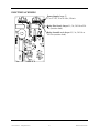
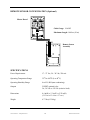
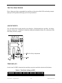
1
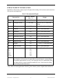
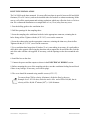
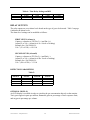
To r o n t o . O t ta w a . M o n t r é a l
London . Windsor. Edmonton
1-888-862-5356
E-mail: [email protected]
www.lev-co.com
VA-201M
Gas Monitor
USER’S MANUAL
Vulcain Alarm Inc. All Rights Reserved
DR0015 December 2002
WARRANTY
Vulcain Inc. warrants to the original purchaser that its product, and the component parts thereof,
will be free from defects in workmanship and materials for a period of one year from the date of
purchase. Vulcain will, without any charge and at its option, repair or replace defective products
or components upon their delivery to its Repair and Service Department.
This warranty does not apply in the event of misuse or abuse of the product, or as a result of unauthorized alterations or repairs. Vulcain shall not be liable for any consequential damages, including, without limitation, damages resulting from loss of use.
Every precaution for accuracy has been taken in the preparation of this manual. However, Vulcain
neither assumes responsibility for any omissions or errors that may appear, nor liability for any
damages that may result from the use of the products in accordance with the information contained in this manual.
Call Sales/Technical: 800-563-2967
Fax:
(450) 632-9938
BEFORE RETURNING ANY INSTRUMENTS, PLEASE CONTACT US TO OBTAIN A
RETURN OF MATERIAL AUTHORIZATION NUMBER.
To obtain warranty service, return the product, along with a complete description of the defect,
transportation prepaid. Vulcain assumes no risk for damage in transit. Following warranty repair,
the product will be returned to the buyer, transportation prepaid.
Warranty Registration
To validate the warranty, this registration form must be completed in full and sent to Vulcain within 90 days of the date of purchase.
Customer’s name:
Address:
City:
Location of the installation:
Serial no.:
Vulcain Alarm Inc. All Rights Reserved
State/Prov.:
1
DR0015 December 2002
TABLE OF CONTENTS
WARRANTY ...............................................................................................1
TABLE OF CONTENTS ............................................................................2
UNPACKING...............................................................................................3
DESCRIPTION............................................................................................3
INSTALLATION GUIDELINES...............................................................3
DETERMINATION OF NUMBER OF SYSTEMS.................................4
SURFACE-MOUNT INSTALLATION ....................................................5
RANGE AND ALARM LEVELS.................................................................6
DUCT-TYPE INSTALLATION ...................................................................7
DUCT-TYPE MOUNTING DETAILS.........................................................8
ELECTRICAL WIRING ............................................................................9
REMOTE SENSOR CONFIGURATION (Optional) ..............................10
SPECIFICATIONS .....................................................................................10
PERIODIC INSPECTIONS AND CALIBRATION ................................11
USER INTERFACE ....................................................................................11
TESTING PROCEDURE ...........................................................................12
ADJUSTMENTS..........................................................................................12
TIME DELAYS............................................................................................12
RELAY OUTPUTS......................................................................................13
FIRST LEVEL (Alarm A) .............................................................................13
SECOND LEVEL (Alarm B) ........................................................................13
DETECTION PARAMETERS......................................................................13
OPTIONAL DISPLAY..................................................................................13
Vulcain Alarm Inc. All Rights Reserved
2
DR0015 December 2002
UNPACKING
After opening the package, remove the equipment and components. Make sure that you have all
the items described on the order form or packing slip.
DESCRIPTION
The VA-201M-Series is an advanced microprocessor-based system featuring a high quality standalone monitor, a unique high-tech enclosure, and all necessary characteristics to provide continuous, effective and fully integrated monitoring of toxic and combustible gases.
INSTALLATION GUIDELINES
Make sure to locate the monitor and sensing assembly(ies) in an area easily
accessible to a technician.
Avoid any location where the monitor could be subject to vibrations.
Avoid any location close to noisy equipment.
Avoid any location where temperature variations occur rapidly.
Verify all the local requirements and existing regulations which may affect the
choice of location.
For the DT Duct-Type housing, installation is recommended on a straight duct at
least 3 feet (1 m) away from any curve.
Vulcain Alarm Inc. All Rights Reserved
3
DR0015 December 2002
DETERMINATION OF NUMBER OF SYSTEMS
The number of transmitters required is determined by a unit’s operational radius of surveillance.
Using Table 1 below, the number of units required can be easily evaluated.
Table 1:
Gas Detected
CO
NO2
Carbon Monoxide
Nitrogen Dioxide
Others
Vulcain Alarm Inc. All Rights Reserved
Radius of Surveillance
Area Covered
50 feet
(17 metres)
10,000 square feet
(1,000 square metres)
20 feet
(7 metres)
1,600 square feet
(100 square metres)
4
DR0015 December 2002
SURFACE-MOUNT INSTALLATION
Installation of the monitor simply requires the physical mounting of the enclosure and connection
of the power and output lines.
Table 2: Recommended Height
Detected Gas
Relative Density
(air = 1)
Height
CO
Carbon Monoxide
0.968
1 - 1.5 m (3 - 5 feet) from floor
* NO2
Nitrogen Dioxide
1.58 (cold)
H2
Hydrogen
0.07
30 cm (1 foot) from ceiling
CL2
Chlorine
2.50
30 cm (1 foot) from floor
NH3
Ammonia
0.59
30 cm (1 foot) from ceiling
H2S
Hydrogen Sulfide
1.19
30 cm (1 foot) from floor
HCL
Hydrogen Chloride
1.30
30 cm (1 foot) from floor
HCN
Hydrogen Cyanide
0.932
30 cm (1 foot) from floor
ETO
Ethylene Oxide
1.50
30 cm (1 foot) from floor
O2
Oxygen
1.43
1 - 1.5 m (3 - 5 feet) from floor
SO2
Sulfur Dioxide
2.25
30 cm (1 foot) from floor
R11
R12
R22
R123
R125
R134A
Refrigerants
5.04
4.20
3.11
5.27
4.14
3.52
30 cm (1 foot) from floor
COMB
Most combustibles are heavier than air, with the exception of methane, hydrogen, ethylene and acetylene. For gases that are heavier than air, sensors should
be installed approximately 30 cm (1 foot) from the floor. For combustibles that
are lighter than air, sensors should be installed 30 cm (1 foot) from the ceiling,
close to the potential leak source.
30 cm to 1 m (1- 3 feet) from
ceiling
* May differ in certain applications. Hot NO2 from exhaust systems is lighter than ambient air.
Vulcain Alarm Inc. All Rights Reserved
5
DR0015 December 2002
RANGE AND ALARM LEVELS
Table 3: Range and Alarm Levels
Gas Detected
Range
Alarm Level A
Alarm Level B
CO
Carbon Monoxide
0 - 250 PPM
35 PPM
200 PPM
NO2
Nitrogen Dioxide
0 - 10 PPM
0.72 PPM
2 PPM
CL2
Chlorine
0 - 15 PPM
0.5 PPM
1 PPM
NH3
Ammonia
0 - 100 PPM
25 PPM
35 PPM
H2S
Hydrogen Sulfide
0 - 50 PPM
10 PPM
15 PPM
HCL
Hydrogen Chloride
0 - 50 PPM
3 PPM
4 PPM
HCN
Hydrogen Cyanide
0 -50 PPM
5 PPM
9 PPM
ETO
Ethylene Oxide
0 - 10 PPM
1 PPM
5 PPM
O2
Oxygen
0 - 25% Vol.
19.5% Vol.
22% Vol.
SO2
Sulfur Dioxide
0 - 10 PPM
2 PPM
5 PPM
R-123
Refrigerant
0 - 1000 PPM
50 PPM
500 PPM
0 - 1000 PPM
0 - 2000 PPM
250 PPM
1000 PPM
500 PPM
2000 PPM
0 - 100% LEL
25% LEL
50% LEL
R-11
Refrigerants Q1
R-12
Q2
R-22
R-125
R134A
Combustibles
When the level of alarm has been reached, the corresponding relay will remain
activated for a minimum of 59 seconds.
A different alarm level may have been programmed in order to satisfy the constraint of a particular application.
Vulcain Alarm Inc. All Rights Reserved
6
DR0015 December 2002
DUCT-TYPE INSTALLATION
The VA-201M can be duct-mounted. It is most efficient when air speed is between 500 and 4,000
ft/minute (2.5 to 20.3 m/sec), and can be installed either for fresh air or exhaust monitoring. Make
sure to verify all the requirements and existing regulations which may affect the choice of its location. We recommend installation on a straight duct at 1 m (3 feet) away from any curve.
1. Post the drilling guide to the ventilation duct.
2. Drill the openings for the sampling tubes.
3. Insert the sampling tube with lateral air holes in the appropriate connector, orienting the air
holes facing airflow. Tighten with the (8-32 5/16”) screw on the connector.
4. Insert the exhaust tube into the appropriate connector, orienting the slant away from airflow.
Tighten with the (8-32 5/16”) screw on the connector.
5. For a ventilation duct longer than 20 inches (51 cm), extra tubing is necessary. It is preferable to
drill a hole at the opposite side facing the detection unit to support the far end of the tube. Seal the
end of the tube with the cork supplied. If necessary, seal the openings on the duct around the tubings.
6. Install the box on the duct.
7. Connect the power and the outputs as shown in the ELECTRICAL WIRING section.
8. Before mounting the cover of the sampling unit box, start the ventilation feeding fan and check
if there is any leakage. If necessary, seal with air plugs.
9. The cover should be mounted using metallic screws (6/32 1/2”).
To convert from CFM to velocity (ft/minute), divide the flow by the area.
Example: In a 2 ft X 4 ft duct, where the area is 8 ft2 and a CFM of 40,000, the air
velocity will be 40,000 ft3/minute/(8 ft2) = 5,000 ft/minute
Vulcain Alarm Inc. All Rights Reserved
7
DR0015 December 2002
DUCT-TYPE MOUNTING DETAILS
Vulcain Alarm Inc. All Rights Reserved
8
DR0015 December 2002
ELECTRICAL WIRING
Power Supply: Input J3
17 to 27 Vac, 24 to 38 Vdc, 250 mA
Relay First Level: Output J1, 5 A, 30 Vdc or 250
Vac (resistive load)
Relay Second Level: Output J2, 5 A, 30 Vdc or
250 Vac (resistive load)
Vulcain Alarm Inc. All Rights Reserved
9
DR0015 December 2002
REMOTE SENSOR CONFIGURATION (Optional)
Master Board
O
N
1 2 3 4 5 6
Cable Gauge: 18 AWG
J2
Maximum Length: 100 feet (30 m)
J3
Vulcain
S4
Remote Sensor
Assembly
J1
J2
TP51
P51
TP52
P52
SPECIFICATIONS
Power Requirements
17 - 27 Vac, 24 - 38 Vdc, 250 mA
Operating Temperature Range
32oF to 100oF (0 to 40oC)
Operating Humidity Range
0 to 95% RH (non-condensing)
Outputs
2 DPDT optional relay
5A, 30 Vdc or 250 Vac (resistive load)
Dimensions
8.4 in(H) x 5.3 in(W) x 2.25 in(D)
(21.3 cm x 13.4 cm x 5.7 cm )
Weight
0.77 lbs (0.350 kg)
Vulcain Alarm Inc. All Rights Reserved
10
DR0015 December 2002
PERIODIC INSPECTIONS AND CALIBRATION
Calibration should be performed twice a year. More frequent calibration may be necessary for
units operating under extreme conditions or exposed to contaminants or gas concentrations
greater than the lower explosive limits. A calibration inspection must be included as part of routine maintenance to ensure proper operation of the gas detection unit.
If unit span or zero cannot be adjusted, the sensor may be approaching its end-oflife or has been contaminated and must be replaced.
USER INTERFACE
After powering ON the monitor, the first 2 red LEDs will blink for 2 minutes during the warm-up
period, followed by the green LED indicating normal operation.
The yellow LED indicates a system failure. If this situation occurs, you should contact your local
representative for further assistance.
Each red LED represents 10% of the scale. For example, an oxygen depletion monitor reading
21% will light 8 red LEDs.
When the gas concentration reaches the first alarm level (Alarm A), the second red LED from the
top blinks and the first level relay is activated.
If the gas concentration reaches the second alarm level (Alarm B), the first red LED from the top
will blink. The second level relay and audible alarm are activated.
When the gas concentration exceeds the scale, all red LEDs flash ON and OFF.
For oxygen depletion detection only, the first level relay and audible alarm are activated when the concentration exceeds 22.0% and is less than 19.5%. In this case, relay
2 is never activated.
Stabilization time depends on the type of sensor used. Typically, most of the VA-201M-Q1 Series
stabilize within a few minutes, except for HCL, HCN and ETO units which stabilize fully in 7
days.
VA-201M-Q2 Series and VA-201M oxygen units will need a minimum of 24 hours before reading
within their specifications.
Vulcain Alarm Inc. All Rights Reserved
11
DR0015 December 2002
TESTING PROCEDURE
Flow a Span gas at the recommended rate and observe the action of the LEDs and analog outputs.
Span gas can be purchased through your local representative.
ADJUSTMENTS
The VA-201M comes as plug and play out of the box. Field adjustement is possible. All adjustments are factory set. If required, consult the additional information below for verification of the
time delays and relay output.
TP1: For Relay Adjustment
DIP1
TIME DELAYS
Switch 4 and 5 of DIP1 determine the time delay set prior to and after activation of the alarms.
Table 4: Time Delay Settings on DIP1
Switch 4
0 Min
OFF
Vulcain Alarm Inc. All Rights Reserved
1 Min
OFF
5 Min
ON
12
10 Min
ON
DR0015 December 2002
Table 4: Time Delay Settings on DIP1
Switch 5
0 Min
OFF
1 Min
ON
5 Min
OFF
10 Min
ON
RELAY OUTPUTS
The relay outputs are set at alarm levels based on the type of gas to be detected. Table 3 on page
6 indicates the alarm levels.
The alarm level settings can be modified as follows:
FIRST LEVEL (Alarm A)
Connect a voltmeter to TP1 Pin 3 (+) and Pin 6 (-).
Adjust P1 to Vdc = (Alarm level A x 4/scale of reading)
Example for a VA-201M-CO:
Vdc = (35 x 4/250) = 0.56 Vdc
SECOND LEVEL (Alarm B)
Connect a voltmeter to TP1 Pin 2 (+) and Pin6 (-).
Adjust P1 to Vdc = (Alarm level B x 4/scale of reading)
Example for a VA-201M-CO:
Vdc = (200 x 4/250) = 3.2 Vdc
DETECTION PARAMETERS
Table 5:
Alarm A
Actions
Alarm B
Actions
OPTIONAL DISPLAY
An LCD display is available in order to visualize the gas concentration directly on the monitor.
Toxic gases appear in parts per million, flammable gases in percentage of lower exposure limit,
and oxygen in percentage per volume.
Vulcain Alarm Inc. All Rights Reserved
13
DR0015 December 2002