1
Downloaded from http://www.everyspec.com
MIL-STD-187-31O
●
14
MILITARY
STANDARDS
●
OCTOBER
1976
STANDARD
FOR 10NG HAUL COMMUNICATIONS
SWITCHING
PLANNING STANDARDS
FOR THE DEFENSE COMMUNICATIONS
SYSTEM
SLHC
Downloaded from http://www.everyspec.com
MIL-STD-187-31O
DEPARTMENT
OF DEFENSE
WASHINGTON
, D. C.
20306
Switching Planning Standards for
the Defense Communications System
MIL-STD-187-31O
1. This Military Standard is approved for use by all Departments
and Agencies of the Department of Defense .
2. Beneficial comments (recommendations, additions, deletions) and
any pertinent data which may be of use in improving this document, should
Engineering
Center,
be addressed to Director, DefenseCommunications
ATTN : Code M1O, 1860 Wiehle Avenue, Reston, Virginia 22090, by using
the self-addressed Standard ization Document Improvement Proposal (DD Form
1426) appearing at the end of this document or by letter.
ii
Downloaded from http://www.everyspec.com
MIL-STD-187-31O
FOREW08D
1. Electrical performance standards for the Defense Communications
Systsm (DCS) are contained in the MIL-STD-188-1OO and 300 series of
documents. These standards, which apply primarily to today’s analog
system, contain performance values which must be within the state-ofthe-art and based on measured performance of actual equipment and
circuits . Since standards are the basis for specifying equipmsnt to
be procured or reprocured for use in the DCS, they provids assurance
that new equipment will perform satisfactorily and interface properly
with other equipment in the DCS.
2. At present, the standardization coverage of the DCS is fairly comprehensive. lhis is due to the relatively stable configuration of the
DCS since completion of the major switched subsystems, which has perCurrently, however, the DoD
mit ted standards development to “catchup.”
is entering a period, of perhaps ten years or more, during which mnny
major changes are planned in the DCS. Unless some modification is
made to the DoD standards program, standards will continue to be
developed essentially after-the-fact, and will be of little help in
planning and designing these forthcoming changes. Accordingly, the
standardization effort is being expanded to include the development
of “future” or planning standdrds for the DCS. These standards are
being developed at an earlier date than, and are to be forerunners of,
conventional standards.
3. DCS Planning Standards contain characteristics which apply to the
evolving and future DC S. Performance values assigned to these characteristics may meet the same criteria as conventional standards, i.e. ,
proven by measured performance, etc. , or they may be based on best
technical judgment of what is needed for the future. In some cases,
performance values have not been determined as yet and their definition
maY depend upon the completion of related studies or 8DT&E programa.
This category of unknown performance values serves to idsntify and,
in a sense, reserve these areas until agreed-upon values can be
established. This tends to preclude unilateral decisions by designers
that might preempt the opportunity of making a better choice later on.
4. Planning standards provide uniform guidance for the design of the
evolving and future DCS. Providing this guidance at the concept
engineering stage will help to minimize ineffective designs and costly
fnteroperability problems at later stages of implementation, as well
as assuring utilization of appropriate advances in technology. Also ,
establishing a reference source of design guidance will: minimize
unilateral design dec:lsionsby one project engineering group; pinpoint
areas where design decisions are needed; facilitate the comparison and
iii
Downloaded from http://www.everyspec.com
MIL-STD-187-31O
evaluation of design criteria in regard to tradeoffs and impact on
other subsystems and overall system performance; and provide wider
exposure of design decisions’ to all interested DoD activities.
5. The need for inceroperability with other DoD and non-DoD systems
has been a major consideration in the development of planning standards. Specifications for the characteristics and parameters in the
planning standards were developed considering present specifications
and future plans for the TRI-TAC system, commercial systems (both
national and international), and NATO/NICS. Also considered was the
Final Report of the DoD Commit tee on Interoperability and DoD, national
and international communication system standards.
6.
It is planned to develop planning standards in the following areas:
a.
Network and System Design
b.
Switthing
c.
Secure Communications
d.
Transmission
e.
Satellites
f.
Terminals
g.
System Management and Centrol
h.
Survivability.
‘Ibisplanning standard, for switching, is the first to be developed.
An analysis has been made of the evolving and future DCS, as planned,
to determine what switching planning standards are needed. Services
and features which will differ from those in the present DCS, thereby
requiring new design effort or design decisions, have been identified
and broken down into specific subject areas, characteristics, and
parameters. Technical descriptions of these characteristics and
parameters have been prepared which represent a technical snapshot
of where DCA/DoD stands in defininglspecifying them for the evolving
and future DCS.
7. In order to provide a reference for the switching planning standard, a description of the evolving and future DCS, together with
the aforementioned analysis, is provided and is divided into time
periods. The first time period applies “to the Nominal Future DCS,
which is a configuration based on logical extensions of ongoing programs; i.e. Phase II Secure Voice, AUTODIN II, and a DCS-suitable
AN/TTc-39 . This period is considered herein as the 1976-1986 time
iv
Downloaded from http://www.everyspec.com
MIL-STD-187-31O
period, although full implementation of these programs may extend
beyond 1986. The second period applies to the Future DCS - Advanced
Concepts, the definition of which depends on the ability to take
advantage of evolving technologies. This period is considered the
post-1986 time period, although advanced concepts could be implemented
earlier. Switching planning standards applicable to the post-1986
time period will be based on the results of advanced R6D pertaining
to a unified switch. This will provide a frame of reference for
judging performance requirements or acceptability of intermediate
switching applications; e.g. AN/TTC-39.
Downloaded from http://www.everyspec.com
MIL-STD-187-31O
CONTENTS
i“m.EwoRD
CONTENTS
CHAPTER
1.
SCOPE
1-1
2.
REFERENCED DOCUMENTS
2-1
3.
TEF44s, DEFINITIONS Am
4.
THE PRESENT DCS
4-1
5.
THE FUTURE DCS
5-1
6.
CIRCUIT SWITCHING
6-O-1
SECTION 1 - NUMSERING HAN
6-1-1
SECTION 2 - SERVICE FEATURES
6-2-1
SECTION 3 - INFORMATION TONES AND RECOROEO ANNOUNCEMENTS
6-3-1
SECTION 4 - SIGNALING AND SUPERVIS ION
6-4-1
SECTION 5 - ROUTING
6-5-1
SECTION 6 - INTERFACES
6-6-1
SECTION 7 - CIRCUIT SWITCH CHARACTERISTICS - OVERSEAS
6-7-1
SECTION 8 - CIRCUIT SWITCH CHARACTERISTIC S - CONU S
6-S-1
ACRONYMS
vi
3-1
Downloaded from http://www.everyspec.com
MIL-STD-187-31O
CONTENTS - Cant inued
233E
CHAPTER
DATA SWITCHING
7-o-1
SECTION 1 - SYSTEM PERFORMANCE REQUIREK2NTS
7-1-1
SECTION 2 - FUNCTIONAL REQUIREMENTS
7-2-1
SECTION 3 - PROTOCOLS
7-3-1
SECTION 4 - PACXET SWITCH CHARACTERISTICS
74-1
SECTION 5 - AUTODIN II SYSTE?lCONTROL
7-5-1
SECTION 6 - AuTOD2N II SOFTWARE
7-6-1
ACCESS AREA
8-o-1
SECTION 1 - DIGITAL ACCESS EXCHANGE (DAX)
8-1-1
SECTION 2 - LOCAL DIGITAL MES SAGE EXCHANGE (LDMX)
8-2-1
B’ECTION 3 - COMMUNICATIONS ACCESS PROCESSOR (CAP)
8-3-1
SECTION 4 - PRIVATE AUTOMATIC BRANCH EXCHANGE (PABX)
8-4-1
SECTION 5 - COMMUNICATIONS SELECTOR SWITCH (CSS)
8-5-1
SECTION 6 - INTERPACES
8-6-1
9.
SYSTEM CONTROL ELSMENTS APPLICABLE TO SWITCHING
9-o
10.
FUTURE DCS - ADVANCSD CONCEPTS
104-1
SECTION 1 - UNIFIED DIGITAL SWITCH (UDS)
10-1-1
SECTION 2 - SOFTWARE
10-2-1
7.
8.
●
vii
Downloaded from http://www.everyspec.com
MIL-STD-187-31O
FIGURES
EK!+
Figure
5.1
6.1.1
6.1.2
6.4.1
6.4.2
6.4.3
6.4.4
6.4.5
6.4.6
6.4.7
6.4.8
6.4.9
6.5.1
6.5.2
6.5.3
7.2.1
7.3.1
7.3.2
7.3.3
7.3.4
7.3.5
7.3.6
7.5.1
8.1.1
10.1.1
10.1.2
10.1.3
Future DCS Generic Configuration
Message Format for Call Initiate
To Be Used by Switches with CCS
Message Format for Call Initiate
to be Used by Switches with Digital
In-Band Signaling
Trunk Signal ing Buffer
MUX/DRMOX Subchannel Allocations
Format of Call Initiate Message
Format of Call Complete Message
Format of Call Answer, Release,
Call Incomplete (Except Invalid
Route) , Trunk Test, and Special
Mes sages
Format of Acknowledgment and Test
Sync Messages
Format of Invalid Route Message
Format of Sync A and Sync B Messages
Typical Message Sequence
Basic Pattern of Polygrid Network Structure
Home Grid Array
Order of Trunk Group Cluster Selection
Standard Interface Between Data
Terminal Bquipment and Data
Communicantion Equipment
Protocol Structure
Binary Segment Leader
Effect of Line Modes
Type A Binary Segment Leader Mode VI
Procese-To-Process Transfer of Information
Type B - Packed Binary Segment
Leader/Mode I
System Control General Message Format
DAX System Concept
Frequency-Time Representations
Multiplex Structure for Typical Frame Period
Functional Structure for Future Switch
Architecture
viii
5-7
6-1-11
6-1-12
64-3
6-4-4
6-4-6
6-4-7
6-4-7
6-4-8
6-4-8
6-4-8
6-4-12
6-5-2
6-5-3
6-5-13
7-2-10
7-3-2
7-3-6
7-3-7
7-3-8
7-3-12
7-3-15
7-5-4
8-1-2
10-1-12
10-1-13
10-1-16
Downloaded from http://www.everyspec.com
MIL-STD-18 7-310
L 1ST OF TABLES
QYE
Table 6.1.1
Subscriber Dialed Information
6-1-3
6.1.2
Allowable Subscriber Dialed Sequences
6-1-7
6.1.3
Allowable Trunk Dial I.ng Sequences
6-1-14
6.3.1
Information Tones Provided to
6.4.1
Trunk Signal Ing Messages
6-4-9
6.5.1
Route Control Digit Meanings Exterior
to Home Grid
6-5-5
6.5.2
Route Control Digit Meanings in Home Grid
6-5-6
6.5.3
Trunk Selection Rules at an Originating
or Gateway Switch
6-5-10
6.5.4
Trunk Selection Rules at an Intermediate
Node Which is Not a Gateway
6-5-11
7.1.1
Traffic Acceptance Categories
7-1-8
7.1.2
Precedence Category
7-1-1o
7.2.1
Subscriber/Constraint Matrix
7-2-6
7.2.2
Subscriber/Subscriber
Cross-Connection Matrix
7-2-8
7.2.3
Subscriber Interchange
Capabilities and Leader Formats
7-2-9
7.3.1
Binary and Character Oriented
Subscriber Characteristics
7-3-4
8.1.1
Special Service Features
8-1-8
1461%?
ix
theSubscriber
6-3-3
Downloaded from http://www.everyspec.com
MIL-STD-187-31O
CHAPTER 1
SCOPE
1.1 Purpose. This planning standard establishes a reference source of
unified systsm design guidance applicable to the evolving and future
Defense Communications Systsm (DCS). This guidance is intended to help
assure the compatibility nf future DCS subsystems. as well as the interoperability of the DCS vith other DoD and non-DoD cornmunications systems.
Specifically, this planning standard is intended to:
a.
Avoid unilateral design decisions by one engineering group
b.
Pinpoint areas where design decisions are needed
c.
Facilitate the comparison and evaluation of design criteria
in regard to tradeoffs, impact on other subsyetems, and overall system performance
d.
Assure ul:ilization of appropriate advances in technology
e.
Provide wider exposure of design decisions to all interested
DoD activities.
1.2 Application.
This planning standard is to be used in the planning
and dss ign of future DCS subsyst ems, as well as programs for communications facilities to be used in, or that interface with, the DCS. This
planning standard is to be used as a basis for preparing system and
equipment development specifications (Types A and B respectively, as
described in MIL--STD-49O), but should not be used for preparing procurement specifications, since it is subject to change as the design of the
future DCS evolves’and is refined.
1-1
Downloaded from http://www.everyspec.com
MIL-STD-187-31O
CHAPTER 2
REFERENCED DOCUMENTS
2.1 This document is arranged in chapters and sections with page
numbers keyed to the chapters and sections. For example, page 5 of
section 4 of chapter 6 is numbered 6-4-5. This format is bein8 used
initially so that changes can be made and new material inserted
For the same
without extensive retyping, page renumbering, etc.
reasons, referenced documents have been decentralized. References
pertaining to a particular section are listed under the last paragraph
of that section. Reference keys in the text consist of small letters
in brackets, e.g. [a]. Requests for information on how references
may be obtained should be addressed to Director, Defense Communications
Engineering Center, ATTN: Code R11O, 1860 Wiehle Avenue, Reston,
Virginia 22090.
2-1
Downloaded from http://www.everyspec.com
MIL-STD-187- 310
CHAPTER 3
TERMS , DEFINITIONS AND ACRONYMS
3.1 Terms and Definitions. Standard definitions for telecommunications
terms used in this document may be found in MIL-STD-188-120, “Common
Long Haul/Tactical Telecommunications Terms and Definitions ,“ presently
in the final stages of development .
3.2
Acronyrrs
ACRONTM
MEANING
ACOC
Area Communications Operat ions Center
A/D
Analog (to) Digital
ADCCP
Advanced Data Communication Control Procedures
ADI
Analog/Digital Interface
ADP
Automatic Data Processing
AMllE
Automated Multi-Media Exchange
Af04
Asynchronous Response Mode
ARPA
Advanced Research Projects Agency
ARQ
Automatic Repeat Request
ASC
Automatic Switching Centex
ASCII
American Standard Code for Information Interchange
ATB
All Trunks Busy
ATEC
Automatic Technical Control
ATP
Automated Telecommunications Program
AUTODIN
Automatic Digital Network
AUTOSEVOCOM
Automatic Secure Voice Communications
3-1
Downloaded from http://www.everyspec.com
MXL-S’KI-187-31O
ACRONTM
MsANING
AUTOVON
Automatic Voice Network
BCS
Backbone Circuit Switch
:*EC
Buffer and Executive Control
BPS
Backbone Packet Switch
ble
Bits Per Second
BSC
Binary Segment Leader
CAP
Communications Access Processor
CCIR
Consultative Committee International Radio
CCIS
Common Channel Interoffice Signaling
cc ITT
Consultative Committee International Telegraph
and Telephone
Ccs
Common Channel (Interoffice) sig~ling
CCSL
Character Canned Segment Leader
CID
Channel Identifier
CNCE
Communications Network Control Element
COL
Communications Oriented Language
COMSEC
Communications Security
CRC
Cyclic Redundancy Check
cRT
Cathode Ray Tube
CSL
Character Segment Leader
CSN
Channel Sequence Number
Css
Communications Selector Switch
CUSL
Character Unclassified Segment Leader
3-2
Downloaded from http://www.everyspec.com
MIL-STD-187-31O
MSANING
ACRONTM
CVSD
Continuously Variable Slope Delta Modulation
DA-TDMA
Demand Assigned-Time Division Multiple Adcess
DAX
Digital Access Sxchange
DCA
Defense Communications Agency
DCACC
DCA Operations Center
DCS
Defense Coummnications System
DDD
Direct Distance Dialing
DMA
Direct Memory Access
DOCC
DCA Operations Complex
DSCS
Defense Satellite Communications System
DSVT
“
Digital Subscriber Voice Terminal
DTG
Date-Time-Group
DTKF
Dual Tone Mul tifrequency
ECP
Engineer ing Change Proposal
11’fP
Electromagnetic Pulse
EOM
End of Message
ETS
European Telephone System
FCS
Flag Check Sequence
FDM
Frequency Division Multiplexer
FOC
Full Operational Capability
Gos
Grade of Service
GTS
Go to Sync
HSMF
High Altitude Electromagnetic Pulse
3-3
Downloaded from http://www.everyspec.com
MIL-STD-187-31O
MEANING
ACROWM
HLP
Host Level Program
HOL
Higher Order Language
11A
Interactive
IASA
Integrated AUTODIN System Architecture
ICAT
Intermediate Capacity Automated
Telecommunications System
!lCu
Interface Control Unit
IOC
Initial Operational Capability
K
Key Genera tar
Kbls
Kilobits Per Second
RDC
Key Distribution Center
LC
Line Control
LDMK
Local Digital Message Exchange
LJIF
Language Media Format
Mb/s
Megabits Per Second
MCATS
Medium Capacity Automated Telecommunication
system
MCCU
Multiple Channel Control Unit
MLPP
~Multilevel Precedence and Preemption
MP
Microprograms
MTBF
Mean Time Between Failures
MTTR
Mean Time to Repair
NATO
North Atlantic Treaty Organization
NAVCOMPARS
Naval Communications Processing and
Rout ing System
Downloaded from http://www.everyspec.com
MIL-STD-187- 310
ACRONYM
MEANING
NCS
National Communications System
NCC
Network Control Center
NICS
NATO Integra ted Communicantions Sys tetn
NID
Network Inward Dialing
NOD
Network Outward Dialing
NSWT
Nonsecure Warning Tone
NvT
Network Virtual Terminal
OCR
Optical Character Reader
o&M
Operating and Naint enance
OSRI
Originating Station Routing Indicator
OSSN
Originating Station Serial Number
PABX
Private Automat ic Branch Exchange
PAN
Programmed Assigned Number
PBSL
Packed Binary Segment Leader
PBX
Private Branch !Zxchange
Pm
Pulse Code Modulation
PH
Packet Header
PLA
Plain Language Addressing
PSN
Packet Switching Node
PTF
Patch and Test Facility
PWIN
Prototype WWMCCS Integrated Network
QOS
Quality of Service
Q/R
Query/Response
3-5
Downloaded from http://www.everyspec.com
MIL-STD-187-31O
MSANING
ACRONYM
RBS
Ringback Secure
RBN
Ringback Nonsecure
ROT&E
Research, Development, Test and Evaluation
RI
Routing Indicator
RXR
Receive Not Ready
RR
Receive Ready
RSC
Record Service Center
RV
Ring Voice
SATIN IV
SAC Automated Total Information Netvmrk
Sc
Switch Centrol
Sccu
Single Channel Cant ro1 Unit
SDMX
Space Division Matrix
S/F
Store and Forward
S1P
Segment Interface Protocol
SL
Segment Leader
SOM
Start of Message
s/s
Signaling and Supervision
system control
TAC
Terminal Access Control
TCC
Transmission Control Code
TCF
Technical Control Facility
TCCF
Tactical Communications Control Facilities
TCP
;
Transmission Control Program
3-6
Downloaded from http://www.everyspec.com
MIL-STD-187-31O
ACRONYM
o
MSANING
TDM
Time Division Multiplexer
TDMS
Time Division Matrix
TsO
Trunk Encrypt ion Device
TF
Test Facility
TGC
Trunk Group Cluster
TH
Terminal Handler
TSB
Trunk Signaling Buffer
TTY
Teletypewriter
ULs
Unit Level Switchboard
UDs
Unified Digital Switch
liAVCS
Washing ton Area Wideband Communicantions System
WwMccs
Worldwide Military Command and Centrol Systern
WWOLS
Worldwide On-line System
3-7
Downloaded from http://www.everyspec.com
MIL-STD-187- 310
CHAPTER 4
THE PRESENT DCS
4.1
The DC S is the single, wnrldwide complex comprising all long-haul
point-to-point communications facilities, associated personnel, and
material within the DoD. It is primarily a long-haul, general purpose
aye.
tem of government-owmed and leased transmiaaion madia, relay
atationa, and switching centers. The composite DCS ia a very extensive and complex syat em located in 70 countries throughout the world.
Engineering, operating, and maintenance functione for the DCS require
over 16,000 DoD personnel, both military and civilian, including
about 2,700 DCA personnel. Employees of operating telephone companies,
record carriers, and other suppliers of leased vnice and data awitchea
are not included in these figures. The annual 06M costs are about
$500 million. The DCS comprises three major networks; AOTOVON,
AUTODIN, and AUTOSEVOCOM.
●
4.2 Automatic Voice Network (AUTOVON) . AUTOVON is the principal longhaul, nonsecure voice communications network in the DCS, and has over
500,000 users comected by 15,000 access lines. It handles approximately 750,000 originating calls a day. The 65 automatic switches
located in the United States and Canada are comected in a targetavoidance routed polygrid scheme and are leased from independent and
Bell Telephone operating companies. There are 16 AUTOVON ewitches
ic,1 in Panamaand10 in Europe.
located overseaa: 5 in thePaclf
Withtheexception
of theswitchin Hawaii,whichia leased,all are
AUTOVONsurvivability
is limitedby availmilitaryoperated.Overseaa
ableInterswltch
tranamlsaicm
media.
4.3 Automatic Digital Network (AUTODIN) . AUTODIN 1S the principal
record communications system of the DCS. It is a secure, computercontrolled store-and-forward syetem which handlea approxinmtely
350,000 meaaages a day. Nine AUTODIN ewitches are located on military
installations in CONUS and Hawaii, with equipment and services leased
from West ern Union Company. Eight additional switches are located overseas, and are operated by the military departments. AUTODIN intersvitch trunking la not aa survivable as CONUS AUTOVON. However,
alternate routing for AUTODIN via AUTOVON ia available by dial-up. The
17 AUTODIN switches are interconnected by 52 interswitch circuits and
serve approximately 1400 terminals, 600 of which are teleprinters.
AUTODIN accepta and delivers traffic in a variety of modes: teletypewriter punched cards, nxigneticand paper tape, and some claases of
computer-to-computer traffic. Transmission rates vary, according to
subscriber needs , from 45 to 4800 baud.
Downloaded from http://www.everyspec.com
MIL-STD-187-31O
4.4 Automatic Secure Voice Communications (AUTOSEVOCOM) . AUTOSEVOCOM
is a secure voice subsystem serving approximately 1400 subscribers
throughout the world and consists of two types of service. First,
there are enclaves of subscribers equipped with 50 kb/s XY-3 terminals
homed on wideband switches . These subscribers can make high quality
intraswitch calls. In addition, certain of these wideband switches
are interconnected by videband circuits and thus offer high quality,
long-haul , secure VOiCe service where available. The second type of
service utilizes the SIT-2,operating over the nominal 4 kHz analog
media of AUTOVON at 2400 baud. The HT-2 voice processor is a vocoder,
and sounds artificial. User acceptance is usually directly relatable
to experience in using the syatsm. It is difficult to use for the
infrequent subscriber and under conditions of stress, when procedures
for proper use rway not be carefully observed, the service tsnds to
degrade rapidly. Inadequate transmission media, the complications
of remote locations, and aometimsa improperly maintained subscriber
terminal equipment, have resulted in occasional failure to provide
urgently required secure voice service. Aa an augmented service at
selected locationa, the HY-11, using continuously variable slope delta
(CVSD) modulation technique, has been operating at 9.6 kb/s on the
same nominal 4-kHz analog med la. In addition to providing some
improvement over the HY-2 in both voice intelligibility and quality,
the fiT-11 is rmre tolerant of transmission media and imperfect maintenance than is the HY-2. Narrovband subscribers have @ccess to the
wfdeband enclavea through narrowband-to-wideb and convers ion equipment,
although the interface is presently a manual operation. The various
tYPes of equipment utilized in the secure voice network requires an
inordinate call setup procedure and quite complsx calling instructions.
Key distribution for a large number of subscribers on these dissimilar
crypto devices is a logistics task of large proportions.
4.5 The European Telephone System (ETS). The ETS, which provides nontactical, general purpose, cowmon user, voice telephone semice for
U.S. Forces in Central Europe, vaa recently placed under DCA managemen t. The ETS switching network consists of five tandem switching
centers and 24 intermediate switching centers, interconnected via 4-wire
interswitch trunks. This system will interconnect via Z-wire access
trunks, 130 PBx’ s which service 68,000 main telephone lines, all of
which are managed, operated, and maintained by the owning military
departments. Wnen operational, this system will replace the USAREUR,
USARERU DSA, and USAF VF Dial Systems.
4.6 In addition to the three common-user switched networks and the
ETS, the DCS contains numerous specLal-purpose or dedicated networks.
The future integrated digital DCS should be able to absorb most of
these dedicated networks into the integrated switched system while
still providing the needed services [a].
4-2
a
Downloaded from http://www.everyspec.com
MIL-STD-187-31O
4.7
References
[a]
DCEC ‘.CR20-75, “Engineering Concept for IYJSTransition (U) ,”
December 1975 (SECRET) .
4-3
Downloaded from http://www.everyspec.com
MIL-STO-187-31O
CHAPTER 5
THE FUTDRS DCS
CONTSNTS
Paragraph 5.1
5.1.1
5.1.1.1
5.1.1.2
5.1.1 .2.1
5.1.1 .2.1.1
5.1.1 .2.1.2
5.1.1 .2.1.3
5.1.1 .2.2
5.1.1.3
5.1.2
5.2
5.2.1
5.2.2
5.2.2.1
5.2.2 .1.1
5.2.2 .1.2
5.2.2.1,3
5.2.2.2
5.2.2 .2,1
5.2.2 .2.2
5.2.2.2.3
5.2.2 .2,4
5.2.2 .2,.5
5.2.3
5.2.3.1
5.2.3 .1.1
5.2.3.1.2
5.2.3 .1,,3
5.2.3 .l..
&
5.2.3.2
5.2.3.2.1
5.2.3 .2.2
5.2.3.2.3
5.2.3 .2.4
5.2.3 .2.5
5.3
5.3.1
5.3.2
Program Developments (1976-1990)
Phase II Secure Voice (P2SV)
Introduction
System Description
Switthing
AN/TTc- 39
ESS No. 1 Modification
Digital Access Pxchange
Other System Features
Transit ional Aspects
AUTODIN II
The Nominal Future DCS
Generic Configuration
Switthing Subsystem Elaboration
Backbone Switching
Backbone Circuit Switch
Backbone Packet Switch
Record Service Center
Accea a Area Switthing
PBX
DAX
LDMX
Cormnunications Access Processor (CAP)
Communications Selectnr Stitch (CSS)
Planning Standards Requirements
Overseae DCS
Voice
Data
Special Services
Access Area
CONDS DCS
Clear Voice
Secure Voice
Data
Special Services
Access Area
The Future DCS - Advanced Concepts
Overview
Switthing Subsystem E2aborat ion
and Planning Standards Requirements
5-1
5-3
5-3
5-3
5-3
5-3
5-3
54
5-4
5-5
5-6
5-6
5-8
5-8
5-11
5-22
5-12
5-12
5-12
5-12
5-12
5-13
5-13
5-14
5-14
5-14
5-15”’”
5-15
5-16
5-17
5-18.
5-18
5-18
5-19
5-19
5-19
5-19
5-?0
5-20
5-21
..
,., .
.,,’
Downloaded from http://www.everyspec.com
MIL-STD-187-31O
CONTE~S
Paragraph 5.4
5.4.1
5.4.2
5.4.3
5.4.4
5.5
5.6
- Continued
Areas Deserving Special Emphasis
Signaling and Supervision
System Control
Secure Communications
Interoperability
Summary of Planning Standards
Requirements
References
5-2
5-21
5-21
5-22
5-22
5-22
5-22
5-23
Downloaded from http://www.everyspec.com
MIL-sTD-187-31O
CHAPTER 5
THE FUTURS DCS
5.1 Program Developments (1976-1990~. Major changes in DCS switching
are required during the 1976-1986 time period to support the AUTOSEVOCOM
II and AUTODIN II programs. AUTOSEVOCOM II will require modification
of the CONUS AUTOVON No. 1 ESS switches and replacement of Overseas
AUTOVON switches with the AN/TTC-39 to provide a digital switching
capability. Also Digital Access Exchanges (DAX) will be provided to
concentrate digital secure voice traffic in the access areas. Under
the AUTODIN II program, packet switches will be installed to provide
a general purpose, data communications switched network to meet computer
communications requirements. These switches and related program features
and estimated implemental ion time periods are df scussed in the paragraphs
following.
5.1.1
●
AUTOSSVOCOM 11
5.1.1.1 Introduction. The proposed AUTOSEVOCOM II system is defined as
the DCS single integrated worldwide secure voice communications system.
It is designed to provide a high quality, fully automatic system which
will also interoperate with the TRI-TAC secure voice system.
The system will replace the existing AUTOSEVOCOM I system commencing
in 1980. It will be configured to serve 2500 secure voice subscribers
initially, 10,000 subscribers by 1985 and will have thecapability to
expand further to meet future secure voice needs.
5.1.1.2 System Description. AUTOSSVOCOM II will provide an integrated
worldwide backbone 16 kbps digital system for secure voice communications.
5.1.1 .2.1 Svitch:lng. In CONOS, AUTOVON ESS No. 1 switches will be
modified for wideband digital service and will amulate the TRI-TAC
AN/TTC-39 switch. Initially, approximately 20 of the CONDS switches
will be modified for digital service. In the overseas areas, AN/TTC-39
switches will replace the existing AUTOVON switches. This switching
configuration permits direct interconnectivit y, without modification,
of the TRI-TAC equipment in the DCS and thereby preserves the commonality
of equipment within the DCS and between the DCS and TRI-TAC. In the
access area, Digital Access Exchanges (DAX) will be used to concentrate
digital secure voice traffic .
5.1.1 .2.1.1 AN/TTc-39 . The AN/TTC-39 family of circuit switches will
provide the DCS with transportable (fixed installation) automatic
5-3
Downloaded from http://www.everyspec.com
MIL-STD-187-31O
switching systems with voice switching capability, communication
security capability and circuit switched data communications capability.
The circuit swftches will serve both analog, (4 kHz and wideband) and
digital traffic, and will make use of a flaxible stored-program control
system. This stored program will give the capability for insertion, or
removal of functions or services prior to, and during switch deployment
by altering the subscriber classmarks and the data base resident in the
switch memo ry. These switches will interface with the axiating AUTOVON
circuit switches on an interswitch trunk basis ~ well as a ?BX access
line baais. In addition, they will interface with their tactical
counterpart AN/2TC-39 circuit and message switches , as well as with
other tactical switches such as the AN/TTc-38, AN/TTC-30 and AN/TTC-25.
Interfaces with other systems include NATO and commercial carriers.
The AN/TTC-39 will incorporate an Automatic Key Distribution
Center and associated key generators for loops and trunks. The interawitch trunks will be provided link encryption protection whereas the
loops terminated with DSVT’s will be provided end-to-end protection by
the terminal security device. Inventory COMSEC equipments such as
KT-3’s and Narrowband Secure Terminals (HY-2 and KT-11) will be able
to place calls through the analog matrix and through the loop-around
trunks which provide both key conversion and mode conversion.
The AN/TTC-39 is of modular design so that a basic switch can provide growth capability from 120 to 600 external terminations per switch,
and this mdularity also permits the exchange of one analog module for
one digital module in the same physical space. The analog module size
is 156 terminations of which 120 are external terminations ; and the
digital module size is 256 terminations of which 150 are external
terminations.
5.1.1 .2.1.2 ESS No. 1 Ffodification. In CONUS, the AN/TTC-39 switching center would be emulated by the modification of selected AT6T
ESS No. 1 switches. The present ESS No. 1 is an analog switch.
A portion of the switch would be modified for digital service while
the remainder of the switch will continue to provide analog service.
Digital line units and trunk units will be added to the switch to provide an interface with the new 16 kbps digital subscriber voice terminals
(DSVT) and digital incerswitch trunks. The call processing software program of the ESS No. 1 will be modified to perform the necessary interface
communicantions with the TSNLEY COMSEC unit. The switch software program
will also be modified to provide a Common Channel Signaling (CCS) capability to permit a trunk interface with the TRI-TAC AN/TTC-39.
5.1.1 .2.1.3 Digital Access Exchange (DAK). Small circuit switches”
(DAKs) are to be located in the access area to concentrate digital
secure voice traffic. It is envisioned that the DAX will be a family
5-4
Downloaded from http://www.everyspec.com
MIL-STD-187-31O
of access switches developed to meet the needs of immediate short term
programs and also the need to transition to a longer range more
digitized DCS. The DAX will service secure voice users and selected
bulk data users, the latter operating primarily during non-busy hours
in order to maintain the CDS designed for Secure Voice users and to
provide greater transmission plant efficiency. The basic DAK will be
a four-wire, fully automatic, common control switch operating at 16 kbps.
It will provide dig~.tal access line terminations and interfaces for
digital AUTOVON switches in the CONUS, AIN/TTC-39 type switches Overseas ,
and DAK-DAX tie lines for tandsm operation. It is intended that the
DAX will not contain any crypto elements, and therefore can be treated
as a BLACK switch far COMSEC purposes. It will be compatible with
TENLEY COMSEC procedures . Digital signaling and supervision will be
provided. The basic DAK will be capable of having 90 subscribers, and
fabricated in depopulated models to meet the 60 and 30 subscriber requirements.
5.1.1 .2.2
●
Other System Features
a. AUTOSEVOCOM 11 will provide a 16 kbps terminal for DCS secure
voice users. The terminal will be tbe TRI-TAC digital subscriber voice
terminal (DSVT). Those users who cannot be provided 16 kbps transmission
facilities economically will use a narrowband terminal and 4 kllzor lowrate digital facilities with a narrowband/wideb and converter.
b. An alternate clear voice/secure voice capability will be provided to all subscribers. Also, the network will permit calls between
digital subscribers and analog subscribers. The switch will insert an
analog-to-digital converter between the analog and digital portion of
the matrix when this type of connection is required.
Inband digital signaling and supervision will be used by the
c.
terminals on access lines. Digital common channel signaling (CCS) will
be used on interswitch trunks.
d. Automatic remote electronic cryptographic key distribution
will be provided on a call-by-call basis by use of the TRI-TAC TENLEY
Key Distribution Center (KDC) in both CONUS and Overseas.
Therefore,
the TENLEY COMSEC will be identical on a worldwide basis for the DCS
and TRI-TAC networka.
e. The Phase II Secure Voice lietworkwill be digital and will
operate synchronously. A stable clock source will be provided at each
modified ESS No. 1 switch. Clock timing, contained in the data stream,
will be transmitted to each subscri~er terminal. The terminal will
extract the timing for internal use. The clock will also furnish timing
on the interswitch trunks between switches.
5-5
Downloaded from http://www.everyspec.com
MIL-STD-187-31O
f. A full duplex conferencing capability will be made available
in both CONUS and Overseas.
6. End-to-end encryption will be provided for all secure calls
within the DCS network except for conferencing, which may require a
KED breakout.
h. TKI-TAC Interoperability can be provided on a direct and-toend encrypted basis tith both the CONUS and overseas DCS switches,
when TRI-TAC operates at 16 kbps. If TRI-TAC operates at 32 khps, a
16/32 kbps dual mde interface will be required to provide end-to-end
encryption.
5.1.1.3 Transitional Aepects. Present plans call for an AUTOSEVOCOM II
CONUS Initial Operational Capability (IOC) of 1980 and an Overseas IOC
of 1982 (per AN/TTC-39 availability). These IOCS also pertain to the
UAx. An important transitional aspect of AUTOSEVOCOM 11 development is
the interim period between the CONUS and Overseas IOC’s. During this
interim period the AUTOSEVOCOM II program will retain a residual
AUTOSEVOCOM I system in CONUS to provide AUTOSEVOCOM I connectivity with
overseas HY-2 subscribers, and KT-3 subscribers with narrowband HT-2
and HY-11 trunk connectivity. Nhere possible, some CONUS and overseas
50 kbps connectivity will be expanded by satellite and terrestrial PCf4
Sy8teULS . Consequently, it is expected that a substantial portion of
theCONUSAUTOSEVOCOM I systam will be retained until 1982 or beyond.
5.1.2 AUTODIN II. The AUTODIN II system will provide a worldwide,
general purpose, data communications switched network to support interact ive data transmiaaion capabilities through the use of packet switching technology. Pb.ase I will be a backbone system consisting of eight
switching nodes which may be collocated with CONDS AUTODIN I switching
centers. Phase II will provide additional CONUS switches and overseaa
switches as demands for service increase.
Packet switching is a store-and-forward switching technique allowing interleaving of message parts (packets) within the network. Packet
ewitches are Inherently designed to handle short message entitiee.
Packet accountability is maintained between packet switches and
message accountability is maintained on an end-to-end basis. Keeping
the message short minimizes buffer space requirements in the switches,
which allows the exclusion of slow access intransit and intermediate
storage (disc, drum, and magnetic tape) . Because the buffering
can reside wholly in main memory, the end-to-end response time is greatly
5-6
Downloaded from http://www.everyspec.com
MIL-STD-I87-31O
●
m
.5-7
Downloaded from http://www.everyspec.com
MIL-STD-187-31O
a’
improved (less than a second coast to coast in the ARPA system) . This
service is attractive for interactive and query-response users. The
disadvantages are that the lack of intransit storage prevents exchange
multiaddress messages and reduces the availability of statistical traffic
analysis information at each node.
Sach AUTODIN I ASC will be connected to an AUTODIN II switch as
a Host subscriber. The AUTOD2N 11 subsystem will provide the backbone
trunking for the ASC’ s. The Data Switches, in addition to packet
switching will provide packetizing of the data, line scanning for
switcb channels, interim storage during error checks and routing, call
signaling to the backbone switch, routing tables , traffic monitoring
and control, distribution of multipackets to multichannel, and error
control. The COMSEC system will be basically an extension of the current AUTODIN I COMSEC technology i.e. a link encrypted configuration
providing full period traff Ic flow security. Future planning calls for
automstic key distribution and end-to-end security in addition to link
security.
Various users in the DoD have identified 24 ADP systems that will
be operational during 1976 with 1,174 subscriber terminals (includes
101 host computers and 1,073 terminals ) which are candidates for
AUTODIN II service. Twenty-two have an interactive requirement, 23
require query-responae, 24 require bulk data tfansfer, and 7 require
narrative/record capability or interopeiability with AUTODIN I. All
near-term WWlfCCSADP systems requirements are included. By 19B6 growth
will increase this total to 2,980 subscriber terminals . This approximates a 10 percent per year increase in requirements which is considered
the minimal expected growth rate. A 25 percent per year increase in
subscriber requirements is considered the upper bounds of the expected
growth rate during the 1976-1986 time frame.
It is planned that AUTODIN 11 will be provided as a leased or
tariffed service in che CONUS (PHASE I). Experience from this subsystem
as well as results of related ROT&E will be used to refine the design
prior to expansion of the CONUS system and implementation of a governmentowned system overseas (Phase II) . Present plans call for a Phase I
Initial Operational Capability (IOC) of 1978, a Full Operational
Capability (FOC) of 1980 and a Phase 11 IOC of 19B5.
5.2
The Nominal Future DCS (1990’s)
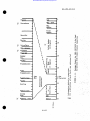
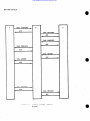
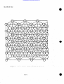
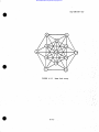
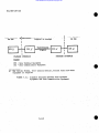
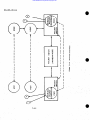
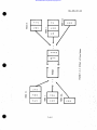
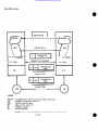
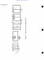
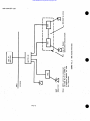
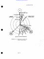
5.2.1 Generic Conf igurat ion.
In order to serve as a guide in DCS
transition and long-term planning, a generic configuration has been
defined as shown in Figure 5.1. The details of the configuration
are subject to change, but the general arrangement of elements
illustrates present DCA concepts for the DCS of the 1990’s, assuming
5-8
Downloaded from http://www.everyspec.com
MIL-STD-187- 310
logical extensions of ongoing DCA programs described in paragraph
5.1. Figure 5.1 is a functional diagram, and certain of the separate
functions shown could be combined for implamentat ion. The topology
of the future DCS could change significantly over the next 10 to 20
years, taking advantage of evolving technologies. In particular,
those ideas discussed in paragraph 5.3 are being evaluated at DCA for
possible recommendation at a later time.
Figure 5.1 illustrates the interrelationship of subeystem elements
within consolidated areas and backbone switching centers. A consolidated area is a geographically small access area that has a sufficiently
dense subscriber population to justify the use of concentrators (e.g.,
PBX’S, ~~’S,
CAP’S). Isolated terminals served by switching centers
are also shown. The configuration of Figure 5.1 is only an example;
not all of the elements will be located in every consolidated area or
in every backbc,ne switching center.
●
Clear voice terminals within consolidated areas will be connected to PBX’S, normally in an all-analog format. PBX’S will be
connected to the DCS via A/D interfaces (ADI’s), which will provide
the interface between the analog clear voice in the loops and the
nominal 16 kb/s clear voice in the DCS backbone. Digital PBX’s called
DAX’s will provide concentration and local circuit switching for digital
subscribers when a sufficient number of subscribers exist within a
consolidated area. Digital access circuits between concentrated areas
and backbone switching centers will normally be encrypted by trunk
encrypt ion devi.cee. Some consolidated areas will be connected to
umre than one backbone switching center to satisfy survivability/
reliability requirements. Isolated clear voice terminals will be
connected over analog access lines to ADI’s at backbone circuit
switches, or they will perform their own A/D conversions and be connected directly to backbone circuit switches.
Secure voice terminals will contain their own A/D devices and
key g enerators, and will be connected over digital loops to DAX’S in
consolidated areas, or over digital access circuits to backbone circuit
switches. When more economical, secure voice may be handled via protected transmission within a local area until concentrated via pooled
A/D equipment. Key variables for secure voice calls to allow end-toend encryption on a call-by-call basis will be provided by the key
distribution centers (SDC’e) located In the backbone switching centers.
Secure voice traffic will utilize the same backbone switching and
transmission facilities as the clear voice traffic.
5-9
Downloaded from http://www.everyspec.com
MIL-STD-187-31O
Data terminals may or may not utilize terminal key generators,
depending on their applications. Figure 5.1 shows data terminals
connected to communications access processors (CAP’s), which convert
serial bit streams into packets for switching by one or more backbone
packet switches. Some types of data, such as bulk data, may be more
suited to circuit switching than packet switching. Bulk data will be
entered through ports on secure voice terminals, through CAP’s, or
through multimode terminals. In the case of a multimode terminal,
either circuit- or packet-switching can be selected at the terminal, or
automatically by the communications selector switch (CSS). Studies
are currently under way to determine whether KDC’s should be utilized
by data terminal key generators to allow the desired end-to-end
encryption of data traffic.
Facsimile terminals in consolidated areas will be connected to
Isolated
CSS’s, to DAX’s, or to CAP’s depending on their applications.
terminals will be connected either to backbone circuit switches or to
CAP’S.
The record service canter (RSC) will provide the same service
features to narrative/record users of the future as provided by the
AUTODIN switches of today. Narrative/record terminals will be connected either directly to the RSC’s or to LDMX’s (local digital message
exchanges) which are In turn connected to the RSC’s; in either case,
the connecting circuits will normally be derived by packet switching.
In locations served by a CSS, connecting circuits may be provided by
circuit switching. Low-speed narrative/record terminals will in many
cases utilize low-bit-rate circuits derived by submultiplexing the
16 kb/s basic telecommunications channel. Submultiplexed circuits
will normally be nonswitched access circuits ; where remote CAP exists
in a consolidated area, the CAP performs a buffering and concentration
function as an inherent part of its normal packetizing function.
Narrative/record terminals might utilize KDC 1s to provide end-to-end
~ncVptio* between terminals
encryption, or they raight use only ll~ink!,
and LOMX’S, terminals and RSC’s, or LDMX’s and RSC ts.
Other typea of traffic, such as imagery and television, will
normally be carried by special purpose circuits.
The concept of system control for the future DCS is one of
localized control, centralized management, and operational direction
by exception. Primary responsibility for real-time control decisions
resides locally at a set of control centers called major control centers.
A major control center (not shown in Figure 5.1) wilI typically be
required for each 16 tech control or patch and test facilities (TCF/PTF),
for every 300 circuits, or for a combination of the two. Higher control
levels will be notified of any major control actions taken, will be
5-1o
0
Downloaded from http://www.everyspec.com
MIL-STD-187-31O
I
I
..
able to monitor the consequences of these actions, and, if required,
will be able to override these actions. Figure 5.1 shows a PTF in
the concentrated area and a TCF at the backbone switching center;
however, that allocation is not rigid.
The backbone switching centers will contain all of the backbone
switches in a given locality. Some switching centers will contain only
one or more backbone circuit switches (including the ADI function) .
Snme will contain both backbone circuit switches and one or more
packet switches, and others will contain, in addition, a record
service center. Individual switches within backbone switching centers
will be separated sufficiently to achieve satisfactory system surviability.
Many consolidated areas will contain only a PBX, an ADI, ,
and a DAX, in which case multimode terminals would not exist , and data,
narrative/record, and facsimile terminals would either utilize
dedicated or circuit-switched access circuits. Dedicated circuits
UtiliZatiOII
would be s“bmultiplexed as appropriate to msintain circ Uit
efficiency.
The transmission subsystem for the.future DCS will be primsrily
digital in nature, except possibly for clear voice or protected secure
voice local loops. Modems or analog-to-digital (A/D) converters will
ba used on any residual analog transmission segmsnts. Most of the
future DCS transmission needs will centhue to be provided by common
carriers, under tariff, and by government-owned or leased transmission
facilities. Transmission in CONUS and worldwide will uae the secure
mice bit rate as the basic digital channel; however, some access circuits”
and interswitch trunks for packet switching msy operate at higher or
lower bit rates within tbe multiplsx’ hierarchy [a].
.’
‘..
.,-.
.,”
‘-
,..
..,’
5.2.2 Switching Subsystem Elaboration.
Switcbing subsystems in the
future DCS will consist of the various functional switching elemenca
described in paragraph 5.2.1, with the topological arrangement
illustrated by Figure 5.1. This paragraph is divided into backbone
and access area switching and presents functional, hardware/software,
and O&M considerations for each,
.
; ..
i
5.2.2.1 Backbone Switching. Backbone switches will normslly be grouped”
.:~. .’:.,
,.,..
into backbone switching centers, with one or more BCS’s (backbone
circuit switches) , possibly a BPS (Backbone Packet Switch), and possibly
‘ ~ “ “.
an RSC (Record Service Center) . Switches within a backbone switching
.’,.,’
center will be’ physically separated for survivability enhancement.
ECA studies have estimated that in CONUS the future DCS switch quan.
,.’ ‘.
titles will be 43 BCS’S, 24 BPS’s, and 4 RSC’S, with 43 switching
:. ,.
centers. In Europe, the tentative quantities are 16 BCS “s, 3 BPS’s,
.~~ “’
and 2 RSC’s, w:ith 16 switching centers. In the Pacific, the tentative
‘j
. ,.
.
quantities are 9 BCS ‘s, 4 BPS’s, and 2 RSC’s, with 4 switching centers
~~~~
5-11
,,.
.
.
Downloaded from http://www.everyspec.com
MIL-STD-187-31O
(some with more than one BCS).
ewitch types follows.
A discussion of each of the backbone
5.2.2 .1.1 ~.
The Backbone Circuit Switch will switch clear voice,
secure voice, and circuit-switched data. Service features will include
multi-level precedence and preempt ion (MLPP), confere.ncing, call forwarding, compressed ksying, off-hook service, and others. Some
features may not be implemented at all BCS’s. Within CONUS, BCS’s
are expected to be modified ESS #1 switchee. Overseas , AN/TTC-39
svitches are to be used to assure Interoperability with tactical
telecommunications, and to facilitate implementation of the JMTSS
concept as required. ESS #1’s or TTC-39’s may be replaced with
other switches by the mid-1990 period of the future DCS, but a decision
on that need not be made for several years.
5.2.2 .1.2 ~.
The Backbone Packet Switch will normally switch interactive, query response, narrative record, and some bulk data traffic.
The BPs will receive packets from CAP’s or other BPS’s, perform format
and error checks, possibly perform additional eervice functions, and
forward packets to other BPS’s or destination CAP’s, as appropriate.
In addition to the CAP’s located in high density subscriber areas, other
CAP’s will generally be collocated with a BPS; in fact, the likelihood
is that CAP functions (see paragraph 5.2.2.2 on access switches) will
be built into the BPS, resulting in an integrated and inseparable
BPS/CAP .
e—
5.2.2 .1.3 ~.
The Record Service Center will provide the same service
features to narrative/record users of the future as is provided by
AUTODIN switchee today. RSC’S will utilize hardware with lower 06M
requirements than today’s AUTODIN switches, and they will be located
in the vicinity of BPS’s and BCS’s in order to further minimize O&M
and manning requirements. Within CONUS, where RSC’S, BPS’s, and BCS’S
might be operated by two or three different contractors, these OfaM
wavings may not be realized. An effort needs to begin now to determine
how the three types of switches can realize the same sort of O&M
savings that are anticipated for government-owned backbone switching
centers overseas.
5.2.2.2 Access Switching.
The access area switching elements shown
in Figure 5.1 for the future DCS are the PBX (Private Branch exchange)
and associated analog/digital interface unit (ADI), the DAX (Digital
Access Exchange) , the CAP (Communications Access Processor), the CSS
(Communications Selector Switch), and the LDMX (Local Digital Message
Exchange) .
5.2.2 .2.1 ~.
The primary function of the PBX will be to interconnect local clear voice subscribers, to connect them to the DCS
5-12
.
Downloaded from http://www.everyspec.com
MIL-STD-187- 310
backbone, and, in most cases, to other telephone systeme such as local
common carriers. The PBX function will usually be automated, making
it a PABX (Private Automstic Branch exchange) . Operator assistance
will often be available at PABX’s; however, an attempt should be made
to automate as many operator functions as possible to minimize 06M
costs. PBX service options may include such features as inward and
outward MLPP (Multi-Level Precedence and Preemption) , call forwarding,
confersncing, abbreviated dialing, etc. The TRI-TAC version of the
PBX will be called the ULS (Unit Level Switchboard). It is sxpected
that PBX operation will continue in the analog mode, with POS sible
except ions in tactical areas. Conversion of clear voice from analog
to digital will normslly take place at the ADI (Analog Digital Interface) in consolidated areaa, or at the ADI in backbone switching centers.
Secure voice and circuit-switched data wfll be concentrated at tbe DAX
rather than at the PBX. At some locations, the functions of the AOI
and the DAX (or even the PBX) IMY be combined into a single switchfng
element, and in most cases tbe O&M for the PBx, ADI, and the DAX should
be combined in order to minimize msnning and O&M costs.
5.2.2.2.2 ~.
●
The DAX provides tha digital-subscriber interface with
the DCS. It provides local switching for digital traffic (secure voice,
snd circuit swftcbed data), it msintains a local time source, and it
serves to Interconnect local secure voice, circuit-switched data,
facsimile, and possibly clear voice traffic to tbe DCS backbone.
It
also serves as a restoral path for packet-switched data traffic. As
stated above, tbe DAX could be a separate switching element or integrated
with the AD I and possibly the PBX; in any case, all three should normally
be located in close proximity so that O&tl can be handled on an integrated
basis. DAX Oh!.1should also be unified with that for the CAP, the CSS,
and possibly the LDMX. This integrated 06M is the only way to justify
some of these switching elements (i.e. , the CAP and the CSS) from a cost
consideration.
5.2.2 .2.3 LDMX. The LDMX does for record traffic what the PBX does for
clear voice=
fflc. The LDMX receives and distributes messages from
and to local narrative/record terminals. It also provides recordkeeping,
automated routing, and facilities to simplify tha pessage release/
approval function. The LDMX provides the intercon~ection betwean
consolidated-area narrative/record terminals and the RSC (Record
Service Center). The RSC provides the same function as the AUTODIN
switch of today. LDMX’S will not be located in all consolidated areas,
and service features will vary from one LDMX to another. Where used,
,
however, the LDMX should greatly reduce the writer-to-reader time of
record traffic from that of the current ADTODIN system. Tbia interconnection can either be by direct access line, tbrougb tbe packetswitched subnetwork (the CAP and BPS (Backbone Packet Switch)) , or
through the circuit-switched subnetwork (the DAX and the BCS (Backbone
5-13
Downloaded from http://www.everyspec.com
MIL-STD-187-31O
Circuit Switch) ). At some facilities, the CSS will make the decision
whether to use the CAP/BPS or the DAX/BCS route. The LDFfSO&M should
be integrated with that of other consolidated-area switching facilities
to the maximum extent practical in order tn reduce manning/OLM costs.
5.2.2.2.4 ~.
The CAP provides interconnection of consolidated area
data traffic to the BPS (Backbone Packet Switch); the CAP serves as
the interface with the packet-switched subnetwork. Interactive, query/
response, and narrativelrecord traffic can normally be served more
efficiently by the packet-switched subnetwork than the circuit-switched
network as conceived for the future DCS. This is true because the CAP
serves as an efficient concentrator, interspersing traffic from various
low-speed subscribers into the same bit stream, thereby serving as a
The w
has an advantage over the submultiplexer,
virtual “submultiplexer.”
however, in that it is not restricted to any specific multiplex hierarchy
other than nominal multiples of 2 kilobits, and the 2-kilobit segments
(packets) are only used for any given subscriber when they are actually
“ceded to transmit data. The access circuit between the CAP and the
BPS can operate at fixed bit-rate within the 8000N multiplex hierarchy
of the future DCS. The CAP/.DAX/BCS/BPS path can be used for augmentation or restoral in increments of 16 kbls. Bulk data traffic can
utilize either the circuit-switched or tbe packet-switched subnetwork,
depending on the need for error correction, the relative loads in the
circuit and packet subnetworks, and the characteristics of the bulk data
(e.8.. quantity, precedence. data structure, desired transfer rate).
The 06M for the CAP will normally be combined with that for other consolidate
ed area switthing elaments.
.0
The CSS function is to facilitate the selection of
5.2.2 .2.5 ~.
circuit switching or packet switching for bulk data and narrative/record
traffic. Facsimile, graphica, and multipurpose terminals may also be
connected to the CSS. The CSS could also seine as an automatic restoral
device, routing CAP traffic into the DAX or DA2i traffic into the CAP.
Packet switching could potentially be used to provide voice restoral,
with only modest degradation; e.g. , a 1 or 2 second time lag in each
direction. The decision on using circuit switching or packet switching
for a given type of traffic will be made at the terminal or at the CSS.
Selection at the CSS will normally be based on network status. The CSS
will probably not be located at all consolidated areas , but it cam be
installed when and where needed to improve the efficiency of circuit
utilization. OSM for the CSS should be combined with that for other
switching elements in the acceas area [al.
5.2.3 Plaming Standards Requirements. In ,order to dete~ine the
areas in which switching planning standards are needed, it is necessary to trace the changea planned for the DCS in the switching area
and the major design decisions required to implement these changes.
I
5-14
@
Downloaded from http://www.everyspec.com
MIL-STD-187-31O
5.2.3.1
Overseas DCS
5.2.3.1.1 -.
Implementation of a DCS-suitable version of the
AN/TTC-39 is planned. for the early to mid-19 S0’s, to replace the overseae AUTOVON switches. A review of the switch design was made and a
number of design changes have been identified which must be made before
the AN/TTC-39 can be effectively used in the DCS [h]. Required
changes have been submitted to the TRI-TAC Office In a series of WA
Engineering Change Proposals (ECP’s). These ECP’S, the most recent Of
which is reference [c], have been technically approved by the TRI-TAC
Configuration Control Board (CCB). Reference [b] also identifies
aspects of the AN/TTC-39 performance requiring further analysia. These
are:
a.
Forecasting DCS traffic flow under a TTC-39 awftched DCS ta
evaluate switch and network sizing and connectivity.
b.
Investiga ting interface arrangements between the TTC-39 time
division matrix (TIX4X),and DCS terrestrial and DSCS transmiesiOn
facilities. Also, investigating synchronization of the TTC-39
with digital channels or trunk groups.
c.
Specifying DCS s~tem
AN/TTc-39 .
d.
Developing common format standards for Common Channel
Signaling (CCS).
e.
Investigating performance of repeated AID conversions
with tandezued conference bridges.
f.
Invest igating provisions required for zone restrictions.
g.
InvestIgating the capability for replacing Space Division
Matrix (SDMX) modules with Time Division Matrix (TDMX) modules to
accommodate transition to an all-digital DCS.
h.
Evaluating the problem of interoperabilit y be tveen a
16 kb/s DCS TTC-39 and a 32 kb/s tactical TTC-39. Included
is the problem of transitioning from a 16 kb/s CCS TTC-39 to
a lower rate DCS switch.
i.
Investigate the desirability of the TTC-39 having single channel
interface rather than interface interswitch trunk groups on a
group basis.
control elements to interface with the
5-15
“‘ ,.
Downloaded from http://www.everyspec.com
MIL- STD-187- 310
j.
Investigate interface arrangements with lower level digital
exchanges.
k.
Identification of unique equipment that the DCS must provide.
1.
Identification of procedures to handle secure voice enclaves.
5.2.3
.1.2
The DCS AUTODIN, currently operational, will be
~.
retained to provide classic store and forward (S/F) narrative and DAT’APATTES?li
message traffic c.spability as may be required subsequent to the
implementation and cutover to operation of the AUTODIN II packet switching centers. Implements tion of AUTODIN II will provide additional data
services in the DCSto meet record communications and teleprocessing
needs. This subsystem will be the first step in achieving a unified
data switching subsystem. Each AUTODIN I ASC will be connected to an
AUTODIN II switch as a host subscriber. The AUTODIN II subsystem will
provide the backbone trunking for the ASC’s. The data switches, in
addition to packet switching, will provide packetizing of the data, line
scanning for switch channels, interim storage during error checks and
routing. call signaling to the backbone switch, routing tables, traffic
nwnitoring and control, distribution of multipackets to multichannel,
and error control. AUTODIN II switches will require only minimal hardware development; axisting computers or minicomputers can be used, with
the design consisting nainly of system engineering and software development. The primary problems during the transition from AUTODIN I to
AUTODIN 11 will be the maintenance of satisfactory software interface
(i.e., protocol) between AUTODIN I subscribers and the AUTOD2N II
packet xwit=h, and the satisfaction of the transmission and switching
requirements of the Worldwide Military Command and Control System (WWMCCS)
and of dedicsted users being absorbed into the system. It is planned
that AUTODIN II will be provided as a leased or tariffed service in
Experience from this subsystem as well as results
the CONUS (PffASEI).
of related SDT&E will be used to refine the design prior to expansion
of the CONUS system and implementation of a government-owned system
overseas (Phase II) . A systam specification for AUTODIN II, Phase I
has been developed [d]. The specification defines the network topology,
routing, addressing and numbering, codes, protocols, error control,
craffic flow control, system and network control, security provisions,
electrical interfaces, switch architecture, processing requirements,
and software requirements.
It also covers traffic statistics, the
subscriber types and their modes of information transfer, the speed
and quality of service, and the operational relationships of AUTODIN II
with other DoD networks and systsms. AUTODIN I subscribers will not
be impacted in any way under AUTODIN II (Phase I) arrangements. Therefore, initially, AUTODIN I functional, operational, and performance
aspects will remain as presently defined. Although the specification
for AUTODIN 11 has been developed , all aspects (i.e., system, network,
5-16
9
Downloaded from http://www.everyspec.com
MIL-STD-187- 310
subsystem, equipment, and interface designs ) must be conf inned by
development, test, and evaluation. Key items in the switching area are:
a.
Addressing/numbering plan
b.
Internal netwnrk and network-to-user protocols
c.
Segment and packet design
d.
Line control procedures
e.
Error control
f.
Switch internal architecture
g.
Software subsystems
h.
System control aspects
i.
Interface arrangements including procedural and
electrical interface with various modes of AUTODIN I and
other DoD data netwnrks
j.
Switch size tradeoff. Development of a small, modular,
expendable AUTODIN II switch may be the most coat-effective
solution to satisfy requirements.
k.
Development and fielding of KDC equipment for the data network.
... .
.,
5.2.3.1.3 ~ecial Services. Special services will include wideband
facsimile, television and imagery. The primary users of wideband
These services
services will be WWMCCS and intelligence systems.
will be carried over the switched networks, or over dedicated networks
if necessary, and require an average of 1 Mb/s capacity per circuit.
The DSCS has the capacity and long-haul capability to provide these
special services as dedicated links under DCS management. Present
plans are to provide wCCS
with a global satellite capability via
the DSCS Phase II and Phase 111 satellite systems. Aspects of the
DCS special services program that require further analysis are:
a.
.,,
Role of varying wideband user demands in an integrated
switched environment
b.
Control and signal structure compatibility between DSCS
demand assignment modems and the switching networka
c.
Implicat ions of packet switching when applied to varying
satellite multiple access alternatives
... .,
,’
-.. .
.,
., .,.,,
5-17
,.
Downloaded from http://www.everyspec.com
MIL-STD-1S7-31O
,
d.
In band/out of band control between switching networks and
satellite earth terminals that maintain the bit integrity,
tra[fic flow, security and synchronism of user-to-user
encrypted data
e.
Effects of error control and switchinglpower transients on
user compressed data.
●
5.2.3.1.4 Access Area.
A design goal for more efficient use of
transmission capacity and backbone switching is to provide traffic
concentration and switching in the access area. The favorable cost
of switching compared to transmission, and the operational advantages
of dynamic control and allocation of transmission capacity, foster
increased use of local area switching and concentration of traffic for
the DCS. Access area concepts are discussed in paragraph 5.1.2.2;
however, system level design of the access area as an integrated subnetwork remains to be accomplished. Design requirements include
specification of the following:
a.
Subnetwork featurss such as topology, routing, traffic
flow, etc.
b.
Allocation of functions lfeatures among the backbone
switches, access area switches and facilities, and terminals
c.
Access area switch and facility designs
d.
Interfaces between backbone switches, access area switches/
facilities and terminals in regard to signaling and supervision, circuit and signal characteristics, etc.
.’9.
5.2.3.2 CONUS DCS’
5.2.3 .2.1 Clear Voice. Since the policy of leasing backbone facilities
from commercial carriers in CONUS is not expected to change, the
principal options for achieving digital clear voice switching are to
modify the present CONUS switches to a digital configuration, or fund
for carrier development of a new digital switch which in turn would be
leased. Implementation of digital clear voice will be governed by
commercial network transition to digital service and the economic competitiveness of digital service to analog service. Although digital
transmission capability may be expanded, it is unlikely that clear
voice will be digitally switched prior to 1990. Local area concentration and AID conversion would be accomplished as discussed in paragraph 5.2.2.2.
5-18
0’
Downloaded from http://www.everyspec.com
MIL-STD-187-31O
5.2.3.2.2 Secure Voice. Implementation plans for secure voice in the
CONUS require modification of selected AUTOVON switches for 16 kb/s
digital operat:io” (Including digital signaling) . In order to provide
this additlonal capability, it is necessary to :
a.
Establish digital trunk and loop signaling plans.
b.
Consider any modifications needed to the numbering plan
for secure voice calls.
c.
Determine service features to be provided secure voice
subscribers.
d.
Modify switches to handle 8/16 kb/s bandwidth and processing
speed; detect, interpret, and processing digital signaling;
and process clear-to-secure connections involving AfD voice
and signal ing conversion.
e.
COMSEC features applicable to the switch, to be included
in a Secure Communications Planning Standard, will cover
characteristics/techniques applicable to:
(1)
Electronic key distribution
(2)
Secure call placament procedures
(3)
Crypto synchronization modes.
5.2.3.2.3 Data.
S/F service will continue to be provided by AUTOD2N.
Interactive=~a
service will be provided on a dedicated basis through
a lease or tariff service. The packet-switched subnetwork will be
integrated w+th the eight tariffed CONUS AUTODIN I switches. l%is subsystem will be a vehicle for confirming/revising design decisions
prior to implementation of the AUTODIN II, Phase II. (See paragraph
5.2.3 .1.2.)
5.2.3 .2.4 Special Services. The discussion in paragraph 5.2.3 .1.3
pertaining to special services in the overseas DCS also appliea
essentially to CONUS DCS. Also the Washington Area Wideband Communications System (WAWCS) will interface Washington, D. C. metropolitan
users requiring special services with the appropriate switching networks.
5.1.3 .2.5 Access Area. The discussion in paragraphs 5.2.2.2 and
5.2.3 .1.4 pertaining to the access area in the overseaa DC S alao
aPPlies, essentially, to the CONUs DCS.
5-19
,..
Downloaded from http://www.everyspec.com
MIL-STD-187-31O
5.3 The Future DCS - Advanced Concepts
5.3.1 Overview. In paragraph 5.2 the nominal future DCS was defined
in a number of key areas; however, several aspects of the future system
remain either very broad in their definition, or not fully delineated.
Ibis paragraph addresses these aspects and some specific choices that
need to be examined. Most basic of these is the general architecture
which the future system will follow. The nominal future DCS described
in paragraph 5.2 still retains an overall structure very similar in
form to the present system. As discussed in paragraph 5.2 a number of
significant improvements in the DCS now being planned (e.g., Phase II
Secure Voice, AUTODIN II, digital transmission upgrades) will have
been implemented by the mid-1980’s. These modifications are being
planned as evolutionary changes to subsystem elements, and do not
represent significant departures from the present DCS structure.
Although more fundamental changes may occur their exact nature cannot
be predicted, precluding a plan or program for implementation. Both
technical details and time phasing are highly conjectural at this time.
The concepts discussed in this overview, or any variations ultimately
proved to be cost-effective, could lead to a system structure with the
following features:
a.
Increased installation of satellite terminals associated
directly with individual access areas - emphasizing direct interconnectivity between access areas via satellite, and reemphasizing
connectivity via the terrestrial backbone transmission and
switching structure, with its physical rigidity and OSM overhead
burden,
b.
Use of a single, integrated structure for switching and multiplexing of voice, data, and other traffic - either by
packet izing all traffic, or by using computer technology to
achieve a real-time dynamic allocation of wideband transmission among varying traffic rates and service requirements.
c.
Movement of DCS switching nodes closer to the main frames a logical extension of greater use of satellite communications
and integrated switching.
d.
Diminishing visibility of tactical/strategic and user/system
interfaces in a highly flexible, satellite-oriented environment trending toward a more unified DoD network.
Some will judge that these changes are at least 20-30 years in the
future, if desirable at all, while others may think that such changes
can and should be substantially begun within the next 5 to 10 years.
They are included in this planning standard to identify them aa
potential changes, so that sufficient R&D efforts are initiated [a].
5-20
.
. .
a
Downloaded from http://www.everyspec.com
MIL-sTD-187-31O
5.3.2 Switch inK Subsystem Elaboration and Planning Standards
Requirements. A design goal for the future digital DCS is to have
common switching and transmission facilities to service all modes of
traffic, including video and facsimile. A common or unified switch,
as described in Chapter 10, mixes tbe multiplexing and switching
functions and permits “dynamic” allocation of transmission capacity,
instead of providing an end-to-end connection for a call and providing
this connection over a standard (i.e. 4 kHz/8 kb/s) channel. Unt11
an efficient unified switch is developed, however, the DCS will continue to employ different switching techniques to meet various subscriber requirements. Planning standards (which also include
undefined characteristics) are required in the following areas:
a.
Anticipated traffic handling requirements; i.e. , types of
traffic, arrival rates, holding times, traffic flow, etc.
b.
Functional description
c.
Performance characteristics
d.
Switch internal architecture
●
e.
.,.
.’.
(1)
processing, and control elements
(2)
Storage
(3)
Input/Output
.
,:,
Interface design,
5.4 Areas Deserving Special Emphasis. In previous paragraphs, various
optional arrangements were identified which require specification for the
evolving and future DCS. Several of these daserve special consideration and are highlighted or noted in the following paragraphs.
5.4.1 Signaling and Supervision. During the 1976-1986 time period
new signaling schemes will be introduced into the DCS. Nhen the
AN/TTC-39 is introduced overseas, in addition to the present AUTOVON
signaling, there will be common channel signaling (CCS) on trunks and
either in-band or out-band digital signaling on access lines depending
on access line cross section. CCS and digital access line signaling
are also under consideration for the CONUS DCS. It is important that
signaling schemes for the access area and the access area to backbone
switch are compatible, and that CONUS and overseas versions of interswicch trunk signaling are interoperable. A similar case can be made
for line control and signaling formats for data. In addition, the
possibility of a future unified switch (wherein all modes of traffic
.,
.
..
.
,,
.,
,’
“~,~
‘
“
.,
5-21
,:.
.
Downloaded from http://www.everyspec.com
MIL-STD-187-31O
could have common call setup procedures, common methods of line control, signaling, addressing, etc ., and common codewords and formats)
needs to be considered in the design of signaling plans to permit
evolution to a future unified signaling system.
5.4.2 System Control. A separate system control planning standard
5.sto be developed. However, those aspects of system control which
affect ~“itch design need tO be addressed in the switching planning
standard. This includes specification of the parameters to be
monitored , control actions to be taken , and methods of implementation
(hardware/software) .
.5.4.3 Secure Communications. A separate planning standard on secure
communications is to be developed. However, those aspects of secure
communications which affect switch design need to be addressed in the
switching planning standard. This includes characteristics discussed
under paragraphs 5 .2.3.1.1 and 5 .2.3.2.2 for secure voice, and security
level access protection and other security safeguards required for the
AUTODIN II switch.
5.4.4 Interoperability. The need for the DCS to interoperate with
other DoD and non-DoD systems must be considered in planning standards
development. Therefore, the specification of characteristics and
parameters to be included in the planning standards must be done in
full consideration of present specifications and future plans for the
TRI-TAC system, commercial systems (both national and international) ,
and NATO /NICS. Also, consideration must be given to the FixIalReport
of the Committee on Interoperability, and DoD, national, and international communications system standards.
5.5 Summary of Planning Standards Requirements . In view of the foregoing, switching planning standards are needed as follows:
a.
Specification of DCS requirements, including both clear and
secure voice, for the ANITTC-39. In addition, numbering plan,
service features, and signaling and supervision must be
specified to ensure compatibility with the tactical AN/TTC-39
and the U. S. commercial system.
b.
Specification of CONUS Phase II Secure Voice requirements to
include modification of AUTOVON switches, numbering plan,
signaling plans, and service features.
c.
Specification of all elements in the access area and the interface with the backbone switches.
d.
Specification of AUTODIN 11 switching. Addressing, protocols,
segment and packet design, and line control procedures must
Q
Downloaded from http://www.everyspec.com
MIL-STD-187-31O
be specified considering the need to satisfy UWMCCS requirements and assure compatibility with SATIN IV and other
dedicated users to be absorbed into the system.
5.6
e.
Specification of Systam Management and Control procedures,
operation and maintenance aspects.
f.
The switthing planning standard should be struttured to
accommodate technical data, as it becomes available, on:
(1)
A future unified switch capable of switching all modes
of traffic
(2)
Software, including a communications-oriented Higher
Order Language (HOL) .
References.
[a]
DCEC TR 14-75, “Engineering Concepts for the Future DCS” (U),
JUIY 1975 (sECRET).
[b]
DCEC TR 20-74, “Technical Review of the AN/T”TC-39 for Use in
the DCS” (u), August 1974 (CONFIDRNTLIL).
[c}
DCA (Code 410) letter to Director, Joint Tactical Communications Office, subject: fiodification of Engineering Change
Proposal (ECP) DCA 003R3, 20 Novamber 1974, 19 March 1975.
[d]
DCA System Perform.ance Specification (Type “A”) for
AUTODIN II, Phase 1, Novamber 1975.
,..
5-23
.
Downloaded from http://www.everyspec.com
MIL-STD-187-31O
CHAITER 6
CIRCUIT SWITCHING
CONTENTS
~
6-1-1
SECTION 1 - NUMBERING PIAN
Paragraph 6.1.1
6.1.1.1.
6.1.1.2!
6.1.2
6.1.2.1.
6.1.2.:!
6.1.2.3
6.1.2.4
6.1.2 .4.1
6.1.2 .4.2
6.1.2 .4.3
6.1.3
6.1.4
6.1.4.1.
6.1.4.;!
6.1.5
6.1.5.1.
6.1.5.:!
6.1.5.3
6.1.5.4
6.1.6
Introduction
Purpose
Scope
Numbering P1an Format
Precedence Codes
Special Feature Codes
Escape Codes
AtidressDigits
Area Codes
Switch Codes
Line or Station Numbers
Subscriber Dialed Instructions
Interswltch Numbering System
Interswitch Numbering Between
Digital Switches
Interswit ch Numbering Between
Analog and Digital Switches
Interface
Tactical
NATO
Store and Forward
Commercial
References
6.2.2.1.
6.2.2.;!
6.2.2 .2.1
6.2.2 .:!.2
6.2. 2.~!.3
6.2.2.:!.4
6.2,2.3
6.2.2.4
6-1-13
6-1-13
6-1-13
6-1-13
6-1-13
6-1-13
6-1-16
6-2-1
SECTION 2 - SERVICE FRATORBS
Paragraph 6.2.1
6.2.2
6-1-1
6-1-1
6-1-i
6-1-2
6-.1-2
6-1-2
6-1-4
6-1-4
6-1-5
6-1-5
6-1-6
6-1-6
6-1-10
6-1-10
Introduction
Service Features Selected
by the Subscriber
Precedence
Conferencing
Progressive Conferencing
Preprogrammed Conference
Meet-Me Conference
Application of Con ferencing
Call Transfer
Operator Access and Operator Recall
6-O-1
6-2-1
6-2-1
6-2-2
6-2-2
6-2-2
6-2-4
6-2-5
6-2-5
6-2-6
6-2-6
,,,
Downloaded from http://www.everyspec.com
MIL-STD-187-31O
CONTENTS - Continued
Paragraph 6.2.2.5
6.2.2.6
6.2.2.7
6.2.2.8
6.2.2.9
6.2.2.10
6.2.3
6.2.3.1
6.2.3.2
6.2.3.3
6.2.3.4
6.2.3.5
6.2.3.6
6.2.3.7
6.2.3.8
6.2.3.9
6.2.3.10
Call Hold
Abbreviated Dialing
Compressed Dialing
Trunk Access
Data Service
Direct Access
Predetermined or Network
Service Features
Preemption
Line Grouping
Mul tiline Terminals
Zone Restriction
Community of Interest
Traffic Load Control
Bridging
Trouble Response
Intercept
Secure Ca 11 Mode/Key Conversion
6-2-7
6-2-7
6-2-S
6-2-9
6-2-9
6-2-10
6-2-10
6-2-10
6-2-11
6-2-12
6-2-12
6-2-12
6-2-13
6-2-13
6-2-14
6-2-14
6-2-14
SECTION 3 - DIGITIZED INFORMATION TONES AND RECORDED ANNOUNCEYf~TS 6-3-1
Paragraph 6.3.1
6.3.2
6.3.2.1
6.3.2.2
6.3.2.3
6.3.2.4
6.3.2.5
6.3.2.6
6.3.2.7
6.3.3
6.3.3.1
6.3.3.2
6.3.3.3
6.3.3.4
6.3.3.5
6.3.4
Introduction
Information Tones
Dial Tone
BUSY Tone
Error Tone
Ringback Tone
Nonsecure Warning Tone (NSWT)
Conference Disconnect Tone
Ring Signal
Recorded Announcements
Authorized Precedence Exceeded
Restricted Area Call
Unassigned Number
Temporarily Out of Service
Conference Notification
References
6-O-2
6-3-1
6-3-2
6-3-2
6-3-2
6-3-4
6-3-4
6-3-4
6-3-4
6-3-5
6-3-5
6-3-5
6-3-5
6-3-5
6-3-5
6-3-6
6-3-6
9
Downloaded from http://www.everyspec.com
MIL-STD-187- 310
CONTSNTS - Contin.ed
?sss
SECTION 4 - SIGNALING AND SUPERVISION
Paragraph 6.4.1
6.4.2
6.4.2.1
6.4.2.1.1
6.4.2.1.2
6.4.2 .1.3
6.4.2 .1.4
6.4.2 .1.5
6.4.2.1.6
6.4.2 .1.7
6.4.2.2
6.4.3
6.4.3.1
6.4.3.2
6.4.3 .2.1
6.4.3 .2.2
6.4.3.3
6.4.3.4
6.4.3.5
6.4.3 .5.1
6.4.3.5.2
6.4.4
6.4.4.1
6.4.4.2
6.4.4.3
6.4.5
6-4-1
Introduction
Interswitch Trunk Signaling
and Supervision
DCS Overseas S/S
Common Channel Signaling Equipment
Trunk Message Formats
Message Sequences
Message Routing
Message Acknowledgment
‘Trunk Numering and Selection
Message Processing
CONUS DCS S/S
Access Line Signaling and Supervision
Interfaces
DAX To/From Digital Backbone Switch
Out-of -Band S/S
In-Band S1S
S/S Between DAX’S
DAX To/From Analog PBX
Direct ly Connected Digit sl Subscriber
To/From Digital Backbone Switch
DSVT Signaling in OVerSeaS
DSVT Signaling in CONUS
Loop Signaling
Digital Loop S/S
Analog User on the DAR
Analog LooP S1S
References
6-4-2
64-2
6-4-5
6-4-11
6-4-13
6-4-14
6-4-15
64-16
6-4-21
6-4-22
6-4-22
6-4-22
6-4-22
6-4-23
6-4-23
6+2 3
6-4-23
6+-23
6-4-24
6-4-24
64-25
6-4-25,
6-4-25
6-4-25
6-5-1
SECTION 5 - ROUTING
Paragraph 6.5.1
6.5.2
6.5.2.1
6.5.2.2
6.5.2.3
6.5.2.4
6.5.3
6.5,3.1
6.5.3.2
6-4-1
6-4-1
Introduction
CONDS AUTOVON Routing
General Description
Routing Procedures
Route Control Principles
Precedence Rout ing
AUTOVON Routing
CNer SeaS
~“eral DascriptiOn
Routing Procedures
6-O-3
““
6-5-1
6-5-1
6-5-1’
6_5-1
6-5-4
6-5-4
6-5-7 :
6-5-7
6-+7’,’””
..
-
Downloaded from http://www.everyspec.com
MIL-STD-187-31O
0’
CONTSNTS - Continued
Paragraph 6.5.3.3
6.5.3.3.1
6.5.3 .3.1.1
6.5.3 .3.1.2
6.5.3.3.2
6.5.3 .3.2.1
6.5.3 .3.2.2
6.5.3.4
6.5.4
6.5.4.1
6.5.4.2
6.5.4 .2.1
6.5.4 .2.2
6.5.4 .2.3
6.5.4.3
6.5.5
6.5.5.1
6.5.5.2
6.5.6
6.5.7
Route Control Principles
Originating Office Control
Early Cut-Through
No-Early Cut-Through
Spill-Forward Feature
Spill-Forward Service
Treatment Indication
Spill-Forward from CONUS Gateway
to Overseas Gateway Offices
Precedence Routing
AN/TTC-39 Routing
Routing Procedures
Route Control Principles
Originating Office Control
Spil1 Forward
Traveling Classmarks
Precedence Rout ing
DAK Routing
Normal Routing
DAK-DAK Rout ing
Routing Methods for Future
CONOS Network
References
6.6.2.3
6.6.3
6.6.3.1
6.6.3.2
6.6.4
6.6.4.1
6.6.4.2
6.6.4.2.1
6.6.5 “
6.6.6
6-5-g
6-5-8
6-5-8
6-5-9
6-5-9
6-5-9
6-5-9
6-5-12
6-5-12
6-5-12
6-5-12
6-5-12
6-5-12
9
6-5-12
6-6-1
SECTION 6 - INTERFACES
Paragraph 6.6.1
6.6.2
6.6.2.1
6.6.2.2
6.6.2 .2.1
6.6.2 .2.2
6.6.2 .2.3
6-5-7
6-5-7
6-5-7
6-5-7
6-5-8
6-5-8
Introduction
Terminals
Clear Telephone Terminals
Secure Telephone Terminals
KY- 3
NBST (Narrovband Subscriber Terminal)
Digital Subscriber Voice
Terminal (DSVT)
Data Terminals
PBX
Backbone Switch to PBX
PBX to ADI to Backbone Switch
Trunks
Interswitch Trunks
Extraswitch ‘hunks
Digital Access Exchange (DAK)
Backbone Packet Switch to
Circuit Switch
References
6-O-4
6-6-1
6-6-1
6-6-1
6-6-2
6-6-2
6-6-2
6-6-2
6-6-2
6-6-2
6-6-2
6-6-2
6-6-2
6-6-2
6-6-3
6-6-3
6-6-3
6-6-3
:
,.
Downloaded from http://www.everyspec.com
MIL-STD-187-31O
CONTENTS - Continued
SECTION 7 - CIRCUIT SWITCH CSARACTERISTICS - OVSRSSAS
Paragraph 6.7.1
6.7.2
6.7.3
Introduction
Design Requir-ents
References
IT SWITCH CHARACTERISTICS - CONOS
SECTION 8 - C IRCII
6-7-1
6-7-1
6-7-3
6-8-1
6-O-5
.
Downloaded from http://www.everyspec.com
MIL-STD-187- 310
CHAPTER 6
CIRCUIT SWITCHING
SECTION 1
NUMBERING PLAN
6,1,1 Introduction. An essential element of local and long distance
dialing is a numbering systam wherein each subscriber has a unique
number which is convenient to use, readily understandable, and identical
in its format to that of all other telephones connected to the network.
With such a numbering system any subscriber, wherever located, may use
this system to reach the desired telephone anywhere in the world.
●
,.
....
,.
The current DCS numbering system has been derived from the commercial numbering system used by the U.S. common carriers and adopted
throughout most of the nations of the world. Therefore, the overall
numbering system which the DCS uses is an accepted standard throughout
the world, and future DCS plans should reflect our adherence to this
standard.
6.1.1.1 Purpoee,. The purpose of this document is to describe briefly
the numberine. svstam that will exist in the DCS In the time frame of
1979-1981 wh~n ~he Phase 11 secure voice program will begin to be
implemented. In this time period, modification for digital operation
will have begun on several existing CONUS AUTOVON (No. 1 ESS) switches
and TENLEY COMSEC equipment will be in the process of being introduced
into the modified switches. The introduction of the ANITTC-39 circuit
switches is also planned for approximately the 1980-82 time frame, so
that eventually they will replace all the axisting overseas AUTOVON
switches. In this time frame a new Digital Access Exchange (DAX) will
be introduced into the DCS to perform the local (low level) switching
and concentrating function in both CONUS and overseas.
.,
,. ...,,
.
-.;
..
..:,.
The numbering system described herein la applicable to
6.1.1.2 -.
circuit switched service originated by clear voice, secure voice, or
data subscribers.
Note that data subscribers may have a numbering system peculiar to
their own needs; however, when these subscribers need to place circuit
switch data calls, they will use the numbering system and dialing
instructions described herein to reach the distant end. Any additional
switching and routing necessitated by the data numbering system is not
Of a circuit switch nature, and is not covered by this paper.
,.
;.,
.,. .
-,. .
:
6-1-1
.
“.
Downloaded from http://www.everyspec.com
!4IL-STD-187-31O
Q
6.1.2 Numbering Plan Format. The numbering plan format to be used in
the DCS for circuit switched service will be made up of the following
parts which will appear in the order indicated:
PFEA,
where P is theprecedence code, F is the special features code, E is the
escape code, and A is the address i.nformction.
6.1.2.1 Precedence Codes. The precedence indicator is the first
element in the sequence and it will be the first element dialed by the
subscriber or user Al if he exercises his option for precedence routing.
A subscriber will be able to assign any precedence up to and including
the highest precedence authorized to him for any call which he attempts
to establish. The precedence indicators in order of decreasing precedence are:
FO - Flash Override
F
- Flash
I
- Immediate
P
- Priority.
The Routine (R) precedence is indicated by the absence of any other
precedence indicator at the start of the subscriber dialing sequence.
As noted above, the dialing of the precedence code ie optional; if the
precedence code is not dialed, Routing precedence will be aasumed by
the switch.
6.1.2.2 Special Feature Codes. Subscribers using the new types of
ewitches will have available to them a variety of special features based
on their claasmarks. These special features will be accommodated in
the numbering plan via special feature codes which the subscriber will
dial . The special feature code is optional and its absence will cause
the call to be treated as an ordinary voice call, contingent on the
subscriber~s classmarks. For example, a call from a eecure voice subscriber will be treated aa a secure voice call, even though a special
feature code for secure voice service was not designated and not dialed
by the originator. Table 6.1.1 indicates the codes used to request the
Al In general, a subscriber is a terminal connected to a No. 1 ESS or
AN/2TC-39 switch, and a user is a terminal connected to a DAX. As
used in this document, the term subacr iber will include capabilit lea
of both subscribers and users, whereas the term user will include
capabilities that are peculiar to those terminals.
6-1-2
o
Downloaded from http://www.everyspec.com
M1L-s’2D-187-31o
TASLE 6.1.1
SUBSCRIBSS DI.4L2D
Backbone
(Analog)
M-key
Lf
3N3OSMATION AI
Subscribers
(DVST)
16-key
j/
Prac ed ,“.,
m
Flash
Override
Flash
Immediate
Priority
FO
F
1
P
3’
I
P
Reserved
Prefix
~/
m
F
1
P
lxi
Co”fere”ce.
Progressive
l“itiace
Release
>1
Wmns”er,d
A + Addraee
A
C + Addreae
c
6.4 w
A
6C W
PreF.rc.*ramwd
Initiate
Release
Uansvered
Heet-me
c
hi
g
Cal 1 Trmwer
2A + Address
2C + Address
Data
3A + Add,...
3C + Address
Service
Attendant
Call
Access,
FOrvard
Abbreviated
Trunk
3...11
ing
Dialing
~/
NM
Nxc
0
0
0
0
GG3x
W?x
AC.,.,
DAX Tieli.e
Access
7,8
Digit
assigwne.ts
are X - 0 m 9, N - 2 to 9, C - 1 to 8, K . 1 to 6.
This subset
,..,.5.s
0 to 9 numerics
Pi..
PO, F, 1, P and A keys.
This subset
contains
0 to 9 numerics
Plus FO, F, 1, ?, C and R keys.
Prefix
1X is currently
in .s,
and 1X.X is res, r”e for future
.,.
and
reassigned,
A and C represent
the same electrical
,Lgne.1.
Meet-me
conference
mot currently
inmrporated
into
AN/TIC-39
and
undefined
for the DAS.
l%.,.
features
are undefined
pending
coet dependent
tradeoffs
on the
I)AX .
Abbreviated
diallng
is opciunal
1. the AN/TIC-39
b“, lC 1s not P1m”ed
1..
.s.
in the DCSqsm/TTC-39,
s.
How...,.
it will
be wed
i“ ‘the D.4X.
6-1-3
.,
,,,
Downloaded from http://www.everyspec.com
MIL-STD-187-31O
various special features by the subscribers who will interface the
AN/TTC-39 circuit switch, modified ESS, and DAK. Note that the features
of the current svstems are indicated by the subscriber via a 1X prefix,
and those featur~s will continue to be- indicated in the same way” to the
current analog switches. Also note that a 1~ prefix is plamed for
future use in the AN/TTC-39 (to replace the 1X prefix) to increase the
number of features available.
6.1.2.3 Escape Codes. Escape codes will be used only when abbreviated
dialing is provided at either the backbone switch or the DAK. Abbreviated
dialing was defined by the Committee on Interoperability of DoD Telecommunications as the ability of a subscriber to call another subscriber
at the ~
switch by means of a shortened directory number, ranging
from three to five digits. l%us, this definition will be used In this
planning standard although it conflicts with the abbreviated keying
definition currently used in AUTOVON.
The AN/TTC-39 circuit switch will have the capability to provide
abbreviated dialing on an optional basis; however, current DCS plans
indicate that this option will not be implemented in the DCS backbone
switches.
The DAK will have abbreviated dialing of the form indicated in
Table 6.1.1, nsmely K3X, where K is any number from 1 to 6 and X is
any number from O to 9. This capability will require the DAK users
to dial access codes for network calls and for inter-DAX calls. The
user will dial a 9 for accessing the backbone stitch, and On receiPt
of dial tone fram the switch, the user will dial the desired address
digits. Access codes of 7 and 8 will be used for accessing other
DAK’s connected via tielines, and on receipt of second dial tone, the
user will dial the last three of the four digits of the desired address.
6.1.2.4 Address Digits. The address digits are the main body of the
numbering system and uniquely identify every subscriber in the network.
The address digits to be utilized in the DCS for circuit switched
service will be composed of a baaic tsn digit format
NYx
Xxxx
NNx
where each of the digits may take on the values
N
Y.-
=2,3,4,5,6,7,
8,0r9
O0rl
7;
x=0,1,2,3,4,5,6,
6-1-4
8,
or
9.
‘
o
.
Downloaded from http://www.everyspec.com
MIL-STD-187-31O
The first three digits of this format indicate an area code, the next
three digits indicate a switch code, and the last four digits indicate
a line or station number. This format is compatible with the format
recommended by the Final Report of the Committee on Interoperability;
the digit assignments are a subset of the digit assignments recommended
by the Final Report.
6.1.2 .4.1 Area Codes. The area code is primarily used by the originating
switch to determine a general geographical area of the world to which
the call is destined. Currently there are only five world geographical
areas in the DCS; however, the area codes are also used as a traveling
classmark to indicate the need to insert regenerators and .crypto key
changing devices in the call path. At present, there are 18 area codes
in use out of a possible 160 combinations.
●
As planned for the future DCS, the subscriber will not have co
indicate the need to insert tbe regenerators and key changing devices;
instead the switch will mske this determination based on the classmarks
associated with each subscriber and on the feature code dialed by the
subscriber. All traveling classmarks will be contained in the signaling
messages exchanged between switching centers. Therefore, it is anticipated that the NYX code will be used primarily for designation of world
geographical locations within the DCS. The one axcept ion to this is
the plan to effeet.the interface to the U. S. tactical network on an
area code basis. Under this arrangement, separate sets of area codes
fnr DCS, U. S. tactical, and possibly other interfaces need to be jointly
determined and agreed upon.
The digits ass igned to the fiyXcodes are a subset of the BYX codes
B is any digit from 1 to 9) recommended by’ the Committee on
Interoperability. However, the DCS cannot use the B as the first area
code digit because the assignment of digit 1 would cause conflict and
ambiguity with the subscriber dialed 1 of the reserved feature code
lxx .
(where
6.1.2.4.2 Switch Codes. The switch codes (NNx) are primarily used by
the originating switcli to determine a specific switch within a geographical area to which the call is destined. Currently tbe NNX codes
are used to route calls to backbone switches and to PBX’s connected to
tbe backbone switches, and in addition they are used to establish worldwide preprogrammed (preset) conferences.
In the latter case, the
subscriber
does not dial an area code even when the conference involves
conferees located in distant area codes. In addition, several NNX
codes are utilized to segregate a command and ccmtrol network frorcthe
common user network. Other, lesser uses for tilfx
codes include a
worldwide N~ code (550) reserved for Directory Assistance and a few
NNX codes reserved for restoral purposes.
6-1-5
Downloaded from http://www.everyspec.com
nIL.-sTD-l87-310
For the future DCS it is planned to use the NNX codes to identify
backbone switches, PBX’s, and DAX’s.
The digit assignments for NNX codes are s subset of the BNX codes
recommended by the Committee on Interoperability. The DCS cannot use
the B assignment for tbe same rationale provided above’ for area codes.
6.1.2.4.3 Line or Station Numbers. The last 4 digits of a 7 or 10
digit address indicate a specific line number at tbe switch to which
the subscriber terminal Is connected. Current utilization of line
numbers also includes numbers reserved for test purposes as well as
for operator accees. It <S planned to continue using the same functions in the future DCS. The digit assignments of the line numbers
(xXXX) are identical’with those recommended by the Committee on
Interoperability; however, the spectrum of the numbers will differ
between those switches equipped with abbreviated dialing and’those
without it. The switches, e.g. s DAX’ S, that provide abbreviated
dialing will use the KXK codes (where K is any number from 1 to 6),
whereas the switches without it will use the full xxxx codes. It is
recommended that all test and operator numbers be grouped under the
10~ code for all switches (including DAX’s) in both CONUS and overseas.
6.1.3 Subscriber Dialed Instructions. The future DCS backbone switches
will provide services to both analog and digital subscribers, where the
analog subscriber may utilize the same subset be currently uses, and
the digital subscriber may use a “new digital subset such as the Digital
Subscriber Voice Terminal (DSVT). Since the DSVT will be able to
place clear voice calls through the network, his dialing sequences
‘
must be identical to the sequences used by the analog subscribers.
Table 6.1.2 indicates the allowable sequences which the subscriber
lUSydial. The ewitcb (backbone or DAX) will be capable of accepting
all such sequences indicated and will reject and return an error
indication to a subscriber dialing any sequence not indicated. Table
6.1.2 is divided into eight categories, A through R, each of which
provides a set of compatible sequences. As an example, consider
category D, Special Features with Precedence. A subscriber may dial
any precedence code indicated, , followed by a special feature code,
followed by one of the six combinations of escape code and address
digits. As indicated before, the escape code is not optional and is.
examples of
therefore combined with the address digits. Two ~cific
allowable dial sequences in category D are:
13C9
NNX XXXX - Data call at Immediate precedence to
subscriber at distant switch. Local
switch has abbreviated dialing.
6-1-6
0’
,.
.
.’
,.’.
.,
Downloaded from http://www.everyspec.com
MIL-STD-187-31O
TABLE 6.1.2
Basic Format :
A.
B.
P
F
E
Address Digits
Address Dig,its Only, Routine Precedence
g
Address Digits
9
NYX
9
N~
7,8
“a
ALLOWABLE SUBSCRIBER DIALSD SEQUSNCES
NNXXXXX
e
10 digit number at switch with
abbreviated dialing
7 digit number at switch with
abbreviated dialing
NYX NNXXXXX
10 digit number at switch without
abbreviated dialing
NNXXXXX
7 digit number at switch without
abbreviated dialing
KXX
3 digit call DAK to oAX tielirre
KKK
3 digit abbreviated dial
Nxc
Compressed dial code
o
Operator
.,
Address Digits with Precedence Above Routine
“P—
g
Address Digits
FO
9
NYx WNxxxxx
F
9
I
NYx NNxxxxx
P
NNXXXXX
.’.
..:
7,8
Kxx
Kxx
Nxc
o
6-1-7
.
:,,
.
,., ,,.
.,
Downloaded from http://www.everyspec.com
MIL-STD-187-31O
TABLE 6.1.2
c.
ALLOWABLE SuBSCRIBER DIALED SEQUENCES - Centinued
Special Featuree, Routine Precedence
Address Digits
~g
(call transfer)
2C
9
NYx NNxxxxx
(data)
3C
9
NNXKXXX
(rsserved)
lXX
Notes
NYx NNXXXIX
7,8
XXX
KXX
D.
Special Features with Precedence Above Routine
~
~.
g
Address Digits
FO
2C
9
NYx NNXXXXX
P
3C
9
I
lxx
,0
NYX NNXXXXX
P
7,8
SXX
KXX
E.
Preprogrammed Conference, Precedence Above “Routine
P
-.
F
PO
6C
&
Address Digits
Nx
F
.
I
P
6-1-8
Downloaded from http://www.everyspec.com
MIL-STD-187- 310
%
TABLE 6.1.2
F.
ALLOWABLE SUBSCRIBER DI.ALRD SEQUENCES - Cent inued
Preprogrammed Conference, Routine Precedence
~
Address Digits
~
~
NX
6C
G.
Progressive Conference, Routine Precedence
—F
g
Address Digits
c
9
NYx NNxxxxx
.
..’
9
NYx NNxXxXx
xxx
7,8
Rxx
o
H.
progressive Conference with p~ec~dence AbOve ROutine
—P
~
FO
c
F
~
A;xr;Nesits
9
NNxxxxx
I
NYX NNXXXXX
P
NN7,8
,.
,!
RXX
‘..
Kxx
‘..
,,
o“
6-1-9
.,.
Downloaded from http://www.everyspec.com
MIL-STD-187-31O
d
Pxxx
Call Priority Drioritv precedence to local
subscriber. “L~cal sw~t~h has abbreviated
dialing.
6.1.4 Interswitch Numbering System. The numbering plan information
sent from one switch to another switch provides the receiving switch
information about the routing of the call or the identity of a local
subscriber. As a minimum, this information mu,stcontain the distant
subscriber’s address, but it can also contain several characteristics
of the calling subscriber as well as several network characteristics
applicable to the type of call being placed. ‘he amount of additional
information and numbering plan information is a function of the
signaling system between tbe two switches in question. Thus, when
the system consists of common channel signaling (CCS) messages,
more information can be exchanged than if the system consists of inband tones. Therefore, the interswitch numbering is presented in
two parts: the numbering information exchanged between digital
switches (i.e., DAX’S and AN/TTC-39’s) , and the numbering information exchanged between analog and digital switches (i.e. , AUTOVON and
ANITTC-39 ‘s) . The numbering Information exchanged only between
analog switches is well documented in DCA circulars and will not be
?epeated here.
6.1.4.1 Interswltch Numbering Between Digital Switches. Future DCS
switches will exchange information via digital transmission media.
The information is formatted into messages that carry the called
subscriber’ a address, as well as several traveling claasmarks designed
to give the receiving switch all the information needed to complete
the call according to the instructions dialed by the subscriber. When
the switches are equipped with CCS, the information transferred will
be as shown in Figure 6.1.1; when tbe switches are equipped with inband digital messages, the information transferred will be as shown
in Figure 6.1.2. It should be noted that Figures 6.1.1 and 6.1.2
are subject to change as further definition of the application of
AN/3TC-39 and DAX in the DCS is developed. Also note that there are
several differences between the information dialed by the subscriber
and that transmitted by the switch on interswitch calls. Some of
these differences are:
a.
All messages carry a precedence indicator; even routing
messages..
b.
The compressed dial code is translated into the full 7 or 10
digit number.
c,
The preprogrammed conference code 6C and the conference
number NX are translated into the conference indicator, and
the full 7 or 10 digit number for each conferee of the conference is transmitted.
6-1-10
*
Downloaded from http://www.everyspec.com
MIL-STD-187-31O
1
Sot’1
Parit
WI
\
\
\
\
\
\
\
\
Precedence
Security
&g.
Type
Msg.
Number
5
Trunk
Number
Parit
a
=4
==
Voice/Data
Dir. Access
Tr n fer
F
i
&
\
.
s
Number
Sat.
Parit
Transmission
Type
i
4
, ,.
Transmission
Restriction
One
h
it
One
m
;g
}Character
2.2”
Parit
~~
00
z%
#h
.
xnfl~
~
0
/:u
0
f:m
/
~%
/
a
0
Routing
Restriction
Access
Code
Pre ro . Conf. 0
/
0
0
25
,,
30.
EOM
Parit
32
$
u
.
IT
6-1-11
.,...~~,
..1.
,>-,
,.
.:
,.
:,,
..
.
.
..
...””.
Downloaded from http://www.everyspec.com
9
/
I
/’
1
..
.0.
6-1-12
Downloaded from http://www.everyspec.com
MIL-STD-187-310
d.
Escape codes are not transferred on interswitch calls.
e.
Abbreviated dial codes are used only for local calls and are
not transmlcted over interswitch trunks.
6.1.4.2 Interswitch Numbering Between Analog and Digital Switches.
The allowable sequences on interswitcb trunks between the AN/TTC-39
switch and an AUTOVON switch or PBX are shown in Table 6.1.3. If
direct connectl.vity is planned between the DAX and the current AUTOVON
or PBX SNITCHES ; no numbering sequences will have to be developed.
6.1.5 Interfaces. The circuit switches of the future DCS are expected
to interface with a variety of existing and some proposed systems.
In
general, these eystems can be grouped as described in the following
paragraphs.
6.1.5.1 Tactical. The DCS can interface the tactical networks on a
trunk basis as well as a PBX access line basis. The interface on a
trunk basis will require that the DCS switch send the area code of
the called number across the interface, and, in addition, the tactical
and DCS networke must hsve disjointed sets of area codes in their
numbering systems. ‘IhePBX interface will he implemented as described
in.6.l.4.l.b, above.
●
6.1.5.2 NATO.
The DCS interface to the NATO Integrated Communications
System (NICS) has not been determined yet because NICS has nOt settled
on ita desired numberfng system, although several proposals are under
study . The AN/ TTC-39 presently haa the capability to transfer up to
13 address digits across this interface and is equipped with a NATO
baseband interface box capable of terminating eight analog NATO circuits.
6.1.5.3 Store and Forward. The AN/TTC-39 circuit switches will be
capable of interfacing with a store-and-forward switch on a trunk
basis. ~is interface vill be similar to the Interface to another
circuit switch and will be implemented with CCIS formatted messages
described in paragraph 6.1.4.1. The current DCS circuit switches
do not have the capability of interfacing with a store-and-forward
switch and it is planned to retain this characteristic.
6.1.5.4 Commercial. ‘lheAN/TTC-39 circuit switch will have the
capability to interface with the commercial carriers on a PBX basis.
This interface can take several forms and Lhe particular interface
must be programmed into the switch. (For further information see
AN/TTc-39 Specification TT-B1-1101-OOO1A) , The current DCS interface
to the commercial carriera is also on a PBX (second dial tone) basis.
It is planned that the DAX will not provide an interface to the commercial networks.
6-1-13
,.
“
,.
.
.
.
,.
..’
...
.
Downloaded from http://www.everyspec.com
IIU-STU-187-31O
lABL.I
A
AV’KVm
Bm.
6.
Trunk.
ic
to
L. 3
ALLWtiLE
●nd
f .0.
lWNK
AN,
TTC-39
F.-t
DUL1,G
Not,
SEW
QJCZS
i
~ddrr”,
m
~
ni,
f,.-
I
(?lm.h
Override)
0
0
(“01.,1
(F1..h)
1
1
(a.,.
(-d,.t.)
2
5
(di,ecc
w
)
Wnxxx
NNmxxx
accea,
.0,.,)
(Priority)
6
3
(dir..,
. . ..s.
data)
m
m
IO
(voice)
NYx NNmxxm
F
11
(d,,.
NNXXXXX
)
1
P
(2)
(3)
10
NYX
11
NNXUKX
m
NTX
F
NN-
NNKXXH
“a
N-
1
P
mm
(G)
rwti”.-1.. ..11
NNxxxx,
NIU==
c.
AUTOVLII? ,8,,
s
,.*
the
A!m-rG-39
~
Add,”.
(1)
(Flash
Cwerrida
Di*im
Xx .,.x
1..,
3
NNUJ
(2)
(F1.811)
1
(1-di.te)
2
(Priori,,)
3
(E4”t in.)
6
t.
7 d,gixs
b.sed
o“
.[
tm”k
•di,~nt
,this
,.,
....sonlyformm
c.r.able
mx
.Ia,s.arked
Kx, ,.x
..
.ddr,
s, ,“,.,..,
forwarded ,. ma”.al
Precede..,
.ier, f.&
wed o“ ,r.c.dent,
,. .Anual ..d INK
(31
6-1-LA
,.,.
m,,.;
s~8..1
,, 11s
PM,.
Downloaded from http://www.everyspec.com
MI L-5TD- 187- 310
T.f.BLE 6,1.3
D.
ALLW,..BLE TRUNK DULINC
From A13TOVONe.it
ch t“
ANITTC-39
.,,
SEQU2NCES -
COnt inmed
1“8 as a PBX.
Disit.
Address
~
(1)
(Flash
rid,)
tier0
(Flash)
1
(Imediate)
2
(Pr{.rlty)
3
(Rout 1“,)
4
(21
NNX xx=
PNID PBX ● ccess
line.
UNX XXXX
DUD PBX access
line,
rmlci”e
level
cdl
no address
into
forwarded
w lNID ?BX accesa Iinc
. . precede”..
call
above
,outl”e
; precedence
alerting
simal
used
(31
!3.
To NJ2’UVON switch
Zasic
from ANiTTC-39
Format
act%n~
.s
a PA2X
E2.!.W
1
,,?,
P
.(,2)
(3)
10
Nix
N-
11
NN3XiXX
Fo
WX
F
wxxxxx
routine
voice
cdl
routine
data
l-out *“.
voicecall
cdl
NNxxxxx
1
P
(4)
N1’XNNXW.XX
N31xxxxx
6-1-15
Downloaded from http://www.everyspec.com
MIL-STD-187-31O
6.1.5.5 Satellites.
The AN/’iTC-39 switch will have the capability
to interface with DSCS earth terminals. Analyses aie to be psrformed
for the control and routing function that will exist between DCS/
TRI-TAC switches and the planned demand assigned-time division multiple
acceas (DA-TDMA) super high frequency (SHF) modems in the earth
terminals utilizing the DSCS [c].
6.1.6
References
[a]
Sylvania Electronic Systems, Syatem Requirement 118,
Operational Specification for AN/TTC-39 Interswitch Trunking.
[b]
Appendix III to Specification No. TT-B1-1201-0030, Digital
Common Channel Trunk Signaling/Supervision, Central Office,
Telephone, Automstic, AN/TTC-42(v) 1-2.
[c]
Study of Functional Requirements for Demand Assigned SHF
TDMA Modems, Final Report, December 1975, U. S. Army Satellite
Communicantions Agency.
,, ...
6-1-16
,
,
,.
0“”.
Downloaded from http://www.everyspec.com
MIL-STD-187-31O
CHAPTER 6
SECTION 2
SERVICE FEATURES
6.2.1 Introduction. One requirement for interoperability among the
various networks of the DoD is the provision of standard service features.
This is especially true for those features, such as “off-hook” service,
which may cross network boundaries. Another requirement for interoperability is the provision of standard service features to all persons
having access to the network , regardless of whether they are directly
connected to a backbone switch (i.e., subscribers) ~/ or to a DAX (i.e.,
users) ~/. Local PABX service features will be described in chapter 8,
section 4.
●
The service features described in this “Planning Standard will be
provided by the switches of the netwrk; however, the service features
do not necessarily have to be offered by all switches. The subscriber
actions required to utilize the service feature or the information
given to the subscriber as a result of a service feature being executed
by the network, is described herein.
Commonality of operational procedures is required in order to
minimize the amount of information that must be given to a subscriber
in order for him to use the network facilities, and to eliminate a
possible source of human error by avoiding different procedures at
clifferent switches. The service features are discussed in two groups:
those that require an action by the subscriber at the time he places
the call, i.e. , on acall-by-call basis; and those that are controlled
by the network and apply to all calls involving a particular subscriber,
or all calls within the network.
6.2.2 Service Features Selected by the Subscriber. When placing a
call, any subscriber should be able to select, subject to the restrictions given, any of the features described in this section.
~/ As used herein the term ‘(subscriber” describes terminals connected
to a backbone switch and terminals connected to the DAX; and the
term “user” describes terqinals connected ~
to the DAX.
● ’
6-2-1
Downloaded from http://www.everyspec.com
MIL-STD-1 87-310
6.2.2.1 Precedence. A subscriber should be able to Indicate to the
originating switch one of five precedence levels for the connect ion he
is attempting to establish. The five precedence levels in decreasing
order of precedence are Flash Override, Flash, Immediate, Priority, and
Routine.
6.2.2 .1.1 Procedure. A subscriber will depress the appropriate button
on the terminal at the start of the sequence to indicate one of the top
four precedences. All requests for service not prefixed by one of the
top four precedence indicators will be processed as Routine. A subscriber
will be permitted to indicate any precedence up to and including his
highest authorized precedence.
If a subscriber enters a precedence
indicator higher than that authorized for the terminal, then, after
completion of the initiating sequence, the subscriber will receive a
recorded announcement that the highest authorized precedence has been
exceeded and that the initiated request will be processed at the terminals’s highest authorized precedence.
6.2.2 .1.2 DialinK Sequence. In order to establish a call at a Routine
precedence, a subscriber will omit the precedence indicator and go to
the next step in the signaling sequence; i.e. , the initial digit of an
address or the start of a service request.
6.2.2.1.3 Application. This feature will be available to all DCS subscribers equipped with a DSVT or a four-wire DTMF subset. The users
equipped with a rotary dial subset may obtain this faature by requesting the operator to place their calls.
.*
6.2.2.2 Con ferencirig. Conf erencing is tbe capability of simultaneously
connecting three or more subscribers in a single call. Three distinct
types Of cOnferences are identified: progressive, preprogrammed, and
meet-me. A possible fourth type, broadcast conferencing, is defined as
a special case of the preprogrammed conference and is treated thus.
.:,
6.2.2 .2.1 Progressive Conference. A progressive conference is a conference in which the originating subscriber or attendant calls each conferee in sequence, waiting and verifying the success or failure of connecting the called conferee into the conference before calling the next
one.
,,.
6.2.2 .2.1.1 Procedures. A progressive conference may be established on
a random call-up bas”is, directly by a subscriber without attendant intervention, or alternately by an attendant at the request, of a subscriber.
The conference originator will have complete control :of the con-..
ference at all times. The”originator will be able to cancel a call
to a potential conferee before the called line is answered or where
6-2-2
,.
:“
.,,
‘e
,
,~”
Downloaded from http://www.everyspec.com
MIL-STD-187-31O
the called line is busy. The originator will be capable of adding
new conferees up to the maximum number of conferees per conference,
while the conference is in progress.
A conferee, other than the originator, will not affect the remaining conference connections by going “on-hook.”
A short tone burst
denoting a “conference disconnect” will be used to alert rsznaining conferees and the originator that a conferee bas disconnected from the conference. When the originator goes “on-hook” the conference connection
will be broken down.
The conference originator will be able to establish the conference
at any precedence up to and including his highest authorized precedence.
The attendant will be able to designate a conference originator and
establieh conference calls for subscribers who are not authorized conference capability, c,rto establish a conference at a precedence higher
than that authorized to the originator.
‘
.-
,“.
,.”
‘.
Progressive conferences will normally be limited to 20 or less conferees including the originator, and will be established only with conference bridges at the originating switch.
●
A call to any conferee will not presmpt the connection to that conferee unless it is of a precedence higher than that of the conference.
All calls of a precedence equal to or lower than that of the conference
will be diverted to intercept.
Upon answering a conference call, the called conferee will receive
a burst of “conference tone” for a l-second duration. The need for the
conference tone burst is being reconsidered.
.
, ‘
:. ,.
,..
.
6.2.2 .2.1.2 Dialing Sequence. In order to originate a progressive conference, the originator goes off-hook, enters the precedence digit, if
any, the conference indicator “C,” followed by the address designator
of the first conferee. The address designator may be the trunk accees
code (for a DAX user) , followed by a 7 or 10 digit subscriber address
(see Section 1, Chapter 6), an abbreviated dial address, or a compressed dial address. After the first called conferee answers, the
originator calls the second conferee by entering the conference
indicator “C” and the address designator of the second conferee. If
,..
the first conferee does not answer, is.busy, or is to be deleted from
. . .. . . .. ,,
the conference for some other reason, the originator will enter “C”
,.: ..:.
,..,
to release the f:irstconferee. The remaining conferees are added or, as .:, :,
necessary, deleted in a similar manner.
To add a subscriber during a conference, the originator will enter
the conference designator “C,” followed by the address designator of
the called conferee. The called conferee may be deleted in the same
6-2-3
Downloaded from http://www.everyspec.com
MIL-STD-187-31O
manner as described above. A called conferee may leave the conference
voluntarily by going on-hook. The originator will terminate the conference by going on-hook.
6.2. 2.2.2
Preprogrammed Conference. A preprograuoned conference is one in
which a list of the identity and addresses of the conferees is predetermined and stored in the switch on which the originator is homed.
Normally, a conference involves two-way communications among the conferees.
In a broadcast conference, however, only the originator has the capability to transmit and receive, whereas the rest of the conferees have
receive only capability.
6.2.2 .2.2.1 Procedures. A preprogrammed conference may include subscribers of both the originating and ramote switch. If more than one
subscriber in the conference is served by the same remote switch, combining those subscribers should be accomplished using a conference
bridge in that remote switch. The list is assigned a two-digit identifier
unique
to
the originator.
This
two-digit identifier will be of the form
NX, where N and X are as defined in Section 1, Chapter 6. The NX aet
must be disjoint from the set of two-digit identifiers unique to that
subscriber used for compressed dialing, and disjoint from the set of
“meet-me” conference codes at the same switch.
The originator will be the conference controller and the conference
will not be affected by any conferee; other than the originator, going
on-hook. A short tone burst, denoted “conferericedisconnect, ” will be
used to alert the remaining conferees that a conferee has been disconnected from the conference. The originator shall be capable of recalling any conferee who has gone on-hook. Use of a conference notification
tone or announcement is under consideratlon.
6.2.2.2.2.2 Dialirm Sequence. A subscriber will originate a preprogrammed conference by going off-hook, entering the precedence
indicator, if any; the escape code, if applicable; the conference indicator
6C; and the two digit NX identification of the preprogrammed conference.
The switch, upon receipt of the complete signsling sequence, will automatically ring and connect all predetermined conferees in the stored
list .
Any level of precedence up to and including the higheat level
authorized the originator may be assigned to a preprogrammed conference.
When the conference is established, all conferees will be connected
at the assigned level of precedence of the conference, even though
their individually highest authorized precedence may be less than the
conference. Conference bridges shall be preemptable by a conference
request of higher precedence.
6-2-4
.,
Downloaded from http://www.everyspec.com
MIL-STD-187-31O
In the event that an unanswered (1 minute) or busy condition (of
equal or higher precedence) is encountered with any of the predesignated
conferees, the call to these conferees will be automatically released
and tbe calls to the remaining conferees processed. The originator ‘will
be capable of reinitiating calls to previously unanswered or busy subscriber while the :onference is in progress. Any conferee who is
unavailable for either of the reasons given above will be automatically
released. Call Stto the other previo~sly unavailable conferees will be
processed.
6.2.2.2.3 fleet-lieConference. A meet-me conference is one in which a
switch attendant selects and assigns points of access to the conference
bridge, and the conference is established by having each participant
dial a special number which automatically connects the conferee with
the conference originator and the rest of the conferees.
.,
,.
●
6.z.z.z.3.1 Procedures,. Uhen a subscriber desires to establish a meetme conference, he must call and give the operator the called number of
each conferee. The operator will in turn call each conferee and give
each one the special number to be dialed and the approximate tine to
place the call. At that particular time each conferee, including the
originator, nmst call that special number to be connected to the conference. The operator will select and interconnect local conference
bridges when more than one is required to handle a large conference.
The operator also completes necessary interconnections when one or
more bridges in another switch is involved.
6.2.2.2.3.2 Dialing Sequence. A meet-me conference is a variation of
progressive conference in which each conferee adds himself to the con- ~
ference by entering the conference indicator followed by the code for
the specific meet-me conference. The conference indicator is C and the
codes for meet-me conferences are tentatively chosen to be of the .foim
NXC, where N and X are as defined in Section 1, Chapter 6. No
precedence indicator is required since all parties to the conference
are preidentif ied, and each specific conference is used for only one
purpose. The use of the conference indicator C to initiate the conference utilizes the same procedure as the other types of conference,
thereby making the procedure simpler for the user.
6.2.2.2.4 Application of Conferencing.
Con ferencing is a service
feature that is provided only to certain selected subscribers. Each
subscriber that is authorized to be a conference originator will be
classmarked as being ~ivileged to select thts service feature. A subscriber not authorized this feature will be returned error tone upon dialing the conference codes.
Only’ the backbone switches (and not the DAX) will provide conferencing capabilities. Therefore, authorized DAX users must dial an access
code (9) prior to dialing the conference code.
6-2-5
. .
!,
,,.
.
.. .
,.
Downloaded from http://www.everyspec.com
MIL-STD-187-31O
6.2.2.3 Call Transfer. A capability will be provided for certain
selected subscribers to have incoming calls tsmporarlly directed to
another selected subscriber line. This capability will be provided
when both (initiator and recipient) terminals are connected to the same
switch . It will not be used to transfer calls to terminals connected
to clifferent switches.
6.2.2 .3.1 Procedures. A selected subscriber msy have all of his
incoming calls transferred to another subscriber terminal by indicating
to his home switch the CS1l transfer code followed by the address of
the subscriber terminal to which the calls are to be transferred.
The call transfer service feature will be disabled when the transferring subscriber calling from his own terminal enters the call
transfer code followed by his own telephone address. The transferring
subscriber terminal will still be capsble of Initfsting outgoing calls
while the ‘call transfer service feature is in effect. When the transferring subscriber terminal has the call transfer service feature in
effeet, it will receive a unique dial tone upon going off-hook.
6.2.2 .3.,2 Dialing Sequence. The subscriber or an attendant will be
capable of initiating this service feature by entering the call transfer
code, 2 C, followd by the address of the subscriber terminal to which
his incoming calls are to be transferred. The address may be a 7 digit
address, an abbreviated dial code or a compressed dial code.
6.2.2.3.3 ADDliCatiOn.
This feature is provided to certain selected
subscribers who will be appropriately classmarked at their originating
switch . Subscribers not authorized this service feature will be given
error tone when they attempt to exerciss it.
.0
This capability will be provided with the AN/TTC-39 circuit switch,
but it has not been determined if it will be utilized in the DCS. ‘fbis
capability is also being considered as a cost dependent trade-off for
utilization in the DAX.
6.2.2.4 operator Access and Operator Recall. Operator access and
recall are the capabilities provided to any subscriber to gain access
to the operator lattendant for purposes of assistance in call placement.
Operator access is nortially considered to be an initial call between a
subscriber and the operator, whereas operator recall is considered to
occur after a connection between two subscriber has occurred and both
subscribers are able to communicate with the operator.without terminating
the call in progress .“
6.2.2 .4.1 Procedures. A subscriber wishing to establish a call to an
operator will go off-hook, enter a precedence code, if any, followed by
the operator code. When two subscribers are engaged in a comection,
6-2-6
0
Downloaded from http://www.everyspec.com
MIL-sTD-187-31o
either one of them may recall the operator merely by dialing the operator
code.
(Subscribers with DSVT subsets will dial the operator code.
Analog nonsecure subscribers will be able to recall tbe overator bv
depressing the switchhook, provided that the original cali was est~blished
by an operator. ) If the existing connection is a secure voice call,
the backbone switch will be responsible for obtaining the correct call
variables to permit the three-way conversation.
6.2.2.4.2 Dialing Sequence.
To initiate an attendant acceas call,
the subscriber would go off-hook and dial O. If precedence is desired
the subscriber would dial the precedence digit prior to dialing O. The
dialing sequence for a DAX user is tentatively identified aa P 90.
6.2.2.4.3 Application. TbIs service feature will be available to every
subscriber.. Users of the DAX, which will be an unmanned stitch, will
be serviced from an attendant at one of tbe nearest backbone switches.
Normally an attendant access call does not traverse interswitch trunks;
however, since all tbe backbone switches may not provide attendant
service it may be necessary to send tbe attendant access signal on
interswitch trunks.
●
6.2.2.5 Call Hold. Call hold is the capability of a subscriber to
retain an existing connection while at the same time initiate or complete a connection on a different line of a multiline terminal. Call
hold ia normally .mnsidered as a terminal feature, but its implementation will affect system operation.
6.2.2.5.1 Procedures. A subscriber must be engaged In a telephone conversation prior to exercising this capability.
.,
6.2.2.5.2 DialinK Sequence.
To exercise this service feature, a subscriber will depress the call hold button on the multiline instrument.
6.2.2.5.3 Application. This feature will be available only to those
subscribers with multiline instruments.
6.Z.2.6 Abbreviated Dialing. Abbreviated dialing is the capability
whereby subscribers of the same switch can call each other by means of
a shortened directory code. This definition agrees with the definition
provided by the DoD Conmittee on Interoperability; however, it does not
describe tbe same service feature’termed “abbreviated keying” in the
DCA circulars.
6.2.2 .6.1 Procedures. Abbreviated dialing will be provided to the DAX
users and it may be provided to subscribers of the AN/TTC-39.
6.2.2.6.1.1 DAX.
need only diafihe
A user wishing to call another user of the same DAX
last three digits of the called number to reach the
6-2-7
,*
.,
.
..-
Downloaded from http://www.everyspec.com
MIL-STD-187-31O
desired party. To make network calls, the DAK user’will have to dial an
access code plus a 7 or 10 digit number, according to tbe appropriate
format of the numbering plan standard.
6.2.2 .6.1.2 AN/TTC-39. Should the DCS AN/TTC-39 switches provide
abbreviated dialing, it will be implemented using the last four digits
of the normal subscriber address. ‘lomake network calls, subscribers
would also have todial an access code plus the regular called number
according to the format of the numbering plan standards.
6.2.2 .6.2 Dialing Sequences. In order to exercise this service
feature, a DAK user will dial the precedence digit, if any, plus the
last three digits (ICIX)of the user’s address. An AN/TTC-39 subscriber
with abbreviated dialing capability till dial the precedence digit, if
any, plus the laat four (GGXX) digits of tfiesubscriber addreas. In
these addresses K can take on values of 1 through 6, G can be 1 through
8, and ‘X can be O through 9.
6.2.2 .6.3 Application. Abbreviated dialing, when i.mplsmsntedat a
switch, is provided to all subscribers of that ewitch; i.e., it is
not a clsssmarked service. Normally, abbreviated dialing signaling
does not traverse interswitch trunks; however, in the DCS, it msy be
permitted to traverse DAX-to-DAX tielines which will allow one DAK
user to call a user of a different DAK via a shortened dial code.
..
6.2 .“2.
7 Compressed Dialing. Compressed dialing Is the capabil ity“provialed to certain subscribers which allows them to access frequently
called subscribers on remote switches by msans of a shortened dia2 code.
Thie definition coincides with the definition developed by the DoD
Committee on Interoperability and is more akin to the service feature
termed “abbreviated keying” in tbe DCA circulars.
.’”a
6 .“2.
2.7.1 Procedures. Compressed dialing is used to call subscribers
directly served by switches remote from the calling subscriber’s
originating switch. A subscriber wishing to call a distant subscriber
by means of compressed dialing will dial a two-digit code plus the endof-dial key. l%e switch will translate this information into the
appropriate 7 or 10 digit number necessary to route the call. Compressed
dialing will be provided by the switchas on the basis of pools, where
each switch may have several pools. Each pool will consist of several
two-digit codee (80 for AN/TTC-39 and AUTOVON switches) , snd a subscriber will be claasmarked for accessing the codes within only one
pool.
6.2.2 .7.2 Dialing Sequence. To exercise this feature, a subscriber
would go off-hook, enter the precedence if any, and the compressed dial
code of the form NXC where N is any digit 2 to 9, X is any digit O to
9, and C is the end-of-dial key.
6-2-8
““
Downloaded from http://www.everyspec.com
MIL-STD-187- 310
6.2.2.7.3 Application. This service feature is provided only to
certain designated subscribers. Sach of these subscribers is classmarked to permit him accesa to only one of tbe several pools within
that switch . The codes and the pools are independent sets from one
switch to another. A compressed dial code of the form NXC is not
transferred over Interswitch trunks; the originating switch will
translate that number into the appropriate netwnrk address necessary
to route the call.
6.2.2.8 Trunk Access. The trunk access feature must be used whenever
the abbreviated dialing service feature’ is prnvided. This feature
allows subscribers tn gain access to the trunkiyg netwnrk.
6.2.2.8.1 Procedures. A subscriber wishing to make a long distance
call (as opposed to a lncal call) will dial the precedence, if any, the
trunk access code and the called subscriber’s address.
6.2. 2.8.2 Dialing Sequences. DAX users will have three access codes;
access codes 7 and 8 will allow them access to tbe DAX-to-DAS tieline,
whereas access code 9 will allow them access to the connecting AN/T’fC-39
switch. In the event that abbreviated dialing is provided with the DCS
AN/lTC-39 switches, its subscribers will dial accesa code 9 prior to
dialing tbe regular netwnrk address.
●
6.2.2 .8.3 Application. The trunk access feature is used only at
switches that provide abbreviated dialing. When the trunk access code
is used, it notifies the switch that the address following it must be
routed outeide of tbe local exchange. The access code is stripped off
by the originating, switch and is not included in the Interswitch signaling
messages.
.“ ,
6.2.2.9 Data Service. Certain designated subscribers will be provided
the capability to utilize the circuit switch for real time exchange of
data.
6.12.2 .9.1 Procedure. The AN/TTC-39 will provide real-time circuit
switching service for subscribers equipped with dual mode (voice and
data) terminals for connection to data only terminals. This capability
will be provided when a subscriber enters the correct data service prefix, after the precedence digit, and follows it with the address Of che
called party.
,’
,..,.
.,
~ 6.2.2.9.2. Dialing Seauence. A subscriber will dial the precedence
digit, if any, followed by 3C plus the address of the called party. 6.2.2 .9.3 Application. Data service will be provided only to those
subscribers equipped with data terminals and classmarked for that
service at the switch. These subscribers must be operating with AUTOVON
6-2-9
.
““
..
Downloaded from http://www.everyspec.com
MIL-STD-187-31O
compatible signaling and supervision, or with AN/TTC-39 compatible
digital loop signaling and supervision.
6.2.2.10 Direct Access. Direct access is the capability allowed to
certain predesignated subscribers to connect to any one preselected
subscriber by merely indicating an off-hook condition to the switch
which causea the called subscriber to be rung. This capability is
termed “off-hook service” in the DCA circulars.
6.2.2 .10.1 Procedure. The direct access call will be processed by the
switched communicantions network. The originating switch, upon detecting
an off-hook indication, will immediately process a request for comection
to tbe predetermined distant subscriber. The called address, precedence,
and all other required information for establishing the call will be
stored at the originating switch. With this capability, subscriber
A has direct access service to subscriber B , can originate calls only
to subscriber B, and can accept calls only from subscriber B. These
conditions also hold in reverse for subscriber B.
6.2.2 .10.2
Dialing Sequence. A subscriber having this service need
only to go off-hook to establish a connection and need not dial any
digits.
This capability la provided only to certain
6.2.2 .10.3 Application.
designated subscribers. The AN/TTC-39 has the capability of providing’
direct access service. to a maximum of 60 subscribers for a’600 line
switch . The originating switch will translate the off-hook ‘indication
into the appropriate signaling information necessaty to route tbe call
through the network.
o
6.2.3 Predetermined or Network Service Features. lMis is a class of
required call service features which are predetermined on a subscriberby-subscriber basis or by design constraint on the activities of tbe
network. This set of service features is controlled by the network and
is imposed by the network on every call originated or received (as
appropriate) by the subscriber in question.
6.2 .3.1 Preemption. Preemption facilities will be provided, offering
four levels of switching preemption for voice and nonvoice calls. This
capability will permit calls having higher precedence indicators to
preempt lower precedence traffic for the use of i“terswitch trunks,
access lines, local loops , and common equipment facilities.
6.2.3.1.1 Procedure.
Subscribers will be capable of establishing
local and interswitch calls using a five level precedence and preemption service. When any type of call is established, the connections
will be maintained at the precedence level assigned by the originator
of the call regardless of the precedence level authorized to other
6-2-10
,..
Downloaded from http://www.everyspec.com
MIL-STO-187-31O
participants in the connection. A call will not be allowed to preempt a line, trunk, or switching center function handling another
call of equal or higher precedence. The precedence indicator will
precede all other dialed digits. For a call of a higher precedence
to an.existing connection, such as subscriber-to-subscriber, conference,
trunk, or a subscriber participating in a conference, the existing connection will be released and the called party will be connected to the
higher precedence originator.
6.2.3 .1.2 Application. Every subscriber will be authorized to place
calls up to and including his highest authorized precedence. If a
subscriber places a call at a precedence higher than his authorized
level, the switch will return a recorded announcement co tbe subscriber.
Each switch will record the classmark of the highest authorized
precedence for each of its directly connected subscribers. Preempt ion
of subscriber lines and interswitch trunks will be as described below.
6.2.3 .1.2.1 Subscriber Preemption. Both subscribers involved in a
lower precede=
presmpt eticall wil 1 be informed of the preemption by
a “preemption tone” of 1 second duration for a voice call, or a pre~pt indicatOr to,the’subscribers in a data call, after the comection
The called subscriber will then be iimnediately connected
is broken.
to the higher precedence call, while the third party will be returned
a busy tone. l’he third parry must return to an on-hook condition.
6.2.3 .1.2.2 Trunk Preemption. The preemption of a trunk that is
being used as an intermediate link in an existing connection will be
accomplished following procedures simi”lar to those described above.
The switch receiving the request for prsempt will generate the appro-.
priate signaling in both directions on the existing connection and
will provide for the use of the preempted trunk in the naw, preempting
connect ion. In all cases, the equipment to be preempted will be of
the lowest precedence level in use.
-.
“‘
~.
‘
6.2.3.2 Line Grouping. Line grouping is the capability of a terminating
switch to access any one line of a grOup (twO .Or mOre) in a preferred
sequence by ua ing a principal number.
6.2.3 .2.1 Procedure. A terminating switch will provide automatic ‘line’”
grouping service (also called automatic idle hunting service) for
selected subscribers. When a terminating switch receives a call destined
for a terminal that is busy, but whose number is a member of a line
group, the switch will hunt for.an idle number in that group according
to a predetermined order of hunting. The line numbers in a line group
need not be in an ordered numerical sequence. In the event that all
lines in a group are busy, tbe calling party will be returned a line
busy tone. In the event a call with a precedence higher than Routine
experiences an “all lines busy” condition and the precedence of the
6-2-11
“.
,..,
‘““.
.:;,,”
Downloaded from http://www.everyspec.com
M1L-STD-187-31O
call is higher thsn at least one of the busy lines, the lovest precedence
busy line will be preempted and the higher precedence caller will be
connected to it.
6.2.3 .2.2 Application. Automstic line hunting is provided only for
certain selected subscribers which are appropriately classmarked at
the switch. The AN/TTc-39 provides for up to 32 line hunting groups
where each group may have up to five lines . ‘rhisservice feature has
not been identified for implementation in the DAX. This feature is
related to the multlline terminal service feature.
6.2.3.3 Multiline Termfnala. Multiline terminals are not explicit 1y
a service feature provided by a switch or the network, but they are
related to other features such as line grouping and call hold. Multiline terminals are subscriber instruments that can terminate more thsn
one line from a switch. Each line may be independent of all others
or they msy be a part of a line hunt~g group. The characteristics of
each line msy also be independent of the characteristics of other lines.
Any subscriber may b provided a multiline instrument to terntfnatehis
multiline service, and there is no switch classmsrk associated with it.
6.2.3.4 Zone Restriction.
This capability (also called restricted
area calling and trunk barring) wil 1 be provided in the switching center
to prevent selected subscribers from originating calls over interswitch
trunks and from completing calls .to certain designated destinations.
6.2.L .1 Procedures. The switchi.ngcenter, upon receiving the called
address from the originator, will determine with the aid of tables and
classmarks, if the called number ie permitted or restricted to the
originator. If the number is permitted the switch will proceed with
the processing of the call, and if the number is restricted the switch
will provide a recorded announcement to the originator so indicating.
6.2.3.4.2 Application. Zone restriction can be applied to any stitch
termination (trunk, access line , or loop) and will be implemented at the
switch originating the call. The AN/TTC-39 will provide eight zone
restriction tables that will contain the deritination codes which are
allowed or restricted to the callers. The destination codes msy be
area codes (NYX), switch codes (NNX) , combinations of area/switch
codes (NYXNNX), or the first six digits of a station number (NNXXXX) .
Each switch termination will be classmarked for only one zone restriction
table, or for no restriction at all. ‘Ihezone restriction capability
has not been identified for the DAX.
6.2.3.5 .Community of Interest. l%is capability allows call.originators
to place calls within a given “ccmmmnity-’a t a precedence level which is
hi!gher than their maximum authorized precedence level.
6-2-12
I
Downloaded from http://www.everyspec.com
MIL-STD-187- 310
6.2.3 .5.1 Procedures. When an originator places a call within his community, the precedence of the call is compared by the switch to the classmsrk termed “maximum level of precedence in the community of interest”
to determine if a violation has occurred. on calls out of the “community,”
the switch compares the dialed precedence against another classmsrk
termed “maximum calling area precedence. ” If a violation occurs, the
switch will inform the originator via a recorded announcement.
6.2.3.5.2 Application.
This capability is provided in the AUTOVON
switches where three communities are implemented at each switch. A
community at one switch is independent of the communities at other
switches. This capability is not being implemented into the AN/TTC-39
circuit switch and it has not been identified for the DAX.
6.2.3.6 Traffic Load Control.
The circuit stitch will provide the
capability whereby the traffic offered to trunks and the traffic offered
to the switch can be controlled during periods of critical activity
and peak busy loads. l%is will be accomplished by restricting less
sssential subscribers from accessing the trunks and also restricting
the least essential subscribers from accessing the switch.
●
6.2.3 .6.1 Procedures. The circuit switch will provide five levels of
traffic load control and each subscriber will be classmarked as being
assigned to one level. Level 1 provides no restriction, levels 2 and 3
:~g~ t runk restriction, and levels 4 and 5 apply switch access restricl’hecircuit switch will implemsnt trunk restriction independently
from switch accese restriction.
6.2.3.6.2 Application.
The switch will apply trunk restriction when
the number of outgoing calls offered to trunks exceeds a preset threshold,
and it will apply witch access restriction when the number of calls
originated by subscribers exceeds a preset threshold. The circuit switch
will apply trunk restriction to level 3 first, and to level 2 secondly
if additional trunk restriction needs to be applied. The circuit
switch will apply switch access restriction to level 5 first. and to
level 4 secondly if additional switch aciess restriction needs to be
applied.
.
6.2.3.7 Bridging. l%is capability (also called extensions) will permit switch 100pa (subscriber access lines) to terminate in more than
one subscriber instrument.
6.2.3.7.1 Procedure. The extension telephone must provide the same
characteristics as the basic telephone; however; any side tone equipment used in the extension telephones nmst be disabled.
6.2.3.7.2 Application.
This capability may be provided to any subscriber. An AUTOVON telephone subscriber may have up to six extensions
6-2-13
Downloaded from http://www.everyspec.com
MIL-STD-I67-31O
from the basic unit. This capability has been defined for the AN /lXC-39’s
Digital Subscriber Voice Terminal, but it has not been identified for
DAX users.
6.2.3.8 Trouble Response. This is a capability provided by the switch
whereby a subscriber is informed that his terminal instrument is not in
proper operating condition within the limits of the fault encountered.
6.2.3 .8.1 Procedures. A stitch till periodically perform certain tests
on each subscriber 11.neand apply diagnostic procedures when the tests
do not provide the expected results. The switch will provide a wavering
error tone (similar to the error tone indication provided by the commercial system) interspersed with a recorded announcement.
6.2.3.8.2 Application. l%is capability will be available to all subscribers of the switch. This capability is not implemented in the
AN/TTc-39 circuit switch and is not identified for the DAR.
6.2.3.9 Intercept. The circuit switch will provide the capability to
return recorded announcements to a calling voice subscriber when the
called number does not exist, is unassigned, or is marked disabled.
6.2.3 .9.1 Procedure.
Intercept can be provided by any switch in the
path of the call that determines the error condition.
If a switch
other than the originating ewitch detects the need to intercept, it
shall inform the originating switch which in turn will provide the
necessary announcement to the call originator.
6.2.3 .9.2 Application.
Intercept will be applied by the switch for a
time durat ion determined by local operating practices, or as long as
the trouble persists. This capability is provided by AUTOVON switches,’
and will be Implemented in the AN/TTc-39 circuit switch ; however, it
has not,been identified for the DAx.
6.2.3.10 Secure Call Mode/Key Conversion. The circuit switch will
provide the capability to properly classmarked subscribers whereby
terminals with dissimilar secure voice equipmsnc msy communicate in
the secure voice mode.
6.2.3 .10.1 Procedure. The circuit switch will provide security mode
and security key conversion equipment which will be automatically
inserted in the voice path when the calling and called partle6 are
secure aubscribers whose equipments require that the conversions be
made.
6-2-14
Downloaded from http://www.everyspec.com
MIL-STD-167-31O
6.2.3 .10.2 Application. The circuit switch shall apply this equipment
after the initial. loop signaling and trunk signaling have been completed.
The circuit switch will determine from the classmarks the appropriate
equipment to institute in the voice path. The AN/’ITC-39 provides mode
key conversion equipment for KY-3 and HY-2 equipment. This capability
has not been identified for the DAX.
.. . . .
.’
,
,..
..:
,..
,
.
,..
6-2-15
.,. .
Downloaded from http://www.everyspec.com
MIL-sTD-187-31O
CHAPTER 6
SECTION 3
DIGITIZED INFORllATION TONES AND RECORDED ANNOUNCEMENTS
6.3.1 Introduction. The objective of this section is to identify the
informat ion tones and recorded announcements that can be used with the
DCS switches of the transitional period and the future DCS. During
this time the DCS is likely to introduce AN/lTc-39 circuit switches for
the overseas areas to serve in a backbone role, and will probably mc.dify
existing CONW No. 1 ESS facilities to accommodate digital.operation.
In addition, the Digit al Access Exchange (DAX) will probably be intreduced to the access area to handle certain local switching functions
and concentrate the access to the network.
Tbe information tones and recorded announcements proposed by this
planning standard are intended to be utilized between these switches
and the digital terminal .wbsets that these switches will serve. The
set of informat ion tones and recorded announcements used by analog
terminals is described in reference [a] and will not be repeated here.
●
The fundamental purpose of the information tones and recorded
announcements is to inform the backbone switch subscriber or the DAX
user ~/ of the status of bis call currently being processed by the
network. The information tones may be provided by the connecting
switch or they nxzybe provided by the terminal subset upon command
from the connecting switch. The recorded announcements will be
provided by the connecting switch. Information tones and recorded
announcements are normally divided into three groups: those used
to inform a calling subscriber of the status of his call being
established; those used to inform subscribers of the status of an
act ive connection; and those used to inform a subscriber of a call
placed to him. lhese information tones and recorded announcements
should be implsment ed using the human engineering print iples which
aPPIY tO anY man-machine (subscriber/netwu rk) interface; that”is,
the minimum numbe:r of such tones and recorded announcements should
be used to avoid ambiguity in the mind of the subscriber regarding
the actions the subscriber should take.
~1 In general a subscriber is a terminal connected to a No. 1 ESS or
ANITTC-39 switch, and a user is a terminal connected to a DH.
As
used in this document, the term subscriber will include capabilities
of both subscribers and users. whereas the term user will include
capabilities that are peculisr to those terminals.
6-3-1
Downloaded from http://www.everyspec.com
MIL-STD-1S7-31O
6.3.2 Information Tones. A set of the minimum number of information
tones required is proposed for future planning. This minimum number
is consistent with tbe report of the Call Set-Up Subgroup of the
Committee on Interoperability for DoD Telecommunications reference [b] .
This set contains dial tone, busy tone, error tone, ringback tone, nonsecure warning tone, and ring signal. A summary of the characteristics
of these tones is presented in Table 6.3.1.
6.3.2.1 Dial Tone. Dial tone is delivered by the network after
recognition of a request for service (off-hook after being idle)
from a subscriber and when the network is prepared to receive the
call initiation sequence. Upon receipt of dfal tone the subscriber
is expected to enter the call initiation sequence consisting of the
precedence, service feature, access code, and address Information, as
applicable to the particular call. Dial tone will be delivered by
the network regardless of whether the call is originating from a
normal terminal or from a terminal which is on a call transfer mode.
(A different dial tone has been proposed for the AN/TTC-39 as a
reminder to the originator of a call transfer that he may not receive
calls while his terminal is in the call transfer condition. )
6.3.2.2 Busy Tone. Busy tone is delivered by the network when the
network ‘isunable to complete a call requested by a subscriber , or to
signify that the network can no longer provide an existing call connection. The subscriber, upon receipt of busy tone, is expected to
go on-hook and attempt to establish (or reestablish) the call after a
subscriber selectable interval.
Currently there are four types of busy tones: line busy and
trunk busy which differ in the rate of interruption, which are
returned by the network during call initiation when the network cannot
establish the call; and preempt not ification and released party preempt,
which are returned by the network when an established connection has
been preempted. Preempt notification is the tone given to a preempted
subscriber before he is automatically connected to the preempting subscriber. It requires no specific subscriber action and is potentially
ambiguous. With the exception of preempt notification, the action to
be taken by a subscriber upon receipt of any of the types of busy
signal is tbe same; i.e. , go on-hook and attempt to reinitiate the
call at a later time. For this reason, it is proposed that only one
busy tone be used for all cases, and that the procedures for preeqt
notification be modified to require the subscriber to go on-hook when
preempted and have the switch ring the subscriber for the new call.
Although the AN/TTC-39 circuit switch will provide line busy, trunk
busy and preempt notification tones, it is recommended that line busy
tone be used co represent all three tones for future DCS applications.
6-3-2
a
Downloaded from http://www.everyspec.com
M1L-s’I’D-187-31O
‘,.
.......
L,w-4wr-
6-3-3
Downloaded from http://www.everyspec.com
MIL-STD-187-31O
6.3.2.3 Error Tone. Error tone Is delivered by the network when a
calling subscriber makes an error in the call initiation sequence,
rdtena subscriber does something inconsistent with the allowable
sequence, or when a subscriber terminal is inoperative. Upon receipt
of error tone, a subscriber is expected to go on-hook and correct the
error which he made prior to reinitiating a call or, if tbe terminal
is inoperative, to attempt calls from a different terminal. Error tone
can occur at any time during a calling sequence, instead of dial tone,
or aftar the completion of the call initlation sequence.
Error tone is proposed as the single tone to replace other tones
such as the lockout tone and trouble response which elicit the same
response from the subscriber; i.e. , go on-hook.
6.3.2.4 Ringback Tone. Ringback tone indicates to the calling subscriber that all connections through the network necessary to cnrnplete
the call have been made and any further delay in completion of the call
is the result of the called party’s failure to respond to the ring
signal.
Ringback tone will be provided to the subscriber by either the
terminal subset or tha switch. The terminal subset will provide ringback for all normal call situations except for conference calls, in
which case the switch will provide the ringback tone.
When tbe terminal provides ringback, it will do so upon receipt
of one of the codewords, Ringback Secure (RBS), Rfngback NOnsecure
(RBN), or Go To Sync (GTS) . Ringback will be stopped by the terminal
upon receipt of the codeword Lockin.
“
6.3.2.5 Nonsecure Warning Tone (NSWT). NSWI will be provided to
a secure subscriber to indicate when any portion of his connection ia
not secure. Tha terminal subset will provide this tone for s1l calls
axcept conference calls, in which case the switch will provide the
tone. When the locally generated tone occurs during ringback, it is
inserted In the middle of the 4 second tone-off period to enable its
detection.
NSWT will be provided as soon as the secure subscriber goes offhook and will be turned off only when the call is end-to-end secure
as indicated by the code word GTS being sent by the switch to the
terminal.
6.3.2.6 Con farenceDisconnect
short tone burst deliversd by
ference when a conferee other
Although this indication does
~
Tone. Conference disconnect tone is a
the switch to all the parties Of a conthan the originator le~ves the conference.
not identify the subscriber leaving the
6-3-4
...
,
‘9
Downloaded from http://www.everyspec.com
MIL-STD-187- 310
conference, it is considered that it is valuable to let the other conferees know when a subscriber leaves the conference . The tone is
necessarily made short so as not to interfere with the ongoin~ conversation.
6.2.3.7 Ring Signal. A ring signal is delivered by the network through
a subscriber terminal to inform a subscriber that he is being called.
Upon receipt of a ring signal, the subscriber is expected to go offhook. The terminal subset provides the ring signal “pen receipt of
the codeword Ring Voice (RV) from the switch.
6.3.3 Recorded Announcements. The following types of recorded
announcements have been identified: authorized precedence exceeded,
restricted area call, unassigned number, temporarily out-of-service,
and conference notification.
●
6.3.3.1 Authorized Precedence Exceeded. Each subscriber IS assigned a
maximum authorized precedence. If, during the call initiation sequence,
he assigns a precedence indicator which exceeds his highest authorized
precedence, he should be informed of this fact and that his call is to
be processed at his highest authorized precedence. The recommended
wording for thfs recorded announcement is as follows: “YOU have
exceeded your highest authorized precedence for your call. Your call
is being processed at your highest authorized precedence. “
6.3.3.2 Restricted Area Call. Sach subscriber is given a particular set
of area codes and switch code combinations which he is authorized to
call. If he attempts to call sn area code or a switch code combination
which he IS not authorized to call, he should be so informed. The
suggested wording of this recorded announcement is as follo”s: “YOU
have attempted to call a subscriber who is restricted to you. “
.,
6.3.3.3 Unassigned Number. When a subscriber attempts to call a
number which is not assigned to any subscriber at the terminating
switch, he should be informed of the fact in order to preclude a further
attempt to call the unassigned number. The recommended wording for
the recorded announcement which would thus inform the subscriber is as
follows : “You have attempted to call an unassigned number. Please
consult your directory or directo~ as~istance. ‘8
6.3.3.4 Temporarily Out-of-Service, At tines, calls ca” be made to
active subscriber numbers which are temporarily out-of-service, either
individually or collectively, at a switch or s“bnetwork. The recommended recorded announcement for this purpose is given below. The
second sentence of the recorded announcement is optlnnal and could be
included for those cases where all subscribers of the switch are outof-service and a Scheduled activation time is available. “The number
you have called is temporarily out-of-service.
(Service is expected
to be restored at _
hours. )”
6-3-5
.;
, ; ‘,
.
“
~
Downloaded from http://www.everyspec.com
MIL-STD-187-31O
6.3.3.5 Conference Notification. Nhen a called subscriber is to be a
party to a conference, either preprogrammed or broadcast, there will be
a delay in fully connecting all the conferees to the conference. This
delay is required to allow establishment of the connections to all
partiss to the conference and to give them time to answer the call.
At the end of the delay, all busy or unanswered parties are released
and the active conferees are interconnected. During the delay period,
a short recorded announcement will be sent in order to properly inform
a subscriber that he is to taks part in a conference and tc remind
him that further instructions for proceeding with the call will be
forthcoming from the originator of the conference. The recommended
wording for this recorded announcement is as follows : “Stand by for a
conference. ”
The AN/TTC-39 circuit switch will provide a conference notification tone; however, for future DCS applications it is recommended.
that a recorded announcement be used.
6.3.4
Reference
[a]
MIL-sTO-188-346, Equipment Technical Design Standards for
Analog Rnd Instruments and Central Office Ancillary Devices,
30 November 1973.
[b]
Final Report, Call Set-Up Subgroup, Committee on Interoperability
of DoD Telecommunications, 15 August 1973.
,,.
6-3-6
Downloaded from http://www.everyspec.com
MIL-STD-187 -310
CHAPTER 6
SECTION 4
SIGNALING AND SUPERVISION
6.4.1 Introduction. This section covers trunk, access line, and loop
signal ing and supervis ion schemes for circuit switthing in the Nominal
Future DCS. As described in Chapter 5, the Nominal Future DCS will consist of AN/TTC-39 backbone circuit switches overseas and modified
AUTOVON backbone circuit switches in the CONUS. Digital Access
Exchanges (DAX’S) will be used in both the overseas and CONUS access
areas. This section also covers signaling and supervision plans for
the transitional period when, for example, the overseas DCS will be
configured with a mix of AN/TTC-39’s and presently installed AUTOVON
(490L) switches. Signaling and supewision plans for data switching
are covered in Chapter 7, Data Switthing.
6.4.2 Interswitch Trunk Signalinftand Supervision. The signaling and
supervision (S/S) scheme to be utilized on DCS overseas interswitch
trunks is the common channel signaling (CCS) scheme to be used by the
AN/TTC-39 circuit switches. During the period when AN/TTC-39 switches
are being” installed overseas and the DCS consists of a mix of AN/TTC-39
and AUTUVON switches, trunk signaling between the AN/TTC-39 and AUTOVON
will be as described in reference [a] . For CONUS interswitch trunks
tbe digital S/S will be based on a recommendation from an ongoing study
of three alternatives:
(1) AN/TTC-39 digital S/S; (2) AT&T’.s version
of CCITT #6, commonly known as common channel interoffice eignaling
(CCIS) #6; or (3) a proposed signaling standard, also based on CCTTT #6,
known as Federal (F) #6, developed by DCEC for the National Communications
System (NCS). The signaling scheme to be used between CON’OS and overseas
switches is the AN/TTC-39 CCS. Other trunk signaling schemes not
presently covered :inthis section but which should be developed pertain
.!,
.,,
....,
,,
..
,,
.,
..
to :
,,-.
a.
DCS/tactical interface
b.
DCS/NICS interface
c.
DCS CONUS foverseas interface
d.
DCS/non-DCS interface
,,
6-4-1
,,
Downloaded from http://www.everyspec.com
MIL-sTD-187-31O
(1)
Conus
(2)
Overseas commercial
(3)
CONOS federal networks.
cormnercial
requirements
for these interfaces
and the specifications, to some
extent, are provided in the specification for the AN/TTC-39 switch [a].
However, their .specification for DCS application is still to be determined.
The
6.4.2.1 DCS Overseas S/S. The signaling and supervision scheme to be
used on DCS overseas interswitch trunks is the common channel. signaling
for the AN/TTC-39 switch specif led in reference [b]. Interswitch trunk
signaling will utilize formatted messages transmitted over a common
signaling channel. In this technique, the signaling channel controls
the disposition of one or more trunks. In contrast , all extra switch
trunks (trunks to other switch types which do not use common channel
signaling) utilize signaling on a trunk-by-trunk basis; each individual
trunk carries its own signaling information rather than formatted
signsling messages. Extra-switch zrunks use analog tones and voltage
levels to carry information. Specifications
for extraswitch
signaling
in reference [a].
are included
At each end of the interswitch trunk signaling channel there is a
device which effects the transmission and reception of trunk signaling
messages, the Trunk Signaling Buffer (TSB) . The TSB serves as the
primary interface between the processor and che transmission ❑edium.
It performs the functions of forward error correction encoding and
decoding, certain parity checks, and handshaking with the processor.
6.4 .2.1.1 Common Channel Signaling Equivment. The common channel
signaling equipment consists of several Trunk Signaling Buffers (some
of which may be analog) , a single system control (SYSCON) Signaling
Buffer (SSB),’and the redundant Signaling Buffer Controller, which
serves al1 of the preceding devices.
6.4 .2..1.1.1 Trunk Signaling Buffer. The Trunk Signaling Buffer (TSB)
will have the capability of operating with either a digital or an analog
signaling. channel, and is shown in Figure 6.4.1.
When operating in the digital mode, the TSB will interface with the
signaling channel via the TDILX. The input to and output from the TSB
l%is data stresm will carry trunk’and
will be a 16 kb/s data stream.
sYSCON signaling, and framing information as shown in Figure 6.4.2.
On transmission, the TSB will insert a 11001100 ... pattern on the
framing subchannel . The use, if any, of the framing subchannel on
reception is to be determined.
.
6-4-2
..
0
Downloaded from http://www.everyspec.com
MIL-sTD-187-31O
To
Digital
Signaling
Channel
TDMX)
(via
To Analog
Signaling Channel
(via Type II Modem)
.,4
FRAMING
SYSCON
SIGNALING
BuFPER
I
I
DIGITAL/ANALOG
SELECT
(
● ’
n
T
T
QUASICYCLIC
DECODER
QUASICYCLIC
ENCODER
D
SOM/EOM
DETECT
m
c~CTSR
SYNC
IDLE
INSSRT
“D
PARITY
CHECK
Q Q’
MSSSAGE
STORAGE
(50”char.)
MISSAGE
STORAGE
(5O char.)
FIGURE 6.4.1
‘...
Trunk Signaling Buffer
6-4-3
;’.
‘.
Downloaded from http://www.everyspec.com
MIL-sTD-187-31O
“a
6-4-4
Downloaded from http://www.everyspec.com
MIL-sTD-187-31O
A digital signaling channel may carry two SYSCON signaling e.ubchannels. These will be separated by the subchannel mux/demux and
sent to the SYSCON Signaling Buffer.
Eight kilobits of the original 16 kilobit signaling channel will
be used for trunk signaling. This data scream will be processed by
the TSB for eventual transfer to the processor.
In the analog mode the TSB will interface with the signaling
charnel via a 1200 b/s modem. The analog signaling channel will have
no subchannel frami.ngor SYSCON signaling functions. The full 1200
b/s data content of the channel will be processed by the TSB.
.
The TSB will perform the functions of quasicyclic (16, 8) encoding/
decoding. This is a half-rate code, so while the data rate (speed
over the signaling channel) is either 8 or 1.2 kb/s, the information
rate (speed between the processor and the encoder fdecoder) is either
4 or 0.6 kbls.
●
The TSB must attain character synchronization in order to receive
trunk signaling messages. On command from the Signaling Buffer Controller,
the TSB will attempt to attain character synchronization by searching
for the idle character which is always present on the signaling channel
whenever mes sages are not being sent. when it receives three consecutive
idle characters, the TSB will assume that character synchronization has
been achieved. ‘he TSB will monitor for maintenance of character
synchronization by checking for the presence of idle characters.or
SOM (start of message) characters in the received data stream. If
the TSB detects neither an idle character nor an SOFfcharacter in a
string of 100 (:1OI consecutive received characters, it will begin
searching for synchronisation. As transmitted over the signaling
channel, trunk signaling messages are composed of eight bi.
r characters,
where the most significant bit (in the first transmitted bit position)
is set to give odd parity for the eight bits. On the receiving side
the TSB will check each character received from the signaling channel
for odd parity. If a character is received with even parity, the TSB
will delete it and insert in ita place the parity error character
which does have odd parity.
6.4.2 .1.2 Trunk Message Formats. The formats of the messages to be
used on interswitch trunks are depicted in Figures 6.4.3, 6.4.4, 6.4.5,
6.4.6, 6.4.7 and 6.4.8. Table 6.4.1 defines the message types. In
these figures, each field in the messages is identified. A field Is
simply a subset of the message chosen for convenience in description.
Each field consists of one or more characters. Each character consists
of 8 bits. of which onlv 6 are usable to carrv trunk signaling information, the other 2 being reserved for parity aid control; Ceriain
fields are further divided into sub fields, which consist of one or more
bits.
6-4-5
,“
.-
Downloaded from http://www.everyspec.com
MIL-sTD-187-31o
{
,z\
\
\
\
\
\.
\
\
\
\
\
\
\
\
\
\
\
\
\
\
\
\
\
\
h=
al
Downloaded from http://www.everyspec.com
MIL-STD-187-310
.
l-I
\
\
*
dns oqag
pazafis~
\
\
\
\
. ...’
Jios
nos
6-6-7
Downloaded from http://www.everyspec.com
MIL-sTD-187-31o
m~har
FIGURE 6.4.6 Format of Acknowledgmentand
Test Sync Mee.sages
1
z
$
“
$:
::;%
I
Trunk
Number
I
I
1
Rejecting Node
NY
XNNXX
PRSL
FIGURE 6.4.7 Format of Invalid Route Message
M’har
FIGDRs 6.4.8 Format of Sync A and Sync B Messages
6-4-S
I
g
;
~
13
char.
Downloaded from http://www.everyspec.com
MIL-STD-187-31O
TABLE 6.4.1
●
TRUNK SIGNALING MESSAGES
1.
CALL INITIATE
Sent to establish all calls and set up
trunk paths between TTC-39 nodes.
2.
CALL COf4PLETE
Sent by called TTC-39 to cause all switches
in call to cut through a path.
3.
CALL ANSWER
Sent by called TTC-39 when called party
answers.
4.
Release Messages
5.
6.
a.
CALL .3.ELSASE
Sent to release trunks when calling or
called party goes on hook.
b.
PREEMPT RELEASE
Sent to release trunks due to a preemption.
c.
BUSY RELEASE
Sent by a TTC-39 to which control has been
spilled forward when it encounters an alltrunks-busy condition.
Acknowledgment Messages
a.
ACFNOWLSOGE
Sent to indicate a message has been received
without errors.
b.
NON-ACKNOWLEDGE
Sent to indicate a message has been received,
but with errors.
c.
GLARE
Sent to Indicate a simultaneous seizure has
occurred.
d.
OUT OF SERVICE
Sent to “indicate that the referenced trunk
is marked out of service at the receiving
switch .
Call Incomplete Messages
a.
CALLEO PARTY
UNAVAILABLE
Sent to indicate the called par ty is busy
on a call of equal or higher precedence.
b.
ALL TRUNKS BUSY
Sent by a TTC-39 to which control has ~
been spilled forward when it encounters an
all-trunks-b usy condition.
6-4-9
Downloaded from http://www.everyspec.com
MIL-STD-187-31O
TABLE 6.&.1
7.
c.
EQUIPMENT BUSY
Sent when the call cannot be completed due
to necessary equipment being busy at the
called switch.
d.
UNASSIGffiD LOOP
Sent by the called lTc-39 when the called
loop number is unassigned.
e.
INCOMPATIBLE
CONNECTION
Sent by a called TTC-39 when an incompatibility exists between the incoming call
and the called party.
f.
INVALID ROUTE
Sent by a TTC-39 when its translation table
does not contain the area or switch code
specified by a CALL INITIATE.
Synchronization Messages
a.
sYNC A
Sent to indicate that synchronization has
been lost and resynchronization method A
will be attempted.
b.
SYNC B
Sent to indicace that synchronization has
been lost and resynchronization method B
will be attempted.
c.
8.
9.
TRUNK SIGNALING MSSSAGES - Cent inued
TEST S*C
.0
Sent to check for the reestablishment or
maintenance of synchronization.
Trunk Test Messages
a.
LOOP-BACK TRUNK
Sent to have a trunk looped back on itself
for testing purposes.
b.
LOOP-BACK COMPLETE
Sent to indicate that the requested loopback has been achieved.
,.
Special Messages
a.
OPERATOR RECALL
Sent to facilitate operator recall in a
TENLEY Stage 11 call.
.’
6-4-10
Downloaded from http://www.everyspec.com
MIL-STD-187- 310
Each message, as an absolute minimum, contains an SOf4character
field, a message type field, an EOM character field, and a message
parity field. The SOM, for start of message, identifies the beginning of a trunk signaling message. The message type field specifies
the type of message being sent . The EOM, for end of message, identifies
the completion nf the message. The message parity field, immediately
following the EOM, is the exclusive or of all preceding cbaracters in
the message. T%is field provides the column parity of the message,
for use in error detection.
In addition, most messages contain message number and trunk number
fields. The message number field identifies the message for the purposes of acknowledgment and retransmiss ion. The trunk number field
specifies that trunk to which the message refers.
6.4.2 .1.3 w~e
Sequences. The events which occur in the course of
a typical call over interswitch trunks are described below. Figure 6.4.9
represents the sequence of messages transmitted.
The calling party goes off-hook a“d, upon receiving dial tone, dials
the called party. The originating switch (switch A) translates the dialed
digits and determines that it must route to switch B. After selecting a
trunk, it formats a CALL INITIATE message containing the number of the
trunk selected, the called number, certain characteristics of the calling
party (obtained from classmarks) , and various characteristics of the
call (e.g., precedence) . This message is transmitted by the Trunk
Signaling Buffer which serves the trunk selected to carry the call.
Switch B receives the CALL INITIATE through its TSB.
forming certain error checking operations on the received
determining its syntactical correctness, switch B returns
message to switch A. The ACYJiONLEOGE carries the message
CALL INITIATE which is being acknowledged.
After permessage and
an ACKNOWLEDGE
number of the
Switch B translates the digits contained in the called party field
and determines that it must route the call to switch C. Switch B then
selects a trunk to C, reserves the matrix path between the selected
trunk and the trunk from switch A, and creates a CALL INITIATE message
to be sent to C. The Trunk Signaling Buffer then transmits the CALL
INITIATE to C .
Upon receipt. of the CALL INITIATE from B, switch C performs certain
error checking and then returns an ACKNOWLEDGE message to B. Switch C
then translates the called number and determines that the called party
is a local subscriber. Switch c reserves the matrix path from the
called party to the krunk from B, begins ringing the called party, sends
ringback to the trunk from B, and formats a CALL COMPLSTE message to be
returned to B. The CALL COMPLETE contains the called number (copied
6-4-11
Downloaded from http://www.everyspec.com
MIL-sTD-187-31O
A
o
CALL INITIATE
*
c
B
ACK
CALL INITIATE
●
CALL COMPLETE
ACK
CALL COMPLETE
●
ACK
CALL ANsum
‘ a!
CALL ANSWER
ACK
●
CALL RELSASE
I
ACK
*
FIGuKE 6.4.9
Typical Message Sequence
6-4-12
Downloaded from http://www.everyspec.com
M2L-STD-187-31O
from the CALL INITIATE) and the number of the trunk between B and C
which had been selected by B to establish the call.
When B receives the CALL COMPLETE from C, it first performs error
checking, and then returns an ACYXOWLSDGE message to C. The reserved
matrix path is then established and switch B sends a CALL CCMPLETE to
switch A. This CALL COMPLETE contains the number of the trunk between
A and B.
When switch A, the originating switch, receives the CALL COMPLETE,
it performs standarderror checking, returns an ACKNOWLEDGE to B, and
verifies the correctness of the called number. It then establishes the
previously reserved matrix path from the calling party to the trunk’to
switch B. The calling par ty la thus connected through awitches A and B
to the terminating switch for the call (switch C) from which he receives
a ringback.
When the called party goes off-hook, switch C stops ring and ringback and connect!~ him to the trunk from B, completing the connection
between calling and called parties. Switch C then sends a CALL ANSWER
message to switch B.
●
Switch B, after performing error checking on the CALL ANSWER, returns
an ACKNOWLEDGE to switch C, and sends a CALL ANSWSH to switch A. Switch
A responds to the CALL ANSWER by returning an ACKNOWLEDGE to switch B.
No further action is taken.
After the completion of the call, the calling party goes on-hook
(if the called party goes on-hOok first, the roles of switches A and C
described in the following are reversed). Switch A breaka down the
matrix path from the calling party to the trunk and formats a CALL
RELEASE message, containing the number of the trunk to be released, for
transmission to switch B.
After error checking and returning an ACKNOWLEDGE TO SWITCH A,
switch B responds to the CALL HELSASE by breaking down the matrix path
which had been used by the call being released, and sending a CALL
RELEASE message c,n to switch C.
Switch C check the CALL RELSASE message for errors and returns an
ACICWOWLEDGE to switch B . Switch C then breaks down the matrix path
and performs an outgoing release to the called party.
6.fI.2.l.4 Message Routing. Certain trunk signaling messages are
transmitted on a single link basis; they are transmitted only to the
next switch in the call. These messages include all types of acknowledge, trunk teat, and synchronization messages.
6-4-13
Downloaded from http://www.everyspec.com
MIL-STD-187-31O
The CALL INITIATE message is routed by each Eucces.$lve switch.
Each switch selects the outgoing trunk to be used in the completion
of the call by translating the number contained in the called party
iield.
All other messages (except acknowledge, trunk tast, synchronization, and CALL INITIATE) retrace the route initially selected for the
CALL INITIATE . When a switch receives one of these messages referring to a particular trunk, it determines if a connection is either
reserved or established to another interswitch trunk. If there is,
the received message will be transmitted through the TSB serving that
other trunk. The only exception to this rule, in addition to those
noted above, is the ALL TRUNKS BUSY message, which causes the receiving
switch to attempt alternate routing before propagating the msssage
back towards the calling party.
In order to ensure reliable com6.4.2 .1.5 Message Acknowledgement.
munications in a noisy environment, it must be possible to repeat trunk
signaling messages which are received with errors. The switch will
utilize a message acknowledgment scheme to facilitate retransmission.
Most trunk signaling messages transmitted by the switch (axceptions
being acknowledgment and SYNC A and B messages) will be acknowledged.
When switch A sends a message to switch B, it will sxpect to receive
some sort of acknowledgment from B. This acknowledgment will indicate
whether or not the message had been received without errors.
Four types’of acknowl edgsment messages will be used: ACKNOWLEDGE,
indicating that the message has been received without errors; NONACSNOWLEDGE, the message has been received with errora; GLARE, a simultaneous seizure has been detected; and OUT-OF-SERVICE, the requested
trunk has been marked out of service.
The message being acknowledged will be identified by the message
number contained in the acknowledgment messages. Each message (with
the exception of the acknowledgment messages and certain synchronization
messages) transmitted by the switch over a given signaling channel ia
assigned a message number in chronological sequence. If a given message
is formatted with message number N, the next new (as opposed to repeated)
message created by the switch for transmission over that signaling
channel will be assigned the message number N + 1. If N happens to be
the largest number which can be carried in the message number field,
the next message will be assigned the number O, the next, 1, then 2,
etc. Every switch ass igns message numbers independently of every other
switch in the network. There will be no particular relationship between
the numbers assigned at the two ends of the same signaling channel.
Similarly, there will be no relationship between numbers being
assigned for different signaling channels on the same switch.
6-4-14
o
Downloaded from http://www.everyspec.com
MIL-STD-187-31O
The message number carried in the aclmowledgment messages will
be copied from the message number field of the message being acknowledged.
When a trunk signaling message (other than acknowledgment) is
transmitted, tbe sending switch will expect to receive some acknowledgment. If an ACKNOWLEDGE is received, the message has been correctly
received by the other switch and wili not have to be retransmitted.
If a NON-ACRNOWLEDGE is received, the message has also been received,
but with at least one detectable error. Upon receipt of the NONACKXOWLEDGE, the switch will retransmit the indicated message. The
retransmitted message will be identical to the original transmission,
including message. number. A message number is assigned to a message
when it is format ted for its first transmission, and it keeps that
same number for any retransmission.
‘a
.’
.. .
.
If the,transmission medium causes errors in a message to the extent
that even a NON-ACRNOWLEDGE cannot be returned, no acknowledgment to
the message will be received. To handle this event, an acknowledgment
time-out must be defined. When a switch transmits a message which
requires an acknowledgment, it will start a timer. If that message
is not acknowledged (by any of the acknowledgment messages) by the
end of the time-out, that message will be retransmit ted. The timeout must be short enough that a missed message does not cause
excessive call completion delay, but long enough that messages are not
retransmitted needlessly. A time-out of 3 seconds (~10%) appears to
meet both criteria adequately.
.. . .
.
,.
In a very noisy environment, it may be necessary to transmit a
message several times before it is correctly received. A maximum
number of retransmission must be specified, however, because af tt?rso
many tries, the most reasonable assumption is that there is a failure
in the common signaling channel, rather than in the transmi.ss
ion
medium. If a message is still not acknowledged after five retransnissions,
the call will be released.
6.4 .2.1.6 Trunk Numbering and Selection. Because for common channel
signaling one signaling channel controls a number of trunks , it is
essential that most types of trunk signaling messages specify uniquely
which trunk is being acted upon. The CALL INITIATE message must tell
the receiving switch which trunk has been selected for the call being
attempted; the RELEASE message must indicate which trunk is no longer
needed.
,.
Each trunk in an interswitch trunk group must be assigned a trunk
number, which must be the same at both ends.
6-4-15
,. ; , ,.
.
..’
,.. .
,.
,.. ,,
.,.
,’,.
.
Downloaded from http://www.everyspec.com
MIL-STD-187-31O
Each type of call selects types of trunks in a particular order.
For example, a nonsecure analog call would select voice nonnecure
trunks before voice secure trunks. Also , the order of trunk selection within a type must be defined. The simplest technique would
be a top-down search: start with the lowest trunk number and proceed
to the larger numbers. If both switches comected to an interswitch
trunk group cluster use the same selection order, excessive glare
(simultaneous seizure of a trunk from both ends) will result. If both
switches need a trunk at the same time, they would invariably select
the same trunk and a glare condition wuld result.
In order to minimize the incidence of glare, the switch classmarked for a given interswitch trunk group cluster to accept GLARE
will select trunks in that group using a bottom-up search.
6.4.2 .1.7 Message Processin&. This section concentrates on the functions performed by the various trunk signaling messages. It defines
the manner in which the various message fields and subfields are set
for transmission and how they are interpreted on reception.
6.4.2 .1.7.1 Call Initiate. When the switch determines that it must
route a call via an Interswitch trunk, it will format a CALL INITIATE
message (Figure 5.4.3) for transmission over the common signaling channel
which serves that trunk. This message is the longest message, containing
32 bytes of 8 bits each. In addition to the messag”e number and trunk
number fields, the CALL INITIATE message contains five Important fields.
The called number field carries the most critical information of the
CALL INITIATE message, the address of the called party. The originating
node field identifies the switch of the calling party or sxtraswitch
trunk. The call number field carries tbe message number selected by the
switch identified in the originating node field. Tbe miscellaneous information field contains a wide varietv of information necessarv for the
proper initiation of a call, such -as precedence, security, special
restrictions, and whether the call is voice or data. The path delay
or data characteristics field carries either the path delay of a voice
call or the data characteristics of a data call,
6.4.2 .1.7.2 Call Complete. A CALL COMPLETE message (Figure 6.4.4) will
be returned by a terminating message or intermediate switch in response
to a received CALL INITIATE when it has determined that the called party
can be rung, or when it has completed outgoi~g signaling to an sxtraswitch
trunk.
If the switch receiving the CALL INITIATE is the terminating switch
of the call (the called party is a local subscriber) , the called party
will be runfzand the terminatin!z switch will return rineback
to the
-–
calling party (except in the case of an alldigital path between calling
and called parties, in which case ringback will be generated at the
6-4-16
0’
Downloaded from http://www.everyspec.com
MIL-sTD-187-31O
calling terminal, as per the Digital Loop Signaling Plan described in
paragraph 6.4.4.1). If the called party is a ringdoun subscriber, it
will be rung and a 2-second burst of ringback will be sent over the
trunk from a sender; the called party will then be connected to the trunk
If the switch receiving the CALL INITIATE message is an intermediate switch (i.e. , the called termination is an extraswitch trunk) ,
the processing is determined by the particular external interface
involved. In general, if the extraswitch trunk is to an automatic
switch (TTC-38 , AUTOVON, etc.) , ringback will be returned by the automatic switch, and so the incoming trunk will be connected to the extraswitch trunk as soon as outgoing signaling is completed. If the extraawitch trunk is to a manual switchboard (SB-22, couononbattery trunk,
etc.) , ringback will be provided by the automatic switch, in a manner
analogous to the terminating switch case.
The message number and trunk number fields will be set as discussed
previously.
Since the CALL COMPLETE must retrace the route selected
for the CALL INITIATE, the trunk number field will be copied from the
CALL INITIATE.
6.4.2 .1.7.3 Call Answer. A CALL ANSWER message (Figure 6.4 .5) will
be sent in the calling direction from a terminating or intermediate
switch in a call.when it receives an indication that the called party
has answered. This indication may be an off-hook from a local subscriber, or answer tone or its equivalent from an extraswitch trunk.
When CALL ANSWER is received at an intermediate switch, a CALL
.ANSWER shall be transmit ted toward the calling party. No other
processing is required.
When a CALL ANSWER is received at the originating switch, the
processor will consider that call to be in the answered phase.
This information is necessary to achieve correct processing of certain
types of calls; e.g. , preprogrammed conferences.
6.4.2 .1.7.4 Release Messages. The function of each releaae message ia
to terminate a call and to return reserved and busy trunks, matrix
patha, and common equipment to the idle pool. Three types of release
messages will be used by the switch: CALL RRLEASE , PRESMPT RELSASE ,
and BUSY RELEASE (Figure 6.4 .5).
The CALL RELEASE message will be sent when either the calling or
called party releases tbe call. ~us, when an originating or a terminating switch receives an on-hook indication from the calling or the “’”
called party, or when an intermediate switch receives a release from
an axtraswitch trunk, that switch will release the mat rix paths and
connrmnequipment used for the call and will transmit the CALL RSLRASE
message.
6-4-17
Downloaded from http://www.everyspec.com
MIL-STD-187-31O
When a CALL RELEASE is received at an intermediate switch, it shall
release the matrix path and perform the appropriate release procedure
for the extraswitch trunk.
PREEMPT RELEASE will be sent when a TTC-39 determines that it must
release an interswitch trunk call in order to free equipment needed to
complete a call of higher precedence. PRESMFT RELEASE may be initiated
by any switch in a call. If initiated by an intermediate, it shall
propagate in both directions through the DCS network.
Like CALL RSLEASE, the PRESMPT RELEASE causes the release of matrix
paths as it is received. An extraswitch trunk will be sent the appropriate
preempt indication (which varies with tbe type of trunk) . When this
indication is received at an originating or terminating switch, the
calling or called party shall receive a burst of preempt tone followed
by release.
BUSY RELEASE will be sent to indicate that the
because of a busy condition. This message differs
in that the latter indicates that the call must be
a busy condition; whereas BUSY RELESE obviates the
rerouting; it su~rily
terminates the call.
call must be terminated
from ALL TRONRS BUSY
rerouted because of
possibility of
acknowledgment meesages (Figure
6.4.2 .1.7.5 Acknowledgment Messages. ‘l’he
6.4 .6) are used to facilitate the retransmission of trunk signaling
messages received in error. Four types of acknowledgmentt messages shall
be used: ACKNOWLEDGE, NON-AClOiOWLEDGE, GLARE, and OUT-OF-SERVICE.
a.
b.
To be “syntactically correct,” a received rneseage must satisfy
the foll owing conditions:
(1)
It must have a SOM character and EOM character.
(2)
It must be free of any “parity error” characters.
(3)
It must have correct message parity.
(4)
Tbe message type field must indicate a defined message
type.
(5)
The message must contain the number of characters appropriate
for its type.
In order for a message with syntax errors to be returned a NONACSliOWLEOGE message, another set of conditions must be satisfied.
6-4-18
@
Downloaded from http://www.everyspec.com
MIL-STD-187-31O
e
c.
(1)
The message must possess a SOM character.
(2)
There must be at least six characters received (otherwise,
the received message is probably an acknowledgment) .
(3)
The message number field (assumed to be the third and fourth
characters of the message) must not contain “parity error”
characters.
A glare situation may occur when two switches connected by an
interswit ch trunk group seize the same trunk simultaneously.
In order to accommodate this situation, one of the two switches
at the ends of everv
--- simalinb! trunk should be classmarked to
“accept glare. ”
6.4.2 .1.7.6 Call Incomplete Messages. A call incomplete message shall
be returned in resuonse to a received CALL INITIATE when any of a
number of condit io& is encountered which makes the completion of the
call impossible. In these cases, the appropriate call incomplete
message shall be returned in place of the CALL COMPLETE message.
six
call incomplete messages (Figure 6.4.5) shall be used: CALLED PARTY
UNAVAILABLE , ALL TRuNKS BUSY, EQUIPMENT BUSY, UNASSIGNED LOOP, INCOMPATIBLE CONNECTION, and INVALID ROUTE.
●
A terminating switch wil 1 return CALLED PARTY UNAVAILABLE when it
determines that the called party is busy on a call of equal or higher
precedence. When CALLED PARTY UNAVAILABLE is received at any switch
In the call, all reserved matrix paths and common equipment will be
released and the copy of the CALL INITIATE awaiting completion shall be
destroyed. When received at the originating switch, the calling’ party
will be sent line busy tone.
An ALL TRUNKS BUSY message will be returned by a circuit switch
to which routing control has not been spilled forward when that switch
determines that :itcannot route the call becauae all trunks are busy
on calls of equa:Lor higher precedence. When a switch receives’ALL’
TRUNKS BuSY, it will attempt to perform alternate routing uSing the
copy of the relevant CALL INITIATE message.
EQUIPMENT BUSY will be returned by the terminating switch when the
called party is ‘idleor preempt ible but the equipment necessary to
‘
effeet a connect:Lon (matrix path, AID conversion equipment, etc. ) is
not. EQUIPMENT BUSY is sent only when the necessary equipment does
exist at the switch, but is simply unavailable. EQUIPMENT BUSY w il1 be
processed at other switches exactly as CALLED PARTY UNAVAILABLE, except
that trunk busy will be sent rather than line busy.
6-4-19
.,
Downloaded from http://www.everyspec.com
MIL-STD-187-31O
UNASSIGNED LOOP will be returned by the terminating switch when
the loop number contained in the called number field is not assiRned
at that switch. This message will be processed at other switche~
@xactly as CALLED PARTY ONAVAILABLE, except that the “out-of-service”
recorded announcement will be sent rather than line busy .
2NCOMPAT IBLE CONNECTION will be returned by tbe terminating suitch
when the called party’ s classmarks indicate that it is incompatible with
the call characteristics as represented in the CALL INITIATE message.
The INCOMPATIBLE CONNECTION message will be processed at other switches
exactly as CALLED PARTY UNAVAILABLE, except that error tone will be
sent rather than line busy.
INVALID ROUTE (Figure 6.4 .7) will be returned by tbe switch in
response to a CALL INITIATE message which contains an area or switch
code which is not contained in its translation tables. That switch will
print the CALL INIT2ATE message at the Switch Supervisor Position. The
rejecting node field of the INVALID ROUTE message will be sent to the
area and switch code of the switch which could not route the call. The
INVALID ROUTE message will be processed at other switchee exactly as
INCOMPATIBLE CONNECTION, except that the INVALID ROUTE message and the
referenced CALL INITIATE will be printed at the Switch Supervisor’s
position.
6.4.2 .1.7.7 Synchronization MessaEes. Synchronization messages (Figures
6.4.7 and 6.4.8) will be used in the initial synchronization, monitoring
for maintained synchronization, and resynchronization. Three synchronization messages will be used: SYNC A, SYNC B, and TEST SYNC. SYNC A or
SYNC B will be sent by a switch when it believes that it has lost synchronization over a signaling channel. SYNC A will differ from SYNC B in
the comprehensiveness of the sync procedure.
TEST SYNC will be transmitted to verify the establishment or maintenance of synchronization.
If an ACKNONLSDGE message is returned in
response to a TEST SYNC message, the switch will assume that the signaling channel is synchronized.
6.4.2.1.7.8
Trunk Test Messages. The trunk test messages will be used
by the switch to verify the operability of interswitch trunk groups on
a trunk-by-trunk basis. These tests will be performed under the direction
,
of diagnostic, rather than call processing, software. Twn test messages
will be used: LOOP BACK TRUNK and LOOP BACK COMPLSTE.
The LOOP BACK TRUNK message will be sent by the switch initiating
the test. Upon receipt, the adjacent switch will connect the referenced
trunk back upon itself (connect inlet to outlet) . Upon completing this
connection, the switch will return a LOOP BACK COMPLETE message. The
switch initiating the test will then send a tone over the trunk, detect
it, and will then send CALL RELEASE, ending tbe test .
6-4-20
9
Downloaded from http://www.everyspec.com
MIL-STO-187-31O
6.4.2 .1.7.9 Special Messages. Special messages (Figure 6.4.5) are
simply those messages which are used to perform certain functions under
special call conditions which do not fit into other message categories.
The
At present, only a single message, OPERATOR RECALL, is defined.
OPSRATOR RECALL message will be sent by either the originating or terminating switch in a secure call when the calling or called party,
respectively, initiates a recall to the operator. This message will
propagate to the other party in the call. The function of the message
is to break down the end-to-end encryption of the call to link-by-link,
so that both partiea USY talk to the switch attendant while maintaining
security. When a terminating or originating switch receives this
message, it will take the required actions to effect llnk-by-link
encryption.
6.4.2.2 CONUS DCS S/S. The interswitch signaling for CONUS DCS has
not been fully defined. As mentioned earlier, a study contract will
investigate and recouxnend cost-effective signaling techniques for
i.mplecnentatio”n
in certain axisting AUTOVON switches which are to be
modified to permit digital operation and digital signaling. The three
alternatives under study include: the AN/TTC-39 interswitch digital
s/S; the AT&T version of CC ITT #6; and a proposed Federal Standard on
common channel signaling known as F6, developed by DCEC.
●
Should DCA decide (after completion of the study) CO adopt the
AN/TTC-39 signaling plan for CONUS, then this sectiOn Of the Planning
standard would be exactly like the previous section. If DCA adopts
either of the other signaling plans, a new section will be developed
for CONUS signaling, and in addition, there should be other eections
addressing the CONUS/overseas interface.
,’
Until that decision is made, the interswitch CONUS S/S can .be
described with the following characteristics:
a.
It will be digital, which can be transmitted over digital or
analog transmission facilities.
b.
It will be out-of-band signaling, requiring a channel between
every pair of modified switches to be dedicated for signaling
purposes.
c.
It will consist of formatted signaling units Or meseages which
require bit, character, and block synchronism.
d.
It will incorporate error control techniques.
e.
It will incorporate all the necessary signals to set up all
the different types of calls which are currently possible for
6-4-21
:
“
....
.’
.?. .
Downloaded from http://www.everyspec.com
MIL-STD-187-31O
secure and clear voice service , with all the attributes of each
call; e.g. , precedence, preemption, con ferencing, security, etc.
6.4.3
Access Line SignalinE and Supervision
6.4 .3.1 Interfaces. The simple definition of an access line is that
i.tis a circuit other than an Interswitch trunk which terminates at
a backbone switch. As such, there are several interfaces whose
signaling and supervision characteristics must be considered for a
standard:
a.
Digital Access Exchange (DAX) to/from digital backbone SWi tch
(assuming that CONUS will be identical to overseas)
b.
DAX tolfrom other DAX
c.
DAX tojfrom analog PBX
d.
Directly connected digital subscriber to/from digital
backbone switch (There will be differences between the CONUS
and overseas S/S. )
e.
Analog PBX to/from digital backbone switch
f.
Directly connected analog subscriber to/from digital backbone
switch.
6.4.3.2 DAX Tol~rom Digital Backbone Switch. The S/S for this interface bas not been fully defined; however, it is anticipated that the
CONUS and overseas portions of DCS will be exactly alike. Furthermore,
it is anticipated that the signaling and supervision plan currently
being developed by TRI-TAC for the Unit Level Switch (ULS) progrsm [c]
will play a decisive role in the S/S chosen for the DAX. ‘lhe S/S is
expected to be of two types:
a.
Out-of-band signaling in which eight or mre
are in the group to the switch.
access lines
b.
In-band signaling in which seven or less access lines are
in the group to the switch.
6.4.3 .2.1 Out-of-Band S/S. For access line signaling to a backbone
switch using a dedicated channel, the DAX is expected to utilize the
identical scheme as will be used on interswitch trunks at overseas
switches, and described in paragraph 6.4.2.1. Security protection
for the S/S information ray be provided on a link basis.
6-4-22
‘.
,. .-.
~
Downloaded from http://www.everyspec.com
MIL-STD-187- 310
●
6.4.3 .2.2 In-Band S1S. This method of access line signaling is
specified in reference [c] and is an extension of the loop signaling
plan described later in paragraph 6.4.3 .5.1, with certain modifications
which have not been fully defined.
In essence, the S/S will utilize
formatted messages transmitted in-band over the access line which will
be used as the voice path. The messages will comprise codewords;
these codewords will represent message types, control signals, supervisory signals , information signals, terminal characteristics , and
call features .
The signaling messages are sent (a codeword at a time followed
by a delimiter) from the originating DAX processor using a codeword
generator which will encode the stream for error protection. A codeword when received at the destination DAX will be decoded by a
receiver register which performs error detection and forwards the
codeword to the processor. The codewords will be chosen to be 8-bit
permutable with even parity. It is anticipated that the in-band S/S
will be performed in the clear.
0.’
6.4..3.3 S/S Between DAX’S. It Is not certain that connectivity between
DAX” S will be established, because the DAX may not be capable of alternate
routing. However, if connectivity is provided, the S/S will be implemented on a tieline basis , requiring the use of an exit code and a
second dial tone. A signaling scbsme for inter-DAX signaling has not
been specified; however, applicable Portions of the AN/TCC-39 LOOp
Signaling Plan [d] could be used.
6.4.3.4 DAX To/From Analog PBX. The capability to terminate analog
lines at a DAX is considered to be a second level requirement, to be
implemented if proven to be cost-effective. If it is decided to
implement that capability, the S/S to accommodate such service must be
developed at that time.
6.4.3.5 Directly Connected Digital Subscriber To/From Digital Backbone
Switch. It is anticipated that all digital subscribers will be equipped
with a Digital Subscriber Voice Terminal (DSVT) which will be unmodified
for overseas use, but will have certain changes incorporated for use in
CONUS.’ Some of these modifications between the DSVT and rhe digital
backbone switch will result in differences in the S/S schemes of the
overseas and CONUS.
6.4 .3.5.1 DSVT Signaling in Overseas. The S/S to be”employed overseas
between a DSVT and a backbone switch will be similar to the signaling currently specified in the Loop Signaling Plan for the AN/TTC-39 circuit
switch and its directly connected subscribers. This plan is described
in reference [d] and will not be repeated here. Some of the characteristics of this plan are:
5.!,
-23
,.
‘
“. ““
““
,
,.
.
Downloaded from http://www.everyspec.com
MIL-STD-187-31O
o
a.
It will provide secure address signals.
b.
It consists of digital codewords and digitized cones which
indicate all necessary signals to set up and release all
necessary types of calls.
c.
It provides a nonsecure warning tone when any part of the connection is not secure.
d.
It incorporates capabilities for two-party, conference (progressive, broadcast , and preprogrammed), direct access, sole
user and circuit switch data terminal access.
e.
Its codewords are chosen from a set of cyclical permutable
words which require only bit synchronization, but no word or
character synchronization.
f.
It does not incorporate error control procedures.
g.
It provides a digital-to-analog signaling capability as long
as the digital/analog conversion is provided at the switch.
h.
It provides for S/S for a dual voice fdata terminal.
6.4.3 .5.2 DSVT Signaling in CONUS. The DSVT will be provided to
secure voice subscribers who will be terminated at the AUTOVON switches,
which will be modified for digital operation. Basically, the S/S for
these subscribers will be the-same as for overseas, with” the following
exception.
The DSVT will be modified so that clear and secure calls can alternately.be placed from the same instrument . As a consequence, a signal
to indicate when the call is to be in the clear or secure must be
incorporated into the S1S plan.
6.4.3.6 Analog S/S. Analog PBX’s and analog directly connected subscribers terminated on a digital backbone switch will interface with
the analog portion of that backbone switch and will employ analog signaling and supervision techniques. Those techniques are well documented
in DCA circulars and need not be repeated here.
6.4.4 LooP Signaling. A loop is herein defined as a circuit between
a lower level switch, i.e. , DAX or PBX, and an individual user. It iS
anticipated that all loop signaling and supervision will be performed
in-band regardless of the characteristics of the end instrument .
Three possible interfaces have been identified over which loop S/S can
occur:
6-4-24
“e
Downloaded from http://www.everyspec.com
MLL-STD-187-31O
●
a.
Digital user toffrom DAX
b.
Analog user to/from DAX
c.
Analog user to/from analog PBX .
6.4.4.1 Digital LooP S/S. The digital loop signaling plan for the DCS
has not been fully defined, but it is expected that this plan will
resemble very closely the S/S plan used betwaen a DSVT and a backbone
switch [d]. It is expected that the CONUS and overseas portions will
be identical and the plan will incorporate provisions for clear signaling by the user when placing a clear or a secure voice call.
6.4.4.2 Analog User on the DAX. The capability to terminate analog
users at a DAX was stated as a second level requirement which would be
implemented if proven to be cost effective. The S/S to effect such an
interface will be developed when such a decision is made.
6.4.4.3 Analog LooP S/S. Analog users terminated on analog PBX’s employ
analog loop signaling techniques which are well documented in DCA
circulars, and will not be repeated here.
6.4.5
References
[a]
Performance Specification, Central Office, Communications,
Automatic, AN/Ti_C-39 ( ) (v), Specification Number TT-Bl1101-OOO.LA, 7 June 1974, as amended.
[b]
Sylvania Electronic Systems, ”System Requirement 118,
Operational Specification for AN/TTC-39 Interswitch Trunking.
[c]
Appendix III, Digital Common Channel Trunk Signaling/
Supervis:lOn, to Specification No. TT-B1-1201-0030, Central
Office, Telephone, Automatic, AN/TTC-42(V) 1-2.
[d]
Appendix II, AN/’lTC-39, Digital Loop Signaling and Supervision
Specification (U), to Specification No. TT-A3-9002-O017,
AN/TTC-39 Circuit Switch/TENLY COMSEC Module Interface
Specification, 14 March 1974 (CONFIDENTIAL).
.
,,. ,
..
6-4-25
‘,
Downloaded from http://www.everyspec.com
MIL-STD-187-31O
●
CHAPTER 6
SECTION 5
ROUT ING
6.5.1 Introduction. The current routing methods employed in the DCS
CONUS and overseas AUTOVON networks are briefly described in paragraphs
6.5.2 and 6.5.3 below for reference purposes. Additional details are
contained in refere~ce [a] for CONUS and reference [b] for overseas.
Future overseas circuit-switched DCS networks will employ the AN/’fTC-39
switch . The AN/TTc-39 routing methods described in paragraph 4 are
based on data from the switch contractor [c]. The routing methods of
the future CONUS network will be based on tbe recommendations from an
ongoing study and will most likely represent some degree of combining
both the AN/TTC-39 and the current CONUS AuTOVON polygrid routing
features.
6.5.2
●
CONUS AUTOVON Routing
6.5.2.1 General Description. The CONUS AuTOVON Network uses a polygr id
routing plan based on the general network structure illustrated in
Figure 6.5.1. Mo:Jt switching centers in the network will have direct
trunk groups avai lable fram six adjscent centers. Additional trunk
groups available to the next closest surrounding centers provide a basic
grid configuration called tbe “Home Grid, ” as shown in Figure 6.5.2.
,,
.
The basic polygrid structure is overlayed with a system of long-haul
trunk groups to minimize the number of links required on long-haul calls.
The distribution of long-haul trunk groups is based on load sensitivity.
,,
6.5.2.2 Routing Procedures. Each switching center can be programmed
for up to 10 possible trunk routes to each center, exterior to the
originating center home grid. The first route is a single trunk group
direct to the destination center, where available. Following the direct
trunk group are three alternate trunk group “triples.”
The first is
called the most direct triple and normally represents a set of three
forward routes. The second group ia called the best alternate triple,
and the third is designated the second best alternate triple. Both
the first and the second best alternate triples normally represent
lateral routes.
Switching centers on the home grid of the destination center can be
programmed for seven possible trunk routes; the first is a direct trunk
group, which is followed by two alternate trunk group “triples. “
6-5-1
...
Downloaded from http://www.everyspec.com
MIL-STD-187-31O
0.
..
FIGUSE 6.5.1
Basic Pattern of Polygrid Network Structure
6-5-2
a
Downloaded from http://www.everyspec.com
MIL-STD-187-31O
.:.
FIGUECE6.5.2
”.
Home Grid Array
.,
.“.
,
., .
,..
,,
,.,
6-5-3
,
.’
. ,,
,. ’’,..,
Downloaded from http://www.everyspec.com
MIL-STO-187-31O
Centers on the periphery of the home grid are limited to five programmed
trunk routes, as all other routes would be away from the destination.
6.5.2.3 Route Control Principles. The polygrid route control principles
require chat all programmed trunk routes be either forward or lateral.
Forward routing is defined as advancing a call to a switching center
which ia geographically nearer the destination, in a greater degree than
an established minimum. Further, to meet the definition for forward
routing, there must be no traffic programmed for that destination in
the reverse direction over the trunk group in question. Lateral routing
is defined as routing a call to a switching center that does not advance
tbe call geographically by the factor required for forward routing.
Route control in the polygrid network depends on the we of a route
control digit. The route control digit is a decimal digit (O to 3) transmitted over the interswitch trunks to impose restrictions on the next
switch’s trunk selection. we meanings of the route control digits
are listed in Table 6.5.1 for switches exterior to the home grid, and
in Table 6.5.2 for the home grid . The route control digits are in
general assigned by the following rules:
(1)
Calls routed over a forward trunk will be accompanied by a O
route control digit and will impose no routing restrictions
at the next switch.
(2)
Calls routed over a lateral trunk from an originating switch
or a switch having received the call with a O route control
digit , will assign either a 1 or 2 route control digit to
the call. The 1 or 2 is selected so as to elfminate any
programmed triple’ in the next switch that could result in
“shuttle.”
(3)
Calls routed over a lateral trunk from a switch having received
the call with a 1 or 2 will assign a 3 route control digit to
ensure forward routing at the next switch.
6.5.2.4 Precedence Routing. Calls of a Routine precedence are
restricted to only forward routes , with the exception of one allowable
lateral in the home grid (see Tables 6.5.1 and 6.5.2) . This restriction
ia impuaed to ensure that the most efficient routing is employed for the
very large share of calls placed at Routine precedence. Calls placed
at Priority, Immediate, Flash , or Flash-Override precedence will be
routed based on an initial idle search of the forward routes only. If
all forward routes are,busy, a precedence search will be employed using
the full polygrid routing capabilities as described above .
6-5-4
,9
,.
@
Downloaded from http://www.everyspec.com
MIL-STD-187-31O
TABLE 6.5.1
ROUTE CONTROL DIGIT KSANINGS EXTERIOR TO HOME GRID
ROUTINE CALLS (P4)
o
uSE DIRECT ROUTE PLUS MOST DIRECT TRIPLE
1
USE DIRECT ROUTE PLUS MOST DIRECT TRIPLE
2
USE DIRSCT ROUTE PLUS MOST DIRECT TRIPLE
3
USE DIRECT ROUTE PLUS MOST DIRECT TRIPLE
NON-ROUTINE CALLS (PO-P3)
0
USE ALL PROGRAMMED ROUTES
1
uSE DIRECT ROUTE PLUS MOST DIRECT TRIPLE
PLUS BEST ALTERNATE TRIPLE
2
USE DIRECT ROUTE PLUS MOST DIRECT ROUTE
PL,US SECOND BEST ALTERNATE TRIPLE
3
USE DIRECT ROUTE PLUS MOST DIRECT TRIPLE
6-5-5
.,
Downloaded from http://www.everyspec.com
MIL-STD-187-310
o
TABLE 6.5.2
ROUTE CONTROL DIGIT MEANINGS IN HOME GRID
ROUTINE CALLS (P4)
O
USE DIRECT ROUTE PLUS BEST ALTERNATE TRIPLE
1
USE DIRSCT ROUTE ONLY
2
USE DIRECT ROUTE ONLY
3
USE DIRECT ROUTE ONLY
NON-ROUTINE CALLS (PO-P3)
O
USE ALL PROGRAMMED ROUTES
1
uSE DIRECT ROUTE PLUS BEST ALTERNATE TRIPLE
2
USE DIRECT ROUTE PLUS SECOND BEST ALTERNATE TRIPLE
3
uSE DIRECT ROUTE ONLY
o
6-5-b
Downloaded from http://www.everyspec.com
MIL.-STD-187-310
6.5.3
Overseas AU1’OVON Routing
6.5.3.1 Ganeral Description. The overseas AUTOVON network structure is
largely determined by geographic and transmission availability limitations. The resulting netwrk does not have che geometric properties
required to employ a formulated routing philosophy such as that used
in the CONUS AUTOVON. The overseas AUTOVON routing program is based
on an evaluation of the relative merits of the available routes toward
each destination switch.
6.5.3.2 RoutinE Procedures. Sach switch may be programmed for one to
three routes to each other switch in the netwnrk. Where more than one
route is programmed, calls that cannot be completed on the first or
most efficient route overflow automatically to the second, and from the
second to the third. Each programmed, route 1M% mmprise channels with
more than one physical route to enhance survivability.
6.5.3.3
●
Route Control Principles
6.5.3.3.1 Originating Office Control. The originating office (AUTOVON
switching center serving an originating subscriber) controls the routing
of the call. It recognizes a service treatment indication and then
offera the call to the first engineered route, determined by translation
of the terminating office code, on a friendly baaia. If no circuit is
available to the called point on that route, the originating office
directs the call to the second engineered route, on a friendly basis,
if there is one, and then to the third if unable to complete the call
on the second engineered route. After all routes are exhausted on the
friendly search, the switch then returns to the first engineered route
to search all route!jm a preemptive basis.
6.5.3 .3.1.1 Early Cut-Through. A call may be extended from AOTOVON
Switthing Center to tUTOVON Switthing Center by forwarding to each
succeeding switch only aa many confirmed digits (three or six digits)
aa are necessary to select a route. Sach tima a succeeding switch is
entered, the necessary portion of the address is retransmitted from
the originating switch. The succeeding switch attempts to forward the
call on a friendly - then a preemptive - search, only on the first
engineered route. If the call cannot be forwarded on the first engineered
rcute the switch returns a trunk-busy (TB) signal to the Originating
office, and the originating office then attempts to forward the call
on the next programmed route. If no trunks are available in any programmed route, either a trunk-busy tone or an announcement will be
returned to the originating line or trunk by the originating switch.
,,
.,
.4 .,,
6.5.3 .3.1.2 No-Early Cut-Through. When extending a call to an intermediate AUTOVON switching center where the mode of signaling will change
from confirmation to “onconfirmation, or where it is necessary to search
6-5-7
,..
Downloaded from http://www.everyspec.com
MIL-STD-187-31O
all routes for an available trunk while retaining control from the
originating switch during search, a service treatment indication on the
trunk group at the intermediate center will permit receipt of all
address digits and eearch of all routes for an.available trunk. If an
available trunk is found. the Intermediate switch will return an S1’
signal, releasing the register in the originating office, and the intermediate off ice will assume control, i.e. , control of the call is spilled
forward from the originating to the intermediate office (see paragraph
6.5.3.3.2). If no trunk is available in any route searched at the
intermediate switch, a trunk busy signal is returned to the originating
switch, which will release the intermediate office trunk and attempt
to complete the call on the next programmed route.
6.5.3 .3.2 Spill-Foward Feature. Certain switching canters will have
fewer trunk groups than most, thus limiting their relative ability to
complete calls. To minimize this limitation, such offices will spillfotward control of their calls to an intermediate office with a larger
number of groups. 171is intermediate office (the spill office) will
treat such calls as if they had been originated by its own subscribers;
that is, it will try to complete a call vfa all its programmed routes,
if necessary, rather than via its first engineered route only.
6.5.3 .3.2.1 Spill-Forward Service Treatment Indication. A service
treatment indication to the spill office on a particular trunk group
will instruct the spill office to accept the complete telephone address
digits from the originating office. The spill office will then search
.
all of its programmed routes for an idle trunk.
6.5.3 .3.2.2 Spill-Fomard
from CONUS Gateway to Overseas Gateway Offices.
Calls coming from CONWS via any of the overseas gateway offices will
spill forward to that gateway office. The latter will then search all
its programmed routes to the terminating office.
6.5.3.4 Precedence Routing. An office finding all trunks busy on all
engineered routes toward the called point that it is programmed to.search
will :
a.
On precedence calls, again search the engineered routes and preempt the first trunk tested on which a lower precedence call is
in progress.
If no trunk can be preempted, tbe precedence call
is routed to a recnrded announcement.
b.
On ROUTINE calls,
return all trunks busy indication.
6.5.4. AN/lTC-39 Routing. The AN/TTC-39 will provide considerable
routing flexibility, allowing it to handle a mixture of various types
of subscriber terminala” and ~ransmission media, and to interface with
(AUTOVON, AN/TTC-38, AN/TTC-25, etc.). The
various other syst~s
6-5-8
@
Downloaded from http://www.everyspec.com
MIL-STD-187- 310
general routing procedures with an AN/TTC-39 based network are provided
in the following subparagraphs.
6.5.4.1 Routing Procedures. Ssch ANITTC-39 may be programmed for one
primary and up to five alternate trunk group clusters (TGC) for each
destination switch or area code. Rach TGC comprises a set of trunks
interconnecting two switching nodes. A TGC may contain up to five
different types of trunks: VW - 4 kHz nonsecured voice; VS - 4 kllz
secured voice; UN - nonsecured videband; US - secured wideband; and
D - digital at digital matrix loop rate (16 or 32 kb/s) .
On calls originated by a local subscriber or locally connected
Pfci, the AN/TTc-39 shall search the.prim=y and all alternate T~ ‘S in
turn for an idle trunk. Within each TGC, the order of search through
the various types of trunk groups is determined by the originator classnx+rking (see Table 6.5.3). The first idle trunk will be selected and
a CALL INITIATE message will be forwarded via the TGC CCIS channel.
If the call is subsequently blocked within the network, an ALL TRUNKS
BUSY message will be returned and the originating switch search will
be resumed with the next TGC. An ALL TROWKS BUSY signal will be provided to the originator upon exhausting all alternate routes.
On calls not destined for a local subscriber and received over a
trunk from a distant node, the AN/TTC-39 shall operate as an intermediate
node. The AN/TTc-39 may be classmarked to utilize either its alternate
route capability or only its primary TGC, “when acting as an intermediate
node. The order of’ search within a TGC is specif led in Table 6.5.4,
with the call type being determined from traveling classmarks provided
via the CCIS channel.
6.5.4.2
Route Control Principles
6.5.4 .2.1 Originating Office Control. Route control within an AN/TTC-39
network will normally be exercised by the originating switch. Intermediate nodes in a connection will not accomplish alternate routing on
receipt on an ALL TRUNKS BUSY message. The message will be retransmitted
back through all intermediate nodes to the originating switch. On
receipt, the originating switch shall attempt to use its allowable
alternate routes, if any, to complete the call. Trunk selection
shall pick up from where it left off.
6.5.4 .2.2 Spill Forward. Each TGC msy be classmsrked to allow routing
control to be spilled forvard to an intermediate node. If a TGC over
which an incoming call is being received is marked fcr spill-forward
operation, the receiving switch shall assume routing control and process
the call as though it were the originating node. Once control is spilled
forward, slcernate routing shall no longer be available to switches
6-5-9
Downloaded from http://www.everyspec.com
MIL-sTD-187-31O
o
TABLE 6.5.3
TRUNK SELECTION RULES AT AN ORIGINATING OR GATEWAY SWITCH
Originator Classmark/
Call Type
1st
Choice
2nd
Choice
3rd
choice
4th
Choice
73nencrypted Analog
Voice Call,
nonsecure
VW
Vs
WN
us
Unencrypted Analog
Voice Call,
security referred
Vs
Unencrypted Analog
Voice Call,
security required
Vs
Wideband Analog
Data Call
WN
w
NSST Encrypted
Call
w
Vs
KY-3 Encrypted Call
WN
Ws
5th
Choice
(C;SD)
us
VN At
Wl”ll
,—
Ws
D
(NBST,
CVSD)
(C?SD)
Ws
(C;SD)
WN
(::”3)
(K;-3, CVSD)
(C~D)
w g
(CVSD)
Digital Call,
nonsecure
Digital Call,
security preferred
Digital Call,
security required
NOTE :
~1
.,
WN g
(CVSD)
D
(C~D)
(c&D)
Mode conversion equipment required shown in parentheses.
Securicy of the call is lost.
... .’
6-5-10
Downloaded from http://www.everyspec.com
MIL-STD-187-31O
TABLE 6.5.4
TRUNK SELECT ION RULES AT AN
INTERMEDIATE NODE WR ICH IS NOT A CATSWAY
let
Choice
.?nd
Choice
3rd
Choice
4th
Choice
Unencrypted Analog
Voice Call,
nonsecure
VN
Vs
UN
us
Unencrypt ed Analog
Vnice Call,
security preferred
.Vs
Unencrypted Analog
Voice Call,
security required
Vs
us
Wideband Analog Data
call
UN
us
NBST Encrypted Call
vu
Vs
UN
us
KY-3 Encrypted Call
UN
m
Call Twe
● “
Digital Call ,
nonsecure
D
Digital Call,
security preferred
D
Digital Call,
security required
D
~/ Security of the call is lost.
,.
6-5-11
5th
Choice
Downloaded from http://www.everyspec.com
MIL-STD-187-31O
@
through which the call has passed. The spill-forward feature will be
used when crossing area code boundaries.
6.5.4 .2.3 Traveling Classmarks. Route control at intermediate nodes
shall be accomplished in accordance with the above routing procedures,
in consonance with the restrictions impoeed by traveling classmarks.
Traveling classmarks are contained in the Common Channel Signaling (CCS)
channel Call Initiate message and WY require (a) the use of special
grade transmission facilities, (b) the use of spproved or encrypted
facilities, (c) restriction on the use of satellite links, or (d) prevention of “ring-around-the-rosey” andlor shut tle.
6.5.4.3 Precedence Routing. Regardless of the precedence of a call,
the AN/TTC-39 first attempts to find an idle trunk in the primary or
anyof the alternate TCC’s. If no acceptable idle trunk is fnund and
the call has ROUTINE precedence, the calling party shall be returned
an all .trunks busy (ATB) ind ication. If the call is above ROUTINE, a
preemptive eearch shall be started (see Figure 6.5.3) .
6.5.5
DAX Routing
6.5.5.1 Nnrmal Rnuting. The DAX shall search all DAX to backbnne
svitch trunks for precedence calls. and shall preempt a trunk that has
a lesser precedence only if all trunks are busy.
6.5.5.2 DAX-DAX Routing. .Jlherea configuration exists with a DAX to
DU tieline, provisions shall be made within the DAX’s so that a DAX
will first search its backbone switch trunks for lines with lesser
precedence, and if none exists transfer the call to the other DAX which
shall search its trunks for lesser precedence calls. If a trunk with
lesser precedence exists, the second DAX shall preempt the line and
provide access fnr the other DAX’s subscriber. If all DAX trunks and
tielines are busy with equal or higher precedence calls, the subscriber’s
DAX shall return an ALL TRUNKS BUSY (ATB) signal to its subscribers and
release the subscriber’ access line.
6.5.6
Routing Methods For Future CONUS Network
6.5.6.1 This paragraph will be developed after completion nf the study
mentioned in paragraph 6.5.1.
6.5.7
,.
References”
[a] ,DCAC 370-v120-1, “CONUS AUTOVON Routing Philosophy, ”
December 1966.
[b]
DCAC 370-V185-7 , “Overseas AUTOVON Network Switching Plan, ”
October 1967.
6-5-12
,.
@
,..
Downloaded from http://www.everyspec.com
MIL-STO-187-31O
Busy at
PRIORITY
Busy at
ROOTINE
Idle
/’
t-
/’
I
Primmy
2nd Alt.
●
/’
/’
/’
1st Alt.
i
3rd Alt.
1
/’
i’
/“ /’
/’
1’
1’
I
4th Alt.
i
5th Alt.
FIGURE 6.5.3
Order of Trunk Group Cluster Selection
6-5-13
Busy at Precedence
One Below Call
Precedence
Downloaded from http://www.everyspec.com
MIL-sTD-187-31O
[c]
Sylvania Electronic Systems, System Requirement 116, Revision
B, “AN/lT.C-39 Circuit Switch Routing Plan, “ 27 March 1975.
@
.’
“.
.’
,.,-.
6-5-14
Downloaded from http://www.everyspec.com
MIL-STD-187-31O
CHAPTER 6
SECTION 6
INTERFACES
6.6.1 Introduction. The purpose of this section is to summarize requirements for direct interface with the backbone circuit switch . Interface
criteria is Interpreted to include:
a.
Features. For axample, features for a trunk circuit between an
AUTOVON switch and an unattended PBX include E and M lead signaling, network inward dialing (NID) , and network outward
dial lug (NOD).
b.
Functions. Using the illustration above, functions for a NOD
call include call setup, disconnect, and associated signaling.
c.
Electrical Characteristics of Circuits. This includes such
circuit characteristics as insertion loss versus frequency,
envelope delay distortion, error rates, and error distribution.
It also includes signal and circuit characteristics of a binary
interface; e.g. low-level interface.
d.
Physical Arrangements.
In some cases, particularly when developing apecif:lcations for new equipment which must interface with
existing equipment, it is necessary to describe the interface in
schematic form to show connections and arrangements of circuit
components such as resistors, capacitors, and relays, and
ancillary devices such as line adapters, echo suppressors, and
equalizer.
6.6.2
Terminals
6.6.2.1 Clear Telephone Terminals. This is the AUTOVON basic and
special purpose telephone subscriber equipment as described in reference
[a]. fiis class o:f telephone instrument is a four-wire unit, requiring
local battery (48 volts, 60 milliamperes nominal) power and utilizing
dual tone multifrequency (DTMF) signaling, ‘and SF supervision. This
will be the normal mode of operation when this instrument is used with
the AN/TTC-39.
Interface criteria is specified in reference [b].
Interface criteria for this equipment when used with an analog to digital
interface unit (ADI), described in paragraph 5.1.1; is yet to be specified.
6-6-1
.,
.,
:
Downloaded from http://www.everyspec.com
MIL-STD-187-31O
6.6.2.2 Secure Televhone Terminals. Several types of secure telephone
terminals exist within this category.
6.6.2 .2.1 ~.
This is a 50 kb/s, pulse code modulation (PCM) encoded,
full-duplex, four-wire encrypted terminal that will be terminated on the
SDKX . Signaling and supervision are performed in the clear using in-band
2500-Hz SF signals, similar to standard commercial practices. On-hook
conditions are represented by tbe presence of the 2600-Hz signal, whereas
off hook as burst of 2600-Rz signal at nominal rotary dial rates. The
ring signal used to signal the KY-3 of an incoming call is 1000 Hz.
Further information may be found in NSA CSEEB-3A (CONFIDENTIAL).
6.2.2.2.2 NBST (Narrrn?band Subscriber Terminal). This is a 2400 b/s
VOCODER terminal terminated on the SDMX. It operates as a full-duplex,
four-wire unit w%th a separate encryption device and associated terminal
control unit. Signaling and supervision are sent in the clear using
AUTOVON compatible supervision and DTMP addressing. A telephone instrument is used to establish the call and verbally coordinate switcbover
to the secure mode.
6.6.2 .2.3 Digital Subscriber Voice Terminal (DSVT ICY-68). This class
of telephone set is a four-wire unit , capable of either common or local
battery operation. The design goal in the common battery configuration
is to be capable of operating at distances of up to 4 km (8 km desired)
from its parent switch. The DSVT, developed as part of the TENLEY program, uses CVSD analog to digital conversion. DSVT interface criteria
are specified in Appendix I of reference [c] . Signaling and supervision
techniques are specified in Appendix II of reference [c].
6.6.2.3 Data Terminals. These terminals include teletype, paper tape
and card readers and punches, facsimile, low speed video scanner,
printers, magnetic tape terminals, and fmagery terminals. Data terminal
performance and interface characteristics are specified in reference [d].
Circuit Switch - Data Terminal interface characteristics are specified
in reference [e].
6.6.3
~
6.6.3.1 Backbone Switch to PBX. Backbone switch to PBX (manual and
attended/unattended dial PBX’S, both 4-wire and 2-wire) interface criteria
is specified in reference [f].
6.6.3.2 PBX-ADI-Backbone Switch.
specified.
6.6.4
Interface criteria remains to be
Trunks
6.6.4.1 Interswitch Trunks. The interswitch trunks will provide the
In general, these trunks
primary trunk routes among AN/TTC-39 switches.
6-6-2
Downloaded from http://www.everyspec.com
MIL- STD-1S7- 310
can be engineered as multipurpose voiceldata grade trunks. Speclfically,
it shall be possible to interconnect AN/TTC-39 switches by any of the
following types of trunks:
a.
Digital time-division-mult iplexed (TDM) trunks
b.
Nominal 4-kHz analog trunks
c.
Special wideband (50 kb/s) analog trunks.
All interswitch trunks shall be four-wire, full-duplex circuits, and
shall operate on a two-way automatic basis. These trunks may employ
either digital time-division-multiplexed (TOM) trunk groups or individual
analog channels combined externally via exist ing frequency division
multiplexed (FDM) or PCM multiplexing facilities. In the case of TDM
trunk groups, the group modularities shall be 8 through 72 channels per
group when contained within a transmission group. In the case of analog
trunk groups, the group modularity will be as. required by the sxisting
equipment. Trunk signaling and supervision is covered in Section 4,
Chapter 6. The signal ing and centrol channel is described in reference
[e].
6.6.4.2
●
Extraswitch Trunks
6.6.4 .2.1 Digital Access Exchange (DAX). Backbone switch to DAX trunk
signaling and supervision is covered in Section 4, Chapter 6. signaI
and circuit characteristics remain to be specified.
6.6.5 Backbone Packet Switch to Circuit Switch.
is described in reference [g].
6.6.6
Interface criteria
Reference~
[a]
DCAC 37O-V165-1 , “AUTOVON Basic and Special Purpose
Telephone Subscriber Equipment ,“ December 1965.
[b]
DCAC 37O-Vi 75-6, “System Interface Criteria, ” February
1965.
[c]
Speclfi.cation No. TT-A3-9002-O017, “AN/TTC-39 Circuit
Switch/TENLEY COMSEC Module Interface Specification (U),”
14 March 1974, CONFIDENTIAL.
[d]
MIL-sTD-188-347 , “Equipment Technical Design Standards for
Digital End Instruments and Ancillary Devices, ” 29 March
1973.
6-6-3
?.. .
“
Downloaded from http://www.everyspec.com
MIL-STD-187-31O
[e]
Specification No. TT-B1-1101-OOO1A, “Performance Specification, Central Off ice, Communications, Automatic, AN/TTC-39
( ) (v),” 7 June 1974, as amended.
[f]
“System Performance Specification (Type A) for AUTODIN II,
Phase 1,” September 1975.
,’
6-6-4
a
Downloaded from http://www.everyspec.com
MIL-STD-187-31O
CHAPTER 6
SECTION 7
CIRCUIT SWITCS CHARACTERISTICS - OVSRSSAS
6.7.1 Introductio~. This section is presently under development .
Pending its completion, the following information is provided to
indicate areas where engineering design effart is required.
6.7.2 Design Requirements. As discussed in Chapter 5, implementation
of a DCS-suitable version of the AN/ TTC-39 is planned for the early to
mid-1980’s to replace the overseas AUTOVON switches. A review of the
AN/TTc-39 switch design was made and a number of design changes have
been identified which must be made before the AN/TTC-39 can be effectively
used in the DCS [a]. Required changes have been submit ted to the TRI-TAC
Office in a series of DCA Engineering Change Proposals (ECP‘s). These
ECP’s, the most recent of which is reference [b], have been technically
apprOved by the TRI-TAC Configuration Control Board (CCB). Reference
[a] also identifies aspects of the AN/TTC-39 performance requiring
further analysis. These are:
● ’
a.
Capability of the switch to perform adequately required
functions under a variety of switch configurations and traffic
conditions. This assessment will permit determination of the
common pooled equipment required per switch and the finsl switch
configuration. Qso, it will permit determination of input
parameters for design of a network simulator (DCS simulator,
for this purpose, being procured under PR R310-75-l/DCA/IKEC
Project/Task No. 13103, P . E. 33127K) .
b.
Capability of the switch to meet”DCS network requirements;
i.e. , sizing and connectivity.
c.
Capability of the switch to interface with the “DCS DAX and
with digital voice terminals terminated on a DAK, and operating
interchangeably in a clear voice or secure voice mode.
d.
Capability of the AN/TTC-39 common-channel signaling system
to meet DCS requirements.
e.
Capability of the switch common-channel signaling scheme to’
accommodate all riecessary analog routing features in the
AUTOVON backbone role.
6-7-1
,’
Downloaded from http://www.everyspec.com
MIL-STD-187-31O
f.
Use of an E&M interface between the switch and the supervision
unit on AUTOVON interswitch trunks , AUTOVON PBX access lines,
and subscriber access lines versus the SF supervision technique.
g.
Capability for employing a loop extension method to meet DCS
loop length distributions.
h.
Ability to perform A/D conversions with satisfactory performance must be evaluated and related to the operational deployment concepts, to include the impact of AID conversion for
conferencing and for bit rate or A/D method compatibility.
i.
Capability of the switch to meet required COMSEC doctrine for
long haul/tactical applications.
j.
Capability of the switch to meet HSMP protection requirements.
k.
Capability of
digital DCS by
(SDMX) modules
out taking the
downtime.
1.
Capability of Interoperation between a 16 kb/s DCS 11’C-39and
a 32 kb/s tactical TTC-3$. Included is the problem of
transit ioning to a lower rate DCS switch.
m.
Development of AN/lTC-39-compatible DCS system control
elements.
n.
Capability of the AN/lTC-39 TDMX to interface with DCS
terrestrial and DSCS transmission facilities; also, the
capability of the switch to synchronize with digital channels
or trunk groups derived via DSCS.
0.
Capability of the switch to provide for additional DCS requirements for zone restrictions.
P.
Identification of additional changes required for Phase 11,
Secure Voice applications .
the switch to accommodate transition to an allpermitting replacement of Space Division Matrix
with Time Division Matrix (TDMX) modules withswitch out of service, for with a minimum of
0’
‘4- Des Ign of the interface between CONUS and overseas in the
areas of bit rates , signaling, A/D techniques, electronic key
distribution, and conferencing.
6-7-2
,,
Downloaded from http://www.everyspec.com
MIL-STD-187-31O
6.7.3
References
[a]
DCEC TR 20-74, “Technical Review of the AN/TTC-39 For Use
in the DCS (U),“ August 1974 (CONFIDENTIAL) .
[b]
DCA (Code 410) letter to Director, Joint Tactical Cnnuounications Office, subject: Modification of Engineering Change
Proposal (ECP) DCA 003R3, ” 20 November 1974, 19 March 1975.
;.
6-7-3
Downloaded from http://www.everyspec.com
MIL-STO-187-31O
CHAPTER 6
SECTION 8
CIRCUIT SWITCH CHAMCTERISTICS
- CONUS
This section is under development.
6-8-1
Downloaded from http://www.everyspec.com
MIL-sTD-187-31O
CRAFTER 7
DATA SWITCHING
CONTENTS
E!.aE
SECTION 1 - SYSTF14PERFOSJ4ANCE REQUIRSMSNTS
Paragraph 7 .1.1
7.1.2
7.1.2.1
7.1.2 .1.1
7.1.2 .1,2
7.1.3
7.1.3.1
7.1.3 .1,1
7.1.3.1>2
7.1.3 .1.3
7.1.3 .1,4
7.1.3.2
7.1.3.3
7.1.3.4
7.1.3.5
7 .1.3.6
7.1.3.7
7.1.3.8
7.1.3.9
7.1.3.9,1
7.1.3 .9,.2
7.1.3 .9.3
7.1.3.10
Introduction
AUTODIN Packet Switched
Network Description
Packet Switch Node (PSN)”Functional
and Operational Description
General
Packet Switch Node Function
Performance Requirements
Traffic
Traffic Statistics
Transaction Statistics
Subscriber Statistics
Traffic Acceptance Categories
Quality of Service
Availability
Bit Error Rate
End-to-End Delivery Delay
Probability of Misdelivery
Data Signaling Rates
Data Signaling Codes
Interoperation With Other
Networks and Systems
General
AUTODIN I
AUTOVON and Common Cirr ier
Switched Networks
References
sRCTION 2 - FUNCTIONAL REQUIREMENTS
Paragraph 7.2.1
7.2.1.1
7.2.2
7.2.3
7.2.4
Network Design Requ ir’ements
Network Design
Rout ing
AUTODIN 11 Communications Security
Subscriber Requirements
7-0-1
7-1-1
7-1-1
7-1-1
.3
7-1-2
,,
7-1-2
7-1-3
7-1-4
7-1-4
7-1-4
7-1-4
7-1-7
7-1-7
7-1-9
7-1-11
7-1-11
7-1-12
7-1-13
7-1-13
7-1-14
7-1-14
‘“
“’
‘
‘“,,, ,“ .,
‘
“
.’
.
7-1-14
7-1-14
?-1-lfl
.,,
7-1-15
7-2-1
7-2-1
7-2-1.
7-2-1
7-2-2
7-2-2
,
,’
,,,. -.
,.
.,
““ ‘“
:“
“’,
., ,,
...
Downloaded from http://www.everyspec.com
MIL-STD-187-31O
CONTENTS - Continued
~
Paragraph 7 .2.4.1
7.2.4.2
7.2.4.3
7.2.4.4
7.2.4.5
7.2.4.6
7.2.4.7
7.2.4 .7.1
7.2.4 .7.2
7,2.5
7.2.5.1
7.2.5.2
7.2.6
7.2.6.1
7.2.6 .1.1
7.2.6 .1.1.1
7.2.6 .1.1.2
7.2.6 .1.1.3
7.2.6 .1.1.4
7 .2.6.1.2
7.2.6 .1.2.1
7.2.6.1 .2.2
7.2.6.1.3
7.2.6 .1.3.1
7.2.6 .1.3.2
7.2.6 .1.3.3
7.2.6 .1.3.4
7.2.6.1.4
7.2.6 .1.4.1
7.2.6 .1.4.2
7.2.6 .1.4.3
7.2.6 .1.4.4
7.2.6 .1.4.5
7.2.6 .1.4.6
7.2.6 .1.4.7
7.2.6.2
7.2.6 .2.1
7;2.6.2.2
7.2.7.
General
Access Circuit Types
Multiplexing
Host Systems
Terminals
Terminal Interfaces
Subscriber Constraint Matrix
Subscriber/Subscriber Cross
Connection Matrix
Subscriber Interchange
Capabilities and Leader Foruats
Intrasystsm Interfaces
Backbone
Access Transmission Circuit Interface
Data Handling
Access Line Modes
Character Synchronous - Mode I
Link Control Structure
Link Control Discipline
Timing and Synchroni zation
Standard Code
Character Synchronous
Mode IB
Link Control Structure-and Discipline
Standard Code
Character Asynchronous - Mode 11A
Link Control Structure and Discipline
Timing and Synchronization
Standard Code
Mode IU Interface Control Unit (ICU)
Binary Synchronous (Mode VI)
Frame Format
Commands and Responses
Acceptance and Acknowledgment
Recoverv from Exception Condit ions
Idle Li~k Periods
Control Messages
Response Timer
Subscriber Access Alternatives
Terminala
User Host Access
References
7-O-2
7-2-2
7-2-2
7-2-2
7-2-2
7-2-2
7-2-4
7-2-5
7-2-5
7-2-5
7-2-5
7-2-5
7-2-5
7-2-11
7-2-11
7-2-11
7-2-11
7-2-11
7-2-11
7-2-11
7-2-12
7-2-12
7-2-12
7-2-12
7-2-12
7-2-12
7-2-13
7-2-13
7-2-13
7-2-13
7-2-13
7-2-13
7-2-14
7-2-14
7-2-14
7-2-15
7-2-15
7-2-15
7-2-15
7-2-16
.@
Downloaded from http://www.everyspec.com
MIL-STD-187-31O
CONTENTS - Continued
7-3-1
SECTION 3 - PROTOCOLS
.
Paragraph 7.3.1
7.3.1.1
7.3.1.2
7.3.2
7.3.3
7.3.3.1
7.3.3 .1.1
7.3.3.1.:?
7.3.3 .1.3
●
7.3.3 .1.:3.1
7.3.3 .1.3.2
7.3.3 .1.:3.3
7.3.3 .l.:3.
b
7.3.3 .1.3.5
7.3.3 .1.3.6
7.3.3 .1.:1.7
7.3.3.2
7.3.3.2.:1
7.3.3.2.2
7.3.3.2.:3
7.3.3 .2.4
7.3.3.3
7.3.3 .3.1
7.3.3.4
“7.3.3.5
7.3.3.5.:1
7.”3.3.5.2
7.3.3.5.:3
7.3.3 .5.:3.1
7.3.3 .5.4
7.3.4
7.3.4.1
7.3.4.1.:1
Protocol Structure
Physical Communications Channels
Virtual Communications Channels
Modularization Approach
Binary Oriented Subscribers
Binary Oriented Formats and Protocols
Leader Formats
Subscriber Formats and
Modes for PSN Access
Type A - Binary Se~ent
Leader/Mode VI
Precedence Field
Security Field
Command Control Field
Logical Addressing
TCP Vereion Number
Segment Number Field
Spare Fields
Host Level Protocol (330st-to-Host)
Host Level Protocol Functions
Connect ion Management
Informat ion Transfer Management
Security and Precedence
Host-Switch Protocols
Host-Switch Access
Type B - Packet Binary Segment
Leader with Mode I
AUTODIN I - Packet Switch
Network Interchange
AUTODIN II Access by AUTODIN I
Message Switches
AUTODIN I Access Mode and Format
AUTODIN I Message Acknowledgment
and AccountablIity
AUTOD IN I Line Block Framing for
Type B Operation
Packet Switch Subscriber Access
to AUTODIN I
Character Orientad Subscriber
Characteristics
Transmit Commands - Terminal to TAC
Command Options
7-3-1
7-3-1
7-3-1
7-3-3
7-3-3
7-3-3
7-3-5
7-3-5
7-3-5
7-3-5
7-3-5
7-3-5
7-3-9
7-3-1o
7-3-1o
7-3-1o
7-3-1o
7-3-11
7-3-11
7-3-13
7-3-13
7-3-13
7-3-13
7-3-14
7-3-14
7-3-14
7-3-14
7-3-14
7-3-14
7-3-16
““ ‘
... ,.
,,.. . .-,,;,
‘ ~
““”
7-3-16
7-327
7-3-17
7-o-3
.-.
‘.
Downloaded from http://www.everyspec.com
MIL-STD-187-31O
CONTENTS - Continued
E?E
Paragraph 7.3.4 .1.1.1
7.3.4 .1.1.2
7.3.4 .1.2
7.3.4 .1.3
7.3.4 .1.4
7.3.4.2
7.3.4 .2.1
7 .3.4.2.2
7.3.4 .2.3
7.3.4 .2.4
7.3.4 .2.5
7.3.4 .2.6
7 .3.4.2.7
7 .3.4.2.8
7.3.4 .2.9
7.3.5
7.3.6
Packet Release
Echo
Initialization Commands
Break Command
Terminal-to-Host Protocol
Formats
Type C - Character Segment Leader
with Mode VI
Type D - Character Canned Segment
Leader with Mode VI
Type E - Character UNCLASS Segment
Leader with Mode VI
Type F - Character Segment Leader
with Mode I or IB
Type G - Character Canned Segment
Leader with Mode I or IB
Type H - Character UNCLASS Segment
with Mode I or IB
Type I - Character Segment Leader
with Mode 11A
Type J - Character Canned Segment
Leader with Mode 11A
Type K - Character UNCLASS Segment
Leader with Mode IIA
Backbone Protocols
References
SECTION 4 - PACKET SWITCH CHARACTERISTICS
Paragraph 7 .4.1
7.4.2
7.4.2.1
7.4.2.2
7.4.2 .2.1
7.4.2 .2.2
7 .4.2.2.3
7.4.2.3
7.4.2.4
7.4.3
7.4.3.1
.
7 .4.3.2
7“.4.4
7.4.5
Introduction
Packet Switch Architecture
Terminating Subsystem
Processing Subsystem
Software Loading
Switch Software Alteration
Fault Isolation
Memory Subsystem
Switch Control Position
Switch Node Sizing and Modularity
Switches
Multiplexer
S
PSN Availability, Reliability
and Maintainability
References
7-o-4
7-3-17
7-3-17
7-3-17
7-3-18
7-3-18
7-3-18
7-3-18
7-3-19
7-3-19
7-3-19
7-3-19
7-3-19
7-3-19
7-3-19
7-3-19
7-3-20
7-3-20
7-4-1
7-4-1
7-4-1
7-4-1
7-4-1
7-4-1
7-4-1
7-4-2
7-4-2
7-4-2
7-4-2
7-4-2
7-4-3.
7-4-3
7-4-3
Downloaded from http://www.everyspec.com
MIL-STD-187-31O
CONTENTS - Cent hued
k
SECTION 5 - AUTOD2W 11 SYSTEM CONTROL
Paragraph 7.5.1
7.5.2
7.5.2.1
7.5.2.1.1
7.5.2.2
7.5.2.3
7.5.3
7.5.4
7.5.4.1
7.5.4.2
7.5.5
7.5.5.1
7.5.6
7.5:6.1
7.5.6.2
7.5.6.3
7.5.6.4
7.5.6.5
7.5.6.6
7.5.6.7
7.5.7
7.’5.7.1
7.5.7.2
7.5.7.3
7.5.7.4
7.5.8
Introduction
Definition of System Management
and Control
System Control
Functions
Packet Switch Network/NCC Dependency
Levels of System Management and
Control aid Functio~al Responsibilities
Network Disturbances
Network Management Requirements
Sampling for Performance Measurements
Packet Trace Capability
Network Control Design Requirements
Detailed Design Requirements
Network Control Center (NCC)
Requirements
Location of NCC Equipment
NCC Availability
NCC Reliability
NCC Maintainability
NCC Minimum Configuration
IBM S360/370 Compatible Disk
NCC Operational Environment
Network Control Center Relationship
to the DCA World-Wide On-Line System
wUOLS Computer Support for AUTODIN 11
wWOLS Interface with the NCC and PSN
NCC Cent roller Access to WWOLS
Management Data Transfer to WWOLS
References
‘,
7.6.2 .1.1
7.6.2.1.2
7.6.2.2
7-5-1
7-5-1
7-5-1
7-5-2
7-5-2
7-5-2
7-5-3
7-5-3
7-5-8
7-5-8
7-5-8
7-5-s
7-5-1o
7-5-11
7-5-11
7-5-11
7-5-11
7-5-11
7-5-U
7-5-11
7-5-12
7-5-12
7-5-12
7-5-22
7-5-12
7-5-13
7-6-1
SECTION 6 - AUTODIN II SOFTWARB
Paragraph 7.6
7.6.~
7.6.2
7.6.2.1
7-5-1
AUTODIN 11 Software
General
Development Alternatives
Assembler ~Compiler
Implementation Alternatives
Alternative I - Switch Hardware
Alternative II - IBM 370 and
Switch Hardware
Proposed Alternative
7-o-5
7-6-1
7-6-1
7-6-1
7-6-1
7-6-1
7-6-1
7-6-1
,’
Downloaded from http://www.everyspec.com
MIL-STD-187-31O
CONTSNTS - Cent inued
E!as
Paragraph 7.6.3
7.6.3.1
7.6.4
7.6.5
7.6.5.1
7.6.5.2
7.6.5.3
7.6.5 .3.1
7.6.5 .3.2
7.6.5.3.3
7.6.5.4
7.6.5.5
7.6.6
7.6.6.1
7.6.6 .1.1
7.6.6.1.2
7.6.6 .1.3
7.6.7
7.6.8
7.6.8.1
7.6.8.1.1
7.6.8.1.2
7.6.8.2
7.6.8.2.1
7.6.8 .2.2
7.6.8 .2.3
7.6.8.3
7.6.8.3.1
7.6.8.3.2
7.6.8 .3.3
7.6.8.3.4
7.6.8.4
7.6.9
7.6.10
Design Considerations
Security Modules
Storage Allocation and Expansion
Software Programming Techniques
On-Line Software Component Features
SysternInitialization Reload
and Reprogramming
Capability for Reloading and
Reprogramming of Packet Switch
SOftware
Local Packet Switch Capability
Remote Test Facility Capability
Network Control Center (NCC)
Software Capability
Security Processing for Support
of Reua te Programming
Binary Loader
Off-Line Softvare
Component Feature
Debugging Aids
Off-Line Utility Subsystem
Programming Languages
Test and Diagnostic
Documentation
Des ign Documentation
System Software Specification
Internal Topic Documentation
Computer Program Documentation
General Program Description
Detailed Program Description
Program Flowcharts
Computer PrograrmnersManuals
Programmer 1s Reference Manual
On-Line/Off-Line System User Manual
Program Listing with Comments
Major List and Tables
Source Programs on File
Software Testing
References
7-O-6
7-6-1
7-6-2
7-6-2
7-6-2
7-6-2
7-6-3
7-6-4
7-6-4
7-6-4
7-6-5
7-6-5
7-6-6
7-6-6
7-6-6
7-6-6
7-6-7
7-6-8
7-6-s
7-6-9
7-6-9
7-6-9
7-6-9
7-6-1o
7-6-1o
7-6-U
7-6-11
7-6-11
7-6-11
7-6-11
7-6-11
7-6-11
7-6-11
7-6-11
7-6-12
Downloaded from http://www.everyspec.com
MIL-STD-187 -310
CHAPTER 7
DATA SWITCHING
SECTION 1
SYSTEM PERFORMANCE REQUIRSMSNTS
7.1.1 Introduction. Over the last 5 years requirements for handling
computer-related cotumunications traffic have increased in DoD applications, such as command and control and logistics, as VS1l as commercial
applications. This traffic is typified by interactive, query/response,
and one-way message transactions, which are significantly different
than present-day AUTODIN traffic.
lhis computer related traffic can be handled satisfactorily under
a form of store-and-forward switching called packet switching. Under
packet switching, messages are divided into smsll, addressed segments
(e.g. , 2000 bits in length). Transmission of these small msssage segments
reduces message storage time and permits very efficient sharing of communication lines by many diverse users, thus reducing end-to-end delivery
delay to a point where it is acceptable for computer traffic. A packetswitched network has a routing algorithm which also contributes to
reducing the end-to-end delay by directing each packet to its cleatination
along the path with the smallest total estimated transit time.
The best-documented example of a packet-switched network is the
ARPANET, an advanced experimental network sponsored by the Advanced
Research Projects Agency. This network, operational since 1969, is
composed of more than 50 host computers distributed among more than
40 different locations in the United States. In addition, numerous
experimental and commercial packet-switched networks have been established in the U. S. and foreign countries, and the technical and
economic feasibility of the technique has been well proven.
A packet switching capability is to be added to the DCS, as a
subnetwork (AUTODIN 11), to meet DoD computer-related traffic requirements. Performance, operational, and functional requirements for
AUTODIN II are described in the paragraph following.
7.1.2 AUTODIN 11 Packet-Switched Network Description. The AUTODIN II
will provide the DoD a general purpose data communications network
within CONOS which will:
(a) meet the majority of ADP teleprocessing
needs during the 1978 - post-1980 time frame, (b) provide a means for
computer-to-computer interactive communications, and (c) provide an
7-1-1
.,
Downloaded from http://www.everyspec.com
MIL-sTD-187-31O
integrated backbone system for DoD digital communications as a cost
efficiency measure. This network will facilitate information transfex
between and within ~P systems.
The AUTODIN II will be designed to meet the mardman, man/computer,
ccnnputerfcomputer, and computer fmacbine data transmission requirements.
The systam shall:
a.
Consist of packet switching nodes (PSN) (the first of which
shall preferably be collocated with the existing CONUS AUTODIN I
switching centers. )
b.
Have a distributed network topology, employing distributed
adaptive routing and wideband backbone transmission circuits
within CONUS.
c.
Provide for all levels of security, using link encryption
and physically secure red switches.
d.
Provide a direct interface and interoperability between the
PSN’s and AUTOD IN 1.
e.
Have less than 1 second, one-way, subscriber-to-subscriber
delivery &lay for interactive transactions, and shall also
accommodate ADP bulk transaction traffic.
f.
Provide interface protocols and formats specifically designed
for ADP teleprocessing.
g.
Permit subscribers to access the switching nodes via full-time
or dial-up circuits.
h.
Provide, where economically advantageous, hardware for multiplexing access circuits.
Selected groups of subscribers will be homed to multiplexer sites
which will in turn be connected to a packet switch via a high speed
circuit . Each AUTODIN I switch will also be a host computer subscriber
and will be connected initially to the collocated AUTODIN II switch by
a number of 4.8 kb/s full-duplex lines.
7.1.2.1 Packet Switch Node (PSN) Functional and Operational
.Description
7 .1.2.1.1 General. The packet-switched network will employ fast links
and a short data handling unit (approximately 2000 data bits) to provide
communications support for both ~P and record data (message) systems.
7-1-2
,.:0”
Downloaded from http://www.everyspec.com
MIL-STD-187-31O
The source node shall accept traffic from subscribers a segment or
character at a time, perform incoming validation checks on the traffic.
form incoming subscriber traffic int~ packets, and forward the packets
toward their destination.
Intervening nodes shall relay the packets
and acknowledge receipt. Destination nodes shall reform the packets
into subscriber traffic, perform outgoing validation checks on the
traffic, and deliver the segments or characters one at a time to subscribers. In addition to performing destination, intervening, and
source node functicms, the PSN shall accomplish other specified processing; e.g. , statistics gathering, and speed conversion.
7.1.2 .1.2 Packet Switch Node Functions. Sach PSN shall have two primary
functions: tandem and regional. The tandem function shall handle all
traffic in the form of packets to and from other PSN’s. The primary
tandem function shall be to route each packet onto the proper backbone
trunk. The primary regional function shall be to terminate the access
lines between the FSN and its subscribers, including multiplexer.
This function shall.provide for a number of procedural interfaces and
protocols, necessary to accommodate the full range of subscriber needs.
The regional function shall control the data transfers between subscribers and the PSN. In addition to tbe primary tandem and regional
functions, the PSN shall perform the following functions:
●
a.
Security 1evel and TCC checking
b.
Traffic acceptance and flow control (precedence processing)
c.
Traffic and management statistics gathering and reporting
d.
Error control
e.
Synchronization
f.
Traffic delivery acknowledgment
g.
Data transfer protocols
h.
Rout ing
i.
Hardware fault detection and correction
j.
Interfacing and exchange procedures for use of satellite
channels.
,..
~..
...
.. .
,.,.
.,.
PSN functions are further described in reference [a], which covers the
nmdularization approach, Line Control (LC) function, Switch Control (SC)
module, and Terminal Access Control (TAC) module.
7-1-3
,,
”
.,.’
Downloaded from http://www.everyspec.com
MIL-STD-187-31O
7.1.3
7.1.3.1
Performance Requirements
Traffic
7.1.3.1.1.
Traffic Statistics
7.1.3 .1.1.1 Traffic Volume. The composite projected traffic volume,
applicable for initial planning only, is based on a ~ 1978 subscriber
scenario contained in Appendix B of reference [a] and is specified in
paragraph 3.2.1 of reference [a].
7.1.3 .1.2
Transaction Statistics
7.1.3 .1.2.1 Types of Transaction Applications.
categorized into the following defined types:
Transactions are
a.
Interactive (1/A). The rapid exchange of information in a
conversational mode whereby the continuity of the information
transfer process is maintained during the “session.”
Each
exchange constitutes a transaction.
b.
Query/Response (Q/R) . The exchange of a question and answer
with no attempt to sustain the continuity of the process.
Each exchange constitutes a transaction.
c.
Narrative. The transmission of narrative messages in a
character-oriented format.
d.
Bulk 1 Trans fcar (Bl). The transmission of entire filea, prOmaximum transact ion lengths
grams or processin
in the range of IOg ~~~lts “th
e.
Bulk 2 Transfer (B2), ‘I%e transfer of extremely lengthy
information, such as an entire data base or s~nsor data, with
maximum transaction length in the range of 105 bits.
e’
7.1.3 .1.2.2 Transaction Length. Transaction lengths are assumed to
be exponentially distributed with the following average lengths.
,,
..:
,“
“.:’
7-1-4
,.. ,
,-
Downloaded from http://www.everyspec.com
MIL-STO-187-31O
~
of Transaction
Subcategory
Main Category
Interactive
●
Computer-to-Computer
Human Interaction
Alarms/Status
Indicators
Monitoring/Telemetry
~
Length (Bits)
600/60001
2
600
Query/Response
----
600/60001
Narrative
----
1.2 x 10⁴
Bulk 1
----
5 x 10⁵
Bulk 2
-—-
3 x 10⁷
AUTOD IN I Messages
----
2.7 X 10⁴
lFigures denote “queryf response” lengths and are found in the network
in the ratio of 2 responses for every 3 queries. The delivery delays
specified in paragraph 7.1.3.5 pertain to Interactive and Query/Response
transactions having an average length of 600 bits.
.. . .
7-1-5
Downloaded from http://www.everyspec.com
MIL-STD-187-31O
7.1.3 .1.2.3 Transaction Frequency. Transaction frequency for each
type of transaction is given as a percentage of the busy hour transactions as follows:
Type of Transaction
Subcategory
Main Category
Interactive
% Total Transactions
BusY Hour
23
4
Human Interaction
Alarms fStatus
Indicators
Monitoring/Telemetry
10
12
Query lResponse
Narrative
----
22
Bulk 1
----
10
Bulk 2
----
*
AUTODIN I Messages
----
19
*The PS network shall not be sized to handle Bulk 2 transactions during
the busy hour. During the non-busy hour period approximstaly O .04% of
the transactions are expected to be Bulk 2.
a
Traffic Acceptance Categories by type and percentage of total transact ions.
Busy Hour Transactions
Precedence/
Type
Category I
Category 11
.
Category 111
Category IV
Interactive
0.4
5.5
14.1
17.0
Query/Response
0.1
1.8
4.6
5.5
Bulk 1 or
Narrative
0.3
4.8
12.2.
P.UTODIN I
0.2
2.0
7-1-6
7.2
14.7
8.7
“’
al
Downloaded from http://www.everyspec.com
MIL-STD-187-31O
7.1.3 .1.3
Subscriber Statistics
7.1.3 .1.3.1 Computers and Terminals. Computers are generally lar8e
information or computational sources (referred to also as Host Systems
or Host Computers) . Terminal computers (included in the terminals
category above) are generally mini to small size computers which serve
as communications handlers or terminal concentrators and may also provide some limited local computational capability. Terminals are inputOutput devices such as 2TY’s, CRT’s, printers, ramnte batch terminals,
card and magnetic tape terminals.
●
.
. .‘‘ ‘.
.“
: :
,.
7.1.3 .1.4 ‘fraffic Acceptance Categories.
Originating computers and
terminals will define traffic in accordance with designated categorizetion levels (precedences) . All traffic must contain a Criticality and
Application Type designation which is specified by the originating
subscriber. Application (transaction) Type is as defined in paragraph
7.1.3.1.2.1. Criticality and Appl ication Type designations in combination form the traffic acceptance categories (precedences) shown in
Table 7.1.1. The precedence of traffic shall be used by the source
and destination svitches as a means to allocate reSCJLIrCeS,thereby
permitting use of a priority scheme for entry of data into and the
flow of data through the network. Although four appl ication type
categories are specified, as a minimum only two basic application type
categories (Interactive and Bulk) may be implemented, depending on the
flow control design. The elements of the Criticality and Application
Type designations are 1isted below.
,’
,
.,.
a.
Application Type.
(See paragraph 7,:1.3.1.2.1)
,..,.
Claas A - Interactive
Class B - Query/Response
“.
Class Cl - Bulk 1 or Narrative
.,
Class C2 - Bulk 2
,;
b. Criticality. AUTODIN II criticality nomenclature has not as”
yet been officially defined but will be essentially equivalent to the
following:
,“. :,.
,-.
Flash Override (y & W)
,.
Flash (Z)
Innnediate (0)
7-1-7
,,.
Downloaded from http://www.everyspec.com
MIL-STD-187-31O
TABLE 7.1.1
Traffic
Acceptance
Category
TRAFFIC ACCEPTANCE CATEGORIES
Criticality Class
PRECEDENCE LEVSLS
Application Types
Ordered as Indicated
First
Laet
NONBLOCKING
11, 12 13, 16
Y,whz
BLOCKING
II
o
A, B, Cl, C2 ~1
111
P
A, B, Cl, C2 ~1
IV
R
A, B, Cl, C2 ~/
~/
Catetory 1 subclasses are specially defined as follows:
11
12
13
14
~/
-
.
..9
AUTODIN II control messa8es
Subscribing network control me”esages
Critic/ECP messages
Application types A, B, Cl, or C2, in any order
The system shall not be sized to handle C2 Category 11, III, IV
traffic during the busy hour; however, this traffic shall be
accepted during the busy hour if the system has sufficient capacity
to do eo.
,.,
7-1-8
Downloaded from http://www.everyspec.com
MIL-STD-187-31O
Priority (P)
Routine (R)
●
The precedence levels for the initial system shall be designed to
the following general structure. Traffic will be assigned to one of
four categories according to the normal military precedence structure.
Category I shall be nonblocking and includes both Flash Override and
Flash (W, Y, Z) traffic. Since Category I Is nonblocking, the minimum
capacity of the network, both in terms of channel capacity and switch
buffer capacity, shall be sized as if all (Y and W) and (Z) subscribers
were inputting data at their maximum connected access circuit rates.
Categories II, III, and IV shall include the military designations of
Immediate (0), Priority (P), and Routine (R) respectively. Categories
II, III, and IV shall be blocking and sized to the blocking probabilities
specified in paragraph 7.1.3.2. Within each category, there are four
different classes of traffic. Class A is interactive (1/A) traffic.
Class B is query-response (Q/R) traffic. Class Cl is narrative or
bulk 1 traffic, and Class C2 is bulk 2 traffic. Since traffic can
only effectively enter the network one segment at a time, there is no
protocol difference between long bulk (C2) and short bulk (Cl) transactions. Subclasses of Category I are defined in terms of traffic
criticality.
Subclasa 1-1 shall be aasigned to packet switch network
control messages.
Subclass I-2 shall be assigned to subscribing network control messages.
Subclass I-3 shall be assigned to the Critic/
ECP, and Subclass I-4 shall be assigned to I/A, Q/R, and bulk transactions.
The categories, classes, and subclasses discussed above effectively
define a 16-level precedence system. The precedence field ia a combination of category and class, as defined above. The priority flag
bit (used for Category I only) of the precedence field instructs the
packet switch bow to queue on trunks. The priority queue is always
delivered before the nonpriority queue during packer relay. The precedence field allows up to 16 category designators for acceptance and
flow control. The precedence field is shown in Table 7.1.2.
7.1.3.2 Quality of Service. Quality of Service (QOS) is defined as
the percentage of source address-to-destination address connection
requests for each traffic acceptance category that mwst wait more than
a specified time before being accepted for connectionl transmission by
rhe communicantions system. Service denials due to busy destination
users are excluded from consideration in the QOS. For the purpose ‘
of sizing the QOS, blocked requests shall be assumed to be ERLANG C
‘distributed (i.e., queued at the host rather than.lost) . The PS network shall be nonblocking to all Category I traffic (i.e., the system
‘shall be sized and designed to accept all expected Category I busyhour connection requests immediately) , The PS network shall be sized
and designed such that on the average not more than 1 out of 100
7-1-9
Downloaded from http://www.everyspec.com
K1L-sTD-187-31O
TAkLE7.1.2 PRJIC2DFXCE
CATEGORY
DESCR1PTION
USERCAT2COP3
1-1
CAT 1
1-2
1-3
1-4
UT
11
CkT 111
UT
IV
(
!
,
,
I
1
control
1
SubmetCo”trd
1
Criticlrm
1
Flash. LIA, QIR,
NIR 6 Bulk
lIA
11A
0
122
0
llC1
0
Bulk Illiarrative
11C2
0
Bulk 2
112-4
0
lIA
lllB
0
QIR
lIIC1
0
BulkllNarrative
111C2
0
Bulk2
WA
0
11A
Ivk
0
QIR
mm
0
Bulk 1/Narrative
WC2
0
Bulk 2
,
[1
10:
Q/R
,,
*.
-.
Note chat the combinationof bits in position.2 and 3 u.lquelydefine the
user precedencecategory, ‘2kecwnbin.t
ion of bite i. wit ions 6 and 5
uniquelydefi.e the ..hcatego?ywithin each category.
7-1-10
“e.
Downloaded from http://www.everyspec.com
MIL- sTD-18 7-310
Category II, III, nd IV connections encounter any acceptance delay il
and when such delay is necessary it shall not exceed 5, 10, and 30
seconds (respectively) in more than 1 our of 100 occurrences. Once
the first segment of a connection request is accepted for transmission
by the PS network, all the subsequent segments of the connection shall
be serviced without further traffic acceptance revalidation unless the
connection is preempted. These blocking probabilities and associated
acceptance delays must be evaluated in terms of their technical and
cost impact before finn values are established.
The PS network availability, to include all net7.1.3.3 Availabilil.
work components between the source terminal interface and the destination terminal interface (excluding single channel control units (SCCU ‘s)
and multiple channel control units (MCCU ‘s) dsscribed in paragraph
7.2.6.2 .2), is defined as the percentage of time that any pair of users
: are able to communicate with aach other through the undamaged PS network with at least the following capability:
a.
The End-to-End Undetected Bit Error Rate shall not exceed that
specified in paragraph 7.1.3.4.
b.
The Mean Delivery Delays shall not exceed twice those specified
in paragraph 7.1.3.5.
c.
On the average (averaging interval to be defined) , not more
than 5 out of 100 Category II, III, and IV transactions shall
encounter any acceptance delay, and when such dslay is necessary it shall not exceed 5, 10, and 30 seconds (respectively)
(This requirement is
in more than 5 out of 100 occurrences.
an intentional relaxation of the requirement as specified in
paragraph 7.1.3 .2.)
The PS
single PSN
PS network
one access
network availability for those users who connect to a
with a single access circuit shall be at least 99%. The-’
availability for those users who connect to two PSN’s with
circuit to each PSN shall be at least 99.95%.
7.1.3.& Bit Error Rate. The user-to-user undetected bit error race
through the PS network, for subscribers having cyclic redundancy check
(CRC) error controlled access circuits, shall be 10-12 or less. It is
necessary to ensure that the PSN error rates combined with the link
error control requirements specified in paragraph 7.2.6.1.4 reset this
requi”redoverall user-to-user undetected bit error rate.
.,’.;.
.,
.,
~/ Acceptance delay is defined as the lapsed time from source requestto-connect/ transmit until the connection is established through
AUTODIN 11.
7-1-11
Downloaded from http://www.everyspec.com
MIL-STD-187-31O
7.1.3.5 End-to-End Delivery DelaL. Delivery Delay is defined as the
lapsed time from the START of source transaction until the last transactinn bit is received at the destination. However, the backbone network shall have no specific knowledge of transact ions, and in the backbone transactions lose their identity and simply become a sequence of
unrelated segments. For character oriented operation as specified in
paragraph 7.3.4, delivery delay shall be measured from PSN receipt of
the transmit controls as specif led in paragraph 7.3.4.1.1.1. The nominal
delivery delay encountered in the ens-way passage of Category 1, II,
III, and IV transactions through the data communications network (under
nnrmal busy-hour traffic lnad conditions) from the originating terminal
to the destination terminal shall be approximately as follnws, assuming
subscribers will use the lowest poseible access line speed consistent
with these delivery delays. Shorter transaction delivery delays shall
be available during periods nf lower netvork utilization. ”
Type of Transaction
Main Category
Subcategory
Interact ive
Human Interaction
Alarms/Status
Indicators
Monitoring/Telemetry
Delivery Delay
Mean
~
(CAT IV)
1 Sec
2 Sec
1 Sec
3 Sec
0.3 Sec
1 Sec
Query /Response
----
36 Sec
2 Min
Bulk 1 or Narrative
----
1.6 Min
6.4 liin
Bulk 2
----
4 Hrs
12 Hrs
These delivery delays pertain for transactions of average length.
Within each transaction type category, transac tinns that are longer
or shorter than the average shall have proportionally longer or shorter
delivery delays. Within each transaction type category, the delivery
delay distribution for a transaction of average length is assumed to
be a gamma distribution (the actual distributing nmy differ) where the
maximum delay corresponds to the 99%, or 3 sigma point. Category I
transactions shall not be subject to flow (throughput) control
restrictions except to speed-match the source to the destination, and
they also shall be queued ahead of Categnry II, III, and IV segments.
Consequently, Categnry I transactions shall have delivery delays somewhat less than those specified above, such that when a source and
destination host are communicating exclu~ively with each other, the
subscriber source-to-destination throughput shall be primarily limited
by the lower scmrce or des tinatinn access circuit speed. The maximum
delivery delays specified above are for Category IV transactions only.
7-1-12
,.
“a
Downloaded from http://www.everyspec.com
MIL-STD-187-31O
7.1.3 .5.1 Backbone Delivery Delays. Backbone delivery delay is defined
as the time from receipt, from the source host, of a complete segment
at the source PSN until the segment is queued at the destination PSN for
transmission to the destination host. This time does not include any
access circuit transmission time or Terminal Access Controller (TAC)
(reference paragraph 7.2.4.5) processing, or buffering time. The backbone
delivery deley shall be on the order of 75 to 100 milliseconds for a
600 bit segment, assuming the segment does not traverse a backbone
satellite circuit. Interactive, querylresponse, and all Category I
segments shall not mormally, except for transoceanic circuits, traveree
satellite circuite. During conditions of system degradation or congestion, satellite circuits may be used for this traffic; bovever,
when satellite circuite are used, the one-way delivery delay ehall
not exceed 350 milliseconds.
.
...
”
7.1.3.6 Probability of Misdelivery. The packet-switched netwa rk
shall be designed to deliver segments in accordance with addressing
(i.e., destination address, security level, and TCC) specified to tbe
originating switch by the originating subscriber. Misdelivery is
defined as the delivery of a segment in violation of the originally
specified addressing information. The AUTOD 2N II packet-ewitched
network probability of misdelivery shall be less than one in 1011
delivered segments.
,.
,.
7.1.3.7
Data Signaling Rates
,.
*
7.1.3 .7.1 Access Circuit Speeds. The allowable transmission speede
of subscriber access circuits are:
a.
Terminals
75x2n,
n=l,2,3,4
b.
Computers
)
I.fultiplexers ) 75 x 2n b/s, n - 2, 3, 4, 6, 7 and 8000n b/s,
) n = 1, 2, 7 and 19.2 kbls, 50 kbfs >/
, 5, 6, 7; and 110’b/s
,.,
‘,,:
,
....
7.1.3 .7.2 Backbone Circuit Speeds. The allowable transmission speede
of backbone circuits are: 9.6, 16, 19.2, 50, 56, 230 kb/s, and 1.544 ~/s.
~:~,.
;, . . . .
7.1.3 .7.3 Speed Conversion. The PSN shall be a buffered system, with
tbe capability to input and output at access speeds of 110 b/s up to and
.
including 56 kb/s, depending on supplied timing. I%e switch shall be
~/ Rates for n = 1 and 2 are not currently available, but tbe switch shall
be capable of accommodating these speeds if and when they become available.
“
.: ,:.,,, ‘-.
~
“:
:
..,,
,,.
.:
:,’.
7-1-13
.. -:.
,.’,
,,.
Downloaded from http://www.everyspec.com
MIL-STD-187-31O
capable of connecting subscribers regardless of their individual line
speeds , providing the subscribers adhere to one of the line interface
protocols. If the input and output subscribers are utilizing devices
wlch clifferent line speeds, the PS network shall automatically provide
for the required speed conversion.
7.1.3.8 Data Signaling Codes. The PS network shall be designed to
be a text transparent medium to the msximum possible axtent. Aa such,
it shall be insensitive to the transmission codes contained in the
text of subscriber segments. Measa8e taxt code conversion, syntax
checking, or fnrmat conversion shall not be performed by the PSN.
7.1.3.9
Interoperation With Other Networks and Systems
7.1.3 .9.1 General
The packet-switched network will be capable of
interfacing~;S
networks, such as AUTODIN I and AUTOVON, as well
as various other military and nonmilitary communications systems .
This interfacing will include user communities which will interconnect and interoperate with the DCS packet-switched network, but whose
prime operational mode is via other networks (such as the overseas
portion of AUTODIN I and SATIN IV) , as well as those communities
of subscribers who will use the PS network as their prime communica.
tions mode. The interoperab ilIty relatIonships of AUTODIN II with
other major networks is summarized in the fallowing paragraphs.
7.1.3 .9,2 AUTUDIN I. The PS network will provide backbone trunking for
the 8 CONUS tariffed AUTODIN I Automatic Switching Centers (ASCS).
Each ASC till be connected to the P5 network as a-host subscriber via
Mode I packed binary interface (for details see paragraph 7.3.3 .6).
AUTODIN I subscribers wI1l not be impacted in any way by deriving the
AUTODIN I trunking through the PS backbone network. Interoperability
will be established between the PS community of subscribers and the.
AUTODIN I community of narrative/record subscribers , where required.
Message traffic between PS and AUTODIN I subscribers will be in
accordance with the PS network-AUTODIN I message preparation procedures specified herein. AUTODIN I and PS network management and
operational functions will be integrated where feasible.
7.1.3 .9.3 AUTOVON and Common Carrier Switched Network. Low usage data
subscribers shall be permitted to access the PS network via dial-up
access. Dial-up access shall be via AUTOVON or common-carrier circuit
switched networks. In either case, the dial access shall be provided
by a specific port at the PSN. The service features and line identification of all dial-up subscribers to a particular port shall be
identical. and anv user higher-level terminal identification. verification, and’authent~cation b~yond port identification and initial connection authentication shall be the function of the terminal-t o-hoet
protocol (i.e., not a PSN function) . The PSN shall authenticate each
7-1-14
9
Downloaded from http://www.everyspec.com
MIL-STD-187-31O
connection attempt to each dial-up port to only authorized users of
that port . The authentication technique is to be developed. Blocking
in the circuit-witched network or competition for port availability
shall not be considered in the overall service quality specifications
for the PS network. Since circuit-switched networks are likely to be
predominant ly analog for many years to come, standard modem interfaces
shall be provided for all dial-up ports. Upon completion of dial-up
connect ion and mod am synchronization, dial-up subscribers shall be
protocol transparent to the PSN. After cnmectlon is established,
dial-up subscribers are required to emulate the functions of dedicated
full-period subscribers during their active periods. There shall be no
provision for dial-out service. Transactions addressed to dial-up
ports shall be handled in a manner consistent with the security control
procedures specified in Appendix A of reference [a].
,,
The parameters for the AUTOVON interface are defined in reference
[b]. Available AUTOVON station arrangements shall be used to provide
the terminal modems, PSN mdems, and data auxiliary equipment.
7.1.3.10
‘References
—.
[a]
MA Syotsm Performance Specification (Type “A”) for
AUTODIN II, Phase 1, November 1975.
[b]
DCAC 370-V175-6, AUTOVON System Interface Criteria,
Cbapt er XI, “Interface With Other Systems, ” February
1965, as amended.
.,,
.
,.
,.,
7-1-15
Downloaded from http://www.everyspec.com
MIL-sTD-187-31O
CHAPTER 7
SECTION 2
SYSTSM FUNCTIONAL REQUIREMENTS
7.2.1 Network Design Requirements. The AUTODIN II network shall be
designed as a packet-switched network. The backbone network architecture shall be distributed (as opposed to hierarchical) in all
respects, e.g. , topology, routing, and essential control. The access
area network design shall employ multiplexer, and single and dual
homing as required to satisfy individual subscriber requirements, and
the subscriber community as a whole, .in the most cost-effective manner.
Considerable effort and attention must be devoted to the access area
design because of the diversity of user requirements, and, also, because
the access area costs are anticipated to dominate the backbone network
c0st8 .
●
7.2.1.1 Network DesiEn. A tentative network design is provided in
Appendix B to reference [a].
Design options, including the possible
use of satellite transmission, both in point-to-point and broadcast
modes, for both the backbone and access portions of the network, are
still under consideration.
—
7.2.2 Routing. The’ general routing methodology to be implemented in
the design of the PS netwnrk shall be a single-path distributed, adaptive
routing strategy. The routing plan shall be adaptive in the sense that
the routing table shall be updated at”certain time and for event related
intervals. The primary path shall be ,selected to minimize system delay
and maximize throughput. Availability requirements dictate that the
capability for adaptive update to the routing tables shall be distributed throughout the network, with each node having the ability to update
its own routing table on the basis of information exchanged with its
neighbors. The input to the distributed adaptive calculations at each
switching node are the minimum expected delay tables from the neighboring nodes and the expected delays on the outgoing routes from the
switch. The routing scheme must have provisions to preclude routing
failures such as shuttling and looping, and to provide the means to
prevent andlor detect looping along with appropriate recovery procedures. Also, there must be provisions to ensure that no PSN hardware failures or degraded modes of operation, which affect the correct
operation of the adaptive routing operation, go undetected, and that
upon detection the PSN shall automatically inform the PSN operator and
the NCC of a routing failure and cease the transmission of routing
update packets. Under no circumstances shall a PSN transmit an incorrect
rout ing update packet.
7-2-1
Downloaded from http://www.everyspec.com
MIL-STD-187-31O
The ARPANET routing algorithm shall be implemented to the maximum
extent possible consistent with the above requirements. The ARPANET
routing algorithm documentation is provided in Appendix C to reference
[a].
7.2.3 AUTODIN II Communications Security. All information relating
to communications security is specified in Appendix A of reference [a].
7.2.4
Subscriber Requirements
AUTODIN 11 shall be capable of interconnecting those
7.2.4.1 General
computers~~inals
presently in the DoD inventory, as wall as current equipment and equipment developments planned for implsmentat.ion
through post-1980 time period. Dedicated access shall be class marked
according to the permissible categories of input traffic, input and
output security classification, input and output community of interest
(TCC designator), and service features (e.g., connection limitation).
Input traffic to the network ehall be delivered with positive identification as to source input access circuit.
7.2.4.2 Access Circuit Types. Subscriber access circuits shall be
full-duplex or half-duplex circuits with a secondary control channel,
as required by the subscriber. Because of acknowledgment and control
requirements, the use of simpl.ssfor half-duplex only circuits is prohibited.
7.2.4.3 Multiplexing. Data multiplexer shall be used to reduce the
total cost of access line transmission from subscribers to the AUTODIN
II switch locations.
The hosts in the PS network are computers
7.2.4.4 Host ~Y?3t-S.
capable of simultaneously conducting multiple conversations with multiple
destinations. These hosts will use binary segment leeders in conjunction with Mode I or Mode VI line control procedures (see paragraph
7.2.6). Hosts using Mode I (e.g. , AUTODIN I ASC’s) will be required
to pack the leader bits into a character-oriented structure (called
packed binary) as specified in paragraph 7.3.3.4. Host systems in
general are centers of msjor ADP work capability and are major sources
of network traffic. However, some of the smaller computers function
tmre as peripheral controllers in terms of network traffic generating
Capacity . In terms of the access protocols, these may either interface ,as a small host or as a terminal (see below).
7.2.(.5 Terminals. Terminals are defined as character-oriented devices
capable of conducting a conversation with only one destination at’a
time. Terminals access the network “sing character-oriented terminal
protocols and can input to the PS network, at any one time, either bulk,
I/A, N, or Q/R type applications. Terminal devices may be computer
7-2-2
Downloaded from http://www.everyspec.com
MIL-STD-187- 310
peripheral controllers and intelligent or unintelligent input-output
devices. An example of a computer terminal is a Remn te Job Entry
Station. Examples of unintelligent terminals are keyboard/printers
(TTY-33, 35, 37)and nonprogrammable buffered CRT terminals. Examples
of intelligent terminals are programmable buffered CRT’s, magnetic tape
cards, and terminals. Terminals require different access circuit control
procedures, depending on the individual terminal characteristics. The
PSN shall interface with terminals so as to minimize the hardware and
software impacts on those users.
Character oriented terminals shall interact with the svltch through”
a module of the ‘PSNcalled the Terminal Access Controller (TAC), which
provides to the tenninale those features and services normally provided
to terminals by their hosts.
The TAC module shall consist of four major functions:
●
1.
Buffer and Sxecutive Control (BEC)
2.
Terminal Hsndler (TH)
3.
Transmission Control Program (TCP)
4.
Segment Interface Protocol (SIP) .
These TAC funcciona shall provide five bssic capabilities:
1.
Format data frnm terminals into segments for output to the
PS network and reformatting segments received from the PS network into characters for output to the terminals.
2.
Initiate and terminate connections.
3.
Provide flow control.
4.
Provide error control.
5.
Provide interrupt capability-
,,
.
The Terminal Handler, Transmission Control Program and Segment
Interface Protocol functions are further described in the following
paragraphs.
7.2.4 .5.1 Terminal Handler (’H+)Function. The Keminals being serviced by the TAC module select a desired mode of operation by transmitting command codes which are interpreted by the Terminal Handler
(TR) function. The TH function shall also include the TELNET type
function specified in paragraph 7.3.4.1.4. The TH also perfOrms flOw
7-2-3
‘
. ....
Downloaded from http://www.everyspec.com
MIL-STD-187-31O
control between the TAC and the terminals, and generates eervice
massages using a brief format to provide information to the subscriber.
7,2.4 .5.2 Transmission Control Program (TCP) Function. The function
of the TCP in the TAC is to allow a collection of character-oriented
subscriber to appear as a host subscriber. Tbe subscribers requiring
~he services of the TAC are identified in Table 7.3.2. The TCP performs three basic functions when service between a terminal and a host
is required:
1.
Make the initial connect ion between the subscriber and the
desired host. As part of this function the TCP performs connection control and allocate control.
2.
Transmits data over the connection. As part of this function
the TCP per fotms acknowledgment control, interrupt control,
and heat level protocol error control.
3.
Cleara the connection using connection clearing control.
These functions are described in detail in Appendix D of reference [a].
The initialization of the connection is accomplished by the terminal,
using command codes.
7.2.4 .5.3 Segment Interface Protocol (SIP) Function. The SIP functions may be best illustrated using the Segment Format shnwn in Figure
7’.3.4. The TCP function output, when processing access araa input
traffic, consists of Segment Leader information (precedence, security,
destination address, and TCP version number) , the Message Header, and
data/text portions of the Segment Format. The SIP functions, when
processing the access area input traffic, includes: (1) building the
circuit identification leader, (2) building the Segment Leader (by
adding to the segment leader information obtained from the TCP, the
TCC, Command Control, and segment number fields), and (3) assembling
the circuit identification leaders and segments in the Buffer and
Executive Control Function. The assembled segments are now in a suitable format for transmission over tbe DMA channel to the Binary function in the Line Control Module. The SIP functions when processing
traffic to be output to the access area includes: stripping off all
the extraneous Segment Leader information (i.e. , TCC, security, segment
number, etc. ) from all segments in a transaction except tbe first, and
transferring the processed segments and their output information to
the Buffer and Executive Control for processing by the TCP function.
7.2.4.6 Terminal Interfaces. Twn subscriber texminal equipment-toaccess circuit interfaces shall be provided. Electrically, both shall
be in accordance with reference [b] which is presently in draft status
undergoing final DoD coordination. Reference [b] is the DoD equivalent
7-2-4
@
“
,’:
‘“
Downloaded from http://www.everyspec.com
MIL-STD-187-31O
of references [d] and [e] and is expected to be finally approved in
Calendar Year 1976. However, functionally and mechanically one interface shall be in accordance with reference [f], which is also in draft
pending approval. while the other shall be In accordance with reference
[c] in order to t,ecompatible with sxisting terminals. A packet switching subscriber or subscribing network desiring to interfaca with the
PS portion of AU’TODIN 11 will be required to meet the new electrical,
functional, mechanical, and procedural requirements of the PS interface specif icatlon to be prepared. Tbe implementation of these interface
requirements, both hardware and software (with the exception of Mode
IIA interface control unit specified in paragraph 7.2.6.1.3.4) , will
be the responsibility of the user. Subscriber terminals which meet
the interface requlrsments of this paragraph and operate Mode HA, as
specified in paragraph 7.2.6.1.3, will be able to interface the PS
network directly (without modification) via a PSN provided interface
control uni”t.
7.2.4.7 Subscriber Constraint Matrix. The matrix in Table 7.2.1
establishes the range of subscribers to be served by the PSN and
describes each type in terms of its constraining characteristics.
For example, tbe nonbuf fered, character-oriented terminal (line 5)
cannot support the AOCCP line control procedures.
o
7.2.4 .7.1 Subscriber/Subscriber Cross-connection Matrix. The matrix
in Table 7.2.2 is intended to define source/destination pairs. In
some cases cross-connection shall be a requirement and in other cases
the connection shall not be allowed. The mstr ix shows certain other
cases where the .wurce/destination connection is desirable but not a
msndatory requirement , and shall be provided only if no cost or additional hardware is involved.
7.2.4 .7.2 Miber
Interchange Capabilities and Leader Formsts.
The mstrices in Table 7.2.3 provide a general overview of the subscriber mode types, leaders, and interchange capabilities which must
be accommodated. Details of the mode criteria and formats are provided
in paragraphs 7..2.6.1,7.3.3, and 7.3.4.
7.2.5 Intrasystem Interfaces. The PSN intrasystsm interfaces shown
in Figure 7.2.1 shall be low-level digital interface.
7.2.5.1 Backbone. The PSN port-to-backbone circuit electrical interface.shall be in accordance with reference [b]. Tbs functional and
mechanical interface shall be in accordance with reference [f]. (See
paragraph 7.2.4 .6.)
7.2.5.2 Access Transmission Circuit Interface. The PSN port-to-access
circuit interface shall be as specified in paragraph 7.2.5.1.
7-2-5
Downloaded from http://www.everyspec.com
MIL-sTD-187-31O
H-i-d
7-2-6
t
1
1
E
I
1
,
I
e
Downloaded from http://www.everyspec.com
.
.
I 1 1 1 I I , I
.,
.
..
“
,
M
-..
>.. ;,
..
,, .:: ...
.
,;:
;.,.:”’.
Downloaded from http://www.everyspec.com
MIL-STD-187-31O
TABLE 7.2.2
SUBSCRIBER/SUBSCRIBER CROSS-CONNECTION MATRIX
RECEIVE
1234567
1
2
S3
4
E5
6
N
:
D9
10
11
12
13
Xxxx
Xxxx
XX
XX
Xx
XX
Xx
Xxx
xx
xx
XX
XX
XX
8910111213 -.
xxx
xxx
XXX
XXX
XXXXXX-
XX
X,X
XX
XX
XX
xx
xx
X---XR
X---XR
----XR
----XR
----XR
----xX.---XR
XX---XR
RX
R----R
RR
xxx----x
---RR
RR
RR
RRRRR,RR
--
-.
-.
x-xx
x-xx
-X-R
RR
R-
1.
2.
Multiple Logical Channel Host Computer (Mode VI)
Single Logical Channel Computer (Mode VI)
Multiple Logical Channel Host Computer (Mode I)
:: Single Logical Channel Computer (Mode I)
5. CRT/TTY (e.g. , Model ’33, 35, 37) Terminal
6. Non-Programmable Buffered CRT Terminal
7. Programmable (Mode I) Buffered CRT Terminal
8. Programmable (ADCCP) Buffered CRT Terminal
9. Mag Tape/Card (ADCCP) Terminal
10. Mag Tape/Card (Mode I) Terminal
11. Facsimile Terminal
12. Graphic/Light Pen RAND Tablet Terminal
13. Sensor Terminal
X
=
Cross Connection is a requirement .
=
Connection is desirable but not mandatory
(to be provided only if no additional cost
or hardware is involved) .
=
Restricted (connection is not allowed) .
9
,,
R
.,,
7-2-8
e
Downloaded from http://www.everyspec.com
M1L-5TD-187-31o
—
—
. .
,
...
.
. .. . . . .
. . . ..
“.”
—
,,,.
,.
.:
,3
—
7-2-9
.:
,.,
... .
.,
,, .
.>
Downloaded from http://www.everyspec.com
MIL-STD-187-31O
DATA TERMINAL
OR PSN
* I~—.
I
DATA TF.ANSMISSIONCIRCUIT
+
(Digital or AnaloS)
I
I
mm ORTEN*AL
PSN
i
E3-+-E-
TRANSMISSION
CIRCUIT
S1’ANDASD“INTESFACE
I
DCE ~f
1
I
STANDARD INTSSFACE
DTE - Data Terminal Equipment
DCE - Data Communication Equipment
.0
AI
May include Modems, Error Control Devices , Control Units and Other
Equipment as required
FIGURE 7.2.1
Standard Interface Setween Data Terminal
Equipment and ‘Data Communication Equipment
,,
‘..
7-2-10
Downloaded from http://www.everyspec.com
MIL-STD-1B7-31O
7.2.6
Data Handlin~
7.2.6.1 Access Line Modes and Subscriber Access Alternatives. The
PSN shall accommodate four modes of line control operation. Three
mndes, Character Synchronous (Modes I and IB) and Bit Synchronous
(Mode VI) , provide automatic error detection and error correction
capability (ARQ) , while the fourth mode, Character Asynchronous (Mode
11A) , has no error detection or correction capability. These line
control modes , or protocols , are transparent to the higher level
protocols such as host-to-switch.
7.2.6 .1.1 Character Synchronous - Mode 1. Mode I is a full-duplex
character-orient ed synchronous type of 1ink control. It uses character
parity and block parity checking along with retransmits ion of errored
blocks to achieve an automatic error detection and correction capability.
Mode I allows for independent and simultaneous operation between both
ends of the link.. .
7.2.6 .1.1.1 Link Control Structure. The PSN shall be designed to
interoperate with subscribers and other networks conforming to the link
control structure defined in chapters 1 and 2 of reference [g].
a
7.2.6 .1.1.2 Link Control Discipline. The PSN shsll be designed to
interoperate with subscribers and other networks conforming to the
Mode I, continuous mode requirements defined in chapter 5, paragraph 6
of reference [g]. The PSN shall generate and recognize those control
characters defined in chapter 3 of reference [g]. In addition to
generation and recognition of control characters, the PSN shall respond
to and act upon control characters as individually defined in chapter 3
of reference [g]. Acceptance and acknowledgment requirements, error
control techniques and procedures, and recovery from except ion conditions shall conform to the requirements of chapters 1, 3, and 5 of
reference [g].
7.2.6 .1.1.3 Timing and Synchronization. For Mode I operation, the PS
network shall conform to the synchronization requirements defined in
chapter 4 of reference [g]. Timing requirements are defined in
chapter 3, paragraph 4 .a of ‘reference [g].
7.2.6 .1.1.4 Standard Code. The standard code for use by the PS network when exchanging text character on a.link using Mode I control
techniques is the American Standard Code for Information Interchange ,
(ASCII) as specified in reference [h], with an eighth (parity) bit
added which will always maintain odd character parity. The standard
control code for use on Mnde I controlled links for generation and
recognition of control characters shall conform to Tible 2. columns O
and 1 of supplement 1 to reference [g]. The sense of the eighth or
parity bit added in this case shall always maintain even character
parity.
7-2-11
,,
,.
Downloaded from http://www.everyspec.com
MIL-STD-187-31O
7.2.6 .1.1.4.1 Code Conversion. Code conversion is not a requirement
for the PSN when operating over Mode I controlled character-synchronous
links. Bit oriented subs~ribers addressing Mode I character-synchronous
subscribers are required to present 7-bits plus parity ASCII characters
to the PSN. Chapter 10, paragraph 7.b(2) of reference [g] defines a
method of converting binary data to pseudo 8-bit ASCII characters.
7.2.6 .1.2 Character Synchronous - Mnde IB. Mode IB is a characteroriented synchronous type of link control which uses character parity
and block parity checking along with retransmits ion of errored “messages”
to achieve an error detection and correction capability.
7.2.6 .1.2.1 Link Control Structure and Discipline. The PSN shall be
designed to interoperate with subscribers conforming to the two-way
alternate point-to-point link control procedures of either reference [i]
or [j].
7.2.6 .1.2.2 Standard Code. The standard code for use by the PS netvmrk On Mode IB access circuits shall be AsCII as specified in reference [h], with an added eighth odd parity bit.
7 .2.6.1.3 Character Asynchronous - Mode 11A. Mode 11A is a characterasynchronous half- or full-duplex operation with no automatic error
detect%on or error correction capabilities. Simple synchronization of
the end devices is achieved through the start and stop elements Inherent
in the code used. Mode 11A operation is defined for use on subscriber
access lines using the 10 or 11 unit asynchronous ASCII. A character
in asynchronous ASCII is composed of one start bit, seven inforriation
bits, one parity bit (ANSI even parity) , and, depending on system
requirements, one or two stop bits. Mode 11A is not designed to support computer interfaces, but is established for economical and
efficient operation, with unintelligent terminals. Current anticipated
usage of Mode 11A is for unsophisticated CRT terminals and Model 33,
35, and 37.talatype devices .
7.2.6 .1.3.1 Link Control Structure and Discipline. There is no automatic llnk control structure or discipline definad for use on access
lines between the PSN and Mode 11A subscribers. The PS network is not
required to provide any automatic error recovery techniques, automatic
acceptance and acknowledgment capability, or automatic intranetwork
capability for recovery from exception conditions. Protection of
character and message integrity and recovery from exception conditions
are the responsibility Of the end Mode 11A subscribers.
7 .2.6.1.3.2 Timing and Synchronization. Timing on Mode 11A access
lines is derived from the modem. Character synchronization in the PS
network is not required. End-to-end control and synchronization is
achieved through the start and stop bits inherent in the code used.
7-2-12
,,
Downloaded from http://www.everyspec.com
MIL-STD-187-31O
7.2.6 .1.3.3 Standard Code. The PS network shall intercommunicate
with Mode 11A subscribers in asynchronous ASCII only. Code conversion
is required for parity on input to match the ASCII standard for synchronous and asynchronous 1ines.
7.2.6 .1.3.4 Mode IIA Interface Control Unit (ICU~. A control unit
must be designed and provided, be tveen tbe data terminal equipment and
the data communications equipment, to implement the full Mode 11A
operational capability. This control unit is necessary to implement
required protocol functions such as traffic flow control, half-duplex
terminal operation with “break” capability, and other functions such
as “loop back” for testing. The data terminal equipmsnt-to-control
unit interface and the control unit-to-data communication equipment
interface shall be as specified in paragraph 7.2 .h.6.
7.2.6 .1.4 -Iy
Synchronous (Mode VI) . The PS network shall use the
procedures specified in the fourth draft of reference [k], Advanced
Data Communications Cor?!,
rol Procedures (ADCCP) , for line control on
Mnde VI access circuits and all backbone circuits. Specifically, the
operational class defined as primary-to-primary shall be implemented
to satisfy the full-duplex requirements of the PS network. The method
of implementation used must be flexible because it will be revised as
required to be fully compliant with the finally adopted version of
reference [k].
7.2.6 .1.4.1 Frame Format. The frame format specified in referance [k]
shall be implemented for the PS network with the exception of the Frame
Check Sequence (FCS). The FCS implemented in tbe PS network shall be
32 bits. The 32nd degree generator polynomial specified for tbe PS
network LB
g(x) = x32 -r x26 + x23 + x2~ + ~;6 + X12 + ~11
7.2.6 .1.4.2 Commands and Responses. The PS network shall accept and
act upon that set of cormnandaand responses defined in the ADCCP draft
fnr use with thf!Asynchronous Response Mode (ARM) operational nmde and
the Primary-to-Primary Operational Class.
7.2.6 .1.4.3 Acceptance and Acknowledgment.
In the PS network ADCCP
implementation, a response shall be returned for error-free information
frames accepted without waiting for an inatmction frame with P bit set
from the transmitting station. The response action is accomplished by
generation of a response frame or by updating the N(R) (i.e., Numbered
7-2-13
Downloaded from http://www.everyspec.com
MIL-sTD-187-31O
Received) count in the next transmitted information frame. The N(R)
count in information frames and in RR (Receive Ready) or RNR (Receive
Not Ready) response frames acknowledges all received frames up to and
:Lncludlng N(R) - 1.
7.2.6 .1.4.4 Recovery From Exception Conditions. The PS network shall
implement the recovery from except ion conditions defined in ADCCP for
use with the ARM and the Primary-to-Primary class of operation, rrmdified
as follows: Any freme received with an FCS error shall be discarded
and no action shall be taken ae a result of that frame. Recovery
actions at the receiving station shall depend upon the contents of the
control field of the next error-free frame received. The transmitting
station shall, upon expiration of the response timer, initiate recovery
act ion by retransmitting the unacknowledged frame or by use of a supervisory frame.
7.2.6 .1.4.5 Idle Lirik Periods. During idle link periods, cent inuous
flags are exchanged to maintain synchronization on the circuit.
Although this exchange of flags maintains synchronization between both
ends of the link, it does not provide any definite indication to the
transmitter at either end when synchronization is lost or the receiver
is not ready to accept information frames. ~is lack of indication
could result in the transmitter sending up to 7 frames (Modulo S) , or
even more if using the extended format (Modulo 12S) , before it becomes
aware that the frames are not being accepted and will require eventual
retransmission. To preclude this, the interface. shall be designed
such that during idle link periods the transmitter shall periodically
interject Supervisory Format Commands RR (if ready to receive) or RNR
(if not ready to receive) with P bit set to 1 to solicit a response
from the receiver. fiis response may be an information frame, or
frames, or Supervisory Responses RR or RNR (depending on the receiver’s
capability to accept framea) with the F bit set to 1. The frequency
for initiating this procedure during idle link periods must be determined.
7.2.6 .1.4.6 Control Messages. The PSN exchanges short supervisory
control messages (e.g. , routing update packets) which do not require
the level of accountabilityy provided by implied acknowledgments keyed
to sequentially numbered frames. The ADCCP Unnumbered (U) format
shall be used to accomplish this requirement. The U format does not
increment the N(S) (i.e. , Number Sent) count at either the transmitting or receiving station. There are currently 32 undefined
Since
additional supervisory functions available in the U fo~t.
implied acknowledgments are not required for these types of frames,
the P bit shall not be set to 1. The method for using the U format to
allow the exchange of short supervisory frames without requiring
implied acknowledgments must be determined.
7-2-14
.:9
Downloaded from http://www.everyspec.com
MIL-sTD-187-310
7.2.6 .1.6.7 ~onse
Timer. A response timer shall be main :ained at
the packet switch to aid in recovery from an exception condition
caused by a failure to receive a response. If a response to any
information frame transmitted on an unencrypted circuit is not received
within a determined time interva”l, tbe transmitter shall solicit a
response from the!receiver by setting the P bit in a subsequent information frame or in a RR or RNR frame to solicit the required response.
After a frame with the P bit set is sent, a response frame with the F
bit set must be received within the Interval of the response timer.
If it is not, the action shall be repeated up to a maximum of three
times. The third repetition of the action without receiving a satisfactory response shall cause the PSN to alarm, thereby informing the
operator of the need’ for maintenance intervention. If a response to
any information frame transmitted on an encrypted circuit is not
received within u determined time, the PSN shall take the same recovery
action as defined above for an unencrypted circuit, except it will not
alarm after three unsuccessful attempts to deliver the frame.
on encrypted circuits the switch shall , after three unsuccessful
attempts to accept a frame, assume an out-of-synchronization condition
and initiate the resynchronization process by applying the appropriate
control signal to the COMSEC equipment. Unsuccessful attempts to
synchronize the COMSEC equipment shall result in additional attempts.
Three unsuccessful COMSEC synchronization attempts shall result in an
alarm and notification that maintenance intervention is required. If
COMSEC synchronization i.ssuccessful and the transmitter is still
unable after three attempts to deliver the frame, it shall then alarm,
therefyy informing the operator that maintenance intervention is
required.
Subscribers shall be able
7.2.6.2 ,Subscriber Access Alternatives.
to access the AUTODIN 11 network in one of eight ways; five for
terminal access and three for host computer access.
(AUTODIN I access
is discussed in paragraph 7.3.3 .fJ)
.
7.2.6 .2.1 Terminals. Terminals may access the PS network using Node
lB, Mode 11A or Mode VI procedures. In cases where multiplexing is
used to interfac@ several terminals located in a common geographic
area, all three line’disciplines will be supported. In addition,
reference [a] specifies a user-provided terminal interface.
7.2 .6.2.2 User Host Access. Two different types of host control units
are to be designed; the Single Channel Control Unit (SCCU) and the
purpose of these tv,odev~’ce?
Multiple Channel Control Unit (MCCU) . ‘l’he
is to allow certain host subscribers to interface the AUTODIN II neLwork with lit tle or no modification to their hardware and software configurations. Ba5ically, the SCCU and MCCU shall perform those functions
associated with host and network level protocols and line control procedures. The SCCU shall be designed to allow a host computer to
7-2-15
. ..’
.
,.
. ..+..
,,
Downloaded from http://www.everyspec.com
MIL-sTD-187-31O
maintain a single connection to any other host or terminal on the network at any one time without modification of the host software or hardware. The MCCU shall be designed to allow a host computer to maintain
up to 32 connections to other hosts and/or terminals on the network
simultaneously; also without modification of the host software or hardware. All SCCU/MCCU functions shall he performed by three functional
modules, the Host Specific interface (HSI) (paragraph 3.3.4.11.2.1,
reference [a]), the Transmission Control Program (TCP)(paragraph
7.2.4 .5.2) and the Segment Interface Protocol (SIP) (paragraph 7.2.4.5.3).
The SCCU/MCCU concept was developed as a less expensive and more
flexible alternative to host software modifications. Therefore, cost
should be a very important consideration in the design of these devices.
Additional design req,,irements for the SCCU and MCCU are contained in
paragraph 3.3.4 .11.1 of reference [a]. In addition to the SCCU/MCCU
interfaces, paragraph 3.3.3 .2.3.2.3 of refersnce [a] specifies a userprovided host interface.
7.2.7
References
[a]
WA System Performance Specification (Type “A”) for
AUTODIN II, Phase I, November 1975.
[b]
MIL-STD-188-114, Electrical Characteristics nf Digital
Interface Circuits (DRAFT), 24 February 1975.
[c]
Electronic Industries Association (EIA) RS-232C, Interface Between Data Terminal Equipment and Data Communication
Equipment Employing Serial Binary Data Interchange, August
1969.
[d]
Electronic Industries Association (EIA) RS-422, Electrical
Characteristics of Balanced Voltage Digital Interface
Circuits, April 1975.
[e]
Electronic Industries Association (EIA) RS-423, Electrical
Characteristics of Unbalanced Voltage Digital Interface
Circuits, April 1975.
[f]
Electronic Industries Association (EIA) RS-XTZ, Functional
and Mechanical Interface Between Data Terminal Equipment
and Data Communications Equipment Employing Serial Binary
Data Interchange, ,Tenth Draft, 8 September 1975.
[al
DCAC 370-D175-1, DCS AUTODIN Interface and Control Criteria,
October 1970.
[h]
Federal Information Processing Standard (FIPS) PUB 1, Code
for Informat ion Interchange, November 1968.
“,
e
,,
7-2-16
0
Downloaded from http://www.everyspec.com
MIL-sTO-187-31O
[i]
IBM GA 2!7-3004-2,Binary Synchronous Communications, 3rd
Edition, October 1970.
[j 1
American National Standard X3.28-1971, Procedures for the
Use of the Communication Control Characters of the American
National. Standard Code for Information Interchange in
Specifled Data Communication Links, 10 March 1971.
[k]
American National Standard X3 S341589, Advanced Data CouImunicati.on Control Procedures (ADCCP), Independent
Numbering, 15 August 1975 (Proposed) .
,.
.
.
,,.
.’.
,.,.
,
!:
‘,
.,.
,; ’..’,.....
:., .,
7-2-17
Downloaded from http://www.everyspec.com
MIL-STD-187- 310
CHAPTER 7
SECTION 3
PROTOCOLS
7.3.1 Protocol Structure. The pro tocols of the AUTOD IN II network are
the set of rules, procedures, formats, and standards which enable COIII-.
munication of data messages and transactions to take place. Protocols
exist in a hierarchy, or in layers, as conceptually represented in
Figure 7.3.1. These protocols are an adaptation of the ARPANET protocols to meet the unique requirements of military data communications.
Much of the terdnology has also been taken from ARPANET practices.
Because Figure 7 .3.1 shows the functional Interrelationship between
major elements of the network, it serves as a logical “road map” or
index to the data handling paragraphs of section 2.
●
7.3.1.1 Physical Communication Channels. The solid lines in Figure
7.3.1 are the actual physical communications links over which data communication takes place between the component elements shown in the
figure. These components labeled with” ARPANET terminology are more
general in context than as described in subsequent sections and therefore
are defined briefly here. A “host” .is a computer capable of supporting
multiple host-to-host connections. A “user” is a terminal accessing
the host directly and the network via the host. Terminals (T) IMY
access the switch direct ly through a module called Terminal Access
“’Controller (TAC).
Each of the physical channele shown has associated with it a set
of protocols. Each protocol at a lower level must be transparent to
all those at a higher level. On any partictilarchannel rare than one
level of protocol may be used. For instance, a host-to-switch protocol
must include as a transparent subprotocol the line control protocol
which provides framing and error control.
7.3.1.2 Virtual Communications Channels. The “channels represented by
the dotted lines are “virtual” channels. For example, one host wil 1
communicate with another via the physical host-to-switch, switch-toswitch, and switch-to-host channels. However, these physical channels
are transparent to the communicating hosts and each host sees only the
agreed upon protocols between the two hosts ; a host-to-host protocol.
Because of the transparency of lower level protocols to higher, other
virtual channels than those illustrated are possible. An impor taut
sxample is that of a terminal using a process in a remote host . The
virtual channel is from the terminal to the process witbin the remote
host . The physical channel is terminal- to-TAC, switch-to-switch,
svitch-co-host, and heat-to-process.
●
7-3-1
Downloaded from http://www.everyspec.com
MIL-sTO-187-31O
n
Gxot
I
I
t
‘1
II
i
I
Ii
I
/
I
I
I
I
I
“~
1“
I
1“
II
I
II
I
II
II
1[
I
/
[1
I
I
I
1.
I
I
I
I
I
I
I
I
..
CY’
w
,.
7-3-2
.
.
.
Downloaded from http://www.everyspec.com
MIL-STD-187-31O
7.3.2 Modularization Approach. The packet switch functional modularity
autmoach
described in reference [a] is keyed to the layered/hierarchical
. .
structure of the AUTODIN II communications protocols and the two basic
subscriber classes the PS network will be called upon to service. This
approach offers a logical matching of the layered structure of the
protocols, the subscriber classes, and the functions that the PS must
perform.
Two formats are used in the AUTODIN 11. The Segment Format is used
in tbe access area between a host and its source PS and the Packet
Format is used in the backbone between PS’ e. The Segment and Packet
Formats may be sul>divided into two major classes of network subscribers:
Binary orient ed and Character oriented. Based on the structure of the
protocols, three functions are required: a line control function; a
ewitch control. function to handle binary oriented subscribers; and a
Terminal Access Control function to provide the services required by
character-oriented terminals (the host protocol level is transparent
to the PS, thus does not require a function in the PS) .
*
7.3.3 Binary Oriented Subscribers. The Binary orientad terminals
transmit and receive traffic on a segment-by-segment basis where a
leader is contained in every segmsnt. Typical examples of Binary
oriented subscribers are given in Table 7.3.1. The Binary oriented
subscribers shall use Modes I and VI line control while the Character
oriented subscribers shall use Modes I, IB, 11A and IV. All Mode I, IB
and Mnde VI access circuits shall be full duplex. Mode 11A terminals
The half-duplex
maY operate with either full or half-duplex circuits.
(iiOX)access circuits shall have a secondary control channel.
Multilogical channel Binary oriented subscribers are capable of
conducting multipla transactions concurrently while character oriented
subscribers are not.
,.
.,,
.,;
,,
‘
“.
., ..,,
,.. .’.
:,
.,
,..
,
7.3.3.1 Binary Oriented Formats and Protocols . The host computer shall
interface with tht!PSN by use of formatted segments of data and a rigid
‘“ “
sequence of protocol exchange. All host systams developed by subscribing
,,.
,
..~...
agencies not us.inf;the SCCU’s or MCCU’s will conform to the following
:‘.. ‘: ..>
formats and protocols. ~ese fomats and protocols will be supported at
the packet switch interface. The basic element for communications
axchange between a host and the PSN shall be the segment. It is the
. ., ,.
:: “ .,
unit of data that the PSN receives from its Type A and B subscribers
,.’’--- ,.. (Figure 7.2.3). Vor unintelligent subscribers, the segment is con.;.:...:.’
structed by the TAC. A segment shall contain an 80 bit leader field,
a text field variable from O to 1952 bits, 32 error control (CRC) bits,
.,
,:
and up to 40 bits of ADCCP line control for a total transmitted segment . .
~
‘:,.,
length of up to 21.04bits.
a
7-3-3
.,
Downloaded from http://www.everyspec.com
IUL-STD-181
-310
M.
A5C11
, -., .
,
I
I
I
I
I
1
I
I
I
I
I
I
Uarw,w,
Downloaded from http://www.everyspec.com
MIL-STO-187-31O
7.3.3 .1.1 Leader Fonmats. Figure 7.3.2 shows the binary segment leader
format which hosts and TAC’s shall use. Source node TAC’s or host comnuters
shall convert the user leader data to a binary formstted leader, con- ‘
sistent with the binary codes used for segment transmission, and assemble
the binary leader in front of the data portion of each segment to he
processed by the source node. Descriptions of the Binary Segment Leader
fielde are contained in paragraph 3.3.3 .4.1 of referance [a].
7.3.3 .1.2 Subscriber Formats and Modes for PSN Access. PSN subscriber
formats and modes have been designed for a wide range of operations.
Figure 7.3.3 shows the general relationship of line control designators
to the total format for each mode. The formats till permit efficient
and reliable operation for complax computer interfaces with wideband
communications.
There are two basic formats or Segment Leaders (i.e.,
Type A and Type B) designed for use by host subscribers. The forma ts
are designed to meet subscriber equipment and functional requirements
while also supporting the subscriber line modes and meeting AUTODIN I
interchange requirements.
‘a
7.3.3 .1.3 Type A - Binary Se~ent Leader With Mode VI. Figure 7.3.4
depicts the Binary Segment Leader (BSL) format. Mode VI line controls
are defined by paragraph 7.2.6.1.4. The BSL format is only permitted
on Mode channels where full binary coding is possible. Note that the
BSL formst and the Packed Binary Segment Leader, (PBSL) (Type B) are
the only formats which enable multiplexed host-t o-host connections on
the same access circuit.
7.3.3 .1.3.1 Precedence Field.
16 levels of precedence.
7.3.3 .1.3.2 Security Fields.
this information.
Bit 1 is a priority flag.
Bits z-5 are
.:
Refer to Appendix A of reference [a] for
7.3.3 .1.3.3 Command Control Field. ‘Ibis field contains the host-to-PSN
protocol commands which control the operation and state of the Segment
Interface Protocol (sIP) - PSN interface. Host-to-Host commands shall
be included in the Transmission Control Program (TCP) interface (see
paragraph 7.2.4.5.2). Certain commands shall require subcommands which
provide the argument or reason for a given command/condition.
The structure
to permit this command-subcommand capability is to be determined. Also ,
which commands (if any) can be piggybacked on data segments and the
mechanism for accomplishing this are to be determined. The comments
shall be provided for in the SIP to PSN iriterface. However, these
commands shall be expanded or modified as necessary .to accommodate
each condition that is encountered over this interface. Appropriate
reactions to these commands when received must also be provided. COmmsnds are defined in paragraph 7.3 .3.1.3.3 of reference [a] and are
listed below:
●
7-3-5
Downloaded from http://www.everyspec.com
MIL-STD-187-31O
1234567
10
89
11
12
13
14
15
16
‘P
R
SPARE
CATECORY
I
TRANSMISSION
ZONTROL
CODE
SECURITY
SPARS
I
coKrLAND
CONTROL
CODE
TRANSMISSION
CONIROL
CODE
SPARE
DESTINATION IDENTIFICATION
LOGICAL ADDRSSS
TCP VERSION
NUMBER
SECMSNT NUMSER
FIGURE 7.3.2
Binary Segment Leader
.
,,
7-3-6
Downloaded from http://www.everyspec.com
MIL-sTD-187-31O
.
.
.
>
w
g
z
.,
,.,
,.
7-3-7
Downloaded from http://www.everyspec.com
MIL-STD-187-310
ADCCP
F
L
A
G
P
R
E
c
AC
DT
DL
R
UIl
88
8
LINE CONTROL
GENERATED
s
P
A
R
E
s
E
c
T
c
c
s
p
A
R
E
c
0
M
D
s
E
c
T
c
c
LOGICAL TCP
NO.
ADDR
16
574826484
4
SN
EO
G
12
HOST GENERATED
LsADER
ADCCP
~1~1
~
FIGURE 7.3.4
Type A Binary Segment Leader Mode VI
.
7-3-8
,,
.,.
.
Downloaded from http://www.everyspec.com
MIL-STD-187-31O
a.
Data
b.
PSN Reject
c.
Nonoperable (NOP)
d.
Access Circuit Operable
e.
Access Circuit Going Inoperable
f.
Echo
g.
Undelivered
h.
PSN Going Down
i.
Error Without Segment Identification
j.
Error With Segment Identification
k.
Host Inoperable
1.
Ready for Naxt Segment
m.
Segments Acknowledged
,.
n.
Incomplete Transmission
0.
Stop Transmission.
,’
.: ~“
:
.
7.3.3 .1.3.4 LC.gical Addressing. The network shall provide unique
identification of network subscribers to alloy for positive differentiation between any given subscriber and all other network subscribers.
Sach subscriber identification (addrass) shall consist of a fixed
numerical logical address. The subscriber logical address shall be
translated via table lookup to a serving switch, and/or a port or line
identification shall always be used for interchange of information
between the switching node and that given subscriber.
7.3.3 .1.3.4.1 OriEinatlon and Destination Addressing. Tran.eactione
shall enter the PSN in the segment format or character format, such
that text is preceded by a leader. lhe leader shall contain the ..
destination address as well as other iden”tificatlon. control, and
verification information. The originating switch uces the laader and
the origination address to build a packet header for transmission to
the destination switch. At the destination switch a leader is
generated from the Information contained in the packet header. This
laader, as delivered to the destination subscriber, differs from the
,,,
...
‘,
,,
..
,., .
,..
.“
~~~: ‘.~-“ .-,
.,”
.,
:
“’”. “;”’
~.+:::,
jl ..
-,.
>, ;
7-3-9
,?
Downloaded from http://www.everyspec.com
MIL-sTD-187-31O
original leader only in that it contains the origination address
inserted in the packet header by the originating switch.
7.3.3 .l.3.k.2 Directory Control. A directory of all aubacribers to
a switch shall reside in each PSN. Stitch directories shall be maintained at the Network Control Center described in section 5.
7.3.3 .1.3.4.3 Directory Content and Implementation Concept. For each
subscriber of a PSN, the directory shall consist of, but not be limited
to, user identification (address), maximum authorized precedence, maximum security level limit, and transmission control codes (TCC)
authorized. In addition, as an integral part of the overall switch
directory, an address translation table shall contain the Witch(es)
or local access circuit (port) identification for each logical
address to be served in the network. For the subscribers connected
to a PSN, the table entry shall identify the local access circuit
(port) identification. For.all other subscribers of the netvork, the
table entry shall identify the appropriate destination switch. The
table look-up process for address translation shall be required only
for the initial segment of a source address-to-destination address
connection.
7.3.3 .1.3.4.4 Dual-Homed Subscribers. Certain critical subscribers
require access to the PS network via two PSN’S. However, the subscriber logical address ahll be invariant. Traffic shall normally
be transmitted and received via the primary PSN and only upon failure
of the primary PSN or access circuit shall the traffic be automatically
switched to the alternate PSN.
o
7.3.3 .1.3.5 Transmission Control Program (TCP) Version Number. l%is
four-bit field provides for the designation of 16 different versions of
TCP’a used either in AUTODIN II or in interfacing net~rks, such as
SATIN IV.
7.3.3 .1.3.6 Segment Number Field. Each segment transmitted to the
PSN shall be sequentially numbered. This field shall contain the
number assigned to the segment by the SIP.
7.3.3 .1.3.7 Spare Fields. The segment leader contains a 7 bit, a 2
bit, and a 4 bit spare field. Use of these bit fields has not been
designated.
7.3.3.2 Host Level Protocol (Host-to-Host). A host level protocOl
must be developed for TAC/SCCU/MCCU to TAC/SCCU/MCCU communication.
Itmsy alao be used by user host systems, at their Option (user hOst
system to TAC/SCCU/MCCU communication will be required to ~se the heat.
level protocol). Aa a reau.lt, the host level protocol developed must
be capable of user Implementation and, at the same time, network level
7-3-1o
.
Downloaded from http://www.everyspec.com
MIL-STD-187 -310
operations must not be affected by its absence; i.e. , network level
operations must not depend upon the existence of any particular
version of the host level protocol. A Draft Specification of Transmission Control Program (TCP), Appendix D, reference [a], is a basis
for the heat level protocol development.
The host level protocol will be implemented in the TAC, SCCU, and
MCCU . The implementation shall permit the user to communicate with
any other compatible host level protocol implementation in the network,
including the TAC’a, SCCU’S, and MCCU’S, subject to appropriate security
and other interconnection restrictions.
7.3.3.2.1 Host Level Protocol Functions. As outlined in the draft
TCP Specifi~on
of Appendix D, reference [a], the primary host level
protocol function is the orderly and efficient heat level tranafer of
information. The general mechanics for this process-to-process transfer of information are illustrated by Figure 7.3.5. At this level it
ia useful to speak of process-to-process communication, without regard
to tbe actual host level entity within which the process resides. A
process, as use,i here, ia that active element in the hoat level entity
which actually controls the transfer of information. Except for some
network performance characteristics such as throughput, response tfme,
and reliability, the process-to-process communication is in general not
dependent on the medium over which the information la transferred. In
fact, one of the functions of the host level protocol 1S to Mke the.
It does this in several waya, such
network as transparent aa possible.
as relying on lower level protocols for such things as network routing,
circuit level communication and error detection, and network flow conprotocol itself addresses two major fuIICtiOIIS:
trol. TIIehO~t lavel
connection management and information transfer mmgement.
7.3.3 .2.2 Connection Management. To achieve communications between a
pair of processes through a switched network, a major function of the
host level protocol is to provide the means by which a connection
may be established between the processes, controlled during the transfer of the information, and disestablished at the completion of the
connection. The disestablishment may not be complete, but may be a
transfer of one end of the connection from one process to another
procasa in the same host entity. This connection management functiOn
is discussed in greater detail in the draft TCP Specification of
Appendix D, reference [a]. The important point is that the connection
management function shall be implemented in a network transparent
manner; i.e. , process level connection management shall not be dependent
on network level connection management, and, more importantly from
tbe network standpoint, tbe network level operations shall not depend
upon the host level protocol connection management.
7-3-11
,
“.
Downloaded from http://www.everyspec.com
K2L-sTO-187-31O
Q
T C P/HS
1-
TSANSACTION FsAGMENT
-—
-..
.--—
—
.4
T C P/HS
1.
0 ,.
iEE12&E1.1
LEGSNTJ
:
TCP/Hs
SIP
PSN
SUP
SL
“PH
-
Transmission Control Protocol/Host Specific
Sesment Interface Protocol
Packet Switch Node
Host Level Protocol
Segment Leader
Packet Header
FIGIJRE7.3.5
,.,
.,.
Process-To-Process Transfer of Information
7-3-12
@
Downloaded from http://www.everyspec.com
MIL-STD- 187-310
7.3.3 .2.3 Information Transfer Management. A second major function
of the host level protocol, possible after the establishment of a connection, is the management of the actual transfer of information. This
involves such functions as synchronization, sequencing, delivery
acknowledgment, error detection, identification and elimination of
duplicates, addressing, nondelivery identification and recovery, and
process level flow control. This function shall also be implemented
in a network transparent manner, and shall be independent of such network constraints as packet size, network routing, network configuration
changes, and link control procedures, to the maximum extent possible.
Inform.stlon Transfer Management is covered in greater detail in the
draft TCP Specification of Appendix D, reference [a].
.
●
7.3.3 .2.4 ~ty
and Precedence. Two other areas that tbe host level
protocol shall address are the unique DoD common user requirements of
security and precedence. These requirements are discussed in greater
detail in paragraphs 7.2.3 and 7.1.3.1.4. They apply to both the connection management and the information transfer management functions
of the host level protocol which shall provide the capability to
handle multiple connections of varying security requirements, varying
precedence levels, or a combination of both, in the same host entity.
In general, a connection may be assumed to have only one security
state and one precedence state at any one time, and these can be changed
only by disestablishing the connection and reestablishing a nsu connection. Some users may choose not to implement tbe host level protocol,
using instead their own version for their own unique operations. .However, user-unique host level protocols must still provide tbe security
and precedence information required by the SIP.
,..
,..
‘.
,.
7.3.3.3 Host-Switch Protocols . A host computer is a sophisticated,
multiprograrmned processor capable of transmitting, receiving, and
accounting for multiple connections in what appears to be a simultaneous
manner. It has tbe capability of carrying on a dialog with another
Host and will give or accept instructions to or from the source node.
The command control field (reference 7 .3.3.1.3.3) of the segment leader
contains these instructions and also identifies the.sagment as being
data, a service message, commands, etc.
7.3.3 .3.1 Host-Switch Access. The host will gain access to the network by creating a leader, appending the leader co the data portion of
the segment, and transmitting tbe segment to the source node. Line cnntrol procedures will only indicate that,the source node has correctlY
received the segment . The host will then wait for instructions from
the source node as described in paragraph 7.3.3.1.3.3. The host will
initially receive data on a new connection from the network when a
‘
leader is received with a new source address, and an appropriate command code.
:.
..
‘.
, :
~“
..’”
: .:.’””:
‘
7-3-13
,.’
..
Downloaded from http://www.everyspec.com
MIL-STD-187-31O
Figure
7.3.3.4 Type B - Packed Binary Segment Leader With Mode 1.
7.3.6 defines the Packed Binary Segment Leader (PBSL) coupled with
Mode I I line control. The format defines a character oriented structure
with the eighth bit position reserved for parity in order to comply
with current Mode I requirements. l%is format will be used over the
interface lines between the PSN and the AUTODIN I switch. The line
control procedures for Mode I are defined in paragraph 7.2.6.1.1.
The Type B Leader or PBSL provides for all capabilities defined for
the BSL axcept that all data (i.e., leader and tsxt ) must be coded in
odd parity ASCII characters.
7.3.3.5 AUTODIN I - Packet Switched Network Interchange. Intexchange
between AUTOD2N I and PSN will be consistent with the mode defined in
paragraph 7.2.4.7. Paragraph 7.2.4.7 also defines the subscriber types
with detailed definitions of AUTODIN I access. As a minimum, the interchange capability will provide a means for AUTODIN I to derive backbone
trunking via PSN.
7.3.3 .5.1 AUTODIN II Access by Autodin I Message Switches. The
following sections and paragraphs provide detailed requirements for
sxchange of AUTODIN I traffic via the PS network. These requiramsnts
aPPIY to all AUTODIN I message formats, control traffic, and service
msssage traffic. AUTOD214 I accsas to PSN will be accomplished through
computer software programming of the AUTOD IN I message processors.
7.3.3 .5.2 AUTOD2N I Access Mode and Format. The AUTOD2N I message
switch will be repr.ograuanedas a host able to generate and receive
the Type B - Packed Binary Segment Leader Mode I format defined by
paragraph 7.3.3.4.
7.3.3 .5.3 AUTOD2N I Message Acknowledgment and Accountability. The
AUTODIN I message switch use of the Mode I Type B operation negates
AUTODIN I‘s current end-of-message (EOM)/acknowledgment design.
Utilizing the PS network, AUTOD2N I will be required to suspend output
processing for end-of-message until acknowledgment is received from the
destination PSN subscriber which may or may not be an AUTODIN I switch.
To accomplish EOM processing, AUTOD2N I will be interfaced with the
PSN accountability acknowledgment and ready-for-next segment processing
defined in reference [a].
7.3.3 .5.3.1 AUTODIN I Line Block Framing For Type B Oueration. To
operate with Type B (PBSL/Mode 1) channels, AUTODIN I shall not be
required to provide new line controls and associated processing. The
PSN shall be designed to receive, and regenerate, Mode I line block
framing on output as ,received from AUTODIN I or Other Wde I subscribers.
7-3-lb
9
Downloaded from http://www.everyspec.com
MIL-STD-187-310
u
55
OE
HL
88
7P7P7~7
7P7P
I
IT
;C
,C
s
E
c
P
R
E
c
c
M
D
q
I
8
74
5
c IS
o IE
D;C
I
IT
/c
,C
El
1
7P
7P7P7P7P
IT:
ADD
?. ESS
ICI
SBGMENT
lp~m~
I
t
4
16
I
TSXT (80
Note:
12
84
4
26
2
gu:
kF
F
:“: h
7P7P7P
EEB
M:P
m.
.
I
CHARS)
‘El El
(1)
Mode I data characters require 8th bit coded as
odd parity, control characters coded as even parity
(2)
Dashed vertical line defines boundary for binary
coded field.
““
;..
FIGURS 7.3.6
Type B - Packed Binary Segment Leader/Mode I
7-3-15
,
Downloaded from http://www.everyspec.com
MIL-STD-187-31O
7.3.3 .5.4 Packet Switch Subscriber Access to AUTODIN I. AUTODIN I
message traffic received from a packet switch shall always be transmitted
to a predetermined or “home” AUTODIN I message switthing center. Each
AUTODIN II subscriber authorized traffic origination to AUTODIN I will
be designated an AUTODIN I home switch and each AUTODIN I switch may
serve as a home switch. The “home switch” will have prestored table
information (e.g. , class marking, RI tables, etc.) which will enable
proper message switch processing and servicing for the terminal.
7.3.4 Character Oriented Subscribers Characteristics. Character
oriented subscribers may be viewed as being “transaction” based; that
is, Character oriented terminals transmit and receive trafffc on a
character-by-character basis, where the leader is sent only once at the
beginning of each transaction. Typical examples of Character oriented
subscribers are also shown in Table 7.3.1.
Character oriented terminals, as def tied in paragraph 7.2.4.5,
till accesa the switch either directly or through a multiplexer using
one of the four.“access circuit modes given in paragraph 7.2.6.1.
The Character oriented terminals shall interact with the switch
through a module of the PSN called the Terminal Access Controller (TAC)
which was described under paragraph 7.2.4.5.
Connections betwaen Character oriented terminals are established
by the source TAC TCP coordinating the connection with the TCP in the
TAC serving the destination termfnal. Connections between terminals
and hosts are established by the source TAC TCP coordinating the connection with the destination host’s TCP. The specification of TCP
operation is given in Appendix D, reference [a]. The normal mode of
operation of Character oriented termtnals is to transmit and receive
data from one subscriber at a time. A second subscriber attempting
to connect to the terminal, while it is receiving data from the first
subscriber, ehall be blocked and given an indication that the destination is busy. The terminal shall receive the leader information only
once at the start of the transaction. The connection shall stay in
effect until broksn by any of the following: the transmitting subscriber, the receiving subscriber, time-out by the TAC (time to be
determined) , or switch preemption (Category I shall preempt Categories
II, 111 or IV).
This paragraph specifies the formats, protocols, and functions of
the Character oriented subscribers and the functions to be provided
within the TAC for teminal-to-TAC communication.
These form a mini!num
eet. In addition, higher level protocols necessary to accomplish all
of the TAC functlone specifled herein need to be designed.
7-3-16
0
Downloaded from http://www.everyspec.com
MIL-STD-187- 310
7.3.4.1 Transmit Commands - Terminal To TAC. The TAC shall have the
capability to differentiate between command information and data. A
command prefix character shall be provided to indicate that command
information follows. Command information shall only apply to the
source terminal and source TAC except that an escape capability shall
also be provided which directs the TAC to transfer the command character
as a valid data character.
7.3.4 .1.1 Command Options. Unique command codes shall be provided to
enable the terminals to select from tbe TAC Terminal Handler one of
aach of the options listed below.
7.3.4 .1.1.1 Packet Release. The source terminal may select any one
of the follow=
Terminal Handler (TR) segment releaae options:
a.
Release segment when full segment is accumulated.
b.
Release segment upon receipt of carriage return character.
c.
Release segment upon receipt of N characters, 1 N L, where L
is the number of characters in a full line.
d.
Release segment upon receipt of a special “transmit” character.
A unique command code shall be provided which
7.3.4 .1.1.2 ~.
enables Mode IIA, full-duplex subscribers to select echoing. This
ehall result in transmitting the ASCII characters as received from
the sending terminal back to the sending terminal. When in the echo
mde, the terminal shall not transmit while receiving from the
destination.
7.3.4 .1.2 Initialization Commands. The TAC TH shall support the
following commands which are defined in paragraph 3.3.3 .5.1.2 of
reference [a]:
a.
OPEN CONNECTION
b.
CLOSE CONNECTION
c.
CANCEL OPEN
d.
DEVICE CHARACTERISTICS
e.
INTERRUPT AlfD FLUSH
f.
CHANGE PREFIi CHARACTER
g.
RESET TO DEFAULT STATE.
‘ ,.‘
.:..
,.,
.
,;,.
..
,’.
7-3-17
,, ..;
Downloaded from http://www.everyspec.com
MIL-STO-187-31O
9
7.3.4 .1.3 Break Command. Additionally, the TAC shall accommodate a
terminal originated “break” which activates the modem long space “break”
timer. Upon detection of a ‘break” on input, the TAC shall send a
unique “break character” to the destination. Upon receipt of a break
character at the dest inat ion, the destination XAC shall cauaa the
output modem to place an extended “space” interval on the access
circuit. Deat ination host a receiving the unique braak character shall
enter the appropriate “wait” condition. Detailed implementation of
these functions need to be specified.
7.3.4 .1.4 Terminal-To-Host Protocol. In order for terminala ccmnec ted
to the TAC to be able to communicate with subscriber hosts, the TM
will use a standard protocol. This protocol is like the ARPA network
TELNET higher-level protocol which, when used in conjunction with the
TCP, will provide a mechanism for terminala to acceaa host computer
ayatam via the communications network.
To enable hosts to communicate with various typea of terdnals, a
Network Virtual Terminal (NVT) has been defined in the ARpA network.
The TELNET protocol requires that all terminal-like devices be made
to look 1ike an ~.
The definition of the NVT specifies a standard
character set (ASCII) and a set of codes for control functions such
as break, interrupt process, and abort output.
Specifications need to be deve20ped for a TELNET type protocol @
be used for TAC/ SCCU/MCCU-to-TAC/SCCU/MCCU conuounication. It may also
be used by user host systems, at their.option (user host systam to
TAC/SCCU/MCCU communication will be required. to use the TELNET type
protocol) . As a result, the TELNET type protocol developed must be
capable of user implementation and, at the same time, network level
operations must not be affected by its absence; i.e. , network level
operations muet not depend upon the existence of the TSLNET type
protocol.
7.3.4.2 Formats. There are three basic character-oriented protocols :
character, character canned, and character unclasaif ied. These wI1l
only be used by the terminals deftied in paragraph 7.2.4.5. These
protocols as used with various line controls are described below.
Formats are depicted In paragraph 3.3.3 .5.2 of reference [a].
?.3.4.2.1 Type C - Character Sagment Leader with Mode VI. The
Character Segment Leader (CSL), coupled with Mode VI line control
previously defined, provides for operator entry of precedence,
command code, security. transmission control code, and address ing..
information. . Terminals send the switch precedence, security, and.
addressing information in ASCII alphanumeric form which the TAC TH
function interprets. Coding requirements are specified in paragraph
3.3.3 .5.2 of reference [a].
7-3-lB
‘
Downloaded from http://www.everyspec.com
MIL-STO-187-31O
7.3.4 .2.2 ~1
- Character Canned Segment Leader With Mode VI.
The Character Canned Segment Leader (CCSL), coupled with Mode VI line
control, previously defined, only requires that the operator enter a
command which causes the TAC TH to generate all segment leader &ta
from a preestablished canned leader table. Each access circuit
authorized the canned leader capability shall be limited to one canned
leader.
7.3.4 .2.3 Type E - Character Unclaas Segment Leader With Mode VI.
The Character UWCfASS Segment Leader (CUSL) , coupled with Mode VI line
control, previously defined. IS the a~e aS the CSL fO~at defined in
will insert a prestored
paragraph 7.3.4.2.1, except that the TAC ‘E-f
security field in all leaders received from the subscriber. Thie
format type is provided to lessen the formatting requirement for an
unclassif led user.
:.<
7.3.4 .2.4 Type F - Character Segment Leader With Mode I or IB. The
CSL, coupled with Mode I line control, previously defined, is the same
as defined for the C5L (Type C) with the exceP~iOn Of line cOntrO1.
CSL is coupled with Mode IB line control in a similar fashion.
●
7.3..4.2.5 -G
- Character Canned Segment Leader With Mode I or IB.
The CCSL, coupled with Mode I line control, previously defined, is
the same as defined for the CCSL format (Type.D). CCSL is cOupled
with Mode IB line control in a similar fashion.
7.3.4 .2.6 =X
- character Unclass Segment Leader With Mode I or IB.
The CUSL, coupled with Mode I line control, previously defined, is
the same as defined for CUSL format (Type E). CUSL is coupled with
Mode IB line control in a similar fashion.
...
.
,,,
.
,. .,.:
..
7.3.4.2.7 Tvpe I - Character Segment Leader With Mode IIA. The CSL
format, coupled with Mode IIA line operation, is not authorized for
transmission of “message” JANAP 128 type traffic unless the echo
option is used. The CSL format is the same as defined for Type C.
,.
,,
7.3.4.2.8. Type J - Chracter Canned Segment Leader With Mode 12A.
The CCSL format (coupledwith Mode IIA line operation is basically the
same as defined :forType D except for the AUTODIW I transmission
restriction.
.,
7.3.4 .2.9 Type K - Character Unclass Sexment wader With Mode 1~.
The CUSL format coupled with Mode 12A line operation is basically the
same as defined for Type E except for the AUTODIW I transmission
restriction.
,,.
..,’:
., ..-
.,
,
.: :,,.
..
.“
...
7-3-19
.
.,
,,
Downloaded from http://www.everyspec.com
MIL-STO-187-31O
7.3.5 Backbone Protocols. The individual packet switches carry on a
protocol exchange which is transparent to host computers or terminals.
This exchange when used with the priority :truc ture and the flow control
concept provides the framework for a highly controlled PS network.
Backbone functional requirements and protocols including switch-toswitch commands, source suitch to destination switch commands, overall
packet structure, header field structure, and associated header field
coding are specified in reference [a].
7.3.6
References
[a]
DCA System Performance Specification (Type “A”) for AIJTODIN
II, Phaee II, November 1975.
0’
,.
,.
.
7-3-20
Downloaded from http://www.everyspec.com
M2L-STD-187-31O
CHAPTER 7
SECTION 4
PACKST SWITCH CHARACTERISTICS
7.4.1 Introduction. This section containa general information pertaining to packet switch characteristics pending development of more
detailed data.
7.4.2 Packet Switch Architecture. The packet switch shall provide
terminating, pro cessing, memory and cent rol posltion(s ), the require- -‘
.aants for which are described in the paragraphs following.
●
7.4 .2.1 Terminating Subsystem. The terminating subsystem of the PsW
shall provide the necessary duplex transmission from the patch and
test facility to the processing subsystem. This transmission shall
include any serial to parallel and parallel to serial conversion necessary, and any transmission voltage levels to logic levels and logic
levels to transmission voltage level conversion necessary. The terminating subeystem shall have sufficient flexibility to interface a21 of
the protocols specified herein.
7.4.2.2 Processing Subsystem. The processing subsystem sha21 be progr-ble,
as spacif ied in section 7.6 , meet the processing requiremants specif ted in paragraph 7.1.2.1, and provide the processing
capabilities described below.
7.4.2 .2.1 Software Loading. The processing subsystem shall have the
capability of being loaded locally and remotely in accordance with
paragraph 7.6.5.2. Remote loading shall be activated as an option.
The initial loading and reloading capability subsequent to node failure
shall be done locally and loading or reloading shall not take more than
five minutes. Provisions shall be made for entering revisione, updates,
patches, table changes, etc. , locally or remotely from the Network
Control Center (NCC) fn accordance with the provisions nf section 7.5 .“
and paragraph 7.6.5.3.,3.
7.4.2 .2.2 Switch Sof”ware Alteration. The AUTODIN II shall amploy
sufficienc safeguards, to be developed; against inadvertent (overt) or
unauthorized (covert) switch software alteration. The safeguards shall
include software protection under abnormal as well as normal operating
conditions, definition of operator authority, and physical security.
7-4-1
.
,.,.
.
:.’.
,,,
,,,
;“,.
.,.
..
Downloaded from http://www.everyspec.com
MIL-STD-187-31O
7.4.2 .2.3 Fault Isolation. Hardware failures in the PSN shall be
detected, localized, isolated, and identified. Notification of a hardware failure shall be provided the local operator and the NCC. For
failures sxternal to the switching hardware (e.g., a modem, a crypto),
the processing subsystem shall provide fault isolation through lwpback techniques.
7.4 .2.3 Memory Subsystem. The configuration and size of the memory
subsystem. is to be determined. Static high-speed random access storage
shall be used; mass memory in the form of tape, diek, or drum shall be
discouraged unless other techniques will impose a substantial technical
or cost penalty.
7 .4.2.4 Switch Control Position. Provisions shall be made for the
local supervisory personnel to effect control of the packet switch
from a single switch control position, called the switch console. ‘he
switch console shall be composed of a display, keyboard, an auxiliary
input/output device (such as magnetic tape cassette or floppy disk) , and
a printer. In addition to the console position(s) , a single line and
equipment status display panel shall be furnished for routine display
status conditions. Changes in status, in addition to being reflected
on the display panel, shall be displayed on the switch console and
printed out. All lamp indicators whether on the console or the display
panel shall have a lamp test feature. The console display shall be
capable of displaying 24 lines of 80 characters each. The keyboard
shall be a Type 1, Class 1, MIL-STD-1280 keyboard. In addition to
the alphanumeric keys, the keyboard shall ‘permit the operator to perform keyboard and ma.chine, cursor, editing and processor control
functions described in paragraph 3.3.4,4 .1.4 of reference [a] .
7.4.3
Switching Node Sizing and Modularity
7.4.3.1 Switches. The minimum number of full duplex terminations at
any switching node shall be approximately 50, and the maximum number
of full duplex terminations at any node shall be approximately 150.
The switching node shall be designed modularly to allow for any number
and mix of trunks, subscribers, and multiplexer
(see paragraph
7.1.3.7 and 7 .2.4) to be terminated at the node. Also, all areas
within the switching node shall be capable of modular growth or
alteration to meet both increasing or decreasing subscribers’ requirements. The modular design shall be such that the throughput of each
switch (including traffic control) can be incrementally expanded from
a minimum of approximately 0.5 M5s to a maximum of approximately 2.5
+s.
Each switching node shall have sufficient capacity to withstand
a peak traffic surge of approximately twice the busy hour throughput
for a period of one second.
7-4-2
.@.
Downloaded from http://www.everyspec.com
MIL-STD-187- 310
7.4.3.2 Multiplaxers. The multiplexer shall be designed rodularly
to allow terminating any number and mix of terminal speeds given in
paragraph 7.1.3.7, subject to a maximum aggregate input speed of 56
kbps and a total of.64 subscribers full-duplex terminations. The
multiplexer dea:lgn shall permit expan6ion in the mast e,conomic
increments.
7.4.4 PSN Availability, Reliability and Maintainability. The packet
awitch node shall have an availability cnne Is tent with tha end-to-end
availability specified in paragraph 7.1.3.3 and shall be designad to
provide essentially continuous service, including periods when failurea have occurred causing degradation. Degradation can be caused by
failure of a single component or subsystem or a multiple failure
Involving two or uare COmpOnentS or subsystems. The KeSULt of a
single isolated failura shall be the lnss of no more than a single
termination. The result of multiple failuraa shall be graceful
degradation of termination capability, throughput capability, or both.
Graceful degrada tionis defined to be the 10SS of several ccmmmnication circuits (e.g. , 4, 8, 16, etc.), a reduction in throughput
capability (e.g. , frnm 100% to 90%) , or both a loss of several circuits
and a throughput reduction. The packet ewitch node reliability and
maintainability shall be consistent with the determined witch node
availability. Guidance for the AUTODIN II, Phase I maintainabilityy
program is described in paragraph 3.5.2 of referance [a].
7.4.5
References
[a]
DCA System Performance Specification (Type “A”) for
AUTODIN 11, Phase 1, Novamber 1975.
,“
7-4-3
,
,.
Downloaded from http://www.everyspec.com
MIL-STO-187-31O
CHAPTER 7
SECTION 5
AUTOD 2N II SYSTEM CONTROL
7.5.1 Introduction. The following paragraphs specify the system
centrol and management requirement 9 for AUTODIN II and the concept for
a Network Control. Center, Network disturbances listed in paragraph
7.5.3, the management requirements listed in paragraph 7.5.4 and the
design requirements listed in paragraph 7.5.5 must be addresaed to
provide a complete structure of reporta, actions, hardware, and software at each level of the network to accomplish DCA’s management and
control mission.
The DCS has been subdivided into geographical areae, each of which
is supported by a DCA field activiry. 2he operations elements of the
DCA field activities make up the DCA Operations Complex (DOCC) , through
which the Director, DCA, exercises day-to-day operational direction
over che DCS technical control facilities and DCS operating a2ements.
Within this context, the authority in the DOCC in deacanding order
is the National Communications System/DCA Dperati.na Center (NCS/DcA13C)
and the DCA Area Communications Operatloms Centers (ACOC’s). The
AUTOD2.N II Network Control Center (NCC) will be established as an
integral part of the DCAOC.
7.5.2 Definition of Svstem Management and Control. Systam management
and control Includas the equipment procedural, policies, and reports
requ~red to provide system control, operational direction, and management
over the DCS. Operational direction is the authoritative direction
necessary to ensure effective operation of the network. It includes:
authority to direct the operating elements of the network, assignment
of tasks to those elements, supervision of the execution of those tsska,
and short term reallocation of operational facilities to accomplish
DCA’s daily mission. Management Control refera to longer term .actionc
required to control and improve the network. It includes establishment
of a single set of standards, practices, methods, and procedures for
the performance and operation of the network, and analysis of the system
performance and opera tion to ensure proper operation and derive tiprovaments.
7.5.2.1 System Control: .System control is the application of realtime and near= real-t tie measures to control the operation of the network. It does not include the systcm planning and engineering procesees,
which are considered netwnrk management tasks, although it does provide
(Network management
toole and data to assist in those processes.
requirements are addressed in paragraph 7.5.4. )
l-s-l
Downloaded from http://www.everyspec.com
NIL-STO-187-31O
7.5.2 .1.1 Punctions. System control embodies four major functions:
(1) network control, (2) traffic and routing control, (3) performance
assessment and statue monitories, and (4) Patch and Teet Facility (PTF).
Network control includes tranamieeion and svitch restoral, netwrk configuration control, reconstitution, and the addition or deletion of subecribere and coordination to detect and raeolve netvork related !+”b.scriber problems. Traffic and routing control includes the control of
traffic congestion and routing mdif icatf.ena. Performance aseessmcnt
and statue monitoring provide ewitch, subscriber, transmission, end
netvork data to determine the statue and performance of the system as
it in currently operating and over an extended pariod of time. The
patch and test facility performs the quality aasurance temitorins,
patching, teating, coordinating, reetoring, and reporting funccions
necessary for effective t ethnical eupervieion and control over backbone
and access circuite traversing or terminating in a facility.
7 .“5.
2.2 Packet Switch Netmrk/NCC Dependency. The AUTODIN II network
ehall be deeigned euch that the packet ewitch netvork shall be able to
contiaue operations in the absence of the NCC. The PSN shall possess,
es a minimum, those system controls considered essential for continued
network operation in the event the NCC ie out of operation. Within
this criteria, the NCC met be deeigned to additionally possess those
network and traffic controls vhich can be omre efficiently accomplished
from a centralized control facility for a higher pcrformcnce netvork in
a normal peacetime environment.
7.5.2.3 Levels of System NanUeeent
Responeibilit lee
and Control and Functional
7.5.2.3.1 Headquarters, DCA.
The Headquarters, V&% staff develops
peliciee and reporting criteria for long term mcna@ment analyses and
traffic ●ngineering and -y direct network changes as a result of these
ana.lyeee.
7.5.2.3.2 NCC. The NCC as an integral part of the DCAOC, has two
primary res~sib ilities: the day-to-day system control and opera tional
direction of the PS network and the collection and dissemination of
statistical informatim.
7.5.2.3.3 Packet Switch. The packet ewitch is responsible for (1) the
operation of the switch functione; (2) status reporting to the NCC, the
PTF, other evitches, and its own subscribers; (3) fault detection and
ieolation; (4) Implementing control actions directed from the NCC And
FTF and locally determined control; and (5) Identifying subscriber
probleme.
To ensure Interoperabilit y vith planned future system centrol,
the PSN shall be capable of transmitting status information and
7-5-2
e’
Downloaded from http://www.everyspec.com
MIL-STD-187- 310
●
receiving control directives in Tactical Communications Control Facility
compatible format (refer to Figure 7.5.1) over ‘the PS network to the
NCC . PSN status shall be reported to the NCC on a periodic, demand,
or occurrence basis.
The reporting interval is to be determined.
Control actLons till be initiated from the System Control Center to the
AUTODIN II switches for action. Table 7.5.1 is a minimum set of status
reports and controls which should be available for implement I.ngthe
reportlmg functions. NCC and PSN remta control capabilities shall
be developed in accordance with the requirements of paragraphs 7.6.5.2
through 7.6.5.4. The requirements of paragraphs 7.5.3, 7.5.4, and
7.5,5 shall not be considered altered by this requirement.
7.5.2 .3.4 Patch and Test. The Patch and Test Facilities are responsible for maintaining the required transmission path quality and for
coordinating path restoral in the event of failures. Their functions
Include status reporting, fault detection and isolation, dial-up
restoral, and quality assurance testing. Reports generated to the NCC
shall be in accordance with reference’ [a] and prepared by the PSN
operational personnel.
7.5.2.3.5 AUTODIN 11 Subscriber. The subscriber is responsible for the
operation and maintenance of the terminal and provides status reports
related to terminal problems and associated downtime to the PSN and NCC.
●
7.5.3 Network Disturbances. The AUTODIN II consists of a network and
its individual components each of whose improper operation may cause
disturbances. These disturbances are listed in Table 7.5.2 and are
described in paragraph 3.3.5.3 of reference [a]. This list must be
evaluated to determine parameters to be monitored, possible trending
algorithms, thresholds, reports, reporting intervals, and control
actions to be implemented at each level of the network. Each report ~
and action shall be provided according to the design requirements
specified in paragraph 7.5.5. For each disturbance, it is necessary
to establish initial threshold settings, duration of condition before
each report or control is activated and the frequency of subsequent
reports and/or controls along with the range over which the threshold
settinge, duratione and frequencies may be varied.
7.5.4 Network Management Reauiremente. Network management report ing
.‘ shall include status of the network configuration as well as network
,,
performance. Reports and actions to be implemented at each level of
the network need to be determined. Each report and action shall be
evaluated in accordance with the design requirements provided in
paragraph 7.5.5. Network management reports are I.isted in Table 7..5.3
and are described in paragraph 3.3.5.4 of reference [a].
7-5-3
,,
.
.
Downloaded from http://www.everyspec.com
MIL-STD-187-31O
m
.
‘a
a
a
a
7-5-4
Downloaded from http://www.everyspec.com
●
MIL-STO-187-31O
✛✚
TASLE
7.5.1
STATUS ELEMENTS AND CONTROL ACTIONS
PSN-to-NCC Status Elements
1.
Packet throughput by precedence (including format errors and header
extracts) .
2.
Number of retransmiasions (on a link and end-to-end basis) .
3.
Input, relay, and output buffer utilization by priority.
4.
Security mismatch’ (on occurrence).
5.
Acknowledgment that an NCC control directive was implemented
(on occurrence).
●
6.
Switch/line outage and reason (on occurrence ).
7.
Switch Hazardous Condition HA2CON (on occurrence) .
8.
Program reload/reatirt (on occurrence) .
9.
Packet Preemption/Discard.
’
.10.
,,.
.,
Traces (on demand) .
NCC-to-PSN Cont&
1.
Order status reports on an exception basis.
2.
Request diagnostic tests.
,,
:
,3.
6.
5.
Change report ing thresholds and sampling intervals.
.,,
select different program modules for utilization cOUnt measurement.
.
,.
Change of approved parameters, tables, and program modules.
7-5-5
,.
,
.,,
.
Downloaded from http://www.everyspec.com
MIL-STD-187-31O
TABLE 7.5.2
NETWORK DISTURBANCES
Transmission Media
Access Circuit Impairment or Total Outage
Interswitch Trunk Impairment or Total Outage
Improper Line Patching
Switch Disturbances
Isolated Switch - Handles Only Intraswitch Traffic
Switch Outage/Impairment - Switch Unable to Handle Any Traffic
Hazardous Condition - Stitch Equipment Outage
Report fng Problem
PSN/Table Reload
,9
Software Fault
Traf ffc Disturbances
Traffic Congestion
Looping
Terminal Equipment Outages
Critical Switch Functions
Duplicate or Lost Packet Protection
Switch Buffering Allocation
Source ,Swltch Connection Control)
Etc.
(see paragraph 3.3.5.3.5, reference [a]
7-5A
.,
Downloaded from http://www.everyspec.com
MIL-STD-187-31O
TARLE 7.5.3
NETWORK MANAGEMENT RRPORTS
Network Configuration Reporting
Circuit/Link Installation/Deac tivation
Rerouting
Restoral
Network Performance Data Ueaeurements
Data Volumes
Transaction Length
Segment/Character Occurrence Frequency
Blocking
Segment Rejects /Preemption Count
Segment/Character End-to-End Throughput Rat e
7-5-7
Downloaded from http://www.everyspec.com
MIL-STD-187-31O
7 .5.4.1 Sampling for Performance Measurements. Full period or continuous collection of statistics shall be accomplished for each subscriber access lfne to enable monitoring of precedence and also to
enable a volume-by-precedence billing or cost recovery method. Peak
periods will be sampled for measurements of traffic volume and speed
and quality of service. Sampling for Network Efficiency/Throughput
and Community of Interest in regard to segment/character occurrence
frequency, throughput and dial-in subscriber data is desirable during
peak periods; however, if this has a prohibitively adverse cost
impact, sampling may be done during nonpeak periods. Sampling start
siate/time and duration shall be adjustable switch parameters ; however,
it will be necessary to provide a capability of at least a 4-hour
duration of peak period sampling.
7.5.4.2 Packet Trace Capability. It is necessary to provide an NCCcontrolled packet tracing capability for NCC investigation of network
activity such as routing, queueing, and switch processing. An example
of data that might be required, in addition to header data, includes:
a.
Node
b.
Time the packet was received
c.
Time the packet was transmitted
d.
Time acknowledgment was received.
0
A trace message shall be built by the switch whenever the packet
arrives with its trace bit set . The trace bit in the packet header
will be set by the source switch upon NCC direction.
7.5.5 Network Control Design Requirements. Paragraph 7.5.3 defines
disturbances which require real-time monitoring and reporting. Paragraph 7.5.4 defines management reporting requirements. The design
for PSN and NCC operations and reporting shall address all of the
design requirements (given in paragraph 7.5.5.1) for each disturbance
or critical function defined in paragraphs 7.5.3 and 7.5.4. The PSN
design must provide the capability to meet the requirements of this
section with the NCC supporting network operations. However, the
network must also be abla to maintain its operational availability
requirements specified in 7.1.3.3 in the absence of the NCC.
.,.
7.5.5.1 Detailed Design Requirements. The following subparagraphs
indicate areas which must be defined in the detailed design of AUTODIN
II System Control:
7-5-8
,r
,.,,
Downloaded from http://www.everyspec.com
MIL-STD-187-31O
a.
Switch, PTF, subscriber, and for NCC involvement in each
control andlor reporting action.
b.
The switches in the network required for each control and/or
reporting action and define the role of each.
c.
The timing criteria for generating a report or implementing
a control action and the timing criteria for repeating a
report and/or alarm.
d.
The format, content, and use of all reports required by the
design.
e.
The nee(i, duration, and method for retaining control or report
data for NCC historical journding requirements.
f.
Operator workload in terms of actions to be performed, control
responses required, number and skill level required, and percentage of time required for various operator functions.
Provisions in the NCC design for consolidation of information
generated by centrol act ions and reports, and the transmittal
of same to the hTJOLS for long-term management statistical purposes. As a minimum, the following categories of data concerning network disturbances are required for incorporation with
worldwide DCS management statistics:
(1)
~~n:~ssion
media (access circuits and interewitch
(2)
Switch outage
(3)
Cr:itical switch equipment
(4)
Program/table reloads
(5)
Looping
.. ~~
(6)
Terminal equipment outages
(7)
Cr:itical switch functions.
h.
Nhich control actions and responses (e.g., for different disturbances) are interrelated and how tbe NCC, PTF, or PSN
control design deals with interrelated control actions.
i.
The impact of control actions on security, precedence, or
flow control if any.
7-5-9
:’ :, .:.
Downloaded from http://www.everyspec.com
MIL-STD-187-31O
j.
How control actions are related to critical switch thresholds
(e.g. , buffering allocated to switch relay operation).
k.
The estimated data volume of control actiona expressed in bits
and segments expressed in ammmary form for a single hour and
24 hour period.
1.
Identification of all control actions designed to support
Category I subscribers.
m.
Control actions and reports designed to detect switch, transmission, and network faults.
n.
Control actiona and reports designed to support the switch
failure/recovery procedures.
0.
Distribution of all control action reports!
P.
Control actions and reports designed to support the PSN interface with multiplexer.
q.
How controls and reports are used for degraded network operations (e.g., failure of a group of circuits) .
r.
The primary’ and backup output devices for the display. of the
proposed control reports and measurements.
5.
The primaryand backup input devices for each control action.
t.
The recommended timing criteria for generating the control
report and recommended supervisor rasponse time for inputting
the control action and the associated required response time
for effecting the centrol action.
u.
The network impact of delayed or lost control actions.
v.
Initial threshold settings for all timed or event-monitored
functions and the range of increments for all settings.
w.
The applicability of audible.and/or visual alarms for system
control.
x.
The disposition of both critical and noncritical reports. and
control data when the NCC is inoperable due to failure or
scheduled maintenance. Critical switch functions are listed
Table 7.5.2.
7.5.6
Network Control Center (NCC) Requirements. Requirements for
tbe NCC site are given in the following subparagraphs.
7-5-1o
o
Downloaded from http://www.everyspec.com
MIL-STD-187- 310
7.5.6.1 Location of NCC Equipment. All computer equipment and terminals defined by paragraph 7 .5.6.5.1 shall be installed at the Defense
Connnunications Agency Operations Center (DCAOC), DCA Headquarters,
Arlingtor!, Virginia. The proposed computer has not yet been selected.
The NCC shall be designed to have an
7.5.6.2 ~vailability.
availability of no less than 99.6%.
7.5.6.3 NCC Reliability. The NCC reliability shall be consistent
with the determined NCC availability, but shall not be lese than a MTBF
of 160 hours.
7.5.6.4 NCC Maintainability. The NCC maintainability shall be consistent with the determined NCC availability.
7.5.6.5 ~inimwn
Configuration. The following subparagraphs
define minimum capabilities for the NCC. These NCC hardware and/or
sofCvare capabilities are minimum capabilities and may be expanded
or improved.
7.5.6 .5.1 NCC Hardware Configuration. A processor with mass storage,
display devices, console with alarm capability, tape cassette or minidisk input/output, and printing capability is recommended. Based on
anticipated usage of tbe NCC, it is estimated that a minimum of three
CRT display devices and two line printers will be necessary. It is
anticipated that the tape cassette operation or a minidisk will be
an integral part of the display subsystem. The NCC equipment shall
meet the security and TSMFEST requirements specified in Appendix A of
reference [c].
7.5.6 .5.2 Software Features. A generalized reporting and retrieval
system, an ~eractive
English-like display language, and a modular
general-purpose oparating system is preferred for the NCC. The applications software preferably should be written in a higher order
language (see paragraph 7 .6.2) using structured programming and
modular programming techniques.
7.5.6 .5.3 Storage Capacity. A 25 percent reserve of main memory and
50 percent reserve of mass memory must be available for use after
.J.mplementat
ion of the NCC.
7.5.6.6 IBM S360/370 Compatible Disk. The mass storage’ system of the
NCC shall provide for a removable disk pack in the NCC for use on an
IBM S370.
7.5.6.7 NCC Operational Environment. The NCC, which shall be located
in the DCAOC, shall operate with on-line control 2L hours per day.
The NCC shall be dual homed to the PSN.
7-5-21
‘...,’””.
..’:
““
.,..
Downloaded from http://www.everyspec.com
MIL-STD-187-31O
.,
7.5.7 Network Control Center Relationship to the DCA World-Wide OnLine System (WWOLS) . The information in this paragraph provides guidance regarding planned WWOLS support of ,AUTODIN II.
0
7.5.7.1 WW13LS Computer Support for AUTODIN 11. The DCA WWOLS computer
has a capability which could support the NCC. Specifically, the DCAOC
s360 and S37O are 1inked with an IBM Channel-to-Channel adapter and
both could support NCC operations.
7.5.7.2 WWOLS Interface with the NCC and PSN. Provisions will be
made for the ‘ansfer of control and management data as defined in
paragraph 7.~.....1.
g between the NCC and DCA WWOLS, and for NCC controller
support of AUTODIN I as defined by paragraph 7.5.7.3. The WWOLS wil 1
be provided with a Mode VI (Type A) interface into the PSN for transfer
of data between WWOLS sites. lltisinterface will be designated as the
PSN addressee for transmission of management data required by paragraph 7.5.4. In addition to this interface, cost data and technical
information must be developed for the following two WWOLS/NCC interface methods.
7.5.7 .2.1 WWOLS to NCC Mode VI. A direct Mode VI (Type A) interface
between the NCC and wWOLS is a local communications interface designed
for operation without the use of modems. The NCC and WWOLS will be
interfaced to separate PSN nodes via Mode VI (Type A). Dual homing
to the NCC could be provided through the WWOLS interface.
7.5.7 .2.2 WWOLS to NCC via PSN. The NCC would be dual homed via
Mode VI (Type A) while the WWOLS would be interfaced to a single .PSN
via Mode VI (Type A) . The interface between the NCC and wWOLS would
be through the PSN.
,o-
7.5.7.3 NCC Controller Access to WWOLS. In addition to supporting
PSN control and management actions, the NCC controllers will be tasked
with control and management support for AUTODIN I. Depend ing upon the
interface proposed, it’is desirable that these functions and operations
be originated at the NCC display devices and access the’WWOLS computers
via the wWOLS/NCC interface. It is anticipated that the NCC controllers
will be able to call up a preformatted leader which can be addressed
to the WWOLS, and that WWOLS would respond WI th a properly formatted segment (s) containing the AUTODIN I control data fOr Ncc cOntrOller release
to the PSN for subsequent delivery to AUTODIN I (i.e., the segment
from WWOLS would contain an AUTODIN I address in the leader) .
7.5.7.4 Management Data Transfer to WWOLS. Paragraph 7.5.5 .1.5
defines requirements’ for retention of management data to be transferred
from the NCC to WWOLS.
7-5-12
.,.
Downloaded from http://www.everyspec.com
MIL-STD-187-31O
7.5.8
References
[a]
DCA Circular 310-55-1, Operational Direction and Status
Reporting for the Defense Communicantions System (FOUO) ,
Volumes I and II, 13 July 1972.
[b]
DCA Circular 31O-D7O-13, DCA AUTOD IN Software Management
Procedures (FOUO), Draft Version, July 1975.
[c]
DCA System Performance Specification (Type “A”) for
AUTODIN II, Phase I, November 1975.
7-5-13
Downloaded from http://www.everyspec.com
M2L-STD-187-320
CHAPTSS 7
SECTION 6
,,
AUTOD2N II BOPTWASS
7.6
AUTODIN II Software
7.6.1 General. “l’he
operational PEN software and associated support
program must be developed in order to prmvide the necassary tools to
properly maintain, alter, debug, and teet the PSN software and the Network Control Center (reference paragraph 7 .5.6).
.’. ,
./,
7.6.2 Development Alternatives. It 18 necessary to develop a cum- ‘~
parative analysis of Higher Order Language (HOL) alone, Aas=bly
Language alone, and a combination of tha two in terms of coats (which
include any necessary language development ), tIming considerateions,
node core requirements, program deva20pment, debugging considerations,
program maintenance, and compilar versus assambler security certif ication.
7.6.2.1
7.6.2
.1.1
‘,.
...
,,:
Assembler/Compiler 2mplementati0n Alternatives
Alternative
I - Switch Nardware. Technical and coat break-.
outs shall be defined for: (1) hplamamting a switch and NCC computer
source language assembly capability on witch hardware located at the
PSN test facility, and (2) employing an MOL compiler on the test facility
hardware.
7.6.2 .1.2 Alternative II - IBM 370 and Switch Sardwara. Technical and
cost breaknuta shall be defined for: (1) implementing a switch and NCC
computer source language asaembly capability using a croes aasembler
on IBM 370/145 or 370/1s5, or (z) implementing a switch and NCC COIEputer HOL cross-compiler capability on an IBM 370/14S or 370/155.
Alternative II shall also include tha eource language asaembly..caPability on the test facility hardware defined in Alt ernativa 1.
,.
..
.. :..,
....,.,
.
.
,“
7.6.2.2 PrODOaed Alternative. Sased on the above analyses, a recommended approach for the language to be used and the implementation
method can be proposed.
7.6.3 Design Considerations. System and module dasign shall coneider
the hardware and process ing featurea necessary to allow the deeignar
to choose control structures. The hardware intermal architecture vill
dictate certain phases of the software organization, while a precise
understanding of the procesaimg requiramamts and the nature of data
.,,.,’
“,
,,, ,,
.,.
... .
‘“
.. .
.,
7-6-1
.. . . .
,. .,.
...
Downloaded from http://www.everyspec.com
MIL-STD-187-31O
being processed will influence other software organizations. An overall system architecture narrative description and the rationale used to
develop the processing and data control mechanisms must be developed
(reference paragraph 7.6.8).
Security Modules. The security related tasks shall be clearly
7.6.3.1
identified during the design stage. These tasks shall be collected and
confined to a minimum number of mdules.
The dependency that each module
has upon the correct behavior of any other module shall be minimized.
7,6.4 Storage Expansion. Overall table size and field size used
for initial program cperation shall be sufficient to accommodate a
minimum of 25% grovth. Tables and fields will be parametrically
defined for system initialization. A 25% growth or spare capability
in main memory used for the switch and NCC progrsm, not including
buffer storage, shall also be provided.
7.6.5 Software Programming Techniques. The design must implement
structured programming to the maximum POSS lble extent. A number of
techniques are presented in paragraph 3.3.6.6 of refermce
[a] .as a
recommended approach for a structured programming design. The
structured programming technique will facilitate modular program
development and top-down program design.
7.6.5.1 On-Line Software Component Featurea. The operational pSN
software shall contain a minimum of five major subfunctions. These
are an I/O-COMl!function, an Executive function, a packet processing
function, a recovery function, and a utility function.
a.
I/O-COf.l?4
Functions. These functions comprise the line interfaces, realtime clock, and special hardware interrupts
(memory parity, out-of-bounds write, power failure, etc. ).
In general, each function shall be made up of three subfunctions: initialization, interrupt, and program call
entry. The failure detection routines shall have linka to
the recovery function.
b.
Executive Function. The processing of a packet will generally he queue driven. The executive is composed of functions
which organize, control, and dispatch the processing of packets
on queue, and ensure that the proper sequence of events occurs
in term of data and processing Priorities.
c.
“
9.,
.
Packet Processing Function. There are two major subfunctions
in the packet processing function. The “first is a group of
subfunctions that process packets which transit the node
(relay packets) . They are generally defined as input and
output proceeding. The second major subfunction is one that
7-6-2
.. .
. .
. ..
Downloaded from http://www.everyspec.com
MIL-sTD-187-31O
●
processes packets which originate or terminate in the node.
This is a group of functions called queuing, host-node, and
peeudo-node capabilities. Packet processing is described
under paragraph 7.3.3.
d.
e.
Recovery Functions. This element consists of three major
func cions, as follows.
(1)
Fault Isolation. Rapid methods to detect failures and
systam malfunctions to ensure against incorrect processing
of bits, character, packeta, and segments shall be provided. Displays and alarma shall be provided to indicate
troub:le conditions. These alarms shall continue to
operate until released. The failure analysis shall provide, but not be limited to, detection for instructions
not completed, particular error detected, conditions under ~
which errors were detected, logic elements causing the
errors, error alarms for malfunctions in the CPU, and
error alarms for malfunction in the peripheral devices.
(2)
Data ‘Recovery. Traffic lost becauae of access circuit or
backbone circuit failures may be recovered by retransmission
at the circuit level, but if an access or backbone circuit
is deemed out of service, the traffic on that circuit shall
be analyzed for an alternate path. Backbone circuit traffic
can be routed on a different backbone circuit, and .ifa
failed circuit is part of a multichannel link, the traffic
can be requeued to an operating circuit.
(3)
Configuration Switching. llris is the process by which the
system resumesfcontinues operations after a failure in the
system. The associated tables are marked appropriately and.
the necessary control messages are sent to the NCC.and switch
supervisor.
In the event that the systsm cannot remain online, this function shall make the necessary notif Ications
and bring the system to an orderly shutdown. The requirements of paragraph 7.6.5.2 also apply.
On-Line Utility Subeystem. The utility function shall be made
of modules which operate as background processes in tbe system.
These Include capabilities such as a patch/dump procedures, a
line status report, and a queue status report.
:
up
7.6.5.2
a.
System Initialization, Reload and Reprogramming.
Initialization. The initialization (startup) program unit shall
establish all access and backbone circuit tables, rout ing tables,
buffer allocations, etc. , each time a load of the software program is required. Initialization capability shall be provided
7-6-3
Downloaded from http://www.everyspec.com
MIL-STD-187-31O
which will establish all necessary control measures for the
correct operation of the equipment. Each initialization phase
shall be developed as a unique function so that restart follow.
ing a configuration change is a subset of the total startup.
b.
Reload . The packet switch shall provide for reload of the
—
House Operating Program (HOP) (reference paragraph 7.6.5.5) to
enable a restart of failed equipment, or as a part of initial
startup.
c.
Reprogramming. Reprogramming capability for the PS shall be
provided to include a readout, change (program patching) , load,
and memory dump capability for any particular core location or
instruction, all or part of the packet switch unique line
parameters, a program module, or the complete program. This
capability shall be fully supported by the utility software
requirements defined by paragraphs 7.6.5.1.e and 7.6.7. Control
of software modification shall be in.accordance with reference
[a].
7.6.5.3 Capability for Reloading and Reprogramming of Packet Switch
SOftware
.—
7.6.5.3.1 Local Packet Switch Capability. The local switch supervisor
or operator shall be provided zhe capability for performing the functions
defined in paragraph 7.6.5.2, and for obtaining all required outputs.
The packet-switch software local load device (e.g. , a stand-alone direct
input from a magnetic tape, tape cassette, floppy disk, or other suitable
medium) remains to be determined. For initial operation, all parameters
and controls shall ‘be entered by the local switch operator.
7.6.5 .3.2 Remote Test Facility Capability. A remote PSN programming
capability will be provided for use by computer programmers at the
Test Facility which provides the capability for requesting and receiving
readouts, and necessary dumps for any core location, or instruction, all
or part of the packet switch unique line parameters, a program module,
or the complete program. All outputs necessary for performing remote
programming shall be provided to the programmers at the Test Facility
(TF). The switch design shall ensure that all remote programming
functions adhere to the security requirements defined in paragraph
7.6.5.4 below. The initial PSN operating system as specified in paragraph 7.6.5.2 shall not be designed to support remote programming.
operations. However: necessary operating system software modifications
shall be developed for use at the PSN to implement this function.
.:.
7-6-4
.
0’
,.
Downloaded from http://www.everyspec.com
MIL-sTD-187-31O
7.6.5 .3.3
Network Control Center (NCC) Software Capability. The NCC
shall be provided the capability to load the switch software as defined
by paragraphs 7.6.5 .2.a and 7.6.5 .2.b above. In addition, the NCC shall
be provided with the capability for updating or changing of the switch
line parameters and loading program changes (patches) in the PSN. The
initial PSN operating system a. specified in paragraph 7.6.5.2 shall
not be designed to support remote programming operation. However, tbe
operating systsm software modifications that are necessary for uee at
the PSN to implement this function will be developed.
7.6.5.4 Security Processing for Support of Remote Programming. To
enable secure implementation of the ramote programming functions
described shove, it must be designed to prevent unauthorized programming actions. As a minimum, the design shall utilize the following
capabilities:
a.
All circuits carrying switch programming data shall be link
encrypted.
b.
All segments and packets from tbe TF and NCC shall have a
unique and exclusive:
(1)
Security Level Designation (g bits)
(2)
Transmission Control Code (16 bits)
(3)
Command Control Code (8 bits)
(4)
Destination Mdress
(5)
Source Address (16 bits) (packets only)
(6)
Precedence Level Designation
(16 bits)
(5 bits) .
c.
Before a PSN shall accept and act on a switch programming
message, it shall check and validste that each packet of the
message contains all of the above six information fields
correctly.
d.
Packet switches shall check and validate all subscriber access
circuit traffic to insure that only valid and authorized traffic
IS accepted into the switch.
e.
Drily the encrypted NCC and TP access circuits and backbone
circuits shall be allowed by the PSN to transmit and receive
segments whose leader contains the unique and exclusive PS
program message codes.
7-6-5
Downloaded from http://www.everyspec.com
MIL-STD-187-31O
f.
A PSN shall accept and act on a routing control packet if and
only if all of the following conditions are satisfied:
(1)
The packet header command control field contains the
correct routing update code.
(2)
The packet header single routing update bit is set.
(3)
The packet header destination address field contains the
correct unique address of tbe PS that will accept and act
on the routing control packet.
(4)
The packet header source address field contains the correct
unique address of the neighboring switch.
7 .6.5.S Binary Loader. The output of tbe relocatable link/loader
shall be an executable binary module. This is written to the load
device .(reference paragraph 7 .6.5.3.1) to be loaded in the on-line
system.
7.6.6
Off-Line Software
7.6.6.1 Component Feature. The off-line system shall comprise five
major functions; by broad category these are debugging aids, utility
support, assembler, compiler, and test and diagnostics.
7.6 .6.1.1
,.
Debugging Aids
7.6.6 .1.1.1 Internal Storage Dumps. A routine shall be provided for
dumping areas of internal storage “onto magnetic tape or directly onto
a printer, and for transmitting the data to tbe Test Facility. The
areas to be dumped should be specified by operator-inserted parameters .
Printouts shall provide machine language representation of the instructions and their alphanumeric equivalents .
7.6.6 .1.1.2 Cross-Reference Dictionary. Routines must be developed
to generate the cross-reference dictionaries indicated in the following subparagraphs.
7 .6.6.1.1.2.1 Command Cross-Reference Dictionary. A capability shall
be provided to generate a cross reference dictionary of all command
activity contained on a designated source, (e.g., assembly language)
medium. The dictionary, or analyzer, shall contain all comnmnds, on
both the processor and 1/0 level, that reference a symbolic address, :
index register, absolute address, or standard memory location within
the system. The dictionary shall also indicate, if determinable, the
actual machine (e.g., octal) address of the symbolic address, the
command mnemonic, a sequence number that is unique throughout the
7-6-6
,@
Downloaded from http://www.everyspec.com
MIL-STD-187-31O
●
system, and any indirect address capability, Index register modification,
or other sDecial features of the command. The cross-reference dictionary
shall be sorted and segregated in an order appropriate for logical
retrieval.
7.6.6 .1.1.2.2 ~
Command Cross-reference Dictiotvary. A capability shall
be provided to generate tbe cross reference dictionary of all bit command activity contained on a designated source medium. The dictionary
or analyzer shall contain all bit instructions, on both the proceesor
and 1/0 level, that access or interrogate a given symbolic address.
The address isolation shall contain the complete address including any
index register indirect reference or arithmetic modifications, the bit
command mnemonic, and a sequence number which is unique throughout tbe
system.
,,
...
7.6.6 .1.1.2.3 Program Patching. A capability shall be provided which
will permit the insertion of corrections and patches into the object
program without necessitating a complete assembly or compilation. This
capability shall also permit the building and updating of all required
tables, and shall be capable of being used both on-line and off-line
using either machine code or symbolic language code.
7.6.6 .1.1.2.4 Compare Routine. A capability shall be provided to
compare the original object program with the corrected one, whether on
load device storage medium (reference paragraph “7.6.8 .4) or core image,
and to permit tbe differences to be dumped directly onto a printer.
In addition, it is a requirement that more sophisticated debugging aids
be available at the test bed or development site to include, as a
minimum, traces, routine timing, and trap routines.
‘.
. ~‘‘.. .’
. .... .
7.6.6 .1.2 Of f-LirleUtility Subsystem. This subsystem is the Executive
for the off-line system and performs all 1/0 and resource management for
user programs.
7.6.6 .1.2.1 ——
Text Editor. A text editing facility ~all be provided so
that a programmer can request specific programs and/or files and either
enter, delete, or modify the programs or files, and write them into
files. The text editor facility shall be designed ‘as a maintenance/
debugging tool with its own cnumand language that is composed of an
easy-to-understand language syntax.
,.’”
..
. .....
..
.. . ’ .
,.
7.6.6 .1.2.2 Relocatable Loader. The loader is tbe module which accepts
object’programs and prepares them for execution. In particular, the
loader shall perform the following functions:
a.
Allocate space in memory fnr the object program.
b.
Adjust all. address-dependent locations (e.g. , address constants)
to correspond to the allocated epace.
,’
,“.
,.
.. ....
,.
..
.
!.
.:..
7-6-7
~.
,,
Downloaded from http://www.everyspec.com
MIL-STD-187-31O
c.
Place the object programs and data into memory.
7.6.6.1.2.3 Relocatable Link Editor. The link editor shall operate
in conjunction with the loader and perform the additional function of
linking. It shall resolve symbolic references between the independently
compiled or assembled modules.
7.6.6 .l.2.b Magnetic Tape to Printer or Punch. A capability shall be
provided to permit printout of a magnetic tape on a line printer, or
punching the tape data onto cards or paper tape for permanent file
purposes.
7.6.6 .1.2.5 Card or Paper Tape to Magnetic Tape Capability. A capability shall be provided to permit tbe prescoring of data from cards
or paper tape onto magnetic tape for delayed or repetitive processing
by tbe computer.
7.6.6 .1.3
Programming Languages. The capabilities defined by the
follcwing subparagraphs shall be tailored to the development options
stated under paragraph 7.6.2.
7.6.6 .1.3.1 Characteristics . Elsments of data shall be expressible
symbolically and converted to machine language by the assembly/c ompiling systsm. The program preparation functions shall allow assembly/
compiling from cards and from prestored magnetic tape, including tape
cassettes, disks, or a combination thereof. Output should include an
~s=embled/cmpiled program on the suitable loading device and a sideby-side program listing, giving both the symbolic and absolute representation of the machine instructions. If assembly/compilation is
unsuccessful, the assembly or compiler program should output a symbolic
listing depicting errnrs encountered in the input. The output from
the assembly or compiler program should be either absolute or relocatable,
as appropriate.
7.6.6 .1.3.2 Assembler. The assembler shall provide for diagnostic
maintenance tools such as cross-reference tables, label and variable
dictionaries, and the use of relative addressing, as well as full listing capability for both mnemonic and numeric representation of instructions. The assembler shall be designed for an extensible language and
therefore must be capable of easily accepting additions to the language
and macro definitions.
7.6.6 .1.3.3 Comviler. The IBM 370 cross-compiler if used, (reference
paragraph 7.6.2) shall be designed to be an optimizing compiler. Care
must be taken to design a compiler that produces efficient running code.
The HOL compiler shall provide diagnoeticlmaintenance tools in the form
of diagnostic/error messages, and full assembly list ing capability, as
well as cross-reference maps and variable label dictionaries. The
7-6-8
~ e:
Downloaded from http://www.everyspec.com
MIL-STD-187- 310
cross-compiler shall be designed to compile HOL subprograms (modules)
independently. This necessitates the axistence of a suitable linking
loader or linking editor.
7.6.7
Test and Diagnostics. Off-1ine maintenance routines shall be
used to assist maintenance personnel in localization of malfunctions
within subsystems, In testing of equipment after repair, and in certifyIng hardware operability before placing on-line. These routines shall
be designed to detect malfunctioning equipment and weak components, and
to force malfunctions for testing “worst case” conditions.
7.6.8
Documentation
7.6.8.1 Design Documentation. Descriptive literature defining tbe
design structure and operating procedures of the software package must
be developed in the form of a top-dovn design.
7.6.8 .1.1
System Software Specification. As defined below, a software
design specification must be developed prior to progressing on final
coding and debugging.
7.6.8 .1.2 Internal Topic Documentation. Documentation shall begin
during the design phaae and continue throughout the production of the
system. Syste.mrequirements and design specifications shall comprise
the documentation during the early stages of the project. These documents shall communicate interface and data”base information to be used
during system produc tlon. At all times the working documentation
should reflect tbe currant status of the project.
7.6.8 .1.2.1
Initial Design Phase Documentation. At the completion of
the initial design phase, the following informat ion shall comprise the
documentation.
7.6.g.l.2.l.l Module Description. For each module, information
defining how the module interfaces with the rest of the systsm shall
be required to include:
a.
Module purpose
b.
Description of required input parameters Including physical
units, structure and type, and value ranges.
c.
Description of return results including physical units,.
structure and type, and vaIue ranges.
7.6.8 .1.2.1.2 Data Base Description.
the data baae shall include:
General abstract description of
7-6-9
.
Downloaded from http://www.everyspec.com
MIL-STD-187-31O
10
7.6.8 .2.2
-led
Program Description. The detailed program description shall cover each program unit in detail without dependency on any
flowcharts’provided.
Prouram Flowcharts. Program flowcharts shall be provided
7.6.8.2.3
through use of an “AUTO FLOWCRARTER. “ The flowcharts are required for
detailed analysis; therefore the facility shall be provided to keep
them current as software changes are developed and applied to the
operating system.
7.6.8.3
.
a
Computer Programmers Manuals
7.6.8.3.1 ~rammer’s
Reference Manual. A programmer 1s reference
manual shall clearly describe the interrelationships between the
various registers and logic of the computer provided. The manua 1
shall provide detailed descriptions of each instruction in the delivered
repertoire to include its machine language identifier, its use, its
effect on each register in the system, the umamnic identifiers
recognized by the machine, and its operating time. If HOL is smployed,
a HOL language manual shall be provided which clearly describes the
language organization, instructions, and use. It shall contain a
description of all options accepted by the compiler and describe in
detail all options relating to filing structures, 1/0 operations, data
communications, and interface with the Executive.
7.6.8.3.2 On-Line/Off-Line System Ussr Manual. Separate on-line and
off-line user manuals shall include a narrative description of operating
instructions, and a discuasinn of any human intervention required.
7.6.8 .3.3 Program Listing With Comments. Program listings must contain
detailed comments for each program unit in the complete software package.
The comments shall be developed in a way that complement output of tbe
“AUTO FLOWCHARTER .“
7.6.8 .3.4
Mainr List and Tables. A manual must be developed which
includes a narrative description of each table used in the program and
the use of each designator within the table.
7.6.8.4 Source Programs on File.
magnet ic storage media.
The source program shall be kept on
7.6.9 Software Test in&. Comprehensive and iritegrative testing .of
snftware is necessary in the development of the system software.
Requirements fnr software test plans and procedures are cOntained in
reference [b].
7-6-11
“
,.
Downloaded from http://www.everyspec.com
MIL-STD-187-31O
7.6.10
References
[a]
DCA Circular 31O-D7O-13, DCA AUTOOIN Software Management
Procedures (FOUO) , Draft Version, July 1975.
[b]
DCA System Performance Specification (Type “A”) for AUTODIN II,
Phase 1, November 1975.
9,
7-6-12
. .
.. ..
Downloaded from http://www.everyspec.com
MIL-STD-187-31O
●
CHAPTER 8
ACCESS AREA
CONTENTS
*
SECTION 1 - DIGITAL ACCESS EXCHANGE (DAX)
Paragraph 8.1.1
8.1.2
8.1.2.1
8.1.2 .1.1
8.1.2.2
8.1.2 .2.1
8.1.2 .2.2
8.1.3
8.1.3.1
8.1.3.2
8.1.3.2.1
8.1.3 .2.1.1
8.1.3 .2.1.2
8.1.3 .2.1.3
8.1.3 .2.1.4
8.1.3 .2.1.5
8.1.3 .2.1.6
8.1.3 .2.1.7
8.1.3 .2.2
8.1.3 .2.2.1
8.1.3 .2.2.1.1
8.1.3 .2.2.1.2
8.1.3 .2.2.1.3
8.1.3 .2.2.1.4
8.1.3 .2.2.2
8.1.3 .2.2.3
8.1.3 .2.2.4
8.1.3.2.3
8.1.3 .2.3.1
8.1.3.2.3.2”
8.1.3 .2.4
8.1.3 .2.5
8.1.3 .,2.6
8.1.3 .2.7
8.1.3 .2.8
8.1.3 .2.9
Introduction
Genera 1
DAX Systen Concept
DAX Tandem Operation
DAX Design Considerations
DAX Size
DAX COMSEC
DAX Design Requirements
Physical
Functional
DAX Functional Subsystems
Line Terminating Subsystsm
Matrix Subsystem
Memory/Processor Control Subsystem
Subscriber/Switch Status Subsystem
Timing Subsystem
Maintenance/Diagnostic Subsystem
l-lainand Standby Power Subsysterns
Traffic Data Analysis , Switch Status
Control, and Reporting
Traffic Data Analysis
Line and Trunk Group Utilization
Peg Count and Overflow Count
Pooled Equipment
Total DAX Cumulative Count
Switch Status Control
Reporting
Memory Updating
Precedence/Preemption
Precedence Handling
DAX-DAX Operation
Con ferencing
Bulk Data Users
Classmarking
Call-Mode Service
DAX-DAX Tielines
Dual Home
8-O-1
8-1-1
8-1-1
B-l-1
8-1-1
8-1-1
8-1-1
8-1-1
8-1-3
8-1-3
8-1-3
8-1-3
8-1-3
8-1-3
8-1-3
8-1-3
8-1-4
8-14
8-1-4
8-1-’+
8-1-4
.
8-1-4
8-1-4
8-1-4
8-1-5
8-1-5
8-1-5 ~~ ‘
.“
‘8-l-5 ,“
,:
.,
8-1-6
8-1-6
8-1-6
8-14’
,.”” ““
8-1-7
.;,,
....
8-1-7
8-1-7
‘. . :. ‘
8-1-7
8-1-7
8-1-7
Downloaded from http://www.everyspec.com
CONTENTS - Cent inued
13?i%s
Paragraph 8.1.3.2.10
8.1.3.3
8.1.3.4
8.1.3.5
8.1.3.6
8.1.3.7
8.1.3.8
8.1.3.9
8.1.3 .9.1
8.1.3.9.2
8.1.3 .9.3
8.1.3 .9.4
8.1.3 .9.5
8.1.3 .9.6
8.1.3 .9.7
8.1.3.!3.8
8.1.3.10
8.1.3 .10.1
,,
,8.1.3.10.2
8.1.3 .10.3
8.1.3 .10.4
8.1.3 .10.5
8.1.3 .10.6
8.1.3 .10.7
8.1.3 .10.8
8.1.3.10.10
8.1.3.11
Modes of DSVT Operation
Traffic Handling
Numbering P1an
Call Service Features
Information Tones and Recorded
Announcements
Signal ing and Supervision
Rout Ing
Electrical characteristics
Digital Transmission Requirements
Timing
Speed-of-Service
Crosstalk
MTBF
MTTR
Operational Availability
Power
Other DAX Design Factors Needing
Considerations
Access Lines and Switch Trunk (s)
Terminations
Sizing
Service Features
Sxcermal Interfaces
Connect ivity
Overseas vs CONUS Applications
System Control
COMSEC Operation
Patch and Test
References
8-1-7
8-1-7
8-1-7
8-1-7
8-1-7
8-1-9
8-1-9
8-1-9
8-1-9
8-1-10
8-1-10
8-1-10
8-1-10
8-1-10
8-1-10
8-1-10
8-1-11
8-1-11
SECT ION 2 - LOCAL DIGITAL MESSAGE EXCHANGE
8-2-1
Paragraph 8.2.1
8.2.2
8.2.3.
8.2.4
8-2-1
8-2-2
.8-2-4
Introduction
Requirements
Functions
References
Q’
g-l-n
8-1-11
8-1-11
8-1-11
8-1-11
8-1-11
8-1-12
8-1-12
8-1-12
8-2-6.
..
/
,..
8-o-2
@
Downloaded from http://www.everyspec.com
MIL-S’TD-187-31O
10
CONTENTS - Cent inued
SECTION 3 - COIC.OJNICATIONSACCESS PRCCESSOR
8-3-I
SECTION 4 - PRIVIATE AUTOMATIC BRA’?CHEXCRANGE (PABX)
8-4-1
SECTION 5 - COMMUNICATIONS SELECTOR !?JJITCH(CSS)
8-5-1
SECTION 6 -
8-6-1
INTERPACES
Paragraph 8.6.1
8.6.2
8.6.3
8.6.4
8.6.5
8.6.6
Introduction
Digital Access Exchange (DAX)
Communications Access Processor (CAP)
Local Digital Message Exchange (LDMX)
Communications Selector Switch (CSS)
PBX
8-O-3
8-6-1
8-6-1
8-6-1
8-6-1
8-6-1
8-6-1
Downloaded from http://www.everyspec.com
MIL-S’ID-187-31O
CHAP”rER
AfXESS
AREA
8
SWITCHING
SECTION 1
DIGITAL ACCESS EXCHANGE (DAX)
The access area switching elements for the Nominal
8.1.1 ~ntroduction.
Future DCS are the Digital Access Exchange (DAX), Local Digital Message
Exchange (LD!@), Communications Access Processor (CAP), Private Automatic Branch Sxchange (PABX) and Communications Selector Switch (CSS).
The arrangement of these elements in the access area and their functions
are described :inChapter .5.
8.1.2 General . The DAX is to function as a digital concentrator. for’
collocated subscribers requiring access to a Phase 11 Secure Voice
(P2SV) backbone switch. The DAX will be used in locations where an
economic gain can be realized by a reduction in the number of Digital
Subscribers Vo:lce Terminal (DSVT) access lines to a Phase 11 Secure
Voice backbone switch. The DAX is also to provide communications for
selected bulk data users during non-busy hours for greater transmission
effIciency. The DAX will be used overseas as well as in CONUS.
●
8.1.2.1 DAX System Concept. The DAX will provide access to the P2SV
network for concentrations of secure voice subscribers. where large
concentrations of subscribers exist, a DAX to DAX tie-line may interconnect two DAY’s . The DAX will provide trunk access to the AN/TTC-39
overseas and the ESS Ill’s (modified to emulate the AN/TTC-39) in cows.
Figure 8 .1.1 is a simplified block diagram of the DAX system concept.
8.1.2 .1.1 DAX Tandem Operation. The DAX shall be capable of tandem
operation. DAX tandem operation is defined as operation of one DAX
and its DSVT subscribers working through another DAX to reach a distant
backbone switch. l%e tandem operation also works from the distant backbone switch in the oppostte direction through the tandem DAX’s to the
, ,,
is’ required in the P2SV network prior
.. ~.
subscriber. Tandem DAX Ope=atiO”
to availability of the AN/TTC-39 switches overseas.
8.1.2.2 DAX Design Considerations. The DAX will be a fully automatic,
unattended, common control, 4-wire digital switch operating at 16 kilobits per second (kb/s) for voice and data.
8.1.2 .2.1
DAX size.
Study of preliminary p2SV subscribers lists has
indicated several DAX sizes are required to fulfill this requirement.
For prelimf.nary design purposes, a DAX size list is included in paragraph 8.1.3.10.2.
8-1-1
.
“.
..”.
..,.”,.
,..
...
..
.
:,
Downloaded from http://www.everyspec.com
MIL-sTD-187-31O
a“
8-1-2
Downloaded from http://www.everyspec.com
MIL-sTD-187-31O
DAK COMSEC.. No COMSEC equipment is to be included in the
——
The
design
is based on a COMSEC Category IV ULS operation, as
DAK .
defined in reference [a]. Reference [b] describes the COMSEC.
8.1.2
.2.2
8.1.3 DAK Design Requirements.
extracted from reference [b] .
DAx design requirements have been
8.1.3.1 Physicnl. The DAK shall be designed for recoverable installation in an unattended area, normally a nonsecure “8LACK” area. No
operator position is required. The DAX shall be designed for minimum
size consistent with the state-of-the-art, and in a minimum number of
enclosures for ease in installation, maintenance, and recovery.
8.1.3.2 Functional. The DAX shall operate with Digital Subscriber
Voice Terminals (DSVT) on the loop access lfnea. On the trunk side.
the DAK shall be designed to Interoperate with the AN/TTC-39 and the.
CONUS ESS #1, modified to emulate the AN/TTC-39, in the CONUS. The
DAK will be dual-homed to two backbone switches,. A dual-homed DAX is
defined aa a“single DAX that is connected to two different switches by
separate trunks.
●
..
8.1.3 .2.1 DAX Functional Subsystems. The DAX provides a L-wire path
for incoming and outoing calls through tbe DAX. The DAX interconnects
subscribers to the backbone switch on outgoing calls, and the switch
to subscriber on incoming calls. fiso, it can interconnect DSVT subscribers connected to the same DAK. The DsVT is strapped for COMSEC
Category IV operation to provide initial clear signaling through the
DAX . The precedence and access digit will be signaled in the clear in
both CONUS and overseas. Upon receipt of second dial tone, the subscriber’s number is dialed secure overseas and in the clear in CONOS.
Timing for operation of the DAK is obtained from the prime backbone
switch that serves the DAX, and will be obtained from the secondary
backbone switch when dual-homed and communications with the primary
switch ia lost. The change of the timing source will be automatic.
The return from secondary timing to primary timing, when primary
timing is restored, shall also be automatic. The following are
representative subsystems integral to the D~..
8.1.3 .2.1.1 Line Terminating Subsystem.
scriber loops~ld switch trunk lines.
Provides terminations for sub-
8.1.3 .2.1.2 Matrix Subsystem. .“Includesswitching for subscriber lines
,.
and switch trunk lines.
8.1.3 .2.1.3 Memory/Processor Control Subsystem. Includes subscribers
tables with c~$smarkings, precedence, and preemption subroutines; and
generates subscriber status, routing, checking , reporting, etc . The
subsystem controls the matrix connections.
8-1-3
-..
Downloaded from http://www.everyspec.com
MIL-STD-187-31O
8.1.3 .2.1.4 Subscriber/Switch Status Subsystem. As an unattended
switch, the DAX is required to maintain the status of its subscribers
for reporting purposes and to determine if maintenance is required. The
purpose of this subsystem is to periodically poll its subscribers and
report any needed maintenance to the technical concrol associated with
the switch it serves. The subsystem includes the line scanning required
in the DAX.
8.1.3
.2.1.5
Timing Subsystem. This subsystem includes circuits required
for deriving timing from the backbone switch and for distribution of
timing within the DAX and to the connected subscribers. The DAX shall
provide internal timing as backup should primary and secondary Fuurce
timing fail. The timing shall provide the accuracy necessary to permit
DSVT’s to interoperate behind the DAX.
8.1.3 .2.1.6 Maintenance/Diagnostic Subsystem. This subsystem determines the need for maintenance and reports the condition. Add itiO1l’dlly
,
the subsystem provides diagnostic capability for maintenance purposes.
8.1.3 .2.1.7 Main and Standby Power Subsystem. l_hissubsystem provides
power for operation of the DAX and provides the required standby power
to keep the DIJi operational during short main power interruptions.
Switching from main to standby power and back to main power when it is
restored shall bs automatic.
It provides for powering UD or down and
automatic startup after extended power interruptions.
8.1.3 .2.2 Traffic Data Analysis, Switch Status Control, and Reporting.
The following features are being considered for inclusion in the DAX
dssign.
8.1.3 .2.2.1 Traffic Data Analysis. Long-term traffic data analysia
requires traffic data be made available at the DAX. These need not be
specially format ted or stored in the DAX, but may be outputted to some
suitable storage or processing device. Traffic data requirements are
,as follows.
8.1.3 .2.2.1.1 Line and Trunk Group Utilization. Ten-second sampling of
all lines and trunks will be done with data accumulated for a period of
up to 4 hours.
8.1.3 .2.2.1.2 Line and Trunk Group Peg Count and Overflow Count.
call-at temps’and overflow (optionally by precedence) count will be
by line and trunk groups. Incoming calls-peg count (optionally by
cedence) will be made by line and trunk groups. All counts are to
accumulated for a period of up to-4 hours.
8-1-4
Outgoing
made.
prebe
~~ ‘
Downloaded from http://www.everyspec.com
MIL-S’ID-187-31O
8.1 .3.2.2.1.3 Pooled Equipment. If any pooled (common) equipment should
be utilized, pool utilization (l-second sampling) and peg and overflow
counts will be required as traffic data.
8.1.3 .2.2.1.4 Total DAX Cumulative Count.
cumulative count (for up to 4 hours) of:
There will be a total DAX
Originated calls (DAX to backbone switch)
Terminating calls (backbone switch to DAX)
Intra-DAX calls
DAX-DAX .t.iel
ine calls
Total originated calls by precedence
Total blocked cal?.sby precedence
TANDSM calls.
8.1.3 .2.2.2 Switch Status Control. Local and remote tests, diagnostics,
and measureme~will
be performed to:
a.
Assure all switch elements are functioning properly.
elements include:
These
DAX software
DAX matrix
DAX interfaces
Special alarms
DAX hardware.
b.
Fault isolation for all elements of the switch in the event of
malfunctions or degradation.
8.1.3 .2.2.3 Reporting. A capability will be provided for system control
channels to.receive, act on incoming control messages, and to transmit
monitoring and control messages . Error control using ARQ techniques
or equivalent should be provided for the control messages. Formats
should be compatible with specifications for the TCCF (Tactical Corn-.
munications Control Facility) , CNCE (Communication Network Control
Element) , and AN/TTC-39. Listed below are three possible techniques
8-1-5
Downloaded from http://www.everyspec.com
MIL-sTD-187-31O
for providing a system control channel. The technique(s) most costeffective and compatible with the DAX design should be chosen.
a.
Use of dedicated control channel.
b.
Use of CCS subchannel (2 kb/s) for system control messages.
c.
Use of normal subscriber capability where DAX should have the
ability to recognize system control messages.
8.1.3 .2.2.4 Memory Updating. The capability will be provided in the
DAX to permit update of the DAX memory. Tbe update may be initiated
either locally at the DAX or from a location remote from DAX where
installation conditions permit. Remote updating is to be utilized for
connectivity, subscriber lists, etc.
8.1.3 .2.3 Precedence/Preemption.
The DAX shall handle five levels of
precedence and preemption: FLASH OVERRIDE , PUSH, IMMRDIATE , PRIORITY
and ROUT ING PRECEDENCE. To initiate a call with a precedence level
higher than ROUTINE, the subscriber till depress the appropriate precedence key (FO, F, I. or P) on the DSVT at the beginning of the
signaling sequence. The absence of a precedence signal will indicate
that the call is ROUTINE in precedence. Each loop shall be classmarked,
indicating the precedence authorization of each subscriber. This classmark shall be entered into the line number table. If a precedence level
higher than authorized is dialed, the DAX shall assign the authorized
level for that call and return a recorded announcement.
8.1.3 .2.3.1 Precedence Handling. A preemptive search of the trunk
group from the DAS to the backbone switch shall be initiated if a call
is of a precedence higher than ROUTINE and the initial search of the
trunk group fails to find an idle trunk. Nhen in the preemptive search
mode , all trunk groups shall be scanned to determine the lowest preemptable call being handled. The lowest preemptable trunk shall be
used to forward the call. If no preemptable trunk is found in the
primary or alternate trunk group, an all trunks busy (ATB) indication
shall be returned to the calling parry.
8.1.3 .2.3.2 DAX-DAX Operation. Where a DAX to DAX tie trunk is available, the second tandem DAX shall search available trunk groups to the
backbone switch and follow the single DAX method of preemption. The
call shall then be cut through the second DAX if a trunk group is available. The call shall be monitored for call completion by both DAX’s
and shall disconnect when the call is completed. Calls from DSVT to
DSVT through the DAX-DAX ‘tieline shall be provided but shall be limited
to calls in the same COMSEC net. Paragraph 8.1.3 .2.8 describes “the
requirement for DAX-DAX tieline operation.
8-1-6
.-
Downloaded from http://www.everyspec.com
..
MIL-sTD-187-310
8.1.3 .2.4 Con ferencing. Origination and participation in ccnferencing
from a DSVT shall be provided for subscribers through the DAX’s that are
classmarked for this service. DSVT subscribers not classmarked for conferencing shall be blocked at the backbone switch. Local conferencin$
(i.e., not accessing the backbone switch) is not a requirement.
8.1.3.2.5 Bulk Data Users. The capability shall be available in the
DAX to provide digital bulk data user service during times of low
usage of the P2SV Network. Bulk data users service is supplied through
a data port in the DSVT.
$.1.3 .2.6 Classmarkin&. The capability for classmarking shall be
included in the DAX to allow or restrict special service features fox
DAX subscribers, as shown in Table 8.1.1.
8.1.3 .2.7 Call-Mode Service. The DAX will provide or pass distinctive
signals to subscriber’s terminals to indicate that an incoming call is
voice or data, as described in reference [c].
.2.8
DAX-DAX Tielines. The DAX shall be designed to include the
capability to be interconnected with another DAX through use of tielines
in areas with heavy concentrations of subscribers. Operation between
DSVT’S is limited to subscribers in the same COMSEC net.
8.1.3
●
8.1.3 .2.9 Dual Home. The DAX shall be designed to be homed on two
backbone switches. A single address shall be used to access a subscriber
through either backbone switch.
8.1.3.2.10
Modes of DSVT Operation. The following modes of operation
shall be available from DSVT subscribers through the DAX:
a.
Clear
b.
Stored Net Variable
c.
Utilizing, a call variable from a backbone switch.
8.1.3.3 Traffic Handlin&. Traffic handling requirements have not been
established, however, Traffic Load Assumptions; Call Rates and Traffic
Distribution and Blocking specified in reference [d] apply to the DAX
for planning purposes.
. . .. .
., ..
.,
8.1.3.4
Numbering Plan.
(See Section 1, Chapter 6.)
“
..
:
..
8.1.3.5 Call Service Features.
Section 2, Chapter 6.)
(See Table 8.1.1, this Section and
8.1.3.6 Information Tones and Recorded Announcements.
Chapter 6.)
8-1-7
(See Section 3,
Downloaded from http://www.everyspec.com
MIL-STD-187-31O
TABLE 8.1.1
SPEC2AL SERVICE FS.4TURES
1.
Maximum level of precedence.
2.
Conference privilege.
3.
Subscriber instrument classification.
4.
Trunk signaling classification.
5.
Dialing access restrictions
6.
Direct access service.
7.
Compressed dialing privilege’.
8.
Security level.
NOTE: The features listed are representative of
special service features; the final list shall be
based on detailed study of the P2SV Network requirements.
.
,.
.. ’..,’
. .,
f
8-1-8
,,
.,.
.
..
.’
‘a
Downloaded from http://www.everyspec.com
MIL-STD-187-31O
8.1.3.7
Signaling and Supervision.
8.1.3.8
Routing.
8.1.3.9
Electrical Characteristics
(See Section 4, Chapter 6.)
(See Section 5, Chapter 6.)
8.1.3 .9.1
Digital Transmission Requirements. A bit shall be defined as
an error if the sense of the bit forwarded to the DAX is changed by the
DAX in the process of reception, regeneration, processing, and retransmits ion. A bit shall be defined as correctly transmitted if an error
does not occur. Transmission from digital termination to digital termination shall meet the followin8 requirements, when valid b It transmissions
and invalid transmissions (bit errors ) are defined as above.
8.1.3 .9.1.1 Digital Error Rate Environment. The DAX shell regenerate
and retransmit digital signals arriving at the switch with a worst case
bit error rate of 10-3, randomly distributed, with interspersed bursts
of 20 percent errors at a duty cycle of 5 percent and a rate of 1 to 20
Hz. The DAX shall.retransmit bits with an error rate no worse than the
sum of the actual rate encountered (up to the limits above) and the error
rate specified in 8.1.3 .9.3 and 8.1.3.9.4. In addition, all signaling
and supervisory irif
ormation ‘shall be coded and/or repeated as required,
as specified in 8.1.3.9.5.
●
8.1.3 .9.1.2 Transmission. Bit Rates. The DAX shall accommodate a 16 kb/s
channel transmission rate on all channels .
8.1”.3.9.1.3 Bit Error Rate. The probability of a DAX generated error
shall not exceed 1 x 10⁻¹⁰ for all traffic throu8h the switch.
8.1.3 .9.1.4 Bit $tream Integrity. The probability of a bit insertion
or deletion attributable to the D.4Xshall not be greater than 1 x 10⁻¹O.
8.1.3 .9.1.5 Error Detection and Correction. Error detection and correction for signaling and supervisory information shall be provided by
synchronization, repetition, and encoding as specified in reference [a].
Error control is not specified for any other traffic. except as necessary
to meet the requirements of 8.1.3.9.3.
8.1.3 .9.1.6
8.1.
,,
-dance
3.9.1..6.1
Single Channel Loop Terminations.
Single channel loop
terminations shall be Balanced Low Level Digital Interface in accordance
with reference [d].
,,
.,
~
.,.
8.1.3 .9.1.6.2 Group Terminations. Group terminations shall be Balanced
Low Level Digital Interface in accordance with reference [d].
8-1-9
Downloaded from http://www.everyspec.com
MIL-STD-187-31O
Single channel trunk
8.1 .3.9.1.6.3 Single Channel Trunk Terminations.
terminations shall be Balanced Low Level Digital Interface in accordance
with reference [d] .
8.1.3.9.1.7 Induced Noise. Induced noise levels between any two paths
in the DAX shall not exceed -60 dBm.
8.1.3 .9.1.8 Misrouting. Each call shall be connected only to the
termination to which the call is addressed. The probability that a given
call is misrouted or missent shall be no greater than 1 x 10⁻⁶.
8.1.3
.9.1.9
Inadvertent Third Party Connection. Numerous simultaneous
transmissions are normal, and there is a risk that a third party will be
inadvertently connected into a transmission and obtain information for
which he has no clearance or need-to-know. The probability of an
inadvertent third party connection shall be no greater than 1 x 10⁻⁶.
8.1.3.9.1.10 Protection. Circuit protection shall be provided for each
termination in accordance with MIL-STD-188-1OO, subparagraph titled
“Protection” under “Balanced Low Level Digital Interface. ”
8.1.3 .9.2
lll@Ei. Timing for the DAX shall be derived from the serving
backbone switch. Paragraph 8.1.3 .2.1 describes operation in the event of
loss of timing from the primxry backbone switch.
8 .1.3.9.3 Speed-of-Service. The maximum DAX connective time shall be
200 m for completing connections after dialing.
8.1.3 .9.4 Crosstalk. Crosstalk levels between any two paths in the
DAX shall not exceed -60 dBm.
8.1.3.9.5 =.
of 5000 hours.
‘ihe DAX shall have a Mean Time Betwsen Failures (MTBF)
8.1.3 .9.6 MTTR. Tbe DAX shall have a Mean Time to Repair (MITR) of
30 minutes =
on-site availability of parts. Since the switch is
unattended, availability criteria allows up to 9 hours for the repairman to arrive on site.
The DAX shall have an operational
8.1.3 .9.7 ~.
availability of at least 99.9%.
8.1.3 .9.8 ~=.
The small DAX (30, 60 line unit) shall be designed
to operate on 50/60 Hz, 115/230 volts, single phase ac . The large DAX
(120, 24o line unit) shall be designed to operate on both 50/60 Hz,
115/230 volts,’ single phase ac, and 50/60 Hz 120/208 volts, three phase
ac (but not simultane.msly) . The power switchover required herein
8-1-10
,,
.0
Downloaded from http://www.everyspec.com
MIL-STD-187-31O
shall be field alterable. Provisions shall be included to provide continued DAX operation (both sizes of DAX) for 1 hour in the event of a
primary power source failure.
8.1.3.10
Other DAX Design Factors Needing Considerations
8.1.3 .10.1 Access Lines and Switch Trunk(s) Terminations. To provide
for maximum flexibility in varied installation configurations, universal
line and trunk terminations should be considered in the design of the
DAX . The intention is to allow the use of any termination with either
a line or trunk.
An analysis of cost versus size is necessary to
8.1.3 .10.2 -,.
establish mc.dularity breakpoints for DCS applications. Based on preliminary analysis of requirements, the basic DAX shall be for 90 subscribers, and configured in depopulated models to meet the 60 and 30
subscriber requirements. Only the addition of circuit cards and
associated software upgrade shall be required to expand from 30 subscribers to either 60 or 90 subscriber configurations.
8.1.3 .10.3 Service Features. The service features specified for the
DAX (Sections 1 and 2, Chapter 6) must be evaluated in terms of “off-the
shelf” or “state-of-the-art” equiPment in order to avoid cOst and availability problems.
8.1.3 .10.4 External Interfaces. The current access ares concepts
.identify DAX interfaces with DVST’s, other DAX’s, and the backbone
switches (also with CAP’s and CSS’S). Transit ional P2SV confi8urat ions
maY require interfaces with current AUTOSEVOCOM components, as -11
as with future narrowband subscribers. Provisions for these interfaces need to be considered.
8.1.3 .10.5 Connectivity.
If it is decided to establish connectivity
between DAX’s, present plans are to implement it on a tie line basis
requiring the use of an exit code and a second dial tone. This is based
on the network configuration described in Chapter 5 and illustrated in
Figure 5-1 which includes AN/TTC-39 backbone switches. Use of DAX’s
prior to implementation of the AN/TTC-39 would require establishing a
DAX based subnetwork. The possible application of DAX switches in such
a subnetwork needsto be considered in the DAX design.
Special considerations
8.1.3 .10.6 Overseas vs CONUS Applications.
unique to overseas or CONUS applications need to be considered In the
DAX design.
8.1.3 .10.7 System Control. System control aepects of DAX switching
need to be defined for consideration in the DAX dssign. Also , system
control aspects applicable to a pre-AN/TTC-39 DAX subnetwork need to be
considered.
8-1-11
Downloaded from http://www.everyspec.com
MIL-STD-187-31O
8.1.3 .10.8 COMSEC Operation. A trade off study involving a number of
subscribers on a common unique variable, key change frequency, AN/lTC-39
and TENLEY KDC modifications, and transmission sizing must all be made
to arrive at a cost-effective solution to COMSEC operation through the
BLACK DAX . The implications of features such as subscriber self-identification and subscriber population partitioning will strongly
influence system and DAK design.
B.1.3.1O.9 Patch and Test. A patch and test capability shall be
included in the DAK to permit loop and trunk test, restoration, and
equipment substitution.
8.1.3.11
References
[a]
Specification No. TT-B1-1201-0030, TT-B1-1203-O033 ,
TT-B1-1204-0034 , “Performance Specifications for Tactical
Unit Level Circuit Switches, Volume IV (U)” (CONFIDENTIAL).
[b]
Digital Access Sxchange (DAK) Specification Criteria,
November 1975 (CONFIDENTIAL).
[c]
“AN/TTC-39 Digital Loop Signaling and Supervision Specification, ”
Appendix II to Specification No. TT-A3-9002-O017A, “AN/TTC-39
Circuit Switch/TENLEY COMSEC Module Interface Specification (U),“
14 March 1975 (CONFIDENTIAL).
[d]
MIL-STD-188-1OO, Common Long Haul and Tactical Communication
System Technical Standards, 15 November 1972.
[e]
Specification No. TT-B1-1203-0033, “Perfomnance Specification for Tactical Unit Level Circuit Switches, Volume 11,
AN/UTC - ( ) (v) 1, 2 6 3,” 30”June 1975 (D~FT).
B-1-12
Downloaded from http://www.everyspec.com
MIL-STD-187-31O
CHAPTER 8
SECTION 2
LOW
DIGITAL MESSAGE mC8ANGE
(LDMO
.
8.2.1 Introduction. The LDMX is basically a store-and-forward message
switch. capable of: message entry from OCRE, paper tape, punched card
and magnetic tape; automatic code conversion; automatic conversion from
Plain Language Address (PLA) to AUTODIN Routing Indicator (RI) ; automatic segregation and routing of messages received from remote terminal
devices and from AUTODIN; message retrieval; local distribution; mass
storage (including paper tape storage) for history; and journaling.
The hardware configuration could typically be cnmpnsed of the
following: a central processor with one or more AUTODIN interfaces,
mass storage for message storage and routing (in addition to that
required for automatic PLA/Rl conversion) ; mass storage for history
and journaling; line control modules for cormnunicating with the remote
terminal devices ; connecting stations consisting of display devices
with keyboards; OCR subsystem; printers; and all or any combination of
paper tape, punched card, magnetic tape, display and facsimile.
The military services have been implementing LDMX type equipment
in their access areas for some time. Tbe Navy has installed NAVCOMPARS
(Navy Communications Processing and Routing System) at all NAVCOMSTA’s.
The Army ME
(Automated Multi Media Exchange) has been implemented and
has been approved by DTACCS for all services to utilize where possible.
The Air Force has begun development of their on version of LDMX - the
ICAT and MCATS (Intermediate and Medium Capacity Automated Telecommunication System) - as part nf their ATP (Automated Telecommunications Program) . GSA has recently awarded a contract for the development of
Standard Remote Terminals , the larger versions of which will perform
like an LDMX.
Although tbe Director, Telecommunications and Command and Control
Systems (DTACCS) authorized the MILDEPS to proceed with automation programs using separate Service approaches, the programs are subject to
interservice consolidation prngram efforts and progress made toward
achieving an integrated AUTODIN system architecture. In regard to the
integrated architecture, DTACCS tasked DCA, in coordination with the
JCS, the Services , and Defense Agencies to:
a.
Develop a total communications terminal-tn-terminal integrated
AUTODIN system architecture (IASA) considering all elements of
the AUTODIN: i.e. , backbone witches, access area concentrators,
and terminals.
8-2-1
““
Downloaded from http://www.everyspec.com
MIL-STD-187-31O
b.
Define a common family of AUTODIN system and terminal hardware
and software.
c.
Develop appropriate standards and operating procedures for
subsystem interfaces, common software, message forms, addressing
and routing, message distribution methods, privacy systems, etc.
To carry out this tasking, the AUTODIN system architecture will
essentially be redefined to treat the backbone (AUTODIN switches and
interswitch trunks) , concentrators, and terminals as a single,
integrated sy-tem. A common family of AUTODIN terminals will be defined
for post-1977 unplementatlon, based on the resulting integrated AUTODIN
system architecture (IASA) and existing terminal configurations.
DCA will head this effort and will make maximum use of in-house
resources and MILDEP/DoD Agency AUTODIN related expertise and facilities
to perform the necessary system development and the simulation and testing of concepts and terminal designs which will result in the I&A and
the common family of terminals.
The IASA will be designed to be compatible with existing AUTODIN
terminals and provide for orderly transition to the bit orientation of
AUTODIN II. The IASA will be responsive to user needs under varying
conditions of subscriber access and loading and will accommodate the common family of terminals. To the extent practical, the IASA will have
real-time, adaptive controls based on network status, load, and user
demand; design will provide for fault isolation and system performance
monitoring.
A design base line for the common family of terminals will be
established by DCA from a comprehensive survey of needs, available
capabilities, and off-the-shelf hardware, and consideration of related
efforts such as IDN, ARPANET, and PWIN [a].
Pending completion of the above task, anticipated requirements
and functions for an LDMX are provided in the following paragraphs.
8.2.2 Requirements.
capable of:
An LDMX developed for use in the OCS must be
a.
Automatically interfacing the Defense Communications Common
User Syst’ems (AuTODIN, AUTOVON, etc. ) and non-DoD communications circuit sfsystems.
b.
Automatically performing those administrative procedures
functions inherent in the processing of incoming record communications traffic that are now performed manually in communicationlmessage centers.
g-2-2
.*
Downloaded from http://www.everyspec.com
MIL-STD-187- 310
c.
Automating certain procedures ffunctlons involved in outgoing
message preparation.
d.
Automatically routing traffic according to precedence on a
first-in/f irst-out basis with”visual/aural alarms for high
precedence traffic.
e.
Storing and forwarding (to include intermediate storage,
overflow storage, and intercept storage) with the ability to
access all storage sources for in-transit traffic, for
delivery without interfering with normal operation while maintaining fi,rst-inffirst-out technique.
f.
Circuit switching operation through DCS and/or non-DCS
facilities and switching between in-station terminals, including computer-to-computer Bulk 11 type operation.
g.
Incorporating “state-of-the-art” principles of modularity to
allow flexibility for implementation and expansion of processing and/or distribution capability. The system must have
virtually uninterrupted availability. No single equipment
nwlfunction, nor most combinations of multiple malfunctions,
will totally disable the system. Dual purpose equipment is to
be used wherever possible. Software systsms must be capable
of detecting, diagnosing, and circumventing hardware malfunctions
without coming to a complete halt and with a minimum of degradation of service.
h.
Automatic error detection in terms of line control and as
perta.tna to message format required for the system circuit
tn be asaessed.
(Must further prnvide a limited capability
of applying automatic corrective action for errored messages;
messages not correctable by automatic means must be visually
displayed and/or printed out to be corrected by operator
intervent ion.)
i.
Distributing single and multiple-addressed record connnunicationa to and from both classified and unclassified circuits/
terminals, and automatically protecting classified traffic
from accessing unauthorized terminals.
j.
Transmitting and receiving in full duplex or half duplex toj
from high, intermediate, or low speed terminals with format/
code conversion and routing line segregation.
●
k.
Terminating the following types of terminal equipment at high
and/or lnw speeds:
8-2-3
.,.
.
‘.
;,
Downloaded from http://www.everyspec.com
MIL-STD-187-31O
Cathode ray tube (video screen)
Computer
Electric typewriter
Facsimile (digital)
Keyboard
Line printer
Magnetic tape
Optical character recognition equipment
Paper tape
Punch card
Teletypewriter.
1.
On-1 ine application of supervisory initiated commands for
appropriate control of the system and updating of its
parameters.
a.
Controlling designated in-station record communications
networks.
n.
Automatically preparing logs and journals, performing
stat istical analysis of traffic, and preparing management
reports.
0.
Automatically or manually selecting predesignated subscriber
alternates for the routing of record traffic by precedence
andlor security classification in or out of station.
P.
Dual homing and alternate routing with DCS automatic switching centers for system flegibility and survivability.
8.2.3 Functions. The major functions envisioned for the LDMX are
summarized as follows:
a.
Error detection, including circuit and transmission errors,
hardware and peripheral equipment imlfunctions, read/write .“
errors, miasent messages, suspected duplicates, stragglers,
overdue messages, security violations, loss of message
integrity, invalid formats, erroneous header fields, and all
8-24
,.
Downloaded from http://www.everyspec.com
MIL-sTD-187-31O
other detectable errors encountered during the message processing operation.
b.
Format conversion as required to receive and transmit JANAP
128, DD173, and Preamble messages in accordance with originating and receiving terminal LMF requirements.
c.
First-In-First-Out (FIFO) message handlin& by precedence,
including priority interrupts for Flash and Flash Override
messages and the handling of sectionalized messages.
d.
Circuit switching capability provided between compatible
terminals upon request.
e.
Distribut ion and routing, including appropriate handling procedures for messages to or from AUTODIN, AIG’s, official
titles, office symbols, local distribution parameters, and
operator-initiated alternate routing based on predetermined
or operator-provided destinations.
f.
Protection of message integrity, accountability, and security,
including the maintenance of active and historical journal
files; coordination of message recording, backup, and
acknowledgment procedures; complete audit trail generation
procedures; disk space monitoring and intercept procedures;
automated traffic analysis and journal balancing procedures
accountable rebuild and restart operations; integrated input
and output processing control and error checking; and
axtensive security checks applied throughout the system,
within the message itself, and in relation to all incoming
and outgoing lines and terminals.
g.
Management statistics , logging, and compilation of operating
and management statistics and records including traffic
statistics and message processing time statistics, accumulated
by daily and month-to-date periods reportable upon demand.
Hardware failures are also logged for subsequent analysis.
h.
Formatting of messages, including header generation from
operator supplied parameters, special pilot headers, and
automstic service message generation.
i.
File storage, Implementation, maintenance, aridcontrol of
file storage to accommodate on- and off-line data and program
files, including dynamic allocation of core and disk areas
and automatic not ification of threshold levels.
8-2-5
Downloaded from http://www.everyspec.com
MIL-STD-187-31O
3.
Message retrieval. Originating Station Routing Indicator/
Originating Stat ion Serial Number and disposit ion from disk
and history files by p~ (programmed Assigned N~ber) and date Y
OSRI/OSSN and date, CID (Channel Identifier) and CSN (Channel
Sequence Number) , DTG (Date-Time-Group) and originator, and
by a variety of subparameters within any specified period of
time. Disposition options include message display and edit
capabilities, readdressal, redistribution, and output to any
system peripheral.
k.
Rebuild and recovery capabilities for resuming on-line
operations after a CPU system failure, including restoration
of disk files, restarting incomplete ~ssaees, and reprocessing traffic passed during degraded mode operations for system
retention, retrieval, and statist ical purposes.
8.2.4
References
[a]
DCA Plan for Development of an Integrated AUTODIN System
Architecture and Design of a Common Family of Terminals,
June 1975, Rev. 8 September 1975.
g-2-6
ai”
Downloaded from http://www.everyspec.com
MIL-STD-187-31O
CHAPTER 8
SECTION 3
COMMUNICATIONS ACCESS PROCESSOR (CAP)
The concept of a CAP arose as a result of planning for the Future
DCS and preliminary engineering of the AUTODIN II Program. As described
in Chapter 5, and DCS Subsystem Project Plan 2-74, AUTODIN 11 (Integrated
Data Network) 1976-1982, October 1973, the CAP was to be the lowest
level packet switch in a hierarchical packet switthing network which was
composed of tandem, regional, and small accese area packet switches
(CAP’s). This concept has since given way to a single-level switching
concept and, as a result, engineering of the CAP is not being actively
pursued for AUTOI)IN 11. Future planning for the CAP will draw heavily
from the AUTODIN II Switch Design (see Chapter 7) , as the CAP in all
probability will be a scaled-down version of the basic AUTODIN II switch.
.. .
,.’
..
8-3-1
’,,
Downloaded from http://www.everyspec.com
MIL-STD-I87-31O
cnAPTER
8
SECTION 4
WtIVATS AOTOMATIC BRANCH EXCH4NGE (PASX)
The function of a future PAEX is described in Chapter 5.
requirements and criteria ramaln to be developed.
8-4-1
Design
Downloaded from http://www.everyspec.com
MIL-STD-187-31O
CRAPTER 8
SECTION 5
COlfPIUNICATIONSSELECTOR SWITCH (CCS)
The function of a future CCS is described In Chapter 5.
requirements and criteria remain to be developed.
8-5-1
Design
Downloaded from http://www.everyspec.com
MIL-STO-187-31O
CHAPTER 8
SECTION 6
INTERFACES
8.6.1 Introduction. Interface criteria for the access area will be
developed in conjunction with the access area subnetwork design. Interface criteria is interpreted to include the areas itemized in paragraph
6.6.1. Following is a s-ry
of access area interface requirements.
8.6.2
ptwJ
a.
DAX to Secure Voice Subscriber
b.
DAX to CAP
c.
DAX to AUTOSEVOCOM Components
d.
DAX to DAX Tieline.
8.6.3
—CAP
Subscriber Terminals
a.
CAP
b.
CAP to Communications Selector Switch (CSS).
8.6.4
a.
8.6.5
to
LD~
LDMX
to
Narrative/Record Terminal.
Communications Selector Switch (CSS)
.a.
CSS to Facsimile Terminal
b.
CSS to 14u1timode Terminal
c.
Css
8.6.6
to
LDMX.
—PBX
a.
PBX Tie Trunks
b.
Main to Ttibutary PBX’s
c.
User Loops to PBX’S.
8-6-1
Downloaded from http://www.everyspec.com
MIL-STD-187-31O
In regard to the present AUTOVON system, the Interface of various combinations of 4- and 2-wire PBX’s to 4- and 2-wire tributary PBX’s ie
described in DCAC 370-V175-6, “System Interface Criteria, ” February
1965. ‘IhIsreference also describes the interface between varinus
combinations nf 4- and 2-wire loops to 4- and 2-wire PBX’S.
B-6-2
Downloaded from http://www.everyspec.com
MIL-STD-187- 310
CHAPTER 9
SYSTEM CONTROL ELEMENTS APPLICABLE TO SWITCHING
CONTENTS
w
Paragraph 9.1
9.2
9.2.1
9.2.2
9.2.3
9.2. fI
9.2.5
9.3
9.4
●
9.5
9.5.1
9.5.2
9.5.3
9.5.4
9.6
9.7
9.8
Definition of System Control
Current Status of System Control
Determination of System Control
Requirements
Development of System Control Concept
Specification of System Control
Structure and Hierarchy
System Control Transition Strategy
Specification of Control Hardware
and Software
Fundamental Considerations for
Design of all System Control Elements
Switched Network System Control
Conceptual Approach
General Switch Requirements
Switch Per forrpanceParameters
Data Processing
Communications Interfaces
Execution of Control Actions
Switch Processor Requirements
Characteristics of Specific System
Control. Elements
References
9-o
9-1
9-2
9-2
9-2
9-3
9-3
9-4
9-4
9-5
9-5
9-5
9-6
9-6
9-6
9-6
9-6
9-7
Downloaded from http://www.everyspec.com
MIL-STO-187-31O
CHAPTER 9
SYSTEM CONTROL ELEMENTS APPLICABLE TO SWITCHING
9.1 Definition of System Control. Communications system control is the
process of controlled rapid adaptation of the available communications
assets so as to achieve and restore maximum end-to-end performance under
changing traffic conditions, natural or man-made stresses, disturbances,
and equipment disruptions as measured against established prioritized
performance criteria. There are three basic aspects to the control
process: the timely acquisition (sensing and telemetry) of system performance, status, and quality indications; the rapid analysis, processing, and display of this data; and the subsequent decision and execution of control actions.
●
Major categories of control actions’ are: reconfiguration of the
communica tions plant and the transmission subsyetems; dynamic routing and
traffic control of switches and satellite facilities; corrections of
incipient eystem malfunctions by performance predictions and trend
analysis; and guidance for equipment replacement or corrective maintenance (via fault prediction, detection, and isolation) , system restoral,
and reconstitution.
There are two natural interlocking levels to the eystem control
process: each functional .subsystam needs a closed loop control and
these various subsystems jointly need an overall closed loop control
at the total systems level. At the subsys ternslevel, each communicantions
subsystem must have built into its design the necessary sensing and control provisions to ensure, to the maximum extent possible, the uninter~pted Operation of its subsyetem in the face of stress, disturbances, and
disruptions, and the containment of the degrading effects of errors and
failures. Each subsystem must be designed for the higher overall systam
level of control.
Technical control is a well-established activity which deals with the
OCS transmission subsystem. The primary technical control functions can
be briefly summarized as consisting of performance assessment, fault
isolation, service restoration, and reporting on the transmission subsystems; or in other words, patch, test, monitor, and reporting. These
activities are located at the major DCS transmission nodes and today
represent the lowest level of the DCS that is primarily “system” rather
than “box” oriented. The tech controller therefore represents the lowest
level of personnel that is oriented toward tbe DCS system control functions
outlined above. The Automated Technical Control (ATEC) proRram has been
directed at providing automated assistance to the tech controller in performing his basic tech control activities. The ATEC therefore addreeses
9-1
Downloaded from http://www.everyspec.com
MIL-STD-187-31O
the first two essential aspects in the system control process; namely,
data acquisition and performance monitoring and analysis. It, therefore,
forms a basis upon which the DCS system control can be built. The
technical control activity including ATEC is , however, strictly transmission
subsystems oriented. For the above reasons, the Technical Control
Activity in general, and the ATEC program in particular, can be seen
as representing a subset of, but not the entire set of, system control
functions.
Additional functions may be performed by DCS system control which,
although not primary mission object Ives, are natural byproducts and
offer significant potential benefit to DCA. For axample, changes to
the DCS come in the form of reconfiguration/reorientation management
decisions , and disturbances. The disturbances may include equipment
failures, circuit outages, circuit degradation, or traffic demands
which the network must accommodate. DCS system control in response to
these changes and disturbances must acquire, analyze, and display data
necessary to support the decision-making and the subsequent control
execution process. ‘I%isdata collection and analysis capability could
be adapted to support DCA management control, planning, and engineering
requirements. ~is usage should have the effect of improving management visibility and of streamlining the effectiveness and efficiency
of the present operational feedback reporting systems. This capability
could also be adapted to serve as an input and as guidance co the direction
and execution of maintenance actions.
9.2 Current Status of System Control. System control is presently in
the early etages of development, with a number of fundamental conceptual
and practical issues yet to be resolved. As a result, much of the
detail expected in a planning standard is unavailable. Most of the
identified issues fall in the following areas, which are currently the
subject of considerable in-house and contractual effort.
9.2.1 Determination of System Control Requirements. This area requires
study and understanding of present and future transmission systems,
switched networks, and user requirements. The basic goals of system
control design are:
a.
Assured connectivity
b.
Increased syetem performance
c.
Reduced O&M cost
d.
Increased survivabilityy snd reliabili Cy.
9.2.2 Development of System Control Concept. The system control concept
for the DCS is presently in an advanced stage of development but has not
9-2
o
Downloaded from http://www.everyspec.com
MIL-STD-187-31O
yet been approved. Until a concept is approved and published, system
control structure and deployment strategy cannot be stated with a hi=h
degree of certainty. From a aystem engineering viewpoint, the funda~
msntal design issues can be summarized as the:
a.
Number of levels of control
b.
Distribution of functions among control levels
c.
Strategy for achieving system control goala.
9.2.3 Specification of System Control Structure and Hierarchy. This
can only be accomplished if the foregoing iseues are successfully
resolved. In ord& to resolve the f&darnental design issues, DCEC haa
conducted an analysis of the following seven alternative syatem centrol
designs:
a.
The present system
b.
The present SYSt-. upgraded according to current and prOpOsed
plans
c.
A deployment of the TRI-TAC TCCF as currently defined
d.
Decentralized control
e.
Centralized control
f.
Distributed control on an area basis
g.
Distributed control on a regional basis.
The analysis compared the seven alternatives in terms of performance,
survivab ilitylreliabilit y, manpower requirements, life cycle cost, and
risk. As a result of the analysis, the recommended alternative is the
decentralized control system. The decentralized control system postulates that ATEC minicomputer-equipped reporting stations will exercise
near-real-t tie control of the DCS, while a modestly upgraded and
centralized World-Wide-Gn-Line System (WWULS) supports long-term planning
and engineering act ivities. The number of minicomputer-equipped
reporting stations will vary according to an as yet to be determined
deployment strategy.
9.2.4 System Control Transition Strategy. It has been recommended that
the preferred decentralized system control concept be implemented in the
following three phases :
9-3
.
.. . . .
‘“
,..
‘.
..:
..’, ~:,.~ ,.
<
Downloaded from http://www.everyspec.com
MIL-STD-187-31O
a.
Phase O. Changes in procedural, protocol, reporting, and
functional relationships, and a modest hardware investment
consisting primarily of a DCAOC upgrade.
b.
Phase 1. An extremely limited deployment of ATEC and a few
small front-end and interface unite.
c.
Phase 2.
Full-scale deployment of system control equipment.
9.2.5 Specif Ication of Control Hardware and Software. This area has,
with the exception of ATEC, received the least attention and is the
feast firm because of its obvious dependence on the urecedin~ five
areas of study. Control hardware and software can be conveniently
divided into two major categories:
a.
Those equipments to be incorporated in the DCS Systsm Control
subsystem itself.
b.
Thoee equipments to be incorporated in the individual oCS
mission subsystems, such as switches.
9.3 Fundamental Considerations for Design of All’ System Control
Elements. The fundamental considerations for the design of all system
control elements are:
a.
System control must demonstrate the capability to measurably
increase system, perfortnance in terms of availability,
reliability, and quality.
b.
System control elements must be distributed throughout the
system.
c.
System control elements, individually or together, must not
degrade the capability of the DCS to accomplish its assigned
mission.
d.
System control must not increase system vulnerability to
enemy attempts to degrade or disrupt service.
e.
System control design should maximize use of system control
capabilities inherent in the structural design of the DCS.
f.
System control design should drive the DCS in the”direction
of reduced O&M costs.
The system control design must ensure both a manual fallback
mode and a m anual override capability.
9-4
e
Downloaded from http://www.everyspec.com
MIL-STD-187-31O
h.
Each level of the system control hierarchy must be capable of
totally autonomous operation in the event of failure of the
next higher level.
i.
System control element design should promote unmanned or
minimum manned facilities through remote performance assessment, automatic control action, etc.
~.
Performance monitoring and information processing should be
automated.
k.
System control will always be exercised at tbe lowest possible
level.
9.4 Switched Network Systsm Control Conceptual Approach. The approach
to switched network system control is based on the following concepts:
a.
The basic concept is the use of ~aptive controls. Control
logic is adaptive if current information regarding the network
status and user demands is utilized to sxamine continuously
the effestiveness of existing controls, such as the switch
routing tables, and to readjust those controls to maintain a
near optimum systsm performance at nearly every instant of
time. Analysis to date indicates that significant performance
advantages can be achieved at reasonable cost by means of
adaptive traffic flow and adaptive facility assignment.
b.
Control should be exercised at the lovest practical level in
order to minimize system control overhead requirements, and
to ensure that an adequate level of system control will remain
during (stressedconditions.
c.
Near real-time status monitoring and exception reporting is
required.
d.
The large number of potential parameters to be measured demands
that the actual transfer of data be minimized through establishment of thresholds, preprocessing of data, etc.
e.
Both an automatic and a manual mode “must be provided to allow
for crisis conditions.
9.5 General Switch Requirements. “The following are minimum requirements to be considered in switch design.
9.5.1 Switch Performance Parameters. The switch mm t provide a rnsans
of monitoring specified performance parameters. Various studies are
now under way to determine those parameters and their relative usefulness and importance for system control. The results of such studies
9-5
Downloaded from http://www.everyspec.com
MIL-STD-187-31O
will be available in 1976. In the interim period, the appropriate
switch related parameters from Table 16.2 .2.2.1 of reference [a] should
be used for planning. Information for specific applications to AUTODIN
11 and the European Telephone System is contained in references [b] and
[c].
9.5.2 Data Preprocessing. To reduce data transfer, the switch should
be capable of limited preprocessing. This will allow control action at
the lowest possible level and promote reporting by exception.
9.5.3 Communications Interfaces. In addition to providing an interface
with other switches, the switch communications subsystem should provide
an interface with the DCS System Control Subsystem to ensure functions
such as send and receive messages, format messages, transmit alarm,
transfer data, and acknowledge receipt or nonreceip t of queries and
directives. Provision should be made for error detectionlcorrec tion.
Tbe details of this interface will be provided when a system control
structure and hierarchy are finalized. TRI-TAC specifications. [d] should
be used as a reference for formats.
9.5.4 Execution of Control Actions. The svitch will be capable of
executing control actions within specified response times. Table
16.4 .1.2-1 of reference [a] should be used as an interim source for
specifications. Future development and modification of control actions
and response times will be determined by contract studies, performance
requirements, and the finalized hierarchy and structure of DCS system
control. Those specifications named in paragraph 9.5.1 above contain
detailed information for use at present.
9.6 Switch Processor Requirements. Tbe processor must accommodate the
switch to the specified DCS system control structure and hierarchy. The
identification and distribution of functions between switching processor
The processor
and system control subsystem have yet to be defined.
must be sized for’performance monitoring and data gathering, certain
preprocessing, communications functions and control action execution.
However, it should not be sized for functions assigned to the DCS System
Contro 1 Subsystern,such as trending and fault isolation, on an area
basis. Those specifications named in paragraph 9.5.1 above contain
detailed information for use at present.
9.7 Characteristics of Specific System Control Elements. This section
of the planning standard will be provided after completion of the inprogress work described in paragraph 9.1 above. It will address AUTOVON,
AUTODIN, secure voice, and the European Telephone System. The specification for AUTODIN II and system control for the European Telephone
System now contains sections on system control. The following areas will
be covered as applicable:
9-6
al
Downloaded from http://www.everyspec.com
MIL-STD-187-31O
a.
b.
9.8
Control concept
(1)
Performance parameters to be measured
(2)
Procedures and protocols
(3)
Data base requirements
(4)
Response time requirements
(5)
Interface requirements.
Description & control elements
(1)
Functional description
(2)
Interface
(3)
Tasks
(4)
Sizing and modularity.
References
[a]
Final Report, Commit tee on Interoperability of DoD Telecommunications, September 1973 (SECRST) .
[b]
System Performance Specification (Type A) for AUTODIN II,
Phase 1.,November 1975.
[c]
European Telephone System Control Specification
(under development) .
[d]
TRI-TAC Specification No. TT-A3-9004-O019A, Appendix II,
Data Message Formats - AN/TTC-39: CNCE, CSCE, 21 August
1975.
.,
,,....:, . . . ..
9-7
Downloaded from http://www.everyspec.com
MIL-STD-187-31O
CRAPTER 10
FUTURE DCS - ADVANCED CONCEPTS
CONTENTS
2s8s
SECTION 1
UNIFIED DIGITAL sWITCH (UDS)
Paragraph 10.1.1.
10.1.2.
10.1.3
10.1.3.1
10.1.3.2
10.1.3.3
10.1.3.4
10.1.3.5
10.1.3.6
10.1.3.7
10.1.4
10.1.I+.1
10.1.4 .1.1
‘1O.1.4.1.2
10.1.4 .1.3
10.1.4.2
10.1.4 .2.1
10.1.4 .2.2
10.1 .4.2.3
10.1.4 .2.4
10.1.4.3
10.1.4 .3.1
10.1.4 .3.2
10.1 .4.4
10.1.5
10.1 .5.1
10.1.5.2
10.1.5 .2.1
10.1.5,2.2
10.1.5,,2.3
10.1.5,3
10.1.5,,3.1
10.1.5 .3.2
10.1 .5,,4
Introduction
Object ives for New Structure
General Performance Requirements
Integrated Concept
Improved System Availability
Improved Systsm Versatility
Mixed Mode Transact ions
Rapid Message System
End-to-End Security
Switch Compartment Security
Functional and Operational Description
Available Services
On Demand “Fixed” (Small Variance)
Delay (Class I)
on Demand Variable Delay (Class 11)
As Available Variable Delay (Class 111)
Service Characteristics
Address of Virtual Resources
and Terminals
Interconnection of Incompatible
Services
Precedence Levels
Information Processing
Call Types
Circuit Connection Type
Message Type
Dynamic Reallocation of Bandwidth
Switch Internal Architecture Features
Modularity
Multiprocessor .Functional Arrangement
Multiprocessor
Associative Processor
Microprocessors
Protocol Aspects
Hierarchical Sets of Protocols
Desirable Features of Protocols
Security Aspects
1o-1-1
1o-1-1
1o-1-2
1o-1-3
1o-1-3
1o-1-3
1o-1-3
1o-1-3
1o-1-3
1o-1-3
1o-1-4
1o-1-4
1o-1-4
1o-1-4
1o-1-4
1o-1-5
1o-1-5
1o-1-5
,,
,,.
,
.,’ :,,
,’., .:
.,
~
10-1-5
1o-1-5
10-1-5
1o-1-5
1o-1-5
1o-1-6
10-1-6
10-1-6
10-1-6
10-1-6
lf3-1-7
1o-1-7
113-l_8
10-1-8
10-1-8
10-1-8
1o-1-9
,.
,’ :.
..
,
;:,,j
‘1 ..“..
,,
:,’
.:,
.
‘:
:::.
. ‘,,
, .,:
::,,
, ;.;,:.\.:
..
,.:,
.“
1o-o-1
,., ,
,.
Downloaded from http://www.everyspec.com
MIL-STD-187-31O
CONTENTS - Continued
E2&
Paragraph 10.1.5.5
10.1.5 .5.1
10.1.5.5.2
10.1.5 .5.3
10.1.5 .5.4
10.1.5 .5.5
10.1.5 .5.6
10.1.6
10.1.6.1
10.1.6.1.1
10.1.6 .1.2
10.1.6.2
10.1.6 .2.1
10.1.6 .2.2
10.1.7
DDS operating System
Interprocess Communications
Dynamic Migration of TasM
Security
Switch Language
Network Language
Remote Load
Proposed Unified Digital Switch
Description of New Structure
Operating Rules for Voice
Operating Rules for Packets
System Implementation
Swit thing
Nodal Control Information
References
10-2-1
SECTION 2 - SOFTWARE
Paragraph 10.2.1
10.2.1.”1
10.2.1.2
10.2.2
10.2.2.1
10.2.2 .1.1
10.2.2 .1.2
10.2 .2.1.3
10.2.2 .1.4
10.2.2 .1.5
10.2.2 .1.6
10.2.2 .1.7
10.2.2.2
10.2.2 .2.1
10.2.2 .2.2
10.2.2 .’2.3
10.2.2 .2.4
10.2.2.3
10.2.2 .3.1
10.2.2 .3.2
10.2.2 .3.3
1o-1-9
1o-1-9
1o-1-9
1o-1-9
1o-1-1o
1o-1-1o
1o-1-1o
1o-1-1o
10-1-11
10-1-11
10-1-14
10-1-15
10-1-15
10-1-15
10-1-17
Objectives of the Modern Approach
to SOf~are
Software Cost Spiral
The Emergence of Software as a Science
Elements of the Software System
Communications of Oriented
Language (COL)
Typed Languages
l%e Concept of Structured Programming
Transportability
The Relationship of COL to Non-COL
Programs and the Operating Environment
Syntax and Semantics
Dialects
Relationship of COL to Other
Programming Languages
Compiler
Source Language for the Compiler
The Cross Compiler Implementation
Interpretive Execution
Compiler Modifications and Extension6
Program Documentation
Automatic Flow Charts
Manual Documentation
Responsibility for Maintaining
Documentation
1o-o-2
10-2-1
10-2-1
10-2-1
“lo-2-1
10-2-1
,0
10-2-1
10-2-1
10-2-2
10-2-2
10-2-2
10-2-2
10-2-2
10-2-3
10-2-3
10-2-3
10-2-3
10-2-3”
10-2-3
10-2-3
10-2-3
10-2-3
.,
.,,’
@
Downloaded from http://www.everyspec.com
MIL-STD-187-31O
CONTENTS - Continued
Es&
Paragraph 10.2.2.4
10.2.2 .4.1
10.2.2 .4.2
10.2.2.5
10.2.2 .5.1
10.2.2 .5.2
10.2.2 .5.3
10.2.2.6
10.2.2 .6.1
10.2.2 .6.2
10.2.2 .6.3
10.2.2.7
10.2.2 .7.1
10.2.2 .7.2
Program Verification
Emergency of Program Proving as
a Science
Effect of Program Verification on
Standards for Program Writing
The Operating Environment
‘Target Computer Executive Programming
‘Target Computer Firmware
:Effect of Firmware Changes on the
Software
Programming Techniques
Programming Team Concept
Responsibility for Programming
Discipline
Structured Programming
Software Engineering System
Scope
Elements of the System
1o-o-3
10-2-4
10-2-4
10-2-4
10-2-4
10-2-4
10-24
10-2-4
10-2-4
10-2-4
10-2-4
10-2-5
10-2-5
10-2-5
10-2-5
Downloaded from http://www.everyspec.com
MIL-STD-187-31O
CHAPTER 10
FUTtTREDCS - ADVANCED CONCEPTS
SECTION 1
UNIFIED DIGITAL SWITCH (UDS)
10.1.1 Introduction. A characteristic of present switched communications
systems is their inherent. inability to achieve maximal use of the integral
transmission capacitywhil.e simultaneously maintaining high performance
object ives. One reason i.sthat conventional circuit-switched voice
systems provide end-to-end connection for the full duration of a call,
resulting in the four-wire portion of the circuit being used a maximum
of 50Z of the call time, since conversation is generally in one direction at a time. Additionally, pauses and silent periods further reduce
the transmission utilization to even lower levels. In any system, a significant number of lines are inactive a large portion of the time, providing the excess capscity that must be available during short peak periode
to achieve a specified grade-of-service.
●
Modern packet networks require high transmission rates in order to
satisfy the fast response times necessary for interactive computer communications. As a consequence, these high rates provide a transmission
capacity which is very lightly utilized. Additionally, the use of
ordinary telephone connections to connect interactive terminals to the
network through acoustic coupling devices makes very inefficient use
of the access circuit.
Trends of future requirements for switched digital communications
systems indicate an increasing diversity of traffic characteristics
such aS :
.
Wide disparities between traffic rates, ranging from low-rate
~
terminals requiring hundreds of bite/see up to wideband
video and graphics requiring hundreds of kilobits/sec.
Wide disparities in transaction sizes, ranging from interactive
messages of several hundred bits to bulk data transfers of
millions of bits.
Varying delivery time characteristics, ranging from the continuous, near-real-tine” requirements of voice and video to
the intermittent operation of interactive data terminals
which can be queued for varying delivery time requirements.
1o-1-1
..”
,’
,’,
Downloaded from http://www.everyspec.com
MIL-STD-187-31O
10.1.2 Objectives for New Structure. Two fundamental objectives form
the basis for a nswintegrated switching/transmission structure:
a.
Transmission capacity origimting at each node shall be
allocated on a dynamic demand assigrunentbasis.
b.
All informst ion sources will encounter sO=e.f0~ Of sepent ation once they enter the communicantions system, to allow
flsxible nodal handling.
One rationale for such objectives rests upon the quantum nature of
aost information sourcss. Experimental evidence indicates that both
man and machine originated messages tend to contain small, discrete
segments rich in information, while the remaining portions are either
highly redundant or contain no information at all. A certain amount
of information processing is required to extract the substance of
information content. b advancing technology makes this processing
cost effective, the location of information bandwidth compression equipment will move closer and closer to the actual user, and as a result
only messages rich in information will be communicated over long distances. The paragraphs that follow describe tbe functional attributes
and projected requirsmsnts for a unified switching system. Tbe exact
definition of the term “unifled” will evolve as architectures, designs,
and programs progress. The generic term “unified” is intended to
*phasize the desirability of processing and handling all traffic modes
in the DCS with common transmission and switching plants. An additional modification for a unified network is to provide maximum communicab ility he tween all terminals in the system. Without this factor
it may be extremely difficult and costly to provide a capability for
a terminal in one eubnetwork to communicate with a terminal in the
other subnetwork. It could be argued that there 16 little need for
such a capability, and within today’s traffic pattern this argument is
valid. However, there are potent ial future requirements which would
alter euch patterns. For example, consider vo ice-answerback systems
in which stored anxwers or data in a computer is communicated to a
humsn listener. Theee systems are interactive in nature and hence
%muld appear suited to a packet-type of network. However, the type
of customer generally ssrved is one that has a telephone instrument
only, and in today’s world is connected to a circuit-switched network.
Further examples of servicee which might equally be desirable by
users of botb netvorks are facsimile and graphics. These and other
sxamples indicate that more efficient and effective communications
could be achieved in the future if all such terminals could operate
through a common network.
1o-1-2
Downloaded from http://www.everyspec.com
MIL-STD-187-31O
●
10.1.3
General Performance Requirements
10.1 .3.1 InteRrated Concept. The Unified Digital Switch (UOS) will
integrate .a variety of modes such as voice, graphics, and interactive
data traffic. Three different approaches to communications systems
are currently in general use: circuit switching for voice traffic,
message switching for record traffic, and packet switching for data
traffic. Each approach is generally responsive to its user’s requirements when properly implemented. However, use of transmission facilities and interaction betveen different terminal types can be greatly
increased if these approaches are combined into a single integrated
communications sys tern.
10.1.3.2 Imuroved System Availability. The brute force way of dealing vith systam availability is to provide sufficient capacity to
handle worst-case loading on each subnetwork (e.g., AUTOVON, AUTODIN.
AUTOSEVOCOM) . An alternative is to provide a distributed capacity
switched network which encompasses all such networks and which can
readily adapt to changing traffic patterns witbfn and across each network. Such an approach provides more graceful degradation vitb more
efficient use of costly resources and transmission capability.
●
10.1.3.3 Improved System Versatility. The UDS must have the capability to handle a variety of data framea, line speeds, and formats.
Line fb”rm.atsinclude binary, packed binary, and character. The types
of users will vary from very slow terminals to wideband video, and
the OUS must have the capability to provide services ‘to these types of
users in an efficient way, in both the backbone and access areas.
Future digital voice terminals may also require different transmission
rates as capabilities in this area evolve with time. These rate
variations can be mast readily accommodated on a nonchannelized,
switched network structure.
10.1 .3.4 Mixed Mode Transactions. A Unified Digital Switch will also
provide greater flexibility for cervices in that it can readily provide
interconnection between completely different terminal modes; e.g. , use
of’voice in an interactive mode with computers, and possible use of
both CRT terminals and voica in a working group conference. Msn-machine
interactions may also require the UDS to handle voice in one direction
sand digital data in the other.
10.1 .3.5 Rapid Message Svstem. The capability should exist for very
short important Interactive messages to be transmitted quickly (in a
few seconds) to ensure an equally responsive reply.
10.1.3.6 End-to-End Security. The UDS shall provide an Integrated
solution in facilitating end-to-end security. This includes the areas
of subscriber (terminal device) protocols, key variable distribution
1o-1-3
.“
Downloaded from http://www.everyspec.com
MIL-STD-187-31O
(KVD) interfaces and terminal authentication. The security protocols
shall minimize overhead traffic and call.setup times .- Distributed
key distribution centers have been shown to be desirable from an overheadlresponse point of view. An efficient host-to-host interface
betveen the ODS and the KOC is required if rapid and frequent trans.actioneare to be carried out. The use of a terminal-unique variable
-will provide a facility to authenticate the subscriber identity from
:he switching center.
10.1 .3.7 Switch Compartment Security. Two operational features dictate a multilevel security facility be provided the UDS. One feature
is the capability of the switched network to perform remote program
load . Remote load is very desirable from a DCS System Control point
of view; however, it provides an on-line capability to alter node
programs and files. As such, stringent security measures must be
undertaken to guarantee no unauthorized nodal changes. The second
both classified and
operational feature is the necessity to store
unclassified text in a single node. This comes about by the unavailability of compatible encryption devices between two terminal devices,
therefore, making a red interface necessary.
10.1.4
Functional and Operational Description
10.1 .4.1 Available Services. Network services fall into the general
categories of voice (clear and secure).,video/graphics, narrative/
record messages, interactive data, and bulk data. Other specific uses
include dial-up ports for terminal access to packet-like network
services, and interconnection of various data terminals and computer
services. Three distinct classes of users are defined in the following subparagraphs.
10.1 .4.1.1 On Demand “Fixed” (Small Variance) Delay (Class I) . This
class of traffic is characterized by calls comprising continuous
synchronous transmiss ion (perhaps one long transmission) which the network accepts without delay and forwards with a fixed delay (voice,
facsimile, video ).
10.1 .4.1.2 On Demand Variable Delay (Class II). This class of traffic
is characterized by calls comprising discontinuous bursts of short
transactions which can tolerate variable delays so long as the average
delay is near real-time and does not exceed an acceptable threshold.
Two subclasses are further defined. One class includes interactive data
and”has a relatively short (seconds) delay, and another class is for
narrative/record message traffic with a longer (minutes) delay.
1o-1-4
e
Downloaded from http://www.everyspec.com
MIL-STO-187-31O
10.1 .4.1.3 As Available Variable Delay (Class III) . This class of
traffic is characterized hy calls comprising long non-real-time
transactions which may be throttled by the network and delivered with
significant variable delays (bulk data) .
10.1 .4.2
Service Characteristics
10.1.4 .2.1 Addressing of Virtual Resources and Terminals. All network
resources should be allocatable as individual virtual entities whose
particular location at any point in time may vary. Thus, users will
address virtual resources and the network will provide tbe necessary
translation in obtaining the required resource. At the very highest
level, a user of a resource should be able to execute programs without
needing to know the internal protocols or the physical location of
the resource service.
10.1 .4.2.2 Interconnection of Incompatible Services. Various subscribers
and services with incompatible data rates and protocols wfll be afforded
Interconnection wherever feasible through buff ering and translation
services provided by the netiork.
A precedence procedure IS required
10,1 .4.2.3 Precedence Levels.
which guarantees both a given grade-of-service to voice subscribers
and maximum allowable delay to message subscribers without sacrificing
the other. Preemption must be reexamined in the context of short interactive communications. Conventional preempt ion procedures may no longer
be an effective means to guarantee these services.
The functional cba~acteristics of
10.1.4 .2.4 ~.
the UDS shall include the inherent capability to accommodate and perform information processing. An example of this type of requirement
is for the UDS to =cess, from tbe network, and distribute security
keys to subscribers.
It can be anticipated that there will be some
common data files generated and maintained by the subnetwork for common user access. Therefore, the hardware/ firmwara/sof tware strut ture
must be such that this type of subnetwork information processing can
be provided subscribers in a manner consistent with normal process to
process communications.
10.1.4.3
Call Types
In a circuit c&nection type
10.1 .4.3.1 Circuit Connection Type.
call, a calling and a called subscriber are uniquely and exclusively
provided acceas to each other. An example is a terminal-to-terminal
call . For a connection-oriented call, the sender attaches a leader
to the message in only the initial transaction segment, which is used
to set up the call. A receiver operating in this mode will accept
the first segment only with a leader, after which it will indicate
10-1-5
Downloaded from http://www.everyspec.com
MIL-STD-187-31O
that it can receive no segments other than those from the subscriber
whose call it just accepted. This segment or message receipt is
ms.tricted to only one subscriber at a time. The call will remain up
until either calling or called subscriber initiates a call termination.
10.1.4 .3.2 Message Type. For message-oriented calls, a leader must
accompany every segment. Although a subscriber may be operating in a
connection made for sending, it can also be receiving in a message
mode, as with a time-sharing terminal user who is able to accept
messages from other users although his dialogue may be with a single
computer.
10.1 .4.4 ~amic
Reallocation of Bandwidth. It shall be possible to
dynamically reallocate bandwidth based on terminal needs to integrate, on
a flexible transmission basis, a large variety of terminal data rate
requirements. The 00S shall have the capability to handle increased
transmission speeds such as provided by satellite. If a hierarchy of
switches, concentrators, etc. is required, use of basic building
modules is highly desirable.
10.1.5 Switch Internal Architecture Features. The switch internal
architecture is concerned with the hardware, software, and firmware
structural configurations used for switching.
10.1.5.1 Modularity. The UDS shall be only as large as’the traffic
density dictates, but it shall be capable of being upgraded by adding
new modules. Internal mode redundancy and distributed cnntrol techniques
shall be used within the nodal architecture to assure graceful degradation of processing functions and capabilities in the event of failure.
Insofar as possible, the network switches will use common, multifunction
equipment for data path connections and signaling, supervision, and control, as well as for switch control, to minimize critical uniquefunction equipments.
10.1 .5.2 Multiprocessor Functional Arrangement. Characteristics
uossessed by multiprocessors
(which is meant to include multiprocessors,
associative processor, and microprocessors) make them useful as the
basic architecture of an integrated switch. Such characteristics are:
a.
Modular expansion capability
b.
Variable capacity (Same basic architecture can serve different
capacity switches. )
c.
Graceful degradation, due to inherent redundancy
d.
Distributed control
e.
Concurrent processing.
10-1-6
Downloaded from http://www.everyspec.com
MIL-sTD-187-31O
In the discussions that follow, each of these architectures is discussed
in some detail. However, note that a UDS may contain portions of each
of these architectures.
A multiprocessor structure is defined as a
10.1.5 .2.1 Multiprocessor.
set of processors, a set of memory modules, and a set of 1/0 modules
that are interconnected in such a way that each processor can directly
access (almost) all of memory, and can communicate with any 1/0 module.
The number of processors , memory, and 1/0 devices are modularly expandable
up to some limit. The multiprocessor contains at least .4minimal
operating system which allows processes to be mapped onto a set of
processors. The scheduling can be very specific (static) , without
priority or preemption, in which case the operating system would be
very simple (i.e. , would consist of placing the proper process in the
proper processor) . On the other hand, the operating system could be
quite general , in which case it must take care of priority , allocation
of tasks and buffers, etc.
“0
The operating system envisioned for the switch should be of the
more. general case. This offers several advantages. First of all,
no particular processor failure is catastrophic, since any other
processor can perform its function. In addition, control can be distributed among the processors, and each processor can operate
asynchronously and concurrently.
Since call processing, by nature ,
contains many operations that could go on in parallel, it is possible
to decompose it into parallel elsments and promote much faster throughput when executed on a multiprocessor . However, it should be pointed
out that the ❑ ost opt imum decomposition is an open problem. Al 50 note
that a synchronization problem can exist in a multiprocessing system.
That is, since processes are executing asynchronously, there needs to
be a way that processes can signal each other their appropriate states.
Alternately, the software can be designed so that all processes execute
within a certain time frame (synchronously) . However, this decreases
flexibility and could result in inefficient design and implementation.
Throughput and overall efficiency can be further optimized by the use
of a microprogrammable control store. Utilizing this technique, processes
that are used often are coded in microcode for more efficient execution.
10.1 .5.2.2 Associative Processor . An associative processor is a device
with a single control unit that controls many processing elements which
perform the basic automatic and logic functions. Thus, a single
instruction (e.g., ADD) can be executed simultaneously by all processing
elements. An example of how an associative process can be used in the
UDS is that data from separate channels can be input to individual
processing elements (zs!sumingadequate storage) , such that each channel
can be processed simultaneously. Channel data can be gated to any
1o-1-7
,..
,..
.
..
Downloaded from http://www.everyspec.com
MIL-STD-187-31O
processing element, so that a failure of a processing element does not
cause a complete system failure (fault tolerant) . The processing
elements are modularly expandable up to some maximum number.
10.1 .5.2.3 Microprocessors.
Microprocessors are small, inexpensive
processing units that can be connected together through a bus, in which
each microprocessor performs a portion of the switching functions. This
medular type structure allows the number of processors to vary, and
promotes concurrent processing and hi,ghreliability. In addition, the
relatively low cost of microprocessors allow them to be used as line
terminators to provide speed and format compatibility between computing
elements. One drawback of a pure microprocessing system is its slow
cycle time and primitive 1/0. The slow cycle tine can be overcome if
the switch processing can be decomposed at a level which allows a high
degree of concurrency. The primitive 1/0 suggests that microprocessors
be supplemented with other computing elements such as associative or
multiprocessors so that performance is not unduly degraded.
10.1 .5.3 Protocol Aspects.
In all communications situations, rules of
protocols (procedures) are needed to enable communications to be
accomplished without errors or hangups (deadlocks). Protocols are
used for establishing and clearing links or calls between processes,
ensuring adequate buffering, and for an interruption scheme.
10.1 .5.3.1 Hierarchical Sets of Protocols. Protocols exist at various
levels. There is a low level protocol concerned with establishing and
maintaining connections. There is a medium level.concerned with the
tramfer of messagee once connections have been made, and there is a
high level protocol concerned with the transfer of programs, files, etc.
10.1 .5.3.2 Desirable Features of Protocols.
f0llowing features:
a.
0’
,’
Protocols should have the
Each level of protocol should be transparent to the levels above
it so that actions initiated by a given level cannot be affected
by a lower level.
b.
Protocols should be self-limitin,g to prevent deadlocks (or at a
minimum detect and correct deadlock situations ).
c.
The protocols should be suitable for use by unintelligent as well
as intelligent terminals.
d.
A way should’be provided for users to dynamically establish
variations in the parameters specified in protocols (e.g., the
amount of buffer space allocated to a connection) .
,..
:,
,.’,
“.
10-1-8
,,
.
. .
Downloaded from http://www.everyspec.com
MIL-sTD-187-31O
e.
It should be possible to make changes to one level of
protocols without requiring extensive changes at other
levels.
f.
Capability to interface with other (foreign) networks should
be provided.
10.1.5.fI Security Aspects. A strategy must be developed for the
integrated network to provide a compatible system soltuion to multilevel
security and the secure communications problem. Cost effective and performance acceptable solutions nay require a degree of software integration of “key generation” mechanisms with the switch line control interface. In addition, red/black hardware modularity and classification/
category security verification software modularity are required. These
requirements shall be an integral part of the UDS and subnetwork systsm
design from tbe initial planning stages and not as an add-on component.
●
10.1.5.5 UDS Operating System. To provide the capabilities described
in paragraph 10.1.4, as well as effective utilization of switch resources,
an operating system structure is required. It should be pointed out that
these operation system functions may be embedded in che UOS operational
software, or may be distinct from them. A tradeoff must be made between
speed and flexibility in choosing between them. Discussed herein are
the minimal functions that such an oeprating system should perform.
10.1 .5.5.1 Interprocess Communications.
Interprocess communications
include event signaling and interlock mechanisms among independent
processes. Because the execution of processes on a multiprocessor occurs
asynchronously, suitable methods must be devised for passing information
among the processes in the proper time sequence. A possible way of doing
this is having parameters set in a process such that these parameter
settings determine whether the process is in the “execute” or “wait”
state. A suitable switch language (see paragraph 10.1.5.5.4) is
required to support interprocess communications .
10.1.5 .5.2 Dynamic Migration of Tasks. Dynamic migration of tasks can
permit load leveling, dynamic reliability, and execution of a task by
a PrOcessOr best matched to task requirement. In a multiprocess system,
the function of a processor that is overloaded or fails, should be
transferable to another processor with minimal lost time.
.Present multiprocessor computer systems cannot
10.1.5 .5.3 Security.
provide sufficient program or data resource protection from unauthorized
use while at the same t:imeproviding authorized access for multilevel
security clearance users. Current security functions are complex and
have a low probability fofcertifiability. DeVel opment of hardware and
software techniques is required that ensure the integrity and security
of cnmputer systems, with emphasis on security control and isolstion
mechanisms.
1o-1-9
,..
.
.
...
,.
,.-
Downloaded from http://www.everyspec.com
MIL-STD-187-31O
10.1.5 .5.4 Switch Language. A switch language built upon basic primitives is required to support the optimal execution of switch processing
tasks . Required is a set of primitives for synchronizing tasks,
sharing resources, and creating and destroying processes. Examples of
some possibIe primitives are:
a.
WAIT (event) - Prevents the sxecuting process from proceeding
until the event has transpired.
h.
OBTAIN (resource) - Requests exclusive rights to the resource.
?.0.
1.5.5.5 Network Language. The basic requirement of a network language is to supper t network activities such as terminal/switch and
switch/switch protocols (see paragraph 10.1.5.3), error control, etc.
by providing the ability to easily Implsment, modify, and utilize such
func tions.
10.1.5 .5.6 Remote Load. It should be possible to reload the switch
software from a remote control center or from a neighbor node when conditions warrant, such as an irrecoverable failure, an update in software
release, etc. Note that security precautions should be undertaken to
prevent an arbitrary unauthorized reload to take place.
10.1.6 Proposed Unified Digital Switch. A number of approaches to fulfilling the above object ives, requirements, and charac terist lcs are under
active invest igation. One approach is to use packet switching techniques
for all classes of traffic., The effects of packet switching on voice
traffic in particular are being investigated. Another approach, .belng
developed for military tactical use, is the use of buffered low-rate
terminals from which signals are transmitted at the “standard” digital
channel rate. However, a significantly different approach is proposed
here for satiafying these diverse characteristics. This approach uses
a single, unified, transmission, switching, and mul ciplexing structure
that efficiently utilizes the total transmission capacity. The
“dynamic allocation” of transmission capacity dsscribed herein can be
implemented with current computer technology by the substitution of
computer memory manipulation for the traditional space or time division
matrices currently used in communications system switches. This
apprOach exhibits a level of transmission utilization efficiency not
This structure, therefore, has many
obtainable by separate systems.
salient features to offer mixed traffic communications systems where
transmission cost is a significant portion of the total.
Further, this flexible approach precludes the need for having one
particular channel bit rate as a system standard. Also, this approach
will accommodate future concepts involving the use of voice and data
together in a more complete nmnlmachine interactive dialogue, a concept whose implementation would not be desirable in separate voice
1o-1-1o
‘
Downloaded from http://www.everyspec.com
MIL-STD-187-320
and data networks. The description which follows was extracted from
reference [a], which contains mere complete details and related
analyses.
10.1 .6.1 Description of New Structure. The fundamental difference
between the proposed ayst.emand the more conventional systems is
illustrated by Figure 10.1.1. Part (a) of Figure 10.1.1 illustrates
the conventional method of partitioning the F-T plane into a frequency
slice (e.g. , the standard. 4 khz voice channel). f?achchannel ia
occupied for the duration of a voice call, shown as shaded areas. The
proposed approach, hovever, partitiona the F-T plane into time slices
(or master frames) as shcwn in Part (b) of Figure 10.1.1. The full
bandwidth is always” used while there is traffic, and the width of the
shaded portions represents the traffic being transmitted. This format
is similar to tIme-divis ion damand assignment.
●
.,
The detailed structure of a typical frame period is portrayed in
Figure 10.1.2, which illustrates a 10 millisecond frame taken from a
T1 carrier, resulting in a frame length of 15,440 bits. .Starting from
the frame marker at 12 o‘clock, a certain number of bits is reserved for
CCS (common channel signaling) , followed by Class I traffic which is
loaded into the frame in the order of arrival. Because this class comprises real-time traffic, the time slot to which each call is assigned
is reserved during succeeding frame periods until the termination of
the connection.
Such master frame slots are assigned and delivered
through CCS, a method nearly identical to that used for standard synchronized TDM. There is one major exception, however; slot sizes
allocated to different channels can be made variable to accommodate
different bit rates. In the structure of Figure 10.1.2, an 8 kb/s A/D
race was assumed for voice, resulting in 80-bit slots being assigned to
voice channels. Wider bandwidth video and FAX channels are shown occupying
1000- and 500-bit slots respectively. In Figure 10.1.2, the firat
marker, indicated at 4 o’clock, marks the end of Class I traffic. Aa
new connections are requested, they are added to the frame and the
marker is indexed ahead (clockwise) until some predetermined limit is
reached, after which blocking ia experienced. As connections are
terminated, the remaining assignments are collapsed to fill the
resulting empty slot (s) and the first marker is appropriately indexed
downward (counterclockwise) . In general, the assigned slots remain
relatively fixed from frame to frame, and each channel retains a continuous uninterrupted path between switching nodes, even though the
actual slot position within the frame my change as other channels
are added or deleted.
.
,,
,. ,,.
,
,i:.
..
-,.
10.1 .6.1.1 Operating Rules for Voice. The operating rules of the
switching node for reservation of master frame voice slots are as
follows:
10-1-11
Downloaded from http://www.everyspec.com
MIL-STD-187-31O
+1
:
I
COMMON
I
CHANNEL
I
*
TIME
(a) TRADITIONAL
@
ASTER
FRAMES
(b) PROPOSED
FIGURE 10.1..1 Frequency-Time Representations
10-1-12
Downloaded from http://www.everyspec.com
~
.IiF
MIL-S3’I3-187-31O
n
sOF
sIAR1 OF IOMS. FRAME
2
RSGIGN OF
BULK SERVICE
/
/
/
/
~28
611 POSITION
.-/
,Z
/
sERvKE
-*.%
fca
\+@
\
5
/“--
~
\
~ ,S?
,/5:<
>1SIZE
.-
REGION
OF CIRCUIT.
SWITCHED
SERVICE
\
\
1
‘\
\
,.,
--
{MARKER)
—--*
.?
REGION
FIGUKE 10.1.2
--
Of PACKET SWITCHED
SERVICE
Multiplex Structure for
Typical Frame Period
,,.
,..,.:
,., ,.,
,,
,..
.,
,, .-.,.
,;,.
10-1-13
-.,
.
,.
Downloaded from http://www.everyspec.com
MIL-STD-187-31O
a.
Each node memorizes time slot exchange informs tion between
trunks after initial routing has been accomplished to facilitate frame-by-frame switching.
b.
Once a Class I call has been set up, voice slots are reserved
across the network for the duration of the call. The definition of reservation is that each node guarantees a tandem
voice call a specific outgoing frame slot on each succeeding
master frame. The implication here is, that on a frame-byframe basis, Class II traffic may exploit unused but reserved
voice slots.
c.
NO error control is exercised over voice slot information.
d.
Exact changes in format of the Class I master frame region
are identified each frame cycle by ths CCS slot.
The second region of the master frame is dedicated to Class 11
traffic. This region contains a variable number of self-contained
information packetsof variable but limited size. The number depends
On the arrivals, queue leVeI, and available capacity of the Class II
Tegion. Source, destination, sequence, error control, size, etc. are
included in overhead informat ion that accompanies each packet.
10.1 .6.1.2 Operating Rules for Psckets. The opera ting rules of the
switching node for handling packets are as follows:
a.
All packets are queued on first-in, first-out (FIFO) basis.
b.
In each master frame, the Class II region is filled to capacity
(if required) from packets contained in queued.
,.
c.
Error control is exercised on a packet basis at each node and
retransmission is requested if an error’ is indicated.
The third region of the master frame is dedicated to Class 111
traffic. This region will be filled with blocks of bulk data
appropriately sized for efficient error control. These blocks will
have a minimum of overhead and occupy a transitory buffer at each
node. Therefore, the bulk data (Class III) user sees a high-capacity
end-to-end connection (circuit type) with error control. If this
bulk data capacity is needed to augment the Class 11 region, the
system temporarily inhibits the bulk data source and reestablishes
communications when capacity becomes available.
10-1-14
~‘
.,
.
.,. .
Downloaded from http://www.everyspec.com
MIL-STO-187-31O
10.1 .6.2
System Implementation
10.1.6 .2.1 Switchin~. This proposed strut ture handles both multil%e deviation from a
plexing and switching with a common mechanism.
channelized tranamiasion structure and the reliance of the system on
dynamic bandwidth assignment inherently mixes the multiplexing and
switching functions. These functions can be efficiently accomplished
at each node by buffer uanagsmant . The economic advantages of
associative processors and microprocessors allow buffer owuagement
to be performed efficiently.
●
Figure 10.1.3 illustrates a functional structure for the switch
architecture. Basically, it consists of one conumn memory into which
all incoming “master frame” contents are directly loaded, and within
which each outgoing “master frame” is formatted before transmission.
Flow into and out of msmory, as well as the manipulation of data
within memory, as well as the manipulation of data within memory, is
controlled by a number of microprograms (MT ‘s), as shown. The line
MT’a are used to interface each connecting trunk. The CCS MF provides
the communications link to the control processor, and the packet MT
menipula.tes packet headers (e.g-, for multiple addressing), errOr
detection on each packet, etc. The control procsssor provides a
similar funct ion to that of present-day, program-controlled SWi tches.
It provides all necessary signaling, supervision, and schedule and
control over the “matrix function, ” represented by the memry and its
associated KP’s. For convenience, imagine incoming data as being
manipulated and moved around in memory to prepare the format of each
outgoing frame. Actually, however, mare sophisticated software techniques are available, such as list processing, to provide management
and control wltbout unnecessary manipulation of data.
.
10.1 .6.2.2 Control Information. Two types of controlling information are required for this type of system structure:
a.
Initial call setup information for the Class I traffic
b.
Master frame fine structure information for all traffic regi.ona.
..
The call setup information and procedures are integral to tbe routing
method. The Class II traffic facilities could very well be used to
.
propagate this type of information through the network. Clearly, frame
information must accompany every frame which differs from the immediately
- .:”“
preceding frame. ‘lhe periodicity and amount by which master frames may
. ‘;..
~:
.:.
,
... .,
change is an area large enough for a tradeoff study in itself.
10-1-15
Downloaded from http://www.everyspec.com
MIL-sTD-187-31O
II
I
—
o
m’=
—.
,.
Microprograms
.,
- Data Flow
‘..
.
.=Control Actions
FIGURE 10.1.3
Functional Structure for
Future Switch Architecture
10-1-16
,,,
,...
a)
Downloaded from http://www.everyspec.com
MIL-sTD-187-31O
10.1.7
[a]
References
—.
DCEC TC 8-75, “Concept for an Integrated Circuit/Packet
Telecommunication System, ” G. J. Coviello, P. A. Vena,
January 1975.
.“
10-1-17
Downloaded from http://www.everyspec.com
MIL-STD-187- 310
CHAPTER 10
SECTION 2
SOFTWARX
10.2.1
Objectives of the f4ndern Approach to Software
10.2.1.1 Software Cost Spiral. During the past several years, hardware costs have decreased continually, but this has been offset by
steeper increases in software costs. It has been estimated that in
the 1980’s software will account for 85 to 90% of system costs. This
trend has caused designers to become more concerned with techniques
for reducing the costs of such software.
10.2 .1.2 The Emergence of Software as a Science. With first and
second generation computers, software development advanced from a 10V
key mechanical process performed by technicians to a skilled craft
performed by artisans. Now this craft is growing into a science which
is ready to be structured into an engineering discipline. Such a
discipline is indicated by the elements of this standard.
●
10.2.2
Elements of the Software System
10.2 .2.1 Communications Oriented Language (COL) . Programming of
switch software shall be in a high order language. A specification
for the syntax c,fsuch a language is currently under development; the
language will be referred to as COL, Communications Oriented Language,
and will have the characteristics described in this section.
10.2 .2.1.1 Typed Languages. COL shall be a typed rather than a typeless langua8e. As a m inimum the lan8uage shall contain the following
data types:
Integers
Character strings
,.
Bit strings
,,,.
Labels and pointers.
..””
10.2 .2.1.2 The Concept of Structured Programming. The language shall
support the ideas of structured programming. Thus , it shall include
constructs which support a block organization for programs. These constructs shall include the following capabilities:
.
10-2-1
,,
Downloaded from http://www.everyspec.com
MIL-STD-187-31O
a.
IF-THSN-ELSE
b.
DO and DO WHILE
c.
BEGIN
d.
GOTO
e.
Branch to the bottom of a block without using a GOTO or
defining a label.
One of the main objectives of COL is to
10.2 .2.1.3 Transportability.
develop software which is generic to the application and can be transported to new target computers as they enter the system. Thus, the
language shall not contain target machine-dependsnt features.
10.2 .2.1.4 The Relationship of COL to Non-COL Programs and the
Operating Environment. It is realized that programs for switches may
be written in a number of languages, for example, COL, FORTBAN, COBOL,
and assembly language. Although these languages are quite diverse,
a uniform protocol (linkage method) shall be devised so that programs
can communf cate (interface) regardless of source language. To implement this interface, it is within the COL system concept to require
the abject modules from any approved language to be compatible and
the “argument linkagss” to obey a standard protocol. In add ition,
the calls to the system executive shall be independent of the source
used to create the executive. Such sources include COL, assembler
language, firmware, or a combination of the preceding.
10.2.2 .1.5 Syntax and Semantics. The syntax of the COL will be as
natural as practicable to the computer specialists and engineers who
will have to work with the language. The programs will be intelligible
to persons who have general experience with common high order languages,
but not necessarily extensive familiarity with COL.
,.
-
“a
.
10.2 .2.1.6 Dialects. The language shall be free of dialects. However,
it is recognized that machine-dependent programming is sometimes
unavoidable. Nhen such programming is incorporated within a COL written
program, the generic form shall be well documented.
10.2 .2.1.7 Relationship of COL to Other Programming Languages. COL
shall be developed in conjunction with DoD elements engaged in developing languages and standards for other system applications. It is
recognized that the acceptability of a new language is enhanced if it
resembles an existing, widely used.language. Thus, an effort is to
be made to use as a basis of COL, a language with a broader application
base. This will not be accomplished at the expense of decreasing the
utility of COL.
10-2-2
,,
,.
Downloaded from http://www.everyspec.com
MIL-STD-187-31O
10.2.2.2
Compiler
10.2 .2.2.1
~ce
Language for the Compiler. Since COL is a specialized language for communications processing, there is no requirement
for the COL compiler to be written in its own language. However, the
COL compiler should be written in an appropriate high order language,
so that the same benefits which accrue to communications programs
through the use of COL will accrue to the compiler program through
the use of an appropriate high order language.
10.2 .2.2.2 The Cross-Compiler Implementation. Since the communications computer family will include machinea which are too small to
be self-targeting, the compiler will be a cross-implementation on a
large, general-purpose computer systam. This implementation will be
organized to keep the essentially target computer independent
features of the compiler separate from the target machine dependent
features. This will permit retargeting of the compiler with minimal
effort.
10.2 .2.2.3 Interpretive Execution. The compiler output shall be used
as input to a communications computer simulator/emulator which will be
used for preliminary program checkout on the source computer.
o
10.2 .2.2.4 Compiler Modifications and Extensions. It is recognized
that the initial version of COL and the COL compiler will need modifications and extensions. Thus, the compiler shall be organized tO Pe~it
eyntax extensi0n!3. Such extensions will not be permitted at the user
level.
10.2.2.3
~,
~
,.
Pro?,ram Documentation
10.2 .2.3.1 Automatic Flow Charts. There will be the capability to produce, on the~rce
computer, a flow chart from the COL source programs.
This will not necessarily be a conventional flow chart. Ideas from
the software engineering literature concerning automatic documentation
and self-documentation till be considered before the form of such documentation is finalized.
10.2 .2.3.2 Manual Documentation”. Since programs cannot be fully documented from the source program, additional manual documentation will
be required.
Specifications for such documentation will “be developed,
as will techniques for having the source computer assist in the
documentation.
.-
10.2 .2.3.3 Responsibility for Maintaining Documentation. A definite
line of responsibility will be specified for maintaining program documentation. Ultimate ~esponsibilit y will be with the pr~g~am-manager.
The program librarian function will be considered an important part
of the overall COL program development effort.
10-2-3
.
,.
. . .
Downloaded from http://www.everyspec.com
MIL-STD-187-31O
10.2.2.4
Program Verification
10.2 .2.4.1 Emergence of
proving and verification
ment within the computer
define standards at this
Program Proving as a Science. Program
is currently undergoing research and developscience community. It is not practical to
time.
10.2.2.k.2 Effeet of Program Verification on Standards for Program
Writin~. Although program verification techniques are currently
-bryonic, evidence indicates that a set of good programming practice
rules can be defined now. These rules will make programs adaptable
to program verification as techniques for such operations become available. Thus, a set of programming practice rules will be part of the
COL environment.
10.2 .2.5
The Operating Environment
10.2 .2.5.1
Target Computer Executive Progranunin&. The COL concept
will permit implementation of a level of executive control which is
closer to the hardware than the level normally implemented with the
COL. If possible, this programming will also be in COL; however, other
programming languages are permissible, as described in 10.2.1.4.
10.2.2 .5.2 Target Computer Firmware. If the architecture of the
target computer contains microprogramming, then the executive program
may be partially or completely implemented in this firmware. COL iS
not intended to progam firmware; however, COL features may possibly
influence such firmware.
I
a)
10.2 .2.5.3 Effect of Firmware Changes on the Softvare. Changes in the
fitntwaremust not require changes in existing COL programs. However,
the extensibility features of the compiler should allow a “better” compilation of existing COL programs to reflect such improvements in the
firmware.
10.2 .2.6
Programing
Techniques
10.2 .2.6.1 Programming ‘learnConcept. Various forms of a programing
team concept have recent ly been promulgated in the literature. A
team programming concept will be used for the development and maintenance of communications software. Procedures will be developed from
a study of the experience of others in this area and of the Defense
Communications System.
10.2.2.6.2 Responsibility for Programming Discipline. The lead
professional in a programming team is responsible for maintaining programming discipline and ensuring that the use of COL and the associated
10-2-4
al
Downloaded from http://www.everyspec.com
MIL-STD-187-31O
compilers and tools follows good software engineering and system
engineering discipline. Such an individual is commonly called the chief
programmer.
10.2.2.6.3 Structured Programming. The COL will support the concepts
of struetured programming. Structured programming is considered in its
broad sense and influences the structure of tbe software, the order of
implementation, and coding conventions. The results of studies in
this area are not complete, but certain findings are apparent . The
COL will permit suftware to be modular. Within a module the COL will
SuPPOrt the constructs mentioned in 10.2.2.1.2. The use of these
constructs enhances the understanding of the code and helps in its
verification. The. GOTO structure extends the capability of the
language, but its use is discouraged. Also some modules or parts of
modules must contain target machine-dependent code. When this occurs,
additional documentation will be required.
10.2 .2.7
●
Software Engineering System
10.2.2 .7.1 -.
h overall long term goal is the development of a
Software Engineering System for managing software through its life
cycle. Although such a system is several years in the future, the
emphasis in the near term is on developing software and software aid
elements that will become parts of such a system.
10.2.2.7.2 Elements of the System. Elements of the Software Engineering System which are to be considered as part of our long-term development program include the following:
a.
b.
Languages
(1)
COL
(2)
Existing HOL’S
(3)
Assembly
(4)
Specification
Compiler
(1)
c.
COL
Systems
(1)
Operating
(2)
Program Documentation
10-2-5
Downloaded from http://www.everyspec.com
MIL-STD-187-31O
d.
Concepts
(1)
Structured Programing
(2)
Program Verification
(3)
Programming Team.
..
10-2-6
Downloaded from http://www.everyspec.com
MIL-STD-187-31O
PRSPARING ACT IVITY :
CU STOD MNS :
DCA - DC
ASMY - Sc
NAVY - EC
AIR FORCE - 17
PROJECT NO. :
SLHC-731O
Downloaded from http://www.everyspec.com
SPECIFtCATlffl
Form
ANALYSIS SHEET
INSTRUCTIONS
me of the
,s provided
This
?he.t
Wecific.
tion
1..
obtaining
m
:an
be procured
with
uill
md
b
.ppreci.
..cg..
tiMs
Fold
ted.
s.bmit
ied
.ferenced
,Pse,.,
,,,,
do.
c.,,
.!40
proc.mme.!
i. fom.t
i..
minkm.m
t(.)
be
o.
or
filled
serv.
t.
by
personnel,
either
Go.emment
of product.
for ultimate
..e
cm the .s.
Q( this
specific.tim!
am.au.t
lint-s
on this
out
of
delay
.nd
at the
m
reverse
side,
staple
form
do not
constitute
.nmnd
cone.
ct.
least
io
or
a] requir.
by
.o.t.
I’om.
imnly
r,
or cot
B..,..
rector,
No.
involved
22-R25!
i.
th<
the Dep.rlm.mt
of De fe. s..
This
she.,
which
will
insure
that
suitable
products
C.rmments
●nd Ih.
,.,”,.
of this
form
and send to pt. p.rinE-.
.uthoriz.
tic.. t. w.i,w
ctivtty
comment
any
portion
of the
m..ts.
s,.,,
cor4Tm.
0.
AN”
SPECIFICATION
REOIJ1$7EMEMT
cT
CONSIDERED
?4, >”.
TOO
s.
RK10
SPECIFICATIONRES1R1CTWE7
15 THE
o VES
JBtil
1.
oN
COMMENTS
REMARKS
.1,. =)!
urn..
.
i.
Approved
Budget
I
o
[A,,.,),
●nd
tolot”!
T T EO
S,
(Pri.
NO
(7 I %-----
.,,V
Ph. =
f.d
w.,)...,
..(.
.,
!,P.d
i“
..,.
;.
.“
“m.
wA.,
m,,?)
which
. . ..I.F
.,d
m.
.
b.
&..
.<,1.1,,
d ,,.,
. . . . ,.
m,v.
vme
,.
x.P”I”4
...
<1,,. .P.<,,ic.t,mt
i.i, ”)
II
...
- O,rla,.lJ
,,.-,.
ar...l,,oro,..,
p.-,,
,
,
n.,l..
ID,
K’N.1426
cc,
,IX,,
ON0,
, 0.,
,4
WH, C*
w..
r.,
“,,0.
WN.011J2.014.1
IJO!
c-,3,’,,
Downloaded from http://www.everyspec.com
9USJNESS
OFFICIAL
Defense Communications Engineering Center
ATTN : Code R11O
1860 Wiehle Avenue
Reston, Virginia 22090
j..
0
FOLD
.
)
..’.