1
Star
tc
loc
k ASC1
Startc
tcloc
lock
Page 1
T A B L E O F C O NT E NT S
1. GENERAL ................................................................................................................................. 2
1.1 Why an ALGE Startclock ASC1? ........................................................................................ 2
1.2 Basic equipment ................................................................................................................. 4
1.3 Optional equipment ............................................................................................................ 4
2. HOW TO USE THE STARTCLOCK .......................................................................................... 6
2.1 Operating elements ............................................................................................................ 6
2.2 Description of the connections ........................................................................................... 7
2.3 Description of the standard programs ................................................................................. 8
Program 0 .......................................................................................................................... 9
Program 1 Ski Alpin ........................................................................................................ 10
Program 2 ........................................................................................................................ 11
Program 3 ........................................................................................................................ 12
Program 4 ........................................................................................................................ 13
Program 5 ........................................................................................................................ 14
Program 6 Ski Alpin ........................................................................................................ 15
Program 13 Gunderson Method ....................................................................................... 16
2.4 Set the ALGE Startclock ASC1 ........................................................................................ 17
2.5 Description of Function Switch ......................................................................................... 19
Function 0 time of day .................................................................................................. 20
Function 1 start time ..................................................................................................... 20
Function 2 finish time .................................................................................................... 21
Function 3 intermediate time ......................................................................................... 21
Function 4 LEAD-LAG time .......................................................................................... 21
Function 5 break switch ("CD RUN" or "CD STOP") ..................................................... 22
Function 6 test program ("TEST-PRO") ........................................................................ 22
Function 7 printer ("PR-AUSDR") ................................................................................. 23
Function 8 interface ("INTERFAC") .............................................................................. 24
Function 9 traffic light ("CD:10:RT") .............................................................................. 24
Function A delay time of channels ("TOT") ................................................................... 25
Function B interval times ("COUNT-DO") ...................................................................... 25
Function C reset start clock time ("UHR STELLEN") ..................................................... 26
Function D choose the program ("PROGR") ................................................................. 27
Function E clear the memory ("CLEAR") ....................................................................... 27
Function F change the interval times ("C1: 1:30") ......................................................... 27
2.6 Description of the Interface ............................................................................................... 28
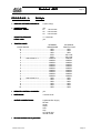
3. T E C H N I C A L D A T A ..................................................................................................... 29
3.1 Mechanical measurements ............................................................................................... 29
3.2 Power supply .................................................................................................................... 30
3.3 Conections and types of connections ............................................................................... 31
STARTCLOCK MANUAL COPYRIGHT BY:
Version E-93-12-09
ALGE-TIMING
AUSTRIA
Page 1
Star
tc
loc
k ASC1
Startc
tcloc
lock
Page 2
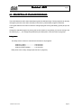
1. G E N E R A L
1.1 WHY AN ALGE STARTCLOCK ASC1:
TIMING DEVICE:
The ALGE Startclock, a microprocessor controlled timing device with analog and digital displays,
incorporates itself in the “ALGE-TIMING” family well. Timing accuracy is to the 1/1000 of a second.
SYNCHRONIZEABLE:
You can synchronize the ALGE Startclock with other timers. Through pushing a start button or with a
external start impulse it is possible to synchronize the Startclock with other timers.
COUNT DOWN:
In regular intervals or by pushing a start button an acoustic count down starts. It is possible to plug an
external speaker.
TRAFFIC LIGHT CONTROL:
With the acoustic count down a semaphore shows the count down condition in the right upper corner
of the Startclock. It is also possible to plug an external traffic light (with red, yellow, and green).
START IMPULSE OUTPUT:
Together with the acoustic start signal there is a start impulse (e.g. for start gates or start impulse for
primary timing).
REMOTE CONTROL:
With optional equipment ASC-TELE remote control it is possible to turn the count down off, or switch
between the three count down times. When using program 2, 3, or 5, do not plug the remote control. If
you plug it, it makes you all the time intermediate impulses.
TIME MEASUREMENT:
Max. three timing channels for start gates, photocells or hand switches. Precision to 1/1000 seconds
(e.g. for start time intermediate time or final time).
LEAD - LAG TIMING:
The lead or lag time is automatically measured and showed on the display.
Version E-93-12-09
Page 2
Star
tc
loc
k ASC1
Startc
tcloc
lock
Page 3
BACK-UP TIMING:
Together with the function as a Startclock it is very useful for back-up timing.
DATA STORAGE:
All timing impulse will be stored in the ASC1 memory. They stay in the memory until they are cleared.
OUTPUT OF ALL TIMING IMPULSES:
All timing impulses, as well as the lead or lag times will be printed with channel- and memory number.
All the stored times can be printed or shown at the display at a later time, even after turning the ASC1
off.
THE ALGE ASC1 IS EASY TO
HANDLE:
There is for almost all races a program stored in the ASC1, which you can select with the input of the
program number.
I T IS U N I V E R S L E Q U I P M E N T :
The data of the stored programs are easy to change for a special race.
COMPUTER INTERFACE:
The ASC1 can be plugged to a computer through a RS 232C compatible interface.
BATTERY CONTROL:
A meter on upper left corner of the front side shows the condition of the battery. If the meter is in the read
area the battery has to be recharged.
If the supply continues to get lower the ASC1 turns off in two steps:
- Step 1:
Second hand and printing stops. Minute hand and count down continue until voltage goes down
to step 2. The times will be still measured, stored and shown on the display. As soon as the
supply is o.k. again the ASC1 works compleate again.
- Step 2:
ASC1 switches complete off, but stores the memory.
ELECTRICAL SUPPLY:
External supplied with 12 to 15 VDC or with built in rechargeable batteries and recharger (110 VAC or
220-240 VAC)
Version E-93-12-09
Page 3
Star
tc
loc
k ASC1
Startc
tcloc
lock
Page 4
1.2. B A S I C E Q U I P M E N T :
The ALGE Startclock ASC1 comes standard without the “power-pack” (battery cell with charger).
With an external supply of 12 to 15 VDC is the ASC1 completely functional and does not need further
optional equipment.
If the ASC1 is used as a Startclock and back-up timer the parallel contacts or start and finish contacts
have to be connected.
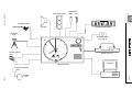
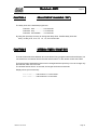
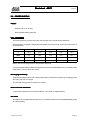
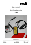
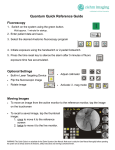
1.3. O P T I O N A L E Q U I P M E N T :
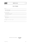
The ALGE ASC1 completes the big ALGE-TIMING family. Every ALGE device (e.g. photocell, printer,
startgate, etc.) can be plugged into the ASC1.
ALGE devices which can be used with the Startclock ASC1:
-
up to three photocells
-
startgate
-
hand switch
-
printer
-
external speaker
-
headphones with speech amplifier SV3
-
remote control ASC-TELE
-
external traffic light
-
computer through RS 232 C interface
-
tripod to set up the Startclock
Version E-93-12-09
Page 4
Handswitch
Version E-93-12-09
Start Trafic Light
Start
Stop
Startgate STSc
Speaker
Display Board GAZc
Photocell
RLSc
Startmicrphone
SM7
Printer P3 or P4
Startclock ASC1
Star
tc
loc
k ASC1
Startc
tcloc
lock
Remote Control
ASC-TELE
Computer
Speech-amplifier
SV3
Page 5
Page 5
Headset
Q34
Star
tc
loc
k ASC1
Startc
tcloc
lock
Page 6
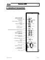
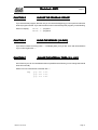
2. H O W T O U S E T H E S T A R T C L O C K
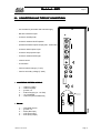
2.1. OPERATING ELEMENTS:
1. ANALOG CLOCK:
Clock is microprocessor controlled and shows the time of day.
2. DISPLAY:
Seven segment display with eight digits. Display according to the function switch, e.g. time of
day, finish time, running time, lead or lag, count down time, ...
3. INPUT KEYS:
This keys are used to control the ASC1 (e.g. input of time of day, interval times, program
number,...)
+ .. plus:
count up
- ... minus: count down
* .. star:
confirm key and move cursor to the right Push “*” and “-” together to move the
cursor to the left.
4. FUNCTION SWITCH:
Switch with 16 different positions. Position of the switch controls the interface (e.g. time of
day, start time, finish time,...).
5. INTERNAL SEMAPHORE
SEMAPHORE:
Internal semaphore displays red or green depending on the countdown.
6. INTERNAL SPEAKER:
Acoustic 4 ohm speaker inside the ASC1.
7. VOLTAGE CONTROL:
Meter in the upper left corner of the front side of the Startclock shows the battery condition.
Battery is o.k. as long the hand is not in the red.
Version E-93-12-09
Page 6
Star
tc
loc
k ASC1
Startc
tcloc
lock
Page 7
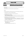
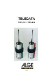
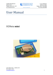
2.2. DESCRIPTION OF THE CONNECTIONS:
Remote control Tele
Startmicrophone SM7
Photocell RLSc
Handswitch
External supply (11 to 15 Volt)
Computer
Display board GAZc
Comet
Printer P3 or P4
Photocell
Ext. Supply
RS 232
Printer
External speaker
Start impulse output (potential free contact)
Output
Startgate STSc
Photocell adapter LA4
Speech amplifier SV3
Handswitch
Start
Stop
Photocell adapter LA4
Handswitch
Ext. Signal Light
External start traffic light
Volume
for countdown speaker
On/Off switch
Fuse T 1,5 A
Charging control lamp
On / Off
F1 T1,5A
Charge
F2 T1,0A
Charging outlet
to charge the battery
Fuse T 1,0 A
Version E-93-12-09
Page 7
Star
tc
loc
k ASC1
Startc
tcloc
lock
Page 8
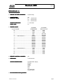
2.3. DESCRIPTION OF STANDARD PROGRAMS:
The ALGE Startclock ASC1 has 8 standard programs for different usage. These programs can be easy
changed by the user of the ASC1 and stay in the memory until another program is selected.
Turning the Startclock off does not clear the changed program as long the battery (power pack) is not
empty.
Change the standard program by turning the function switch to the position you want to change. Use
the input keys (+,-,*) to change the parameters (see description of function kees on page 20).
Delay times:
The delay times for the time channels are the same in all programs:
Channel 1 (start) ....................... 0.50 seconds
Channel 2 (stop) ....................... 0.12 seconds
Channel 3 (intermediate) .......... 0.12 seconds
Delay times can be easy changed (see function A, page 25).
Version E-93-12-09
Page 8
Star
tc
loc
k ASC1
Startc
tcloc
lock
Page 9
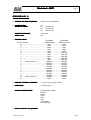
PROGRAM 0:
-
AMOUNT OF TIME CHANNELS:
2 (Start, Stop)
-
COUNT-DOWN:
INTERVAL TIMES:
yes
C1
C2
C3
-
START TOLERANCE:
LEAD / LAG:
+/- 5 seconds
no
-
TRAFFIC LIGHT:
1.00 minutes
0.30 minutes
0.40 minutes
INTERNAL
SEMAPHORE
COUNT-DOWN
EXTERNAL
TRAFFIC LIGHT
10 ............................................................ RED .......................... RED
9 ............................................................ RED .......................... RED
8 ............................................................ RED .......................... RED
7 ............................................................ RED ...................... YELLOW
6 ............................................................ RED ...................... YELLOW
5 .........Start tolerance 1 ...................... GREEN ..................... GREEN
4 .......................................................... GREEN ..................... GREEN
3 .......................................................... GREEN ..................... GREEN
2 .......................................................... GREEN ..................... GREEN
1 .......................................................... GREEN ..................... GREEN
0 .......................................................... GREEN ..................... GREEN
-1 .......................................................... GREEN ..................... GREEN
-2 .......................................................... GREEN ..................... GREEN
-3 .......................................................... GREEN ..................... GREEN
-4 .......................................................... GREEN ..................... GREEN
-5 .........Start tolerance 2 ........................ RED .......................... RED
-6 ............................................................ RED .......................... RED
-7 ............................................................ RED .......................... RED
-8 ............................................................ RED .......................... RED
-9 ............................................................ RED .......................... RED
-10 ............................................................ RED .......................... RED
-
REMOTE CONTROL CHANNEL:
yes
-
PRECISION:
1/100 secunds
-
ACTIVE CONNECTIONS:
Lightbeam/Ext. Supply
RS 232
printer
output
start
stop
ext. signal light
remote control
-
No intermediate time is possible!
Version E-93-12-09
Page 9
Star
tc
loc
k ASC1
Startc
tcloc
lock
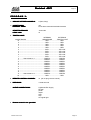
PROGRAM 1:
Page 10
Ski Alpin
-
AMOUNT OF TIME CHANNELS:
2 (Start, Stop)
-
COUNT-DOWN:
INTERVAL TIMES:
yes
C1
C2
C3
-
START TOLERANCE:
LEAD / LAG:
+/- 5 seconds
yes
-
TRAFFIC LIGHT:
1.00 minutes
0.30 minutes
0.40 minutes
INTERNAL
SEMAPHORE
COUNT-DOWN
EXTERNAL
TRAFFIC LIGHT
10 ............................................................ RED .......................... RED
9 ............................................................ RED .......................... RED
8 ............................................................ RED .......................... RED
7 ............................................................ RED ...................... YELLOW
6 ............................................................ RED ...................... YELLOW
5 ......... Start tolerance 1 ...................... GREEN ..................... GREEN
4 .......................................................... GREEN ..................... GREEN
3 .......................................................... GREEN ..................... GREEN
2 .......................................................... GREEN ..................... GREEN
1 .......................................................... GREEN ..................... GREEN
0 .......................................................... GREEN ..................... GREEN
-1 .......................................................... GREEN ..................... GREEN
-2 .......................................................... GREEN ..................... GREEN
-3 .......................................................... GREEN ..................... GREEN
-4 .......................................................... GREEN ..................... GREEN
-5 ......... Start tolerance 2 ........................ RED .......................... RED
-6 ............................................................ RED .......................... RED
-7 ............................................................ RED .......................... RED
-8 ............................................................ RED .......................... RED
-9 ............................................................ RED .......................... RED
-10 ............................................................ RED .......................... RED
-
REMOTE CONTROL CHANNEL:
yes
-
PRECISION:
1/100 secunds
-
ACTIVE CONNECTIONS:
Lightbeam/Ext. Supply
RS 232
printer
output
start
stop
ext. signal light
remote control
-
No intermediate time is possible!
Version E-93-12-09
Page 10
Star
tc
loc
k ASC1
Startc
tcloc
lock
Page 11
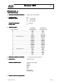
PROGRAM 2:
-
AMOUNT OF TIME CHANNELS:
3 (Start, Stop, Intermediate)
-
COUNT-DOWN:
INTERVAL TIMES:
yes
C1
C2
C3
-
START TOLERANCE:
LEAD / LAG:
-9 seconds
yes
-
TRAFFIC LIGHT:
COUNT-DOWN
1.30 minutes
1.00 minutes
0.40 minutes
INTERNAL
SEMAPHORE
EXTERNAL
TRAFFIC LIGHT
10 ............................................................ RED .......................... RED
9 ............................................................ RED .......................... RED
8 ............................................................ RED .......................... RED
7 ............................................................ RED .......................... RED
6 ............................................................ RED .......................... RED
5 ............................................................ RED ...................... YELLOW
4 ............................................................ RED ...................... YELLOW
3 ............................................................ RED ...................... YELLOW
2 ............................................................ RED ...................... YELLOW
1 ............................................................ RED ...................... YELLOW
0 .........Start tolerance 1 ...................... GREEN ..................... GREEN
-1 .......................................................... GREEN ..................... GREEN
-2 .......................................................... GREEN ..................... GREEN
-3 .......................................................... GREEN ..................... GREEN
-4 .......................................................... GREEN ..................... GREEN
-5 .......................................................... GREEN ..................... GREEN
-6 .......................................................... GREEN ..................... GREEN
-7 .......................................................... GREEN ..................... GREEN
-8 .......................................................... GREEN ..................... GREEN
-9 .........Start tolerance 2 ...................... GREEN ..................... GREEN
-10 ............................................................ RED .......................... RED
-
REMOTE CONTROL CHANNEL:
no (do not plug remote control!)
-
PRECISION:
1/1000 secunds
-
ACTIVE CONNECTIONS:
Lightbeam/Ext. Supply
RS 232
printer
output
start
stop
intermediate
ext. signal light
-
Remote control is not possible!
Version E-93-12-09
Page 11
Star
tc
loc
k ASC1
Startc
tcloc
lock
Page 12
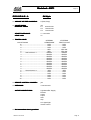
PROGRAM 3:
-
AMOUNT OF TIME CHANNELS:
2 (Start, Stop)
-
COUNT-DOWN:
INTERVAL TIMES:
yes
Count down start with handswitch 022-02
-
START TOLERANCE:
LEAD / LAG:
-9 seconds
no
-
TRAFFIC LIGHT:
COUNT-DOWN
INTERNAL
SEMAPHORE
EXTERNAL
TRAFFIC LIGHT
10 ............................................................ RED .......................... RED
9 ............................................................ RED .......................... RED
8 ............................................................ RED .......................... RED
7 ............................................................ RED .......................... RED
6 ............................................................ RED .......................... RED
5 ............................................................ RED ...................... YELLOW
4 ............................................................ RED ...................... YELLOW
3 ............................................................ RED ...................... YELLOW
2 ............................................................ RED ...................... YELLOW
1 ............................................................ RED ...................... YELLOW
0 ......... Start tolerance 1 ...................... GREEN ..................... GREEN
-1 .......................................................... GREEN ..................... GREEN
-2 .......................................................... GREEN ..................... GREEN
-3 .......................................................... GREEN ..................... GREEN
-4 .......................................................... GREEN ..................... GREEN
-5 .......................................................... GREEN ..................... GREEN
-6 .......................................................... GREEN ..................... GREEN
-7 .......................................................... GREEN ..................... GREEN
-8 .......................................................... GREEN ..................... GREEN
-9 ......... Start tolerance 2 ...................... GREEN ..................... GREEN
-10 ............................................................ RED .......................... RED
-
REMOTE CONTROL CHANNEL:
no (do not plug remote control!)
-
PRECISION:
1/1000 secunds
-
ACTIVE CONNECTIONS:
Lightbeam/Ext. Supply
RS 232
printer
output
start
stop
ext. signal light
-
Remote control is not possible!
Version E-93-12-09
Page 12
Star
tc
loc
k ASC1
Startc
tcloc
lock
Page 13
PROGRAM 4:
-
AMOUNT OF TIME CHANNELS:
2 (Start, Stop)
-
COUNT-DOWN:
INTERVAL TIMES:
yes
C1
C2
C3
-
START TOLERANCE:
LEAD / LAG:
+/- 3 seconds
yes
-
TRAFFIC LIGHT:
0.30 minutes
0.20 minutes
1.00 minutes
INTERNAL
SEMAPHORE
COUNT-DOWN
EXTERNAL
TRAFFIC LIGHT
10 ............................................................ RED .......................... RED
9 ............................................................ RED .......................... RED
8 ............................................................ RED .......................... RED
7 ............................................................ RED ...................... YELLOW
6 ............................................................ RED ...................... YELLOW
5 .........Start tolerance 1 ...................... GREEN ..................... GREEN
4 .......................................................... GREEN ..................... GREEN
3 .......................................................... GREEN ..................... GREEN
2 .......................................................... GREEN ..................... GREEN
1 .......................................................... GREEN ..................... GREEN
0 .......................................................... GREEN ..................... GREEN
-1 .......................................................... GREEN ..................... GREEN
-2 .......................................................... GREEN ..................... GREEN
-3 .......................................................... GREEN ..................... GREEN
-4 .......................................................... GREEN ..................... GREEN
-5 .........Start tolerance 2 ........................ RED .......................... RED
-6 ............................................................ RED .......................... RED
-7 ............................................................ RED .......................... RED
-8 ............................................................ RED .......................... RED
-9 ............................................................ RED .......................... RED
-10 ............................................................ RED .......................... RED
-
REMOTE CONTROL CHANNEL:
yes
-
PRECISION:
1/100 secunds
-
ACTIVE CONNECTIONS:
Lightbeam/Ext. Supply
RS 232
printer
output
start
stop
intermediate
ext. signal light
remote control
-
No intermediate time is possible!
Version E-93-12-09
Page 13
Star
tc
loc
k ASC1
Startc
tcloc
lock
Page 14
P R O G R A M 4:
-
AMOUNT OF TIME CHANNELS:
3 (Start, Stop, Intermediate)
-
COUNT-DOWN:
INTERVAL TIMES:
yes
C1
C2
C3
-
START TOLERANCE:
LEAD / LAG:
+/- 3 seconds
no
-
TRAFFIC LIGHT:
COUNT-DOWN
1.00 minutes
0.30 minutes
0.40 minutes
INTERNAL
SEMAPHORE
EXTERNAL
TRAFFIC LIGHT
10 ............................................................ RED .......................... RED
9 ............................................................ RED .......................... RED
8 ............................................................ RED .......................... RED
7 ............................................................ RED ...................... YELLOW
6 ............................................................ RED ...................... YELLOW
5 ......... Start tolerance 1 ...................... GREEN ..................... GREEN
4 .......................................................... GREEN ..................... GREEN
3 .......................................................... GREEN ..................... GREEN
2 .......................................................... GREEN ..................... GREEN
1 .......................................................... GREEN ..................... GREEN
0 .......................................................... GREEN ..................... GREEN
-1 .......................................................... GREEN ..................... GREEN
-2 .......................................................... GREEN ..................... GREEN
-3 .......................................................... GREEN ..................... GREEN
-4 .......................................................... GREEN ..................... GREEN
-5 ......... Start tolerance 2 ........................ RED .......................... RED
-6 ............................................................ RED .......................... RED
-7 ............................................................ RED .......................... RED
-8 ............................................................ RED .......................... RED
-9 ............................................................ RED .......................... RED
-10 ............................................................ RED .......................... RED
-
REMOTE CONTROL CHANNEL:
no (Do not plug remote control!)
-
PRECISION:
1/1000 secunds
-
ACTIVE CONNECTIONS:
Lightbeam/Ext. Supply
RS 232
printer
output
start
stop
intermediate
ext. signal light
-
Remote control is not possible!
Version E-93-12-09
Page 14
Star
tc
loc
k ASC1
Startc
tcloc
lock
PROGRAM 6:
Page 15
Ski Alpin
-
AMOUNT OF TIME CHANNELS:
2 (Start, Stop)
-
COUNT-DOWN:
INTERVAL TIMES:
yes
C1
C2
C3
-
START TOLERANCE:
LEAD / LAG:
+/- 5 seconds
no
-
TRAFFIC LIGHT:
0.40 minutes
1.00 minutes
1.30 minutes
INTERNAL
SEMAPHORE
COUNT-DOWN
EXTERNAL
TRAFFIC LIGHT
10 ............................................................ RED .......................... RED
9 ............................................................ RED .......................... RED
8 ............................................................ RED .......................... RED
7 ............................................................ RED ...................... YELLOW
6 ............................................................ RED ...................... YELLOW
5 .........Start tolerance 1 ...................... GREEN ..................... GREEN
4 .......................................................... GREEN ..................... GREEN
3 .......................................................... GREEN ..................... GREEN
2 .......................................................... GREEN ..................... GREEN
1 .......................................................... GREEN ..................... GREEN
0 .......................................................... GREEN ..................... GREEN
-1 .......................................................... GREEN ..................... GREEN
-2 .......................................................... GREEN ..................... GREEN
-3 .......................................................... GREEN ..................... GREEN
-4 .......................................................... GREEN ..................... GREEN
-5 .........Start tolerance 2 ........................ RED .......................... RED
-6 ............................................................ RED .......................... RED
-7 ............................................................ RED .......................... RED
-8 ............................................................ RED .......................... RED
-9 ............................................................ RED .......................... RED
-10 ............................................................ RED .......................... RED
-
REMOTE CONTROL CHANNEL:
yes
-
PRECISION:
1/100 secunds
-
ACTIVE CONNECTIONS:
Lightbeam/Ext. Supply
RS 232
printer
output
start
stop
ext. signal light
remote control
-
No intermediate time is possible!
Version E-93-12-09
Page 15
Star
tc
loc
k ASC1
Startc
tcloc
lock
PROGRAM 13:
Page 16
GUNDERSON METHOD
-
AMOUNT OF TIME CHANNELS:
no timing channels
-
COUNT DOWN AND
INTERVAL TIMES:
input from Comet (+/-Timer)
-
TRAFFIC LIGHT:
no
-
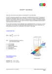
DISPLAY BOARD:
You can show on display boards the startnumber and
count-down time for the next ten starts. You can control
up to ten display boards with the Startclock.
position of
thumb wheel
switch
position
of shift
switch
description of switch
1
1
2
2
3
3
up
middle
up
middle
up
middle
startnumber of the next competitor
count down for the next competitor
startnumber of the 2nd competitor
time between start of 1st and 2nd competitor
startnumber of the 3rd competitor
time between start of 2nd and 3rd competitor
How to use the Startclock with the Comet and display board:
-
Input the start times in the Comet (program +/-Timer,”input start time”).
-
Turn the Startclock on and set the time.
-
Start the Startclock and turn on program 13.
-
Transmit the start times from the Comet to the Startclock (cable 064-01). When transmission
starts it shows on the display the transmitted startnumbers (use Comet program “transfer startt.”).
-
Plug the display board with the Startclock (cable 060-10).
Version E-93-12-09
Page 16
Star
tc
loc
k ASC1
Startc
tcloc
lock
Page 17
2.4. S E T T H E A L G E S T A R T C L O C K A S C 1 :
After switching the Startclock on you have to set the clock and input the program number. The following
shows exactly how to run the Startclock.
EXAMPLE:
It is now 2:23 pm. The Startclock is turned off and shows as analog time 5:24:20. You choose the alpine
program 1.
-
Turn the Startclock on.
** The display shows “SUSANNE”, “ALGE”, “UHR STEL”; the second and minute hand is moved
two times. “UHR STEL” means set the clock.
-
Press the key “*”. The display shows the last stored time.
** The display shows “17:34:00”. The first digit blinks.
-
Use the input keys for the input of the time (14:25:00). “+” key: to count the blinking digit up
“-” key:
to count the blinking digit down
“*” key:
to move one digit to the left
“*” and “-” key together: to move one digit to the left
-
Since “1” is o.k. just press (*).
** The display shows “17:34:00” and the “7” blinks.
-
Press three times “-”, then “*”, “-”, “*” and “+”.
** The display shows the following in a row:
16:34:00
15:34:00
14:34:00
14:34:00
14:24:00
14:24:00
14:25:00
-
the second digit blinks
the third digit blinks
the fourth digit blinks
Press now “*”
** The display shows now “17:34:00 A”
“A” stays for analog and means you have to input the time the analog clock shows right now.
For this example it would be “17:36:02” (the second and minute hand moved two positions).
-
Input the analog time “17:36:22” (do it the same way as the time “14:25:00”) and press “*” after
the last adjustment.
** The display continues to show the analog time, while first the second hand, then the minute and
hour hand moves to 2:25:00 pm. Afterwards the display and the analog clock shows the time of
day (display blinks).
-
Confirm with “*” if time of day is correct, otherwise press “-”. If you press “-” you have to input again
the synchronize time and the time the analog clock shows. If you confirmed with “*” the display
shows:
Version E-93-12-09
Page 17
Star
tc
loc
k ASC1
Startc
tcloc
lock
Page 18
** “SYNC A”, the Startclock is now ready to synchronize together with other timing equipment.
-
The Startclock can be synchronized in two ways:
- pressing the “*” key
- giving a startimpulse
As soon as you press the “*” or give a start impulse the clock starts to run.
** The display shows “CLEAR”.
-
All start and stop impulses are stored in a memory.
- for a new race press “*” to clear the memory
- to keep the memory stored press “+” or “-”
The memory can store a maximum of 1500 times.
** The display shows:
for (*)
“SURE”
for (+) or (-)
“SPEICH” (stored)
-
If the display shows “SURE” and you want to clear the memory press “*”.
** “CLEARED” on the display shows that the memory is cleared.
** The display shows “PROGR 0”. The program number is blinking. It shows always the program
number you used the last time (in this example 0).
-
With the input keys “+,-,*” you choose the program number you want. “+” .... count program
number up
- ........ count program number down
* ....... confirm program shown on display
For program 1 press “+” and confirm with “*”.
** The Startclock is now ready and starts with the first count down 10 seconds before the next
minute starts.
What the display shows depends on the position of the function switch.
e.g. function switch on 0 .... display shows running time
function switch on F .... display shows interval time
Version E-93-12-09
Page 18
Star
tc
loc
k ASC1
Startc
tcloc
lock
Page 19
2.5. DESCRIPTION OF THE FUNCTION SWITCH:
This switch has 16 positions. The position of the switch controls the display.
For each input or output of the Startclock you have to set first the function switch in the right position.
Function 5 to F shows fist a program text on the display. If you press key “*” it starts the mode.
On the following pages will describe all positions of the function switch.
Version E-93-12-09
Page 19
Star
tc
loc
k ASC1
Startc
tcloc
lock
FUNCTION 0
Page 20
DISPLAY SHOWS TIME OF DAY
With the “*” key you can switch between two modes
-
Shows the time of day on the display. After every start it shows the lead or lag time for 10
seconds.
LEAD TIME ..... time from competitor start until start sound
LAG TIME ....... time from the start sound until competitor starts
-
Switching on or off the “Code Lock”:
The Startclock can be protected by a code. Nobody can change than the programs without
the code (code is “2002”)
turn the function switch on position 0
o
o
o
o
press key “*”
display shows “code 0000”
if you input code with “2002” the code protection is turned on
to turn the code protection off repeat the same process
With the code protection turned on, you have to input the code before every change of
programs.
EXAMPLE: The code protection is switched on, the interval time 1 should be switched from
1:00 to 0:30 minutes.
1.
2.
3.
4.
5.
6.
Function switch on position “B”. Display shows “COUNT-DO”
Press key “*”, display shows “CODE 0000”.
Input code “2002” with input key.
Confirm with “*”.
Change interval time to 0:30 minutes.
To make the code again active switch the function switch to another position.
FUNCTION 1
DISPLAY SHOWS START TIMES
Choose between two modes by pressing the key “*”.
-
Display shows the start time of the last competitor.
Display shows e.g. “14:30:00.12”
If there has not been a start impulse yet, the display shows blinking the time of day.
-
Recall start times:
If you press key “*” the display shows “DISPLAY”. If you press now “-” the display shows the
first stored time in the memory.
If you press first “*” and the “+” the display shows first the last stored time. By pressing either “+” or
“-” the display shows either the next higher or lower start time. If you press “*” the display shows the
last start impulse again.
Version E-93-12-09
Page 20
Star
tc
loc
k ASC1
Startc
tcloc
lock
FUNCTION 2
Page 21
DISPLAY SHOWS FINISH TIMES
Choose between two modes by pressing the key “*”.
-
Shows the last finish time
The display shows e.g. “15:39:25.17”
If there has not been a finish impulse yet, the display shows blinking the time of day.
-
Recall finish times:
All finish times are stored and can be shown at the display
any time.
If you press “*” key the display shows “DISPLAY”. If you press now “-” the display shows the first
stored time in the memory.
If you press first “*” and the “+” the display shows first the latest stored time. By pressing either “+”
or “-” the display shows either the next higher or lower finish time.
If you press “*” again the display shows again the last finish time.
FUNCTION 3
DISPLAY SHOWS INTERMEDIATE TIMES
With the key “*” you can switch between two modes.
-
Display shows the last intermediate time
e.g. Display shows “15:56:23.67”
If there has not been a intermediate impulse yet, display shows blinking the time of day.
-
Recall intermediate times
All intermediate times are stored and can be shown any time at the display.
If you press the “*” key the display shows “DISPLAY”. If you press now “-”, the display shows the
first stored time in the memory.
If you press first “*” and then “+” the display shows first the last stored time. By pressing either “+”
or “-” the display shows either the next higher or lower intermediate time.
If you press “*” again the display shows the last intermediate time.
FUNCTION 4
LEAD / LAG TIME
With the key “*” you can switch between two modes.
-
Display shows the last lead or lag time
e.g. Display shows “-0:00.17”
If there has not been a start impulse yet, display shows blinking the time of day.
-
Recall lead or lag times
All intermediate times are stored and can be shown any time at the display.
If you press the “*” key the display shows “DISPLAY”. If you press now “-”, the display shows the
first stored lead or lag time in the memory.
If you press first “*” and then “+” the display shows first the last stored time. By pressing either “+”
or “-” the display shows either the next higher or lower lead or lag time.
If you press “*” again the display shows the last lead or lag time.
Version E-93-12-09
Page 21
Star
tc
loc
k ASC1
Startc
tcloc
lock
FUNCTION 5
Page 22
BREAK SWITCH (“CD RUN” or “CD STOP”)
In case of a race break you can stop the count down in this position.
If you press the “-” key the count down stops until you press the “+” key.
The display shows either “CD STOP” or “CD RUN”.
After a count down stop and run, the first count down starts 10 seconds before the next exact minute.
FUNCTION 6
TEST PROGRAM (“TEST-PRO”)
If you installed all required appliances with the start clock and the start clock is not working in the way
it is supposed to work you can check for some functions whith this program.
All checks show first a text. With “*” you go to the next test, with “+” you go back to the check before.
-
“FUNC 6”
Show the position of the function switch. With pressing the “*” key the test program starts.
-
“TASTER”
Shows the input key you press.
“P” for “+”, “-” for “-” and “E” for “*”.
If you press “*” two times you get the next check point.
-
“DISPLAY”
The display counts all digits from 0 to 9.
-
Battery condition “BATT HIGH” or “BATT OUT”:
Shows “BATT HIGH” for charged battery, and “BATT LOW” for a empty battery.
-
Speaker test “LS TEST”:
There is an alternating high and low beep from the speaker.
-
Traffic light “SIGNAL: G”:
The semaphore shows alternating red or green and the display shows “r” for red and “G” for green.
-
”PRINT”
Printer prints all printing signs.
Version E-93-12-09
Page 22
Star
tc
loc
k ASC1
Startc
tcloc
lock
FUNCTION 7
Page 23
PRINTER (“PR-AUSDR”)
All times are stored and can be printed any time.
Is function switch on position 7 the display shows the channels it prints continuously.
e.g.: “C:1-2” .... it prints all times from channel 1 and 2
“C:1A23” ... it prints all three channels and lead or lag times
CHANNEL 1 ................... Start channel
CHANNEL A .................. Lead-, lag-time
CHANNEL 2 ................... Stop channel
CHANNEL 3 ................... Intermediate channel
The blinking channel can be switched on with “+”, or switched off with “-”. To the next digit to the right
you get by pressing the “*” key, to the digit to the left by pressing “-” and “*” together.
After you set the channels, which you want to print, you have to input the time of the first output of
the stored times. The display shows “00:00”. Are you interested only in the stored times after 10:25,
input “10:25”. All times after 10:25 of the channels you have chosen will be printed.
You can stop the printing by switching the function switch to an other position.
If you set the time 00:00, it will print form now on only the channels you just input. After input of a
standard program all channels of the program are printed.
Version E-93-12-09
Page 23
Star
tc
loc
k ASC1
Startc
tcloc
lock
FUNCTION 8
Page 24
INTERFACE (“INTERFAC”)
The Startclock ASC1 has a RS 232 C compatible interface to plug in a computer, printer, display
board, etc. In function 8 you can set the interface parameters.
Standard parameters:
2400 baud, DC1/DC3 handshake, 8 data bits, no parity bit
The parameters can be changed easy with the input keys:
-
BAUDRATE:
300, 600, 1200, 2400, 4800
-
HANDSHAKING:
DC1/DC3 or DTR hardware handshaking
-
8 DATA BIT:
no changes are possible
-
NO PARITY:
no changes are possible
FUNCTION 9
TRAFFIC LIGHT (“CD: 10 :RT”)
With this function you can program the traffic light. The count down start by 10 and goes down to 0
and from -1 to -10. The start beep is with 0 seconds.
With the input key “+” you can choose the colour.
red ............................. “RT”
yellow ........................ “YE”
green ......................... “GR”
traffic light off ............. “ “
With the input key “*” you count down.
Attention: You must input the complete count down form 10 to zero to -10. You are not allowed to leave Function 9 before reaching -10.
e.g.: the display shows:
“CD: 5: RT”
the traffic light shows 5 seconds before the start red.
press key “*”
“CD: 4: RT”
press key “+”
“CD: 4: YE”
Version E-93-12-09
the traffic light should show yellow four seconds before the start
Page 24
Star
tc
loc
k ASC1
Startc
tcloc
lock
FUNCTION A
Page 25
DELAY TIME OF CHANNELS “TOT”)
The delay times in the standard program are:
Channel 1 start ................... 0.50 seconds
Channel 2 stop ................... 0.12 seconds
Channel 3 intermediate ...... 0.12 seconds
By using the input keys it is easy to change the delay times. Possible delay times are:
0.00 (= 0.002), 0.03, 0.12, 0.5, 1.0, 1.5, and 2.0 seconds.
FUNCTION B
INTERVAL TIMES (“COUNT-DO”)
The interval time is the time between two count downs. Every program has three interval times. You
can switch from one interval time to the other with function F or the remote control ASC-TELE.
The interval time of standard programs can be changed with the input keys. You can change only
the intervals, which are not in use.
The shortest interval time is 12 seconds, the longest 9 minutes 59 seconds.
Display shows (C3 is turned on):
“C1: 1:30” ........ interval time 1 is 1:30 minutes
“C2: 0:15” ........ interval time 2 is 15 seconds
Version E-93-12-09
Page 25
Star
tc
loc
k ASC1
Startc
tcloc
lock
FUNCTION C
Page 26
RESET START CLOCK TIME (“UHR STELLEN”)
With this function you stop the start clock and you are able to set it new and make a new
synchronization.
To set the Startclock you do the same as after turning the Startclock on.
Example:
The Startclock stopped at 14:22 and 34 seconds. The new synchronization should be at 14:25.
o The display shows 14:22:00. The first digit is blinking.
-
Set the display with the input keys to 14:25:00 and confirm with “*”.
o The display shows now “14:22:00 A”.
“A” stays for analog and means, input the time the analog clock shows right now. In this example
14:22:34. Use the input keys to input it.
o The display shows 14:22:34 A and the second, the minute, and hour hand are moving to the 14:25.
Now the display shows the 14:25 too, but it blinks.
-
If the clock shows the time you want you can confirm with “*”, otherwise press “-”. If you pressed
“-” you have to input again the synchronize time and the time the analog clock shows right now.
If you pressed “*” the display shows:
o ”SINC A”, the start clock is ready for synchronization.
-
The clock can be synchronized in two ways:
Press “*” again
Through a start impulse
The synchronizing impulse should be at exactly 14:25.
Version E-93-12-09
Page 26
Star
tc
loc
k ASC1
Startc
tcloc
lock
FUNCTION D
Page 27
CHOOSE THE PROGRAM “PROGR”
If you want another program, than the one you choose at the beginning you can input in this function
another program number. If you switch to this function it shows always the program you use blinking.
Shows on display:
FUNCTION E
“PROGR: 1” ... program 1
“PROGR: 5” ... program 5
CLEAR THE MEMORY (“CLEAR”)
If you want to clear the memory press “*”. The display asks you if you are “sure” and clears all times
if you confirm again with “*”.
FUNCTION F
CHANGE THE INTERVAL TIMES (“C1: 1:30”)
In this function you can choose between the two possible interval times (you can change the interval
times in function B).
Switch from one interval time to another with “*”.
e.g.
Version E-93-12-09
(*) .... “C1: 1:30”
(*) .... “C2: 1:00”
(*) .... “C3: 0:40”
Page 27
Star
tc
loc
k ASC1
Startc
tcloc
lock
3.5.
Page 28
DESCRIPTION OF THE INTERFACE:
The Startclock has a RS 232 C compatible interface. The interface parameters are easy to choose (see
point 2.5 Function 8 on page 24)
The baud rate is working in normal steps of 300 to 4800. The Startclock can do DC1/DC3 as well as
hardware handshakes.
There is an output of all measured and calculated times with a precision of 1/1000.
You can plug at the interface:
-
Computer
Printer
Modem
Display boards
Acoustic coupler
Control codes:
-
‘??’ CR receives the Startclock two question marks and a CR, all stored times will be sent again.
-
‘CL’ CR receives the Startclock CL and CR the memory will be cleared.
-
‘FULL’ CR the Startclock sends ‘FULL’ and CR as soon as the memory is full.
Format or Timing output:
C1 HHMMSSzht
-MSSzht
C2 HHMMSSzht
C3 HHMMSSzht
ABCD LF CR .............. start time
LF CR ......................... lead or lag time
ABCD LF CR .............. stop time
ABCD LF CR .............. time channel 3 (intermediate)
C1 ......... channel number
HH ........ hours
MM ....... minutes
SS ......... seconds
z ............ tenth seconds
h ........... hundredth seconds
t ............ thousandth seconds
ABCD .... memory number of time
Version E-93-12-09
Page 28
Star
tc
loc
k ASC1
Startc
tcloc
lock
Page 29
3. T E C H N I C A L D A T A
Timing range:
23 hours, 59 minutes, 59,999 seconds
Accuracy:
+/- 0,0002 sec/h at 20°C (68 K)
+/- 0,009 sec/h at -15 to 50 °C (5 to 122 K)
Precision:
1/1000 seconds
Quartz frequency:
TCXO 11.52 MHz (temperature compensated crystal oscillator)
Operative temperature range:
-25 to 60°C (-13 to 140 F)
Memory:
max. 1500 times
All times are measured, calculated (lead, lag) and stored by 1/1000 of a second. The output in some of
the programs is only in 1/100, because of the rules in different sports.
3.1. MECHANICAL MEASUREMENTS:
The Startclock chassis is made of aluminium and can not rust at all.
For transportation the plexiglas is behind a cover and can not be scratched.
There are two straps on the back side to hang the start clock at the wall. A 3/8 inch tread at the bottom
makes it easy to fix the Startclock on a tripod.
Weight:
4.8 kg (15.56 lbs.)
Measurements:
450 x 330 x 110 mm (18.4 x 13.5 x 4.5 in.)
Hands:
seconds:
minutes:
hours:
Visibility:
about 35 meters (110 feet) for the second hand
about 50 meters (160 feet) for the minute hand and clock face
Version E-93-12-09
175 x 3 mm (7.2 x 0.12 in.) yellow
170 x 9 mm (7 x 0.4 in.)
white
110 x 12 mm (4.5 x 0.5 in.) white
Page 29
Star
tc
loc
k ASC1
Startc
tcloc
lock
Page 30
3.2. POWER SUPPLY:
Supply:
-
External with 12 to 16 VDC
-
Rechargeable battery (optional)
3.2.1. Powerpack:
The power pack is a gel cell (12V/1.8Ah) and charger which is built into the Startclock
With the battery completely charged and the speaker turned up to high volume the running time of
the Startclock is:
Prints
-20°C
-10°C
0°C
20°C
40°C
0
10 h
11 h
15 h
16 h
16 h
1000
9h
10 h
14 h
13 h
15 h
3000
8h
9h
12 h
13 h
13 h
6000
7h
8h
10 h
11 h
11 h
Battery life in hours, dependent on temperature and prints.
The rechargeable battery will last 5% longer if the printouts are made after the race. The battery lasts
longer also if you turn down the volume.
Recharging the battery:
The built in recharger makes over charging impossible. The Startclock needs only to be plugged into
220 VAC (110 VAC) to charge.
The average charging time is at least 6 to 9 hours.
How to store the Startclock:
To prevent the Startclock from having problems, store it with a charged battery.
AC outlet:
The Startclock is supplied either by 220 VAC or 110 VAC (see label), the rechargeable battery works
as a buffer battery.
Version E-93-12-09
Page 30
Star
tc
loc
k ASC1
Startc
tcloc
lock
Page 31
3.3. CONNECTIONS AND TYPES OF CONNECTIONS:
-
two sockets for photocells and external supply
-
RS 232c interface output
-
socket for ALGE printer
-
socket for external ALGE speaker
-
potential free start impulse output (max. 100V/0,5A)
-
socket for start impulse input
-
socket for stop impulse input
-
socket for external traffic light
-
volume control
-
on/off switch
-
fuse for internal charger (T 1,5A)
-
fuse for secondary voltage (T 0,8A)
- LIGHTBEAM / EXTERN SUPPLY:
1 ......
2 ......
3 ......
4 ......
5 ......
6 ......
channel 1 (start)
channel 2 (stop)
ground, 0 V
external supply (12 - 16 VDC)
+5 V regulated
channel 3 (intermediate time)
- RS 232:
1 ......
2 ......
3 ......
4 ......
5 ......
TXD (data output)
ground, 0 V
RXD (data input)
CTS (busy input)
RTS (busy output)
Version E-93-12-09
Page 31
Star
tc
loc
k ASC1
Startc
tcloc
lock
Page 32
- PRINTER:
1 ......
2 ......
3 ......
4 ......
5 ......
ground, 0 V
+12 Volts unregulated
data out
+12 Volts unregulated
data out
- LOUD SPEAKER:
o ...... ground (shuts off internal speaker)
o ...... signal
o ...... ground (operates both internal and external speaker)
- EXTERNAL SIGNAL LIGHT:
1 ......
2 ......
3 ......
4 ......
ground, 0 Volt
yellow
green
+12 Volts (operates both internal and external speaker)
Output code for external lamp driver:
Version E-93-12-09
yellow
green
lamp shows
off
off
red
on
off
yellow
off
on
green
on
on
off
Page 32
Star
tc
loc
k ASC1
Startc
tcloc
lock
Page 33
ALGE ST
AR
TCLOCK ASC 1 A
CCESSORIES
STAR
ARTCLOCK
ACCESSORIES
ALGE STARTCLOCK ASC1 .....................................................................................
.....
........
POWER-PACK WITH CABLE ..................................................................................
.....
........
TRIPOD ....................................................................................................................
.....
........
REMOTE CONTROL ASC-TELE .............................................................................
.....
........
REMOTE CONTROL CABLE (LENGTH) .................................................................
.....
........
PRINTER P3 ............................................................................................................
.....
........
EXTERNAL PRINTER CABLE (LENGTH) ...............................................................
.....
........
EXTERNAL LOUDSPEAKER (CABLE LENGTH) ....................................................
.....
........
TRAFFIC LIGHT (CABLE LENGTH) ........................................................................
.....
........
PHOTOCELL ............................................................................................................
.....
........
PHOTOCELL CABLE START (LENGTH) .................................................................
.....
........
PHOTOCELL CABLE STOP (LENGTH) ...................................................................
.....
........
STARTGATE (TYPE) ...............................................................................................
.....
........
STARTMICROPHONE SM6 .....................................................................................
.....
........
HANDSWITCH START (CABLE LENGTH) ..............................................................
.....
........
HANDSWITCH STOP (CABLE LENGTH) ................................................................
.....
........
HANDSWITCH OUNT-DOWN (COUNT DOWN) .....................................................
.....
........
HEADPHONE Q34 WITH SPEAKING AMPLIFIER ..................................................
.....
........
.................................................................................................................................
.....
........
.................................................................................................................................
.....
........
.................................................................................................................................
.....
........
.................................................................................................................................
.....
........
.................................................................................................................................
.....
........
.................................................................................................................................
.....
........
.................................................................................................................................
.....
........
Version E-93-12-09
Page 33