1
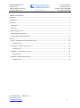
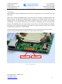
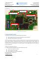
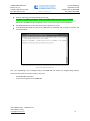
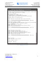
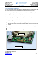
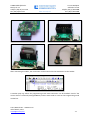
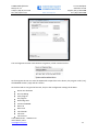
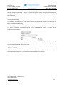
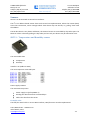
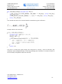
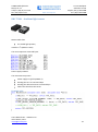
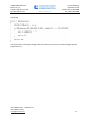
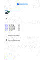
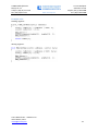
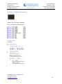
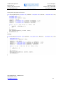
H-8000 Székesfehérvár
Berényi út 15.
Telefon: (36) 22/ 511-130
Fax: (36) 22/511-131
www.unicomp.hu
H-1117 Budapest
Fehérvári út 130.
Telefon: (36) 1/ 456-0998
Fax: (36) 1/456-0999
User Manual
UCMote mini
Users Manual v0.1 - UCMote mini
4th of March, 2011
[email protected]
1
H-8000 Székesfehérvár
Berényi út 15.
Telefon: (36) 22/ 511-130
Fax: (36) 22/511-131
www.unicomp.hu
H-1117 Budapest
Fehérvári út 130.
Telefon: (36) 1/ 456-0998
Fax: (36) 1/456-0999
Table of Content
Datasheet ................................................................................................................................................ 3
ATTENTION! ............................................................................................................................................. 4
First steps ................................................................................................................................................ 5
USB power ........................................................................................................................................... 6
Periferies ............................................................................................................................................. 7
Programming the mote. .......................................................................................................................... 7
USB programming (Linux).................................................................................................................... 7
JTAG programming (AVR Studio)....................................................................................................... 10
Sensors .................................................................................................................................................. 14
SHT21 – Temperature and Humidity sensor ..................................................................................... 14
Example code: ............................................................................................................................... 14
BH1750fvi – Ambient light sensor ..................................................................................................... 16
Example code: ............................................................................................................................... 16
BMA180 – 3D Acceleration sensor .................................................................................................... 18
Example code: ............................................................................................................................... 19
M25P16 – 16Mbit flash memory....................................................................................................... 20
Example code: ............................................................................................................................... 20
Users Manual v0.1 - UCMote mini
4th of March, 2011
[email protected]
2
H-8000 Székesfehérvár
Berényi út 15.
Telefon: (36) 22/ 511-130
Fax: (36) 22/511-131
www.unicomp.hu
H-1117 Budapest
Fehérvári út 130.
Telefon: (36) 1/ 456-0998
Fax: (36) 1/456-0999
Datasheet
MCU:
Antenna:
Flash:
Sensors:
Ambient light
Atmel ATmega128RFA1, 8-bit, radio 2,4GHz
Chip antenna
16Mbit, SPI
*Humidity, Temp
12bit/14bit, I2C
*3D accelerometer
*Barometric sensor
14bit, SPI
24bit, I2C
JTAG:
micro USB:
User interface:
for debugging and communication
for external power and communication
4 LEDs (+2 LEDs for external power presence and charging
indicator)
Both CR2450 non-rechargeable and LIR2450 rechargeable coin
battery
charging LIR2450 battery in case of present external power
TinyOS 2.x and NesC compatibility
Hammond 1551F, outside dimensions: 50mm X 35mm X 15mm
Battery:
Battery charger:
Software:
Enclosure:
16bit, I2C
Users Manual v0.1 - UCMote mini
4th of March, 2011
[email protected]
3
H-8000 Székesfehérvár
Berényi út 15.
Telefon: (36) 22/ 511-130
Fax: (36) 22/511-131
www.unicomp.hu
H-1117 Budapest
Fehérvári út 130.
Telefon: (36) 1/ 456-0998
Fax: (36) 1/456-0999
ATTENTION!
For the error free operation high temprature (above 85° Celsius) and the direct contact with water
should be avoided! The temperature affects the battery capacity.
Besides USB power, mini can be operated from both rechargeable (LIR2450) and non-rechargeable
(CR2450) coin battery. Since the voltage level of the two types of battery differs. (CR2450 ~3V,
LIR2450 ~4,2-3,6V) and in battery mode there is no regulator between the power source and the
MCU:
It is important to check the power source type switch, before inserting the power source
(accumulator or battery), since the incorrect selection can cause damage!
Battery (CR2450)
Rechargeable (LIR2450)
Picture 1: Battery type selection
Users Manual v0.1 - UCMote mini
4th of March, 2011
[email protected]
4
H-8000 Székesfehérvár
Berényi út 15.
Telefon: (36) 22/ 511-130
Fax: (36) 22/511-131
H-1117 Budapest
Fehérvári út 130.
Telefon: (36) 1/ 456-0998
Fax: (36) 1/456-0999
www.unicomp.hu
First steps
The battery should be inserted with the (+) side up. Incorrect polarity can damage the device.
Picture 2: Correct battery placement
The device can be turned ON or OFF by the switch circled on the photo below.
Switch ON
Switch OFF
Picture 3: Switching ON/OFF mini
Users Manual v0.1 - UCMote mini
4th of March, 2011
[email protected]
5
H-8000 Székesfehérvár
Berényi út 15.
Telefon: (36) 22/ 511-130
Fax: (36) 22/511-131
www.unicomp.hu
H-1117 Budapest
Fehérvári út 130.
Telefon: (36) 1/ 456-0998
Fax: (36) 1/456-0999
USB power
When USB power presents, mini automatically switches to USB power (it’s not necessary to turn the
device off)
When you are using rechargeable battery, the device starts to recharge it (charging indicator LED
lights up [Picture 5]). When the charging has been completed, the indicator blacks out. During the
charging process, the temperature of the battery should not go over 50° Celsius. If you observe
overheating, or any physical deformation on the battery, immediately pull out the USB cable,
because the exploding battery can cause serious injury or fire. If the output voltage of the battery
falls below 3.5V, it should be recharged, because the low voltage reduces the battery life. The fully
charged battery produces 4.2V output voltage.
In case you need reset condition, use the on/off switch, or use a conductive tool to make contact
between the ground GND) and reset (RST) pins on the JTAG connector surface.
RES pin
GND pin
Picture 4: Reseting mini
Users Manual v0.1 - UCMote mini
4th of March, 2011
[email protected]
6
H-8000 Székesfehérvár
Berényi út 15.
Telefon: (36) 22/ 511-130
Fax: (36) 22/511-131
H-1117 Budapest
Fehérvári út 130.
Telefon: (36) 1/ 456-0998
Fax: (36) 1/456-0999
www.unicomp.hu
Periferies
Charging indicator
Outside power supply
Programmable LEDs
Wireless antenna
Picture 5. LEDs and the antenna
Programming the mote.
The UCMini devices can be programmed through two interfaces.
Direct programming by JTAG interface (optional accessory needed)
Bootloader programming by USB interface
The microcontroller unit (MCU) of the device shipped with a pre-programmed Bootloader firmware,
which makes possible to program the device simply via an USB connection. After startup, the
Bootloader waits a few seconds for the connection of the PC side bootloader handling software. If
the Bootloader finishes waiting for PC connection (USB), it switches ON all leds two times, and starts
the main application.
USB programming (Linux)
To program the mini via USB cable, you have to follow these steps:
Compile your application to SREC
CD to the folder of your SREC
Connect mini to the PC with the USB cable
Users Manual v0.1 - UCMote mini
4th of March, 2011
[email protected]
7
H-8000 Székesfehérvár
Berényi út 15.
Telefon: (36) 22/ 511-130
Fax: (36) 22/511-131
www.unicomp.hu
H-1117 Budapest
Fehérvári út 130.
Telefon: (36) 1/ 456-0998
Fax: (36) 1/456-0999
Execute following command within 10 secunds:
avrdude -cavr109 -pm128rfa1 -P/dev/ttyUSB0 -Uflash:w:main.srec:a -b57600
where the ttyUSB0 must be overwritten to the correct tty of your connected device.
The AVRDUDE writes to the console its success [Picture 7] or fail.
If the Bootloader timed out [Picture 6], mini must be restarted and try again to execute the
command above.
Picture 6: Bootloader timed out
The „not responding” error message means, that mini did not answer its programming request.
There are two common reasons can be in this case:
-
the Bootloader timed out
or incorrect tty given to the AVRDUDE.
Users Manual v0.1 - UCMote mini
4th of March, 2011
[email protected]
8
H-8000 Székesfehérvár
Berényi út 15.
Telefon: (36) 22/ 511-130
Fax: (36) 22/511-131
www.unicomp.hu
H-1117 Budapest
Fehérvári út 130.
Telefon: (36) 1/ 456-0998
Fax: (36) 1/456-0999
Picture 7: AVRDUDE normal execution
Users Manual v0.1 - UCMote mini
4th of March, 2011
[email protected]
9
H-8000 Székesfehérvár
Berényi út 15.
Telefon: (36) 22/ 511-130
Fax: (36) 22/511-131
www.unicomp.hu
H-1117 Budapest
Fehérvári út 130.
Telefon: (36) 1/ 456-0998
Fax: (36) 1/456-0999
JTAG programming (AVR Studio)
The direct programming is possible only if there is an AVR programming board, like AVR Dragon and
you need the JTAG connector (https://sites.google.com/a/unicomp.hu/ucmote/kiegeszitok)
CAUTION! The direct programming overwrites the Bootloader section of the program memory, after
that no way to program the device via USB cable. (the Bootloader firmware can be uploaded by JTAG
and AVR Dragon, but it requests special configuration, to place it correctly to the bootloader section
of the MCU-s program memory)
The direct programming makes debugging and the usage of AVR Studio development environment
possible .
For direct programming, you should follow these steps:
Connect the AVR Dragon (or other compatible JTAG programmer)
Run AVR Studio
Plug in the screws from the opposite side of the battery holder ( only countersunk screws can
be used)
Contact the PCB connect the PCB connector to the JTAG labeled surface (with gold-plated
pins)of the device
Carefully screw the screws
Connect the JTAG cable to mini, and the AVR Dragon.
Screw locations
Connection surface
Users Manual v0.1 - UCMote mini
4th of March, 2011
[email protected]
10
H-8000 Székesfehérvár
Berényi út 15.
Telefon: (36) 22/ 511-130
Fax: (36) 22/511-131
www.unicomp.hu
H-1117 Budapest
Fehérvári út 130.
Telefon: (36) 1/ 456-0998
Fax: (36) 1/456-0999
After connecting the cables, the connection can be tested. Click the AVR button on the toolbar.
A window pops up, where the programming mode JTAG connection can be handled. Check if the
correct device is selected (ATmega128RFA1) and the JTAG mode is active at the Programming mode
combo box.
Users Manual v0.1 - UCMote mini
4th of March, 2011
[email protected]
11
H-8000 Székesfehérvár
Berényi út 15.
Telefon: (36) 22/ 511-130
Fax: (36) 22/511-131
www.unicomp.hu
H-1117 Budapest
Fehérvári út 130.
Telefon: (36) 1/ 456-0998
Fax: (36) 1/456-0999
The read signature button reads the device signature, which must be like this:
At the Program tab we can write the AVR Studio output files to the device, the program code (.hex),
the EEPROM content (.eep) and the .elf files.
At the fuses tab we can give the fuse bits, they are the configuration settings of the MCU.
Brown-out detection
On-Chip debug
JTAG program
SPI program
Watchdog timer
Preserve EEPROM
Boot size
Boot reset
Clock divider
Clock out
Clock source
Users Manual v0.1 - UCMote mini
4th of March, 2011
[email protected]
12
H-8000 Székesfehérvár
Berényi út 15.
Telefon: (36) 22/ 511-130
Fax: (36) 22/511-131
www.unicomp.hu
H-1117 Budapest
Fehérvári út 130.
Telefon: (36) 1/ 456-0998
Fax: (36) 1/456-0999
DO NOT change these settings, if you do not know exactly what you are doing. Incorrect settings can
damage the device, or make it totally unusable. The default settings with the devices are shipped:
0xFF 0x98 0xE2
The LockBits tab manages the lock of the memory spaces, the change of these settings can make mini
unusable too, be careful.
The Advanced tab can be used to calibrate the internal RC oscillator of the MCU. The calibration for
8Mhz descibed int he followings:
Measure the speed of the MCU by pressing the Read button. The AVR Studio measures the speed,
and offers a calibration value which can be written to the OSCCAL register, to exactly set the
frequency of the oscillator.
The OSCCAL register can tune the RC oscillator to run faster or slower. The value can be given to the
register with the following simple expression:
The AVR Studio can write this value to a given address of the EEPROM, to manage this setting from
the firmware with same code. (The calibration value usually differ at devices)
Users Manual v0.1 - UCMote mini
4th of March, 2011
[email protected]
13
H-8000 Székesfehérvár
Berényi út 15.
Telefon: (36) 22/ 511-130
Fax: (36) 22/511-131
www.unicomp.hu
H-1117 Budapest
Fehérvári út 130.
Telefon: (36) 1/ 456-0998
Fax: (36) 1/456-0999
Sensors
Sensors can be accessed via SPI and I2C interfaces.
The I2C is an address based master-slave multi access bus implementation, where the master (MCU)
starts the transmission, and it manages which slave device may use the bus, by „calling” them with
the address.
The SPI bus doesn’t carry device addresses, the channel access are controlled by chip select pins. The
MCU can select a device by pulling its chip select pin low. Only one device may be selected at once.
SHT21 – Temperature and Humidity sensor
The measurable data
Temperature
Humidity
Interface: I2C (Address: 0x40)
The most important command bytes
Power supply: PORTF 1
The measurement process
Power supply on (pull up PORTF 1)
Sending the desired measure command byte
Collect the data from the sensor
Example code:
The TWI (the Atmel calls I2C as Two Wire Interface, TWI) functions must be implemented.
Users Manual v0.1 - UCMote mini
4th of March, 2011
[email protected]
14
H-8000 Székesfehérvár
Berényi út 15.
Telefon: (36) 22/ 511-130
Fax: (36) 22/511-131
www.unicomp.hu
H-1117 Budapest
Fehérvári út 130.
Telefon: (36) 1/ 456-0998
Fax: (36) 1/456-0999
The received data must to be converted with the manufacturer given coefficients.
Example code for the conversion:
The result is a fixed point signed integer (the temperature in Celsius), with two decimals. (The
coefficients were multiplied by 100, to avoid using floating point arithmetic in an MCU, because its
slow and hardly manageable at byte level transfer)
Users Manual v0.1 - UCMote mini
4th of March, 2011
[email protected]
15
H-8000 Székesfehérvár
Berényi út 15.
Telefon: (36) 22/ 511-130
Fax: (36) 22/511-131
www.unicomp.hu
H-1117 Budapest
Fehérvári út 130.
Telefon: (36) 1/ 456-0998
Fax: (36) 1/456-0999
BH1750fvi – Ambient light sensor
Measureable data
The visible light quantity
Interface: I2C (Address: 0x23)
The most important command bytes
Power supply: PORTF 1
The measurement process
Power supply on (pull up PORTF 1)
Sending the turn on command byte
Sending the desired measure command byte
Collect the data from the sensor
Example code:
Users Manual v0.1 - UCMote mini
4th of March, 2011
[email protected]
16
H-8000 Székesfehérvár
Berényi út 15.
Telefon: (36) 22/ 511-130
Fax: (36) 22/511-131
www.unicomp.hu
H-1117 Budapest
Fehérvári út 130.
Telefon: (36) 1/ 456-0998
Fax: (36) 1/456-0999
Converting
The result value is a fixed point integer with two decimals, the value is the measured light quantity
expressed in Lux.
Users Manual v0.1 - UCMote mini
4th of March, 2011
[email protected]
17
H-8000 Székesfehérvár
Berényi út 15.
Telefon: (36) 22/ 511-130
Fax: (36) 22/511-131
www.unicomp.hu
H-1117 Budapest
Fehérvári út 130.
Telefon: (36) 1/ 456-0998
Fax: (36) 1/456-0999
BMA180 – 3D Acceleration sensor
The measureable data
Acceleration (X,Y and Z axes)
Temperature
Interface: SPI (USART0) (Chip Select: PORTB 6)
The most important command bytes (in fact they are register and EEPROM addresses, which controls
the sensor’s internal logic)
Power supply: PORTF 0
The measurement process
Power supply on (pull up PORTF 0)
Select device (pull down chip select. The device needs this falling edge to operate correctly,
so it must be driven to high before operate the sensor)
Read the data registers
Deselect device (pull up chip select)
The sensor is the most complex of all available sensors on mini, the operation of the sensor needs to
read the manufacturer provided datasheet.
CAUTION: DO NOT WRITE the address space from 0x3B, because writing to reserved registers, or
overwriting the eeprom image can damage the sensor logic, make it fully unusable. The address
space before 0x3B is volatile, at boot the content of them are written from eeprom image space.
The sensor is connected to the USART0 interface of the MCU, which can be operate in SPI mode.
Users Manual v0.1 - UCMote mini
4th of March, 2011
[email protected]
18
H-8000 Székesfehérvár
Berényi út 15.
Telefon: (36) 22/ 511-130
Fax: (36) 22/511-131
www.unicomp.hu
H-1117 Budapest
Fehérvári út 130.
Telefon: (36) 1/ 456-0998
Fax: (36) 1/456-0999
Example code:
Reading registers:
Writing registers:
Users Manual v0.1 - UCMote mini
4th of March, 2011
[email protected]
19
H-8000 Székesfehérvár
Berényi út 15.
Telefon: (36) 22/ 511-130
Fax: (36) 22/511-131
www.unicomp.hu
H-1117 Budapest
Fehérvári út 130.
Telefon: (36) 1/ 456-0998
Fax: (36) 1/456-0999
M25P16 – 16Mbit flash memory
Interface: SPI (Chip Select: PORTB 4)
The most important command bytes:
Example code:
Initializing:
Users Manual v0.1 - UCMote mini
4th of March, 2011
[email protected]
20
H-8000 Székesfehérvár
Berényi út 15.
Telefon: (36) 22/ 511-130
Fax: (36) 22/511-131
www.unicomp.hu
H-1117 Budapest
Fehérvári út 130.
Telefon: (36) 1/ 456-0998
Fax: (36) 1/456-0999
Writing with page program function:
Reading:
Users Manual v0.1 - UCMote mini
4th of March, 2011
[email protected]
21