1
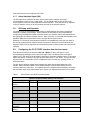
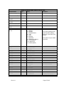
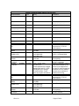
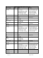
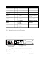
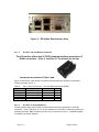
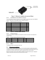
Appendix G5 G.703/E1 Interface PSM-500 Series G.703/E1 Interface Addendum Revision History Rev 0.10 2-1-2012 Rev 0.11 5-2-2012 Corrected E1 transport stream descriptions. Corrected front panel menu entries. 1.0 Initial Release. Optional G.703/E1 Interface Overview G.703/E1 is a legacy interface standard that is used in Telephony and Cellular Backhaul applications. The installation of the optional G5 (G.703/E1) interface provides the M500 Class modems (PSM-500/500L/500LT) with an economical access solution for E1 and Fractional E1 network services over satellite. The G5 fully meet all of the E1 rate 2048 kbit/s specifications including ITU recommendations: G.703 - Physical/electrical characteristics of hierarchical digital interfaces. G.704 - Synchronous frame structures used at 1544, 6312, 2048, 8448 and 44 736 kbit/s hierarchical levels. G.706 - Frame alignment and cyclic redundancy check (CRC) procedures relating to basic frame structures defined in Recommendation G.704. G.732- Characteristics of primary PCM multiplex equipment operating at 2048 kbit/s. G.823 - The control of jitter and wander within digital networks which are based on the 2048 kbit/s hierarchy. NOTE: If the G5 interface card is not already installed in the modem refer to Section 4 for installation information. Typical use of the G5 interface is in a duplex point to point link with a similarly configured PSM500 series modem at the other end of the link. The setup of the satellite link is very simple because the modems at both ends of the link are connected to DTE equipment with this same G.703/E1 interface type. Each port of the G5 interface can be configured independently for either Full E1 or Fractional E1 operation. The Full E1 mode allows for transmission of an the 2.048Mbps input data stream without synchronizing to the imbedded framing of the E1 signal. In this case the port data rate though the satellite link is the full 2.048Mbps of the E1 transport stream. Note in Unframed E1 there is no requirement for G.704 framing. The Fractional E1 mode allows for data rates of Nx64kbps to be transmitted over the satellite. The G5 interface has flexible selection the number of timeslots to be transmitted and for selection of standard signaling formats. PCM30-CAS (Channel Associated Signaling) (Nx64Kbps, N = 1 to 15, 17 to 31 TS). PCM31-CCS (Common Channel Signaling) (Nx64Kbps, N = 1 to 31 TS). The FullE1 or Fractional E1 modes are controlled via the G.703 Frame parameter. Any combination of Full E1 or Fractional E1 can be used independently on each port, and can be used independently on the transmit or receive side of each port. Rev 0.11 Page G.703-1 Key Features Single or Dual port G.703/E1 Unframed & Fractional E1 operation Data rate: User selectable N x 64Kbps in PCM30-CAS or PCM31-CCS modes Fully transparent signal conversion under unframed mode Clock Regeneration from incoming HDB3 or AMI formatted data CRC4 ON/OFF modes. Diagnostic Loopbacks for both Terrestrial and Satellite side E1 alarm monitoring for all common E1 transport stream alarms: LOS - Loss Of Signal. (All Modes) AIS - All 1's at input port. (All Modes). LFA - Loss of Framing Alignment. (PCM30-CAS and PCM31-CCS). LMFA - Loss of Multi-Frame Alignment. (PCM30-CAS only). RAI - Remote Alarm Indication. (PCM30-CAS and PCM31-CCS). TS16AIS - All 1's in TS 16. (PCM30-CAS only). The G5 G.703/E1 interface is only available for PSM-500 Series of modems, either new or as an upgrade to existing customer modems. This optional Interface card is designed to be installed in the option interface position inside the main modem assembly. 2.0 Technical Specifications: 2.1. E1 Signal Structure The G.703/E1 interface operates at a nominal rate of 2.048Mbps. The data transferred over the E1 transport stream is organized in frames. Each E1 frame contains 256 bits which are comprised of 32 timeslots, each containing eight bits. The data rate of each timeslot is 64Kbps. For 8-bit PCM encoded voice audio, each timeslot provides for an 8 kHz sampling rate. Timeslot 0 is used for frame synchronization and alarms. Timeslot 16 is used for signaling, alarms, or data. Timeslot 1 to 15 and 17 to 31 are used for carrying data or PCM encoded voice audio. There are two E1 frame formats, Normal frame (PCM31-CCS) Multi-frame (PCM30-CAS) Framing is necessary in order for equipment receiving the E1 signal to identify timeslot alignment and extract or insert the proper data. E1 signals configured with the PCM31-CCS format use the frame alignment signal (FAS) for synchronization. When the PCM30-CAS format is used the multi-frame alignment signal (MFAS) is used along with the FAS. The multi-frame structure also provides channel associated signaling (CAS) for PCM30. There is also an optional a cyclic redundancy check (CRC) in both PCM30-CAS and PCM31-CCS modes that is used to detect errors in the data stream.Frame Alignment Signal (FAS) Rev 0.11 Page G.703-2 Timeslot 0 of every other frame is reserved for the FAS. Alternate frames contain the FAS Distant Alarm indication bit and others bits reserved for national and international use. 2.1.1. Multi-Frame Alignment Signal (MFAS) MFAS framing provides Channel Associated Signaling (CAS) that transmist A/B/C/D bit signaling information for each of 30 channels in timeslot 16. This method uses the 32 timeslot frame format with timeslot 0 for the FAS and timeslot 16 for the MFAS and the CAS. 2.1.2. Channel Associated Signaling (CAS) When timeslot 16 of the E1 frame is used for Channel Associated Signaling (CAS) purposes, frame 0 contains the MFAS and timeslot 16 of frames 1-15 is used to convey the state of the A,B,C and D signaling bits. NOTE: The ABCD state of 0000 is not allowed. If all bits in timeslot 16 are 0, a loss of the MFAS can be assumed. When A-Bit only signaling is used (No BCD bits), the BCD bits should be fixed at: B=1, C=0, D=1 (101). A detection of all 1's in timeslot 16 declares a TS16AIS alarm, which indicates a remote alarm with the upstream E1 equipment. 2.1.3. Common Channel Signaling (CCS) When Common Channel Signaling (CCS) is employed, G.704 allows for various types of signaling information to be carried in any timeslot, therefore timeslot 16 is available for user or bearer data. Common channel signaling (CCS) is signaling in which a group of voice-and-data channels share a separate channel that is used only for control signals. This signaling protocol can be SS7, ISDN, or PBX/Switch Proprietary protocols. The channel used for common-channel signaling does not carry user information. 2.1.4. E1 Line Coding The basic E1 signal is coded using the Alternate Mark Inversion (AMI) or High-Density Bipolar 3 (HDB3). In AMI coding, “ones” are alternately transmitted as positive and negative pulses, whereas “zeros” are transmitted as a zero voltage level. AMI is not used in most E1 transmissions because synchronization loss will occur during long strings of data zeros. In HDB3 coding, a string of four consecutive zeros is replaced with a substitute string of pulses containing an intentional bipolar violation. The HDB3 code substitutions provide high pulse density so that the receiving equipment is able to maintain synchronization with the received signal. The G5 supports two E1 link line codes: AMI coding HDB3 coding. 2.1.5. E1 Cyclic Redundancy Check (CRC) The ITU standard describes an optional implementation where a 4-bit Cyclic Redundancy Check (CRC4) can be used to provide error detection for Frames 0 through 7, and Frames 8 through 15. When this CRC4 format is used, the even frame’s International Bit is replaced with a CRC-4 bit. The National Bits are relabeled as spare bits. The G5 interface allows for the CRC4 function to be Enabled or Disabled. 2.1.6. Other Interface Specifications Balanced: 120 ohm impedance on a RJ48c Unbalanced: 75 ohm impedance using an external 120 ohm to 75 ohm converter (i.e. Balun-B2S) Rev 0.11 Page G.703-3 Jitter performance is in according to ITU G.823 2.1.7. Alarm Indication Signal (AIS) The AIS signal is an unframed “all-ones” signal, and is used to maintain line signal synchronization in case of loss of input signal. The G5 interface will provide an AIS on the receive data line if there is a fault condition in the demodulator. There will also be an indication on the G5 interface if there is an AIS condition received on the transmit data line. 3.0 G5 Setup and Operation The addition of a the G5 interface card provides G.703/E1 physical and electrical interfaces designed to operate at 2.048 Mbps. When installed, the G5 interface card is automatically recognized by the PSM-500 modem controller and the user interface menus are populated with the appropriate G5 interface selection menu’s. Refer to Section 3 in the PSM-500 Installation and Operation Manual for instructions on how to navigate the front panel menus. Selection of G.703 as the currently active interface is accomplished by using the front panel or the remote control protocols. Refer to Section 2.2 below for operation via the front panel and Appendix B (Rev-0.96 or higher) for the remote protocol that is used to select and control the G5 interface. 2.2. Configuring the G5 G.703/E1 Interface from the front panel. From the front panel you would select <Intf: I/O – Mode> for the G.703 option. This is accomplished by pressing the Int’f button to the right of the LCD display, then scroll right to display “I/O” in the upper left of the display, and down if necessary to display “Mode” in the upper right of the display. To select G.703 you can then either press “?” and “Enter”, or press the “Edit” key and scroll up or down until “G.703” is displayed in the LCD lower line, pressing “Enter” to select that option. The G5 has the ability to perform local loopback from either the terrestrial data side or the satellite. When used with a BERT, the terrestrial loopback function allows testing of the E1 interface cables and connectors. IF Loopback allows for compete modem testing by connecting the modulator output to the demodulator input. Section 3.2 describes these tests in more detail. Table 1 G5 Interface Front Panel Parameter Details Interface Parameter Detail (when G.703 is Active) Type Entry Description Representation Status Online Status Off Status On Status On Status Off Status Off Status Mod BER Status 0.0 E-7 Rev 0.11 I/O Read Only N/A Interface Status ** RTS Read Only N/A Interface RTS line status CTS Read Only N/A Interface CTS line status DCD Read Only N/A Interface DCD line status DTR Read Only N/A Interface DTR line status DSR Read Only N/A Interface DSR line status Test Read Only N/A Interface Test status BER Read Only N/A Interface Test status Page G.703-4 Interface Parameter Detail (when G.703 is Active) Type Entry Description Representation Status 3 Status 7 Status 1.45 E7 Status 99.95% Status 1 Status 2135 SyncLoss Read Only N/A Interface Test status Errors Read Only N/A Interface Test status Bits Read Only N/A Interface Test status EFS Read Only N/A Interface Test status ErredSec Read Only N/A Interface Test status TotalSec Read Only N/A Interface Test status Selection 0 = Disable 1 = RS-232 2 = RS-449 3 = RS-449/Unterm 4 = V.35 5 = V.36 6 = EIA-530 7 = EIA-530A 8 = Ethernet IP (Option) 9 = G.703(Option) 10 = (Reserved) 11 = HSSI (Option) Interface electrical mode. 0 = Normal 1 = Control CXR 2 = Ignore 0 = Normal, 1 = Force Active 0 = Normal, 1 = Force Active 0 = Normal, 1 = Ignore 0 = Normal, 1 = Force Active 0 = Normal, 1 = Inverted 0 = Normal, 1 = Inverted, 2 = Auto 0 = Normal, 1 = Inverted 0 = Normal, 1 = Inverted 0 = Disabled, 1 = to Alarm A, 2 = to Alarm B Interface RTS line control I/O G.703 Mode I/O Ignore RTS Selection I/O Normal I/O Normal I/O Normal I/O Normal I/O Normal I/O Normal CTS Selection DCD Selection DTR Selection DSR Selection XmtData Selection XmtClock Selection RcvData Selection RcvClock Selection RTSMonitor Selection I/O Normal I/O Normal I/O Normal Rev 0.11 Some option interfaces may replace the SnIP, HSSI or Ethernet IP, and Dual G.703 interface. Other options may be added in the future. Interface CTS line control Interface DCD line control Interface DTR line control Interface DSR line control Transmit Data Inversion Transmit Clock Phase. Auto is now default standard. Receive Data Inversion Receive Clock Phase Allows using Alarm relay contacts to show RTS Status, overriding other alarms. Page G.703-5 Representation Interface Parameter Detail (when G.703 is Active) Type Entry Description For Advanced I5 Option Only IIP Mode Type IIP IPAddr 192.168.100.1 IIP NetwrkMask 255.255.255.0 IIP MACAddr 0080A800256C IIP Options 00007f IIP Version 021771-001-50 IIP Serial# 1000047 Selection G703P1 E1 Read Only Numeric Numeric Read Only Read Only Read Only Read Only Read Only Read Only Read Only Read Only TxMode Selection 1=E1 G703P1 TxCode HDB3 G703P1 TxFrame PCM31-CCS Selection G703P1 Enable G703P1 512 kbps G703P1 TS08-On TxCRC4 Selection 0=AMI 1=HDB3 0=Full E1 1=PCM30-CAS 2=PCM31-CCS 0=Disable 1=Enable TxNx64k Read Only DropMap Selection TSxx – 0=Off, 1=On. xx = 01 to 31. Press Up/Down key to toggle between Off and On. Press Left/Right keys to change Timeslot number. Press enter to program all timeslots. RxMode Selection 1=E1 G703P1 RxCode HDB3 G703P1 RxFrame PCM31-CCS Selection G703P1 Enable G703P1 512 kbps RxCRC4 Selection 0=AMI 1=HDB3 0=Full E1 1=PCM30-CAS 2=PCM31-CCS 0=Disable 1=Enable RxNx64k Read Only G703P1 E1 Rev 0.11 Selection Selection Displays type of IP interface present (I5, SnIP, etc.) IP Address for Ethernet IP Interface. IP Mask Address for Ethernet IP Interface. Allows read of fixed Interface MAC Address.. Displays Ethernet IP Options enabled Displays Ethernet IP Software Version Number Displays Ethernet IP Serial Number G.703/E1 interface Port 1 always active if G.703 IO Mode selected. Line Coding selection. Input Framing selection; Full E1 = Unframed Mode. Cyclic Redundancy Check for error reporting. Nx64kbps fractional E1 rate for Port 1 transmitter. Used for FractionalE1 mode to select which timeslots (1-31) that are to be dropped from the input E1 framed signal and transmitted over the satellite. Timeslot 16 not available in PCM30-CAS framing. G.703/E1 interface Port 1 always active if G.703 IO Mode selected. Line Coding selection. Output Framing selection Cyclic Redundancy Check for error reporting Nx64kbps fractional E1 rate for Port 1 receiver. Page G.703-6 Interface Parameter Detail (when G.703 is Active) Type Entry Description Representation InsMap Selection TSxx – 0=Off, 1=On. xx = 01 to 31. Press Up/Down key to toggle between Off and On. Press Left/Right keys to change Timeslot number. Press enter to program all timeslots. Used for FractionalE1 mode to select which timeslots (1-31) that are to be inserted to the output E1 framed signal received over the satellite. Timeslot 16 not available in PCM30-CAS framing. G703P2 TxMode E1 G703P2 TxCode HDB3 G703P2 TxFrame PCM-31-CCS Selection Activate the G.703/E1 interface Port 1 Line Coding G703P2 PCM-31 G703P2 512 kbps G703P2 TS08-On TxCRC4 Selection 0=Disable 1=E1 0=AMI 1=HDB3 0=Full E1 1=PCM30-CAS 2=PCM31-CCS 0=Disable 1=Enable TxNx64k Read Only DropMap Selection TSxx – 0=Off, 1=On. xx = 01 to 31. Press Up/Down key to toggle between Off and On. Press Left/Right keys to change Timeslot number. Press enter to program all timeslots. RxMode Selection RxCode Selection RxFrame Selection G703P2 RxCRC4 PCM-31-CCS G703P2 RxNx64k 512 kbps G703P2 InsMap TS08-On Selection 0=Disable 1=E1 0=AMI 1=HDB3 0=Full E1 1=PCM30-CAS 2=PCM31-CCS 0=Disable 1=Enable Selection TSxx – 0=Off, 1=On. xx = 01 to 31. Press Up/Down key to toggle between Off and On. Press Left/Right keys to change Timeslot number. Press enter to program all timeslots. Cyclic Redundancy Check for error reporting Display the Nx64kbps satellite rate Used for FractionalE1 mode to select which timeslots (1-31) that are to be inserted to the output E1 framed signal received over the satellite. Timeslot 16 not available in PCM30-CAS framing. Alarm to Alarm A Alarm to Alarm B TstActive Selection 0=None, 1=A, 2=B, 3=A & B Selects destination of alarm BERLoss Selection 0=None, 1=A, 2=B, 3=A & B Selects destination of alarm G703P1 TS08-On Port 2 Selection Selection Input Framing selection Cyclic Redundancy Check for error reporting Display the Nx64kbps satellite rate Used for FractionalE1 mode to select which timeslots (1-31) that are to be dropped from the input E1 framed signal and transmitted over the satellite. Timeslot 16 not available in PCM30-CAS framing. Port 2 G703P2 E1 G703P2 HDB3 G703P2 PCM-31 Rev 0.11 Read Only Activate the G.703/E1 interface Port 1 Line Coding Input Framing selection Page G.703-7 Interface Parameter Detail (when G.703 is Active) Type Entry Description Representation Alarm to Alarm A Alarm to Alarm Alarm to Alarm A Enet Selection 0=None, 1=A, 2=B, 3=A & B Selects destination of alarm E1-Port1 Selection 0=None, 1=A, 2=B, 3=A & B Selects destination of alarm E1-Port2 Selection 0=None, 1=A, 2=B, 3=A & B Selects destination of alarm Test Disabled TerLoopbck Selection 0 = Disable 1 = Enable Test Disabled SatLoopbck Selection 0 = Disable 1 = Enable Test Satellite Test Disabled BERI/O Selection ModBER Selection DemodBER Selection 0 = Satellite 1 = Terrestrial 0 = Disable 1 = 2047 2 = 2^23-1 3 = Insert 1 Error (if enabled) 0 = Disable 1 = 2047 2 = 2^23-1 Interface terrestrial loop-back Send Data input to Receive Data output. Interface satellite loop-back demodulator output to modulator input. BERT Function. See Main User Manual for Description BERT enable to modem transmit input. Test Disabled 2.3. BERT enable from modem receive output. Making Connections to the G5 Interface Figure 1 shows the rear interface panel of the PSM-500 series modem with the G5 optional interface installed. AC Line S1 G.703 E1/T1 GbE - IP P1 GI-5 Interface AUX J4 Console Control J2 P2 J5 Alarm J3 Data Interface J6 Control J1 90 - 260 VAC, 50 W. No Connection with G5 Only Option G5 Option Interface P1 and P2 Figure 1 - PSM-500 rear panel G5 Interface Location 2.3.1. G5 Connections The G5 interface has five (5) user interface connectors on the rear panel of the optional card. Refer to Table 2 through Table 4 for the connector type, signal names, and connector pinouts. Rev 0.11 EXT. REF J7 Page G.703-8 Figure 2 – G5 Option Rear Interface View 2.3.1.1. G.703/E1 120 ohm Balanced Interface The G5 interface offers dual G.703/E1 balanced interface presented on 2 RJ48c connectors – (Port 1) and (Port 2). The pinouts for the two connectors are shown in Table 2 and Figure shows picture of the interface connectors using a balanced (120ohm) to unbalanced (75ohm) converter on Port 1. Table 2 Port 1 & Port 2 Connector – 120 ohm Balanced Pinouts (RJ48c) Signal Name Description Direction Pins SD-T Send Data Tip To Modem 1 SD-R Send Data Ring To Modem 2 RD-T Receive Data Tip From Modem 4 RD-R Receive Data Ring From Modem 5 GND Ground n/a 3,6 2.3.1.2. G.703/E1 75 ohm Unbalanced The G5 interface offers dual G.703/E1 120 ohm balanced interface presented on 2 RJ-48c connectors – (Port 1) and (Port 2). For 75 ohm unbalanced connections, a balanced (120ohm) to unbalanced (75ohm, BNC) converter must be used, like shown in Figure 3. This Balun adapter is available from Datum Systems. Rev 0.11 Page G.703-9 75 Ohm, BNC Unbalanced I/O 120 Ohm, RJ-48 Balanced I/O Figure 3 - Balanced to unbalanced converter (Balun) 2.3.1.3. 10/100 Ethernet (via the GbE- IP Connection) The 10/100 Ethernet interface connector is used for SNMP control and monitor of the PSM-500 modem. Please refer to SnIP SNMP Guide for support information. Table 3 GbE-IP Connector Pinouts (RJ45) Name Description Transmit Data+ TX D1+ Transmit DataTX D1RX D2+ Receive Data+ BI D3+ Bi-directional pair C + BI D3Bi-directional pair C RX D2Receive DataBI D4+ Bi-directional pair D + BI D4Bi-directional pair D - Pin 1 2 3 4 5 6 7 8 Figure 4 - Ethernet SNMP interface 2.3.1.4. Console Connector The console connector is available for command line control and monitor of the Optional G5 processor card. Table 4 Console Connector Pinouts (9 pin D female) Signal Name Description Direction Pins RXD Console RX From Modem 2 TXD Console TX To Modem 3 GND Ground 5 2.3.1.5. Notes EIA 232 EIA232 USB2.0 The USB2.0 interface is reserved for future use. 3.0 G5 Interface Installation The G5 interface is normally factory installed, but can be field installed by technical personnel. The option card itself is an approximate 3.5-inch by 7.25 inch printed circuit board designed to be mounted in the interface option position inside the PSM-500 series modem chassis. Remove the modem unit from service before installation of the G5 Interface option. Unplug the modem unit and remove the power cord from the rear for safety. Rev 0.11 Page G.703-10 Place the unit on a flat surface and remove the 8 flathead screws holding the cover to the main chassis using a number 2 Philips screwdriver. The location for the option card installation is shown in Figure below. WARNING: Failure to remove power from the modem unit before removal of the cover can expose the operator to hazardous voltages and result in harm to personnel and equipment. 3.1. Installing the G5 Interface Position the rear option plate supplied into the chassis and align the mounting plate holes with the holes in the chassis rear panel. Just start inserting the two #4 pan head screws without lock washers to hold the plate in place. Slide the G5 interface assembly into the chassis and line up the connectors with its opening on the rear plate. Slide the interface back and align the card’s standoffs with the 4 standoffs in the chassis. Figure 5 - G5 Interface Installation Rev 0.11 Page G.703-11 Mount the G5 card to the chassis using the 4 #6 mounting screws with lock washers. An additional flat washer may be required to keep the PCB mounting screws from extending beyond the chassis bottom. Tighten the rear plate mounting screws and then the PCB mounting screws. Connect the upper 40 pin ribbon cable connector to the main PCB header and press down to close the latches. Care must be taken to avoid bending the installed FEC card which is very close to one latch. Re-install the cover and plug the unit in. Using the front panel arrow keys scroll down to the interface parameter and verify that the modem recognizes the newly installed card. The modem is now ready to be put into service. 3.2. Physical Connectivity Tests The following tests will verify the proper installation and performance of the G5 card within the PSM-500 modem. Connectivity and performance will require the use of a Bit Error Rate Tester (Fireberd or similar) with an E1 and/or Fractional E1 interface. 3.2.1. Local Loopback This first test checks the local interfaces and cable and does not require a satellite link or other earth station equipment. The G5 interface will loopback the transmit input data back out on the receive data port by using the Local Loopback settings on the front panel <Intf:Test> menu. Refer to the front panel configuration menus in the PSM-500 I&O Manual and Table 1 above for setup information of all the modem functions. Table 5 shows the menu selection for enabling the local terrestrial loopback function. Table 5 Front Panel Terrestrial Loopback menu Function Type Entry Test TerLoopbck Selection 0 = Disable1 = Enable Enable Description Interface terrestrial loop-back Send Data input to Receive Data output. Verify that the BER tester is able to achieve data synchronization and there are no errors. Once the test is finished, remove the test mode by setting the TerLoopbck to Disable. 3.2.2. Modem IF Loopback If the Local Loopback test passed, then test the performance of the G5 interface within the PSM500 modem. The test setup for this test is shown in Error! Reference source not found.. The PSM-500 modem will loopback the Modulator TX IF Output back to the Demodulator RX IF input by using the Local Loopback settings on the front panel <Dem:Test> menu. Refer to the front panel configuration menus in the PSM-500 I&O Manual and Table 1 above for setup information of all the modem functions. Table 6 shows the menu selection for enabling the IF Loopback function. Table 6 Front Panel IF Loopback menu Function Type Test IFLoopbck Selection Enable Rev 0.11 Entry 0 = Disable 1 = Enable Description IF Loop-back control. Page G.703-12 Verify that the BER tester is able to achieve data synchronization and there are no errors. Once the test is finished, remove the test mode by setting the IF Loopbck to Disable. The unit is now ready for normal operation. Rev 0.11 Page G.703-13