1
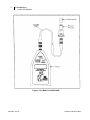
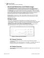
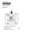
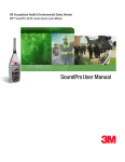
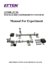
3M Occupational Health & Environmental Safety Division 1100/2100 Sound Level Meter Models Easy to Use Functionality 1100/2100 SLM User Manual 1100/2100 Sound Level Meters Owner’s manual Note: Due to the new ATEX Directive in Europe, all references in this document to "Ex" or "EEx" for intrinsic safety approvals should be disregarded effective 7/1/03 within the member countries of the European Union (EU). At this time, this product is not approved in accordance with the new ATEX Directive and is not sold for use in hazardous atmospheres or explosive zones by customers within the EU. Outside of the EU, all references to intrinsic safety continue without change. Introduction The 1100 Sound Level Meter is a light weight easy-to-use Type 1 instrument. The 2100 is a Type 2 model. The purpose of this manual is to provide you with the necessary information to operate the 1100/2100 Sound Level Meter as well as the remote-able versions of the 1100R/2100R. The entire manual should be read to fully understand the many features this instrument offers. Copyright This document is copyrighted by Quest Technologies, a 3M company. Permission is hereby granted to copy and distribute this manual provided that this Copyright Page is included. This grant does not include permission to modify the manual’s text or illustrations in any way. This manual may not be translated without obtaining permission in advance. Trademarks Quest Technologies, the Quest logo, and QuestSuiteTM Professional II are registered trademarks of Quest Technologies Incorporated. All rights are reserved. Microsoft and Windows are registered trademarks of Microsoft, Inc. Updates In the interests of continuous product improvements, Quest Technologies reserves the right to make changes to product specifications without notice. To understand the latest updates that have been implemented into this product and to download the most current version of this user manual, visit our web site at www.quest-technologies.com. Copyright © 2011 Quest Technologies, a 3M company 056-652, Rev.D 1100/2100 SLM models ii Table of Contents Table of contents Introduction ...................................................................................................................... 1 1100/2100 Models .............................................................................................................. 1 Getting Started ................................................................................................................. 3 The Display ........................................................................................................................ 3 Meter Controls .................................................................................................................... 3 OFF/SPL/MAX Switch..................................................................................................... 3 "F" (FAST) / "S" (SLOW) RESPONSE Switch .................................................................. 3 Overload Detection and Underrange .................................................................................. 5 Output Jack ........................................................................................................................ 5 DC Output Function ....................................................................................................... 5 AC Output Function ........................................................................................................ 5 Checking the battery ........................................................................................................ 6 Battery Check ..................................................................................................................... 6 Battery Replacement .......................................................................................................... 6 Rechargeable Batteries ...................................................................................................... 6 Calibrate ............................................................................................................................ 6 Changing the Calibration Level ........................................................................................... 6 Calibration .......................................................................................................................... 7 Calibration Check ............................................................................................................... 7 Operating and Measurements ......................................................................................... 8 Operation ........................................................................................................................... 8 Meter/Microphone Placement ............................................................................................. 8 Background Noise .............................................................................................................. 8 Background Noise Example ............................................................................................... 9 Windscreen Effects............................................................................................................. 9 Chart Recording/Datalogging ........................................................................................... 10 Technical Information .................................................................................................... 11 Principles of Operation ..................................................................................................... 11 Microphone ...................................................................................................................... 12 Microphone response time ............................................................................................... 12 Microphone preamplifier extension cables ........................................................................ 13 Input Buffer Circuitry ......................................................................................................... 13 056-652, Rev.D 1100/2100 SLM models iii Table of Contents Weighting Characteristics ................................................................................................. 14 Internal Electrical Noise .................................................................................................... 14 Tone Burst Response ....................................................................................................... 15 Specifications ................................................................................................................. 16 Accessories .................................................................................................................... 18 Quest Service ................................................................................................................. 19 Contacting Quest Technologies ........................................................................................ 19 International customers .................................................................................................... 19 Figures Figure 1-1: Figure 1-2: Figure 2: Figure 3: Figure 4: Figure 5: Figure 6: Figure 7: Figure 8: Figure 9: Figure 10: Figure 11: Figure 12: Figure 13: Sound Level Meter 2100 model ....................................................................1 Model 1100R/2100R....................................................................................2 Keypad/Control switches identified ...............................................................4 Output jack connections...............................................................................5 Effects of background noise...........................................................................9 Effects of WS-7 ...........................................................................................9 Block diagram of the model 1100/2100’s circuit board.................................. 11 Typical microphone response Type 1 ......................................................... 12 Typical microphone response Type 2 ......................................................... 12 Frequency/Amplitude limitations with extension cables ................................ 13 Input buffer circuitry ................................................................................... 13 A & C Weighting ........................................................................................ 14 Fast response ........................................................................................... 15 Slow response .......................................................................................... 15 056-652, Rev.D 1100/2100 SLM models 1 Introduction Introduction 1100/2100 Models Introduction The Quest models 1100 and 2100 Sound Level Meters and their remote versions (1100R/2100R) measure frequency weighted and time averaged sound pressure level and are shown in Figures l-1 and 1-2. Applications include laboratory, industrial, community, military, and audiometric measurement or analysis. 1100/2100 Models The models 1100 and 2100 are easy-to-use hand held meters with an LCD display that provides a numerical readout. They are housed in a rugged RF shielded, injection molded case. The meters are operated with simple slide switches. An output jack is provided for connecting to peripheral devices such as chart recorders, oscilloscopes, audio recorders, etc. The model 1100 provides Type 1 accuracy for critical measurements, while the model 2100 provides Type 2 accuracy for general field survey work. As both meters are operationally identical, this manual will refer only to the model 1100 except where appropriate. Microphone Fixed Preamp Housing for the 1100 is longer than 2100 Display of the 2100 model Figure 1-1: Sound Level Meter 2100 model 056-652, Rev.D 1100/2100 SLM models 2 Introduction 1100/2100 Models Figure 1-2: Model 1100R/2100R 056-652, Rev.D 1100/2100 SLM models 3 Getting Started Getting Started The Display Getting Started The Display The LCD display provides a numeric readout of sound level in 0.1 dB increments along with a LOBAT (low battery) indicator. In the SPL mode the numeric display provides a reading of the maximum sound pressure level measured during the previous second. In the MAX mode the display holds the highest reading encountered since the meter was placed in MAX, or since the last time RESET was pressed. The LOBAT indicator will light when the battery voltage is too low to allow an accurate reading. The display will show a + sign when signal peaks cause an overload condition in the electronics. This indicator signals the user to switch to the next higher range to prevent erroneous readings. The display will show "Ur" if signal levels are too low to provide an accurate reading. This indicator signals the user to switch to a lower range setting. Meter Controls OFF/SPL/MAX Switch With the switch set to SPL the meter continuously displays sound level, automatically updating the current reading at a rate of once per second. Setting the switch to MAX causes the display to hold the highest SPL encountered thus far. As a higher SPL occurs, the display changes to show the new value. To reset the value stored, press and hold the RESET button for a few seconds, then release. This will erase the previous MAX value (and display the current value) prior to taking new readings. For response times see Figures 7 and 8. "F" (FAST) / "S" (SLOW) RESPONSE Switch The RESPONSE switch controls the rate at which the meter responds to changing input signals. Most sound measurements are done with the response set to SLOW. The FAST response is generally used when measuring short duration noises such as moving vehicles. The RESPONSE switch positions are as follows: • FAST - 125 millisecond time constant. (See Figure 12). • SLOW - 1 second time constant. (See Figure 13). 056-652, Rev.D 1100/2100 SLM models 4 Getting Started Meter Controls WEIGHTING A/C Switch The WEIGHTING switch controls the frequency response of the meter. Weightings A or C may be selected. See “Microphone preamplifier”, page 13 Weighting Characteristics, for further information. RANGE (dB) Switch The displayed range of the model 1100 is 70 dB and is switchable between 30-100 dB, 50-120 dB, and 70-140 dB. After switching ranges allow several seconds for the meter electronics to stabilize. RESET Button This button is primarily used to clear the MAX sound level when the instrument is in the MAX mode. Pressing the RESET button for at least a half second will cause a reset of MAX. If observation of the changing Sound Pressure Level is desired, while in the MAX mode, the RESET button may be held down for as long as the SPL display is desired. Upon release of the RESET button MAX will be reset and the 1100 will resume accumulating MAX. The RESET button also functions as an up arrow during setup (see “Changing the Calibration Level”, page 6). CAL Button This button is primarily used to enter the Calibration routine, but it also functions as a down arrow during setup (see “Changing the Calibration Level”, page 6). Weighting A or C Response Fast or Slow Range 30 to 140 dBA Measurement SPL or MAX Figure 2: Keypad/Control switches identified 056-652, Rev.D 1100/2100 SLM models 5 Getting Started Overload Detection and Underrange Overload Detection and Underrange The Overload Indicator is displayed whenever the incoming signal saturates (overloads) the circuitry. It is the + sign on the left side of the display. If the overload indicator is on while taking measurements in a Low range, increasing the dB Range switch should cause the overload to disappear. If you are already on the highest range setting and an overload condition still exists, the sound level that you are measuring is beyond the capability of the 1100 due to either an extremely high rms value or a high crest factor (peak to rms ratio). Underrange is indicated by a "Ur" in the display. When the noise level drops below the bottom of the range, this indicator will turn on. Switching to a lower range will turn it off. Output Jack The model 1100 provides an output jack on the bottom of the meter for measuring the weighted AC signal before the rms/log detector and the DC output of that detector. This jack may be connected to any load without affecting the operation of the meter. Connection to low impedance loads will require correction for the 1 Kohm impedance of this output and will also decrease battery life. The output jack uses a 3.5mm stereo plug. Figure 3: Output jack connections DC Output Function The Sound Pressure Level (SPL) over the range selected is linearly represented by a DC output. The output changes 16.7mV/dB or 1 V/60dB. This output is primarily provided for connecting a 0 to 1 volt span data recorder. AC Output Function This output provides the amplified, weighted AC signal from the input of the RMS detector. 056-652, Rev.D 1100/2100 SLM models 6 Checking the battery Battery & Calibrate Battery Check Checking the battery Battery Check At any time other than initial turn on, if the LOBAT indicator on the display is activated the user must replace the battery. A 9 volt Alkaline battery is recommended for best performance. Refer to the label in battery compartment for battery replacement. Battery Replacement Slide the battery door to the left to open the battery compartment and refer to the label inside the compartment for proper battery orientation. Rechargeable Batteries Nicad type rechargeable 9 V batteries (such as Radio Shack® 23-299 7.2 V, 120 mAh) and an appropriate charger may be used with the 1100. The fact that nicad 9 V replacement cells typically operate at 7.2 V will be observed as shorter battery life (approximately 8 hours with Radio Shack® 23-299). At the appearance of the LOBAT indicator the nicad battery must be recharged. NiMH (Nickel-MetalHydride) batteries are NOT recommended. This is due to the excessive discharge of the typical NiMH cell prior to the voltage dropping low enough to activate the LOBAT indicator. Calibrate Changing the Calibration Level NOTE: There may be times when it is necessary to change the calibration level that is stored in the meter. This calibration level is the decibel level that is produced by your calibrator. 1. Changing Cal level Turn on the meter. The display will show: a. All segments for 2 seconds. b. The meter revision number for 2 seconds. c. The current calibration level stored in the meter for 5 seconds. 2. While current calibration level is in the display, press and hold both the RESET and CAL buttons for at least 1/2 second or until dashes appear in the display. Release the RESET and CAL buttons. The meter is now in the calibration level set mode. 056-652, Rev.D 1100/2100 SLM models Checking the battery 7 Calibration NOTE: If the RESET and CAL buttons are continuously held down after the dashes appear, the unit will interpret this as a command to exit calibration level set mode and exit without changing the calibration level. 3. To edit the level, use the RESET key to increase the value and the CAL key to decrease the value. Edit the value to match your calibrators output. 4. When the desired calibration level is displayed, press and hold both the RESET and CAL buttons until dashes appear on the display. The new calibration level is now stored in the instrument's memory and will not have to be changed again unless an alternate calibrator is used. Calibration The model 1100 may be calibrated in any range based on your calibrator's output. There is no warm up period required, but for maximum accuracy calibration of the model 1100 should be performed at the temperature of the environment to be measured. To calibrate, perform the following procedure using a Quest calibrator. It is recommended that calibration be performed before each use. Calibration 1. Check to see that the LOB AT indicator is not on. 2. Check to see that the calibrator SPL output matches the calibration level stored in the meter. If it does not, use procedure outlined in “Changing the calibration level” NOTE: Failure to match calibrator output level to calibration level stored in the 1100 will result in erroneous SPL reading. 3. Turn the calibrator ON. If optional, set the frequency to 1 KHz. 4. Place the black adapter ring fully onto the microphone. 5. Set the model 1100 to SPL, SLOW or FAST, and A or C weighting. Set the measuring range so that the calibration level falls within it. NOTE: Attempting to calibrate out of range will result in an "Err" on the display and a failed calibration. The previous calibration data will remain in the instrument. 6. Press the CAL button. “CAL” will appear on the display followed by moving dashes. After about 2 seconds the display will show either a "P" for pass or an "F" for fail. If the calibration fails, check settings and repeat procedure. Calibration Check It is a good idea to check calibration after use. To do so, perform the previous steps 1 through 5. Observe the meter display, it should read the calibrator level +/- 0.5 dB. If out of tolerance, run calibration procedure described above in “Calibration”. 056-652, Rev.D 1100/2100 SLM models 8 Operating & Measurements Operating and Measurements Operation Operating and Measurements Operation Before taking measurements with the model 1100, there is a series of quick checks and considerations that should be performed or noted. After switching the unit ON, check for a LOBAT indication on the display, replace battery if necessary. (See “Battery check”, page 6). Although the model 1100 will maintain accurate calibration over a long period of time, the calibration should be checked and the meter re-calibrated, if necessary, before each use. The calibration should also be checked after each use. (See “Calibration check”, page 7). Set the RESPONSE, WEIGHTING, and RANGE (dB) switches as needed. Hold, set, or tripod mount the meter in the desired location. If a MAX measurement is needed, be sure to reset the meter before taking the measurements. It is always a good idea to document all measurement conditions and meter settings for possible future reference. Meter/Microphone Placement Whenever possible, the meter should be tripod-mounted in a relatively open area to minimize reflections from the body or other large reflective structures. Avoid placement against a wall or in a corner. A threaded bushing on the back will accept a standard 1/4-20 tripod fitting. The microphone cartridges used on the models 1100 and 2100 are free-field microphones. Point the meter directly at the noise source (0 degrees). Random incidence measurements may be taken with the 1100 if the plastic random incidence corrector supplied with the BK4936 microphone is used. The random incidence corrector is a black plastic lipped sleeve packed in the BK4936 packing container. To attach the corrector, position the end of the sleeve without the lip over the grid of the microphone and gently press down until a snap fit is achieved. Point the microphone approximately 70° to the direction of the sound. Background Noise Background noise can cause considerable error in measurement when its intensity is close to that of a particular sound source of interest. When it is not possible to eliminate or reduce the background noise, use the curve shown in Figure 4 to correct for the effect of the background noise on the measurement. 056-652, Rev.D 1100/2100 SLM models 9 Operating and Measurements Background Noise Example Background Noise Example For example, if the background noise is 45 dB and the sound of interest measures 51 dB, the difference between measurement and background noise is 6 dB. From Figure 4, for a 6 dB difference, 1.3 dB should be subtracted from the measurement. The correct measurement is therefore 51 dB- 1.3 dB= 49.7 dB. Figure 4: Effects of background noise Windscreen Effects To prevent measurement errors caused by wind blowing across the microphone, the use of a windscreen is recommended. The wind screen will reduce wind effects and will also help protect the microphone under dusty or oily conditions. Acoustic attenuation effects of the WS-7 windscreen are shown in Figure 5. Figure 5: Effects of WS-7 056-652, Rev.D 1100/2100 SLM models 10 Technical Information Operating and Measurements Chart Recording/Datalogging Chart Recording/Datalogging The model 1100 has a DC output that is linearly related to the decibel reading on the LCD display by 16.7mV/dB (1V/60dB). This output, capable of driving up to 100 feet of shielded or twisted pair cable, is intended for use with a 0 to 1 volt DC input chart recorder or data acquisition device that has a high input impedance. The output impedance is 1000 ohms. Chart recorder input impedance may cause loading of this output, which should be taken into account. Multiplication factors for the above numbers are given below for various chart recorder input impedances. Input impedance of recorder: 10 KOHM 20 KOHM 50 KOHM 100 KOHM 056-652, Rev.D Multiply DC voltage by: 1.100 1.050 1.020 1.010 1100/2100 SLM models 11 Technical Information Principles of Operation Technical Information Principles of Operation The Quest model 1100 uses low noise, low power analog and digital integrated circuitry to ensure long battery life, maximum stability, and superior reliability over a wide range of environmental conditions. Figure 6 is a block diagram of the model 1100/2100's internal circuit operations. v+ A Microphone PREAMP 1k WEIGHTING FILTER AC OUT C OVERLOAD DETECT FAST SLOW v+ RMS/LOG CONVERSION v- 1k LCD DISPLAY AC OUT MICROPROCESSOR A/O Converter vFigure 6: Block diagram of the model 1100/2100’s circuit board 056-652, Rev.D 1100/2100 SLM models 12 Technical Information Microphone Microphone The model 1100 is designed to accept a pre-polarized (electret) type 1 microphone Quest part number #059-523 BK 4936. The impedance of this microphone is approximately 12pF. The microphone screws directly onto either the remoteable preamp or the fixed microphone extension of the meter case. A typical response curve for the Type 1 microphone is shown in Figure 7. The model 2100 is designed to accept a prepolarized (electret) type 2 microphone Quest P/N #056-316 QE7052. The impedance of this microphone is approximately 15pF. The microphone screws directly onto either the remoteable preamp or the fixed microphone extension of the meter case. A typical response curve for the Type 2 microphone is shown in Figure 8. Microphone response time CAUTION: When installing or removing the microphone, do not unscrew the protective grid. Do not touch the metal foil microphone diaphragm under this grid as permanent damage may result. Figure 7: Typical microphone response Type 1 Figure 8: Typical microphone response Type 2 056-652, Rev.D 1100/2100 SLM models 13 Technical Information Microphone preamplifier extension cables Microphone preamplifier extension cables On 1100R (Remote) units the preamplifier is removable by unscrewing the black plastic collar below the preamplifier housing. The 1100 will drive up to a 10 foot cable with minimal loss. Quest offers the following lengths of remote cable for use with the 1100: • #59-899 ICM-2 Microphone Cable (2 foot length) • #59-733 ICM-10 Microphone Cable (10 foot length) • #59-734 ICM-50 Microphone Cable (50 foot length) The calibration level at 1 kHz is affected by less than 0.1 dB with the insertion of either of these cables. Therefore, there is no need to recalibrate when the cable is attached. Figure 9: Frequency/Amplitude limitations with extension cables Input Buffer Circuitry The high impedance input circuitry of the 1100 will accept up to a 2.0 volt RMS signal. With the microphone and preamp removed, other transducer devices may be connected to give a dB readout on the meter. To remove the preamplifier unscrew the black plastic collar below the preamp housing. Only use pins 1 and 3 for the AC signal input. NEVER connect to pins 2 and 4. To input an electrical signal requires a special connector, Quest part number 14-739. Figure 10 shows the function of each of the pins within the meter input connector. Figure 10: Input buffer circuitry 056-652, Rev.D 1100/2100 SLM models 14 Technical Information Weighting Characteristics Weighting Characteristics The weighting characteristics (frequency response) for A and C are shown in Figure 11. The "A" weighting response emulates the low level response of the human ear and is used for most industrial and community noise measurements. Generally, "C" weighting is used for measuring noise reduction in hearing protectors and for other scientific purposes. Figure 11: A & C Weighting Internal Electrical Noise The normal measurement range of the 1100 meter is approximately 30 to 140 dBA and 40 to 140 dBC. The inherent noise level is typically 24 dBA. 056-652, Rev.D 1100/2100 SLM models 15 Technical Information Tone Burst Response Tone Burst Response Figures 12 and 13 show the meter response to a sine-wave input of various pulse durations for Fast and Slow settings. Figure 12: Fast response Figure 13: Slow response Nominal decay times for each time response setting are as follows: • FAST - 34.7 dB per second • SLOW - 4.35 dB per second 056-652, Rev.D 1100/2100 SLM models Specifications 16 Specifications Tone Burst Response Specifications Standards: Model 1100 : Type 1 ; Model 2100 : Type 2 ANSI S1.4-1983(R1997), IEC 651-1979 EN60651 Display: 3 1/2 Digit Liquid Crystal Display. Level display indicates to 0.1 dB resolution. Annunciator is included for Battery Check. Modes of Operation: Measures sound pressure level (SPL) or maximum level (MAX). Linear Operating Range: 32 to 140 dBA 38 to 140 dBC Electrical Noise Floor: 25 dBA, 32 dBC typical Frequency Weighting Networks: A and C Meter Response: Slow and Fast Microphone: Removable .52 inch (13.5 mm) diameter prepolarized condenser (electret) microphone Model 1100 : - Type 1 accuracy (P/N: 059-523 BK 4936) Model 2100 : - Type 2 accuracy (P/N: 056-317 QE 7052) AC Output: Approximately 0 - 1 V AC RMS. 1000 ohm output impedance, 3.5 mm stereo jack DC Output: Approximately 0 - 1 V DC RMS. Each 0.167V change equals l0dB (1 V/60dB). 1000 ohm output impedance, 3.5 mm stereo jack Detector: True RMS Overload Indicator: A '+' sign in the display indicates overload Temperature Accuracy: Within 0.5dB at 23°C; Within 1.0dB over the temperature range of -10°C to +50°C Level Range Accuracy: +/- 0.5dB from 31.5 - 8000 Hz (1100) +/- 1.0dB from 20 - 12500 Hz (1100) +/- 0.7dB from 31.5 - 8000 Hz (2100) 056-652, Rev.D 1100/2100 SLM models 17 Technical InformationSpecifications Tone Burst Response Crest Factor: Greater than 26dB (crest factor = 20) if peak of signal does not cause an overload. Crest factor is sufficient to handle the signal if the overload indicator does not light. Operating Temperature Range: -10°C to +50°C Storage (less batteries): -20° to + 60°C Operating Humidity: 0 to 95% relative humidity, non-condensing. Battery: One 9-volt alkaline battery ANSI/NEDA Type 1604A or IEC: Type 6LR61 Typical Energizer 522 (Quest 058-176) Battery Life: 9 Volt Alkaline, approximately 25-30 hours Effect of Electromagnetic Fields: Negligible. Effect of Electrostatic Fields: Negligible. Tripod Mount: 1/4 inch tripod A threaded insert on back of the meter accepts a standard; mounting screw. Size : 2100: 2.8 x 7.6 x 1.3 inches (including mic) 1100: 2.8 x 9.7 x 1.3 inches (including mic) Weight: 2100: 10.3 oz. (293 g.) including battery 1100: 10.8 oz. (306 g.) including battery 056-652, Rev.D 1100/2100 SLM models Technical InformationAccessories 18 Accessories Tone Burst Response Accessories 58-928 Calibrator Adapter for 0.52 inch diameter microphone for use with Quest "CA-" series calibrators 56-990 Calibrator Adapter for 0.52 inch diameter microphone for use with Quest "QC-" series calibrators 59-344 WS-7 Windscreen for 0.52 inch microphone (pkg. of 3) 59045 Tripod (Larger) 59-046 Tripod (Smaller) 59-703 Input Adapter - Female BNC jack to 1/2" microphone thread, with 18pF capacitance. Allows direct electrical signal input to the meter. 59-899 ICM-2 microphone cable (2 foot length) 59-733 ICM-10 microphone cable (10 foot length) 59-734 ICM-50 microphone cable (50 foot length). 056-652, Rev.D 1100/2100 SLM models 19 Quest Service Service & Warranty Contacting Quest Service Contacting Quest Technologies Should your Quest Technologies equipment need to be returned for repair or for recalibration, please contact the service department at the following number or access the online form via the website. For technical issues, please contact Technical Support. Service Department and Technical Support: 1 (800) 245-0779. Fax: 1 (262) 567-4047. Office hours are 8:00 a.m. to 5:00 p.m. United States Central. • E-mail at [email protected] • Internet at www.quest-technologies.com International customers Contact your local, factory-authorized distributor from whom the product was purchased. You can obtain the name and contact information of your local factory-authorized distributor from Quest by using the e-mail, telephone, or fax information given under “Contacting Quest Technologies” above. Warranty Quest Technologies warrants our instruments to be free from defects in materials and workmanship for one year under normal conditions of use and service. For United States customers, we will replace or repair (our option) defective instruments at no charge, excluding batteries, abuse, misuse, alterations, physical damage, or instruments previously repaired by other than Quest Technologies. Microphones, sensors, printers, and chart recorders may have shorter or longer warranty periods. This warranty states our total obligation in place of any other warranties expresses or implied. Our warranty does not include any liability or obligation directly resulting from any defective instrument or product or any associated damages, injuries, or property loss, including loss of use or measurement data. For warranty outside the United States, a minimum of one year warranty, applies subject to the same limitation and exceptions as above with service provided or arranged through the authorized Quest distributor or our Quest European Service Laboratory. Foreign purchases should contact the local Quest authorized sales agent for details. 056-652, Rev.D 1100/2100 SLM models Quest Technologies, a 3M company, is a world class manufacturer and leader in the field of occupational safety, industrial hygiene and environmental instrumentation. Quest products are used in more than 80 countries worldwide. Quest has a strong reputation of rugged, reliable instrumentation and software systems that monitor and evaluate occupational and environmental health and safety hazards including noise, vibration, heat stress, indoor air quality and toxic/combustible gases. Quest monitoring instruments serve a variety of occupations and industries with clients in mining, research, enforcement, military, education, insurance and manufacturing business sectors. • Visit www.questtechnologies.com for further information. Occupational Health & Environmental Safety Division Quest Technologies, a 3M Company ISO 9001 Registered Company ISO 17025 Accredited Calibration Lab 1060 Corporate Center Drive Oconomowoc, WI 53066 Customer Service: 262-567-9157 Toll Free: 800-245-0779 www.questtechnologies.com Please recycle. Printed in USA. © 2011 3M All rights reserved. 056-652, Rev.D 1/11